

Page 1
AVERTISSEMENT
MISE EN GARDE
INSTRUCTIONS
VHF MOBILE TRANSCEIVER
|F5010 Series
UHF MOBILE TRANSCEIVER
|F6010 Series
Thank you for choosing this Icom product.
READ ALL INSTRUCTIONS carefully and completely
before using this product.
IMPORTANT
This instruction manual contains important operating
instructions for the following models:
• VHF MOBILE TRANSCEIVERS
IC-F5011, IC-F5012, IC-F5013, and IC-F5013H
• UHF MOBILE TRANSCEIVERS
IC-F6011, IC-F6012, IC-F6013, and IC-F6013H
This instruction sheet includes some functions that are
usable only when they are preset by your dealer. The
transceiver may have other functions and operations that
are not described in this instruction sheet. Ask your dealer
for preset function details.
Icom is not responsible for the destruction, damage to, or
performance of any Icom or non-Icom equipment, if the
malfunction is because of:
• Force majeure, including, but not limited to, res,
earthquakes, storms, oods, lightning, other natural
disasters, disturbances, riots, war, or radioactive
contamination.
• The use of Icom transceivers with any equipment that is
not manufactured or approved by Icom.
Icom, Icom Inc. and the Icom logo are registered trademarks
of Icom Incorporated (Japan) in Japan, the United States, the
United Kingdom, Germany, France, Spain, Russia, Australia,
New Zealand, and/or other countries.
All other products or brands are registered trademarks or
trademarks of their respective holders.
1-1-32 Kamiminami, Hirano-ku,
Osaka 547-0003, Japan
Sep. 2018
A6902H-1EX-3
Printed in Japan
© 2010–2018 Icom Inc.
ABOUT CE AND DOC
Hereby, Icom Inc. declares that the versions
of IC-F5012 and IC-F6012 which have the
“CE” symbol on the product, comply with the
essential requirements of the Radio
restriction of the use of certain hazardous substances in
electrical and electronic equipment Directive, 2011/65/EU.
The full text of the EU declaration of conformity is available
at the following internet address:
http://www.icom.co.jp/world/support
Equipment Directive, 2014/53/EU, and the
DISPOSAL
The crossed-out wheeled-bin symbol on your
product, literature, or packaging reminds you
that in the European Union, all electrical and
electronic products, batteries, and
accumulators (rechargeable batteries) must
be taken to designated collection locations at
of these products as unsorted municipal waste. Dispose of
them according to the laws in your area.
About E-marking: Detailed installation notes for
Icom mobile transceivers to be tted into vehicles are
available. Please contact your Icom dealer or distributor.
the end of their working life. Do not dispose
EXPLICIT DEFINITIONS
WORD DEFINITION
R WARNING!
CAUTION Equipment damage may occur.
NOTE
Personal injury, re hazard or electric
shock may occur.
If disregarded, inconvenience only. No
risk of personal injury, re or electric
shock.
PRECAUTIONS
R WARNING! NEVER connect the transceiver to an AC
outlet. This may pose a re hazard or result in an electric
shock.
R WARNING! NEVER operate the transceiver during a
lightning storm. It may result in an electric shock, cause
a re or damage the transceiver. Always disconnect the
power source and antenna before a storm.
R WARNING! NEVER connect the transceiver to a power
source of more than 16 V DC such as a 24 V battery. This
could damage the transceiver.
R WARNING! NEVER cut the DC power cable between
the DC plug and fuse holder. If an incorrect connection is
made after cutting, the transceiver might be damaged.
R WARNING! NEVER place the transceiver where normal
operation of the vehicle may be hindered or where it could
cause bodily injury.
CAUTION: NEVER expose the transceiver to rain, snow
or any liquids.
CAUTION: Conform that all connectors and jacks are dry
and clean before attachment. Exposing them to dust or
water will result in serious damage to the transceiver.
CAUTION: The transceiver will become hot when
operating continuously for long periods.
DO NOT place or leave the transceiver in areas with
temperatures below –25°C (–13°F) or above +55°C
(+131°F) for the European version, or –30°C (–22°F) or
above +60°C (+140°C) for other versions, or in areas
subject to direct sunlight, such as the dashboard.
DO NOT place or leave the transceiver in direct sunlight or
in areas outside of the specied temperature range:
–25°C (–13°F) ~ +55°C (+131°F) for the European version,
or –30°C (–22°F) ~ +60°C (+140°C) for other versions.
DO NOT operate the transceiver without running the
vehicle’s engine. The vehicle’s battery will quickly run out
when the transceiver transmits while the vehicle’s engine
is OFF.
DO NOT place or leave the transceiver in excessively
dusty environments.
DO NOT place the transceiver against walls. Otherwise
heat dissipation will be obstructed.
DO NOT use harsh solvents such as Benzine or alcohol
when cleaning, as they damage the transceiver’s surfaces.
Use the specied microphone only. Other microphones
have dierent pin assignments and may damage the radio.
Place the radio in a secure place to avoid inadvertent use
by unauthorized persons.
DÉFINITIONS EXPLICITES
TERME DÉFINITION
R AVERTISSEMENT !
MISE EN GARDE Risque de dégât matériel.
REMARQUE
Risque de blessures corporelles,
d’incendie ou de choc électrique.
La non prise en compte peut
entraîner des désagréments.
Absence de risque de blessures
corporelles, d’incendie ou de choc
électrique.
PRÉCAUTIONS
R AVERTISSEMENT! NE JAMAIS connecter l’émetteur-
récepteur a une alimentation CA au risque de provoquer
un incendie ou un choc electrique.
R AVERTISSEMENT! NE JAMAIS utiliser l’émetteur-
récepteur durant un orage. Cela risquerait de provoquer
un choc électrique, un incendie ou d’endommager
l’émetteur-récepteur. Toujours débrancher la source
d’alimentation et l’antenne avant une tempête.
R AVERTISSEMENT! NE JAMAIS brancher l’émetteur-
récepteur sur une source d’alimentation de plus de 16 V
CC. NE JAMAIS émettre lorsque le coupleur est activé
(ON), alors qu’aucune antenne n’est raccordée, au risque
d’endommager gravement l’émetteur-récepteur.
R AVERTISSEMENT! NE JAMAIS couper le câble
d’alimentation CC entre la prise CC à l’arrière de
l’émetteur-récepteur et le porte fusible. L’émetteurrécepteur peut être endommagé par la suite en cas de
connexion inappropriée.
R AVERTISSEMENT! NE JAMAIS placer l’émetteur-
récepteur à un emplacement où il pourrait gêner le
fonctionnement normal du navire ou provoquer des
blessures corporelles.
ATTENTION: NE JAMAIS exposer l’émetteur-récepteur à
la pluie, à la neige ou à tout autre liquide.
ATTENTION: Conrmez que tous les connecteurs et les
prises sont secs et propres avant la xation. Les exposer à
la poussière ou l’eau se traduira par de graves dommages
à l’émetteur-récepteur.
ATTENTION: L’émetteur-récepteur chaue en cas
d’utilisation continue sur une longue durée.
NE PAS utiliser ou placer l’émetteur-récepteur dans des
zones où la temperature est inférieure à –25°C (–13°F) ou
supérieure à +55°C (+131°F) pour la version européenne,
ou inférieure à –30°C (–22°F) ou supérieure à +60°C
(+140°F) pour les autres versions, ou dans des zones
soumises au rayonnement solaire direct, telles le tableau
de bord.
NE PAS utiliser un emetteur-recepteur embarque avec le
moteur du vehicule arrete. La batterie du véhicule sera
rapidement épuisé lorsque la radio transmet lorsque le
moteur du véhicule est éteint.
NE PAS placer l’émetteur-récepteur dans un
environnement excessivement poussiereux ou en plein
soleil.
NE PAS placer l’émetteur-récepteur contre un mur pour ne
pas gêner la dispersion de la chaleur.
NE PAS utiliser de solvants agressifs tels que l’essence ou
l’alcool pour nettoyer le l’émetteur-récepteur, en raison des
risques d’endommager la surface du l’émetteur-récepteur.
Utiliser exclusivement un microphone Icom (fourni
d’origine ou en option). La repartition des broches des
microphones des autres fabricants est diérente et leur
connexion à l’IC-F5011/IC-F5012/IC-F5013/IC-F5013H/ICF6011/IC-F6012/IC-F6013/IC-F6013H peut endommager
l’émetteur-récepteur. Placer l’émetteur-récepteur hors de
portée des enfants pour éviter toute utilisation inopinée.
FCC INFORMATION
This equipment has been tested and found to comply with
the limits for a Class A digital device, pursuant to part 15
of the FCC Rules. These limits are designed to provide
reasonable protection against harmful interference when
the equipment is operated in a commercial environment.
This equipment generates, uses, and can radiate
radio frequency energy and, if not installed and used
in accordance with the instruction manual, may cause
harmful interference to radio communications. Operation
of this equipment in a residential area is likely to cause
harmful interference in which case the user will be
required to correct the interference at his own expense.
CAUTION: Changes or modications to this transceiver,
not expressly approved by Icom Inc., could void
your authority to operate this transceiver under FCC
regulations.
SAFETY TRAINING INFORMATION
Your Icom radio generates RF
electromagnetic energy during transmit
mode. This radio is designed for and
classied as “Occupational Use Only”,
meaning it must be used only during the
course of employment by individuals
aware of the hazards, and the ways to
NOT intended for use by the “General Population” in an
uncontrolled environment.
• For compliance with FCC and Industry Canada RF
Exposure Requirements, the transmitter antenna
installation shall comply with the following two conditions:
1. The transmitter antenna gain shall not exceed 0 dBi.
2. IC-F5011/IC-F5013H:
The antenna is required to be located outside of a
vehicle and kept at a distance of 45 centimeters or
more between the transmitting antenna of this device
and any persons during operation.
For small vehicle as worst case, the antenna shall be
located on the roof top at any place on the centre line
along the vehicle in order to achieve 45 centimeters
separation distance. In order to ensure this distance is
met, the installation of the antenna must be mounted
at least 45 centimeters away from the nearest edge
of the vehicle in order to protect against exposure to
bystanders.
2. IC-F6011/IC-F6013H:
The antenna is required to be located outside of a
vehicle and kept at a distance of 37 centimeters or
more between the transmitting antenna of this device
and any persons during operation.
For small vehicle as worst case, the antenna shall be
located on the roof top at any place on the centre line
along the vehicle in order to achieve 37 centimeters
separation distance. In order to ensure this distance is
met, the installation of the antenna must be mounted
minimize such hazards. This radio is
at least 37 centimeters away from the nearest edge
of the vehicle in order to protect against exposure to
bystanders.
3. IC-F5011/IC-F5013H:
Transmit only when people outside the vehicle are
at least the recommended minimum distance of
100 centimeters away from the properly installed
antenna. This separation distance will ensure that
there is sucient distance from a properly installed
externally-mounted antenna to satisfy the RF exposure
requirements in the applicable RF exposure compliance
standards.
3. IC-F6011/IC-F6013H:
Transmit only when people outside the vehicle are
at least the recommended minimum distance of
82 centimeters away from the properly installed
antenna. This separation distance will ensure that
there is sufficient distance from a properly installed
externally-mounted antenna to satisfy the RF exposure
requirements in the applicable RF exposure compliance
standards.
To ensure that your expose to RF
electromagnetic energy is within the FCC
and IC allowable limits for occupational
use, always adhere to the following
guidelines:
• DO NOT operate the radio without a proper antenna
attached, as this may damage the radio and may also
cause you to exceed FCC and IC RF exposure limits. A
proper antenna is the antenna supplied with this radio by
the manufacturer or an antenna specically authorized
by the manufacturer for use with this radio.
• DO NOT transmit for more than 50% of the total radio
use time (“50% duty cycle”). Transmitting more than
50% of the time can cause FCC and IC RF exposure
compliance requirements to be exceeded. The radio is
transmitting when the status indicator lights red. You can
cause the radio to transmit by pushing the “PTT” switch.
• Electromagnetic Interference/Compatibility
During transmissions, your Icom radio generates RF
energy that can possibly cause interference with other
devices or systems. To avoid such interference, turn o
the radio in areas where signs are posted to do so. DO
NOT operate the transmitter in areas that are sensitive
to electromagnetic radiation such as hospitals, aircraft,
and blasting sites.
INFORMATION FCC
Cet équipement a été testé et reconnu conforme aux
limites xées pour un appareil numérique de classe A,
conformément au point 15 de la réglementation FCC.
Ces limites assurent une protection raisonnable contre
les interférences nuisibles lorsque l’équipement est utilisé
dans un environnement commercial. Cet équipement
génère une énergie de radio fréquence, utilise et rayonner
et s’il n’est pas installé et utilisé conformément au manuel
d’instruction, peut causer des interférences nuisibles
aux communications radio. Le fonctionnement de cet
équipement dans une zone résidentielle est susceptible de
causer des interférences nuisibles lorsque l’utilisateur doit
corriger les interférences à ses propres frais.
MISE EN GARDE: Tout changement ou modication,
non expressément approuvé par Icom Inc., peut annuler
l’autorisation de l’utilisateur à utiliser cet appareil
conformément à la réglementation FCC.
INFORMATION SUR LA FORMATION À LA SÉCURITÉ
Votre radio Icom produit une énergie
électromagnétique
de radiofréquences (RF), en mode
de transmission. Cette radio est
conçue pour un «usage professionnel
seulement» et classée comme tel, ce
qui signie qu’elle doit être utilisée
par des personnes conscientes des dangers et des
mesures visant à minimiser ces dangers. Elle N’EST
PAS conçue pour une «utilisation grand public», dans un
environnement non contrôlé.
• An de satisfaire aux exigences de la FCC et d’Industrie
Canada en matière d’exposition aux RF, il est nécessaire
que l’antenne soit installée conformément aux deux
conditions suivantes:
Le gain de l’antenne du radio émetteur ne doit pas
1.
dépasser 0 dBi.
IC-F5011/IC-F5013H:
2.
Il faut que l’antenne émettrice de cet appareil soit
placée à l’extérieur d’un véhicule et tenue éloignée
d’au moins 45 centimètres de toute personne pendant
le fonctionnement. Dans le pire des cas, pour un petit
véhicule, l’antenne doit être placée sur le toit, n’importe
où dans l’axe central du véhicule, an de respecter
une distance de 45 cm du bord le plus rapproché du
véhicule et ainsi éviter que les personnes présentes
soient exposées.
2. IC-F6011/IC-F6013H:
Il faut que l’antenne émettrice de cet appareil soit
placée à l’extérieur d’un véhicule et tenue éloignée
d’au moins 37 centimètres de toute personne pendant
le fonctionnement. Dans le pire des cas, pour un petit
véhicule, l’antenne doit être placée sur le toit, n’importe
où dans l’axe central du véhicule, an de respecter
une distance de 37 cm du bord le plus rapproché du
véhicule et ainsi éviter que les personnes présentes
soient exposées.
uniquement dans le cadre d’un travail
3. IC-F5011/IC-F5013H:
Émettre uniquement lorsque les personnes à l’extérieur
du véhicule se trouvent à au moins la distance minimale
recommandée de 100 cm de l’antenne correctement
installée. Cette distance de sécurité assurera que les
personnes soient placées suffisamment loin d’une
antenne correctement fixée à l’extérieur pour satisfaire
aux exigences en matière d’exposition aux RF, en vertu
des normes de conformité applicables.
3. IC-F6011/IC-F6013H:
Émettre uniquement lorsque les personnes à l’extérieur
du véhicule se trouvent à au moins la distance minimale
recommandée de 82 cm de l’antenne correctement
installée. Cette distance de sécurité assurera que les
personnes soient placées susamment loin d’une
antenne correctement xée à l’extérieur pour satisfaire
aux exigences en matière d’exposition aux RF, en vertu
des normes de conformité applicables.
An de vous assurer que votre exposition
à une énergie électromagnétique de RF
se situe dans les limites permises par la
FCC pour une utilisation grand public,
veuillez en tout temps respecter les
directives suivantes:
faire fonctionner la radio sans qu’une antenne
• NE PAS
appropriée y soit xée, car ceci risque d’endommager
la radio et causer une exposition supérieure aux limites
établies par la FCC. L’antenne appropriée est celle
qui est fournie avec cette radio par le fabricant ou une
antenne spécialement autorisée par le fabricant pour
être utilisée avec cette radio.
émettre pendant plus de 50% du temps
• NE PAS
total d’utilisation de l’appareil (« 50% du facteur
d’utilisation »). Émettre pendant plus de 50% du temps
total d’utilisation peut causer une exposition aux RF
supérieure aux limites établies par la FCC. Lorsque
le voyant DEL rouge s’allume, cette radio est en train
d’émettre. La radio émettra si vous appuyez sur le
bouton du microphone.
• Interférence électromagnétique et compatibilité
En mode de transmission, votre radio Icom produit de
l’énergie de RF qui peut provoquer des interférences
avec d’autres appareils ou systèmes. Pour éviter de
telles interférences, mettez la radio hors tension dans
les secteurs où une signalisation l’exige. NE PAS faire
fonctionner l’émetteur dans des secteurs sensibles au
rayonnement électromagnétique tels que les hôpitaux,
les aéronefs et les sites de dynamitage.
Page 2
PANEL DESCRIPTION
BASIC OPERATION
NOTE: Dierent functions may have been assigned to the keys by your dealer, except for the Power key.
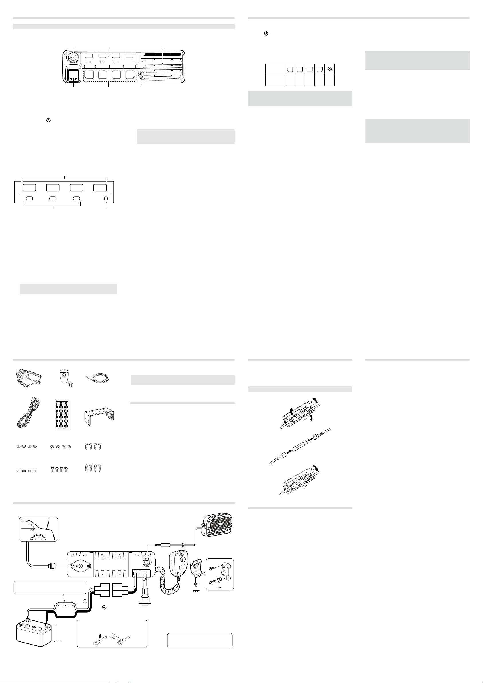
D Front panel
1
Function indicators
1 2 3 4
TX/RX
Speaker
P0 P1 P2 P3
34 2
AF VOLUME CONTROL KNOB [VOL]
1
Rotate the knob to adjust the audio output level.
L Minimum audio level is preset.
2POWER KEY [ ]
Push to turn the transceiver ON or OFF.
L The following optional functions are available at
power ON:
• Automatic scan start
• Password prompt
D Function indicators
1
1 2 3 4
TX/RX
3 2
CHANNEL INDICATOR
1
Indicates the operating channel.
•
Blinks when receiving a signal during a scan.
•
All indicators blink while entering the start up
•
password.
TX/RX INDICATOR
2
Lights red while transmitting.
•
Lights green while the channel is busy (receiving).
•
Blinks orange when the matching 2-tone or 5-tone
•
call is received.
Alternately blinks green and red when a
•
programming error has occurred.
ACTIVATED KEY INDICATORS (P0/P1/P2)
3
Lights when a assgined key function is activated.
When the supplied DC voltage is high, all
NOTE:
indicators blink. Check the DC voltage.
DEALER-PROGRAMMABLE KEYS
3
Required functions can be independently programmed
by your dealer.
MICROPHONE CONNECTOR
4
Connect the supplied or optional microphone.
CAUTION: DO NOT
microphones. The pin assignments may be dierent
and may damage the transceiver.
Microphone
D
The supplied or optional microphone has a PTT switch
and a hanger hook.
The following functions are available when the
L
microphone is ON or OFF hook, depending on the
presetting:
Automatic scan starts when you put it ON hook.
•
Scan is cancelled when you take it OFF hook.
•
Scan is paused when you take it OFF hook.
•
Automatically selects the Priority channel when you
•
take it OFF hook.
Sets to the Inaudible mode (mute state) when you
•
put it ON hook.
Sets to the Audible mode (unmute state) when you
•
take it OFF hook.
connect non-specied
D Turning ON the transceiver
1. Push [ ] to turn ON the transceiver.
2. If the transceiver is preset for a start up password, enter
the digit codes as directed by your dealer.
L The keys shown below can be used for password
entry.
The transceiver detects numbers in the same
block as identical.
are the same.
KEY
NUMBER
NOTE: If all channel indicators still blink after entering 4
digits, the entered code number may be incorrect. Turn
OFF the transceiver and re-enter your password.
Therefore “01234” and “56789”
P0 P1 P2 P3
0
5
2
1
7
6
4
3
9
8
D Selecting a channel
There are several methods to select channels, and they
may dier, depending on the presetting.
To select an operating channel:
• Push [CH Up] or [CH Down].
• Push one of [MR-CH 1] ~ [MR-CH 4].
AUTOMATIC SCAN TYPE:
Channel setting is not necessary for this type. When
turning ON the transceiver, it automatically starts
scanning, and stops when a signal is detected.
D Receiving and transmitting
Receiving:
1. Push [CH Up] or [CH Down] to select a channel.
2. When receiving a call, rotate [VOL] to adjust the audio
output level to a comfortable listening level.
NOTE: Depending on the presetting, the transceiver
automatically transmits the microphone audio for the
preset period of time, when a matching RX code signal is
received.
Transmitting:
1. Wait for the channel to become clear to avoid
interference.
L The channel is busy when the busy icon is displayed.
2. Take the microphone OFF from the hook.
• The Audible mode is selected.
• A priority channel may be automatically selected.
3. While holding down [PTT], speak at your normal voice
level.
4. Release [PTT] to receive.
IMPORTANT: To maximize the readability of your signal:
1. After pushing [PTT], pause briefly before you start
speaking.
2. Hold the microphone 5 to 10 cm (2 to 4 inches) from
your mouth, then speak at your normal voice level.
SUPPLIED ACCESSORIES
Microphone
DC power cable Function name
Flat washers
Spring washers
Microphone hanger
and screw set
stickers*
Nuts Mounting screws
Bracket bolts Self-tapping screws
REAR PANEL CONNECTION
1
Antenna
ANTENNA CONNECTOR
Connect to an antenna. Ask
your dealer about antenna
selection and placement.
2
EXTERNAL SPEAKER JACK
Connect to a 4 ~ 8 Ω external speaker.
q
Microphone
hanger cable
Mounting bracket
(5×12)
(5×20)
* Used for labelling the programmable function keys
according to their assinged functions.
NOTE: Some accessories are not supplied, or the shape
is dierent, depending on the transceiver version.
ANTENNA
A key element in the performance of any communication
systems is the antenna. Contact your dealer for
information regarding antennas and how to install them.
3
MICROPHONE HANGER
Connect the supplied microphone
hanger to the vehicle’s ground
for microphone ON/OFF hook
functions.
Optional speaker
e
w
FUSE REPLACEMENT
Fuses are installed in the supplied DC power cable. If a
fuse blows, track down the source of the problem, repair it,
and then replace the damaged fuse with a new rated one.
L Fuse rating: 20 A, 10 A*
* For the 25 W transceivers
NOTE: Use only specied fuses.
CLEANING
If the transceiver becomes dusty or dirty, wipe it clean with
a soft, dry cloth.
OPTIONS
• OPC-1132A, OPC-347 DC POWER CABLE
2 fuse holders are attached. USE only a 20 A fuse.
OPC-1132A: 3 m (9.8 ft)
OPC-347: 7 m (23 ft)
• OPC-1939, OPC-2078 ACC CABLE
Connects to an external terminal.
OPC-1939: D-sub 15-pin, an external level converter
OPC-2078: D-sub 25-pin, built-in level converter
• HM-152, HM-152T, HM-148G, HM-148T,
HAND MICROPHONE
HM-152: Hand microphone
HM-152T: DTMF microphone
HM-148G: Self ground heavy duty microphone
HM-148T: Self ground heavy duty DTMF microphone
• SM-26 DESKTOP MICROPHONE
• SP-30, SP-35, SP-35L EXTERNAL SPEAKER
Input impedance: 4 Ω
SP-30: Rated input: 20 W, Maximum input: 30 W
SP-35, SP-35L: Rated input: 5 W, Maximum input: 7 W
• UT-108R DTMF DECODER UNIT
Provides pager and code squelch capabilities.
• UT-109R/UT-110R VOICE SCRAMBLER UNIT
Non-rolling type (UT-109R) and Rolling type (UT-110R)
voice scrambler units provides higher communication
security.
(user supplied) is required.
R WARNING! NEVER remove the
fuse-holders from the DC power cable.
Red
12 V
Battery
t
Black
Use the terminals for the
NOTE:
cable connections.
Crimp
Solder
4
OPTIONAL CABLE
r
(OPC-1939, OPC-2078)
Connect an external modem
or dimmer control.
5
DC POWER RECEPTACLE
Connect to a 12 V DC battery. Pay
attention to polarities.
R WARNING! NEVER connect to
a 24 V battery. This could damage
the transceiver.
 Loading...