

Page 1

INSTRUCTION MANUAL
VHF TRANSCEIVERS
iF3262DT
iF3262DS
UHF TRANSCEIVERS
iF4262DT
iF4262DS
The photo shows the
UHF transceiver.
Page 2

IMPORTANT
EXPLICIT DEFINITIONS
READ ALL INSTRUCTIONS carefully and com-
pletely before using the transceiver.
SAVE THIS INSTRUCTION MANUAL — This
instruction manual contains important oper ating instructions
for the IC-F3262DT, IC-F3262DS VHF TRANSCEIVERS and
IC-F4262DT, IC-F4262DS UHF TRANSCEIVERS.
This instruction manual includes some functions which are
usable only when they are preset by your dealer. Ask your
dealer for details.
See the operating guide for details of IDAS™ NXDN™,
BIIS, MDC and LTR
for details.
®
system operations. Ask your dealer
WORD DEFINITION
RDANGER!
RWARNING!
CAUTION
NOTE
Icom, Icom Inc. and the Icom logo are registered trademarks of Icom Incorporated (Japan) in Japan, the United States, the United Kingdom, Germany,
France, Spain, Russia and/or other countries.
IDAS is trademark of Icom Incorporated (Japan).
NXDN is a trademark of Icom Incorporated and JVC KENWOOD Corporation.
LTR is a registered trademark of the E.F.Johnson Technologies, INC. in the
United States.
All other products or brands are registered trademarks or trademarks of their
respective holders.
Personal death, serious injury or an explosion may occur.
Personal injury, fire hazard or electric
shock may occur.
Equipment damage may occur.
If disregarded, inconvenience only. No risk
of personal injury, fire or electric shock.
i
Page 3

PRECAUTIONS
DANGER! NEVER short the terminals of the battery
R
pack.
DANGER! Use and charge only specified Icom battery
R
packs with Icom radios or Icom chargers. Only Icom battery
packs are tested and approved for use with Icom radios or
charged with Icom chargers. Using third-party or counterfeit
battery packs or chargers may cause smoke, fire, or cause
the battery to burst.
WARNING! NEVER hold the transceiver so that
R
the antenna is very close to, or touching exposed parts of
the body, especially the face or eyes, while transmitting. The
transceiver will perform best if the microphone is 5 to 10 cm
away from the lips and the transceiver is vertical.
WARNING! NEVER operate the transceiver with
R
a headset or other audio accessories at high volume levels.
Hearing experts advise against continuous high volume operation. If you experience a ringing in your ears, reduce the
volume level or discontinue use.
WARNING! NEVER operate the transceiver while
R
driving a vehicle. Safe driving requires your full attention—
anything less may result in an accident.
CAUTION: MAKE SURE the flexible antenna, bat-
tery pack and jack cover are securely attached to the transceiver, and that the antenna and battery pack are dry before
attachment. Exposing the inside of the transceiver to dust or
water will result in serious damage to the transceiver.
DO NOT operate the transceiver near unshielded electri-
cal blast ing caps or in an explosive atmosphere.
DO NOT push [PTT] when not actually intending to transmit.
DO NOT use or place the transceiver in direct sunlight or in
areas with temperatures below –25°C or above +55°C.
The basic operations, transmission and reception of the transceiver are guaranteed within the specified operating temperature range. However, the LCD display may not be operate
correctly, or show an indication in the case of long hours of
operation, or after being placed in extremely cold areas.
DO NOT modify the transceiver. The transceiver warranty does
not cover any problems caused by unauthorized modification.
DO NOT use harsh solvents such as benzine or alcohol
when cleaning, as they will damage the transceiver surfaces.
BE CAREFUL! The transceiver will become hot when
operating it continuously for long periods of time.
ii
Page 4

PRECAUTIONS (Continued)
VOICE CODING TECHNOLOGY
BE CAREFUL! The transceiver meets IP67 require-
ments for dust-tight and waterproof protection. However, once
the transceiver has been dropped, dust-tight and waterproof
protection cannot be guaranteed because of possible damage to the transceiver’s case or the waterproof seal.
Even when the transceiver power is OFF, a slight current still
flows in the circuits. Remove the battery pack or batteries from
the trans ceiver when not using it for a long time. Otherwise,
the installed battery pack or batteries will become exhausted,
and will need to be recharged or replaced.
MAKE SURE to turn OFF the transceiver power before
connect ing the supplied/optional equipment.
For IC-F4262
• The GPS receiver may not work if the transceiver transmits
near the 510 MHz. This is made in the internal circuit and
does not indicate a transceiver malfunction.
The AMBE+2™ voice coding Technology embodied in this
product is protected by intellectual property rights including
patent rights, copyrights and trade secrets of Digital Voice
Systems, Inc. This voice coding Technology is licensed solely
for use within this Communications Equipment. The user of
this Technology is explicitly prohibited from attempting to extract, remove, decompile, reverse engineer, or disassemble
the Object Code, or in any other way convert the Object Code
into a human-readable form. U.S. Patent Nos.
#5,870,405, #5,826,222, #5,754,974, #5,701,390, #5,715,365,
#5,649,050, #5,630,011, #5,581,656, #5,517,511, #5,491,772,
#5,247,579, #5,226,084 and #5,195,166.
iii
Page 5

TABLE OF CONTENTS
IMPORTANT .......................................................................... i
EXPLICIT DEFINITIONS ....................................................... i
PRECAUTIONS .................................................................... ii
VOICE CODING TECHNOLOGY ........................................ iii
TABLE OF CONTENTS ....................................................... iv
1 ACCESSORIES ...........................................................1–3
Supplied accessories ■ ................................................... 1
Accessory attachments ■ ................................................ 1
2 PANEL DESCRIPTION .............................................. 4–10
Front panel ■ ................................................................... 4
Function display ■ ...........................................................5
Programmable function keys ■ ........................................ 6
3 BASIC OPERATION ................................................11–18
Turning power ON ■ ......................................................11
Channel selection ■ ......................................................12
Call procedure ■ ............................................................13
Receiving and transmitting ■ ......................................... 13
User set mode ■ ............................................................16
Scrambler function ■ .....................................................16
Stun function ■ .............................................................. 16
Emergency transmission ■ ............................................ 17
Man Down Emergency Call ■ ........................................17
Automatic Key Lock function ■ ...................................... 18
Priority A channel selection ■ ........................................ 18
4 BATTERY CHARGING ............................................19–23
Caution ■ .......................................................................19
Optional battery chargers ■ ...........................................21
5 BATTERY CASE ......................................................24–26
BP-240 optional battery case ■ ..................................... 24
BP-261 optional battery case ■ ..................................... 25
6 SWIVEL BELT CLIP ................................................27–28
MB-93 contents ■ ..........................................................27
To attach ■ ....................................................................27
To detach ■ ...................................................................28
7 SPEAKER MICROPHONE ............................................29
Optional HM-184/HM-184H ■ .......................................29
To attach ■ ....................................................................29
8 OPTIONS .................................................................30–31
9 COUNTRY CODE LIST ................................................. 32
1
2
3
4
5
6
7
8
9
10
11
12
13
14
15
16
iv
Page 6
1
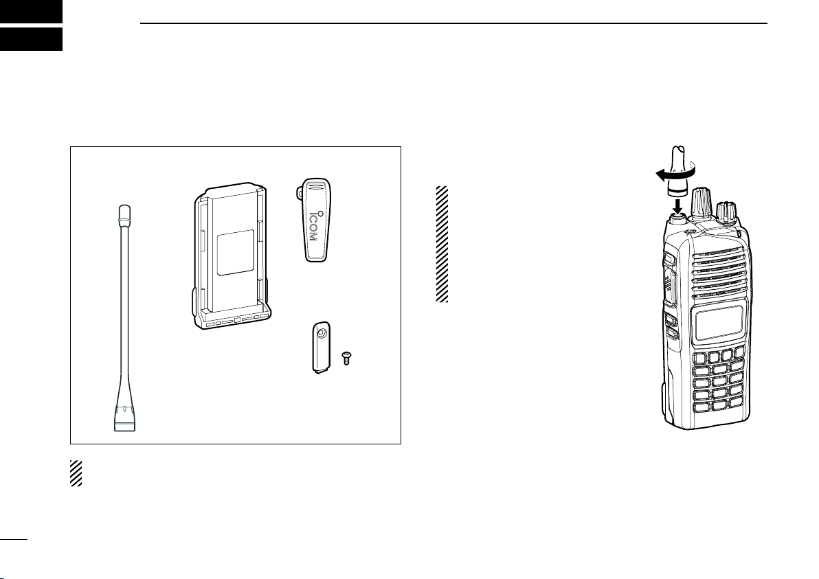
Battery pack Belt clip
Connector cover
(with screw)
Flexible antenna
(This illustration is
for the UHF type.)
ACCESSORIES
Supplied accessories ■
The following accessories are supplied.
NOTE: Some accessories are not supplied, depending on
the transceiver version.
Accessory attachments ■
Flexible antenna D
Connect the supplied flexible antenna
to the antenna connector.
CAUTION:
• NEVER carry the transceiver by
holding antenna.
• DO NOT connect any antenna
other than those listed on page
31.
• Transmitting without an antenna
will damage the transceiver.
1
Page 7
ACCESSORIES
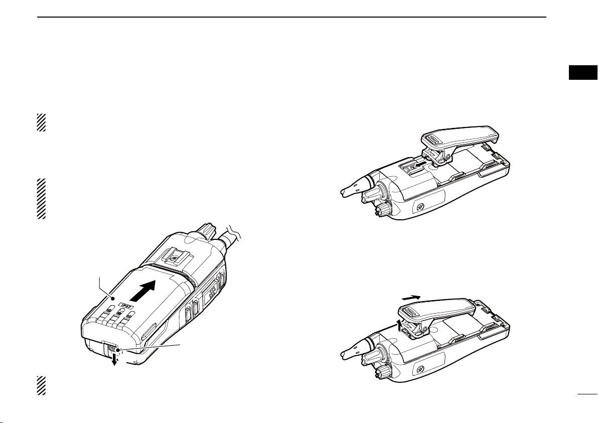
q
w
Battery release
button
w
q
1
Battery pack D
To attach the battery pack:
Slide the battery pack in the direction of the arrow (q) until the
battery release button makes a ‘click’ sound.
NOTE: Push on the bottom of the pack to make sure the
release button is firmly locked.
To remove the battery pack:
Push the battery release button in the direction of the arrow
(w), as shown below. The battery pack is then removed.
NEVER remove or attach the battery pack when the trans-
ceiver is wet or soiled. This may result water or dust getting into the transceiver/battery pack and may result in the
transceiver being damaged.
Belt clip D
To attach the belt clip:
q Remove the battery pack if it is attached.
w Slide the belt clip in the direction of the arrow until the belt
clip locks and makes a ‘click’ sound.
To detach the belt clip:
q Remove the battery pack if it is attached.
w Pinch the clip (q), and slide the belt clip in the direction of
the arrow (w).
1
2
3
4
5
6
7
8
9
10
11
12
13
14
15
16
NOTE: Keep the battery pack terminals clean. It’s a good
idea to occasionally clean them.
2
Page 8
ACCESSORIES
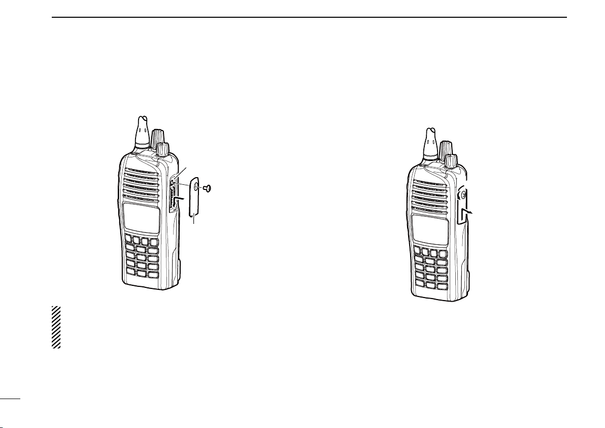
q
w
Multiconnector
Connector
cover
q
w
1
Connector cover D
To attach the connector cover:
q Place the connector cover over the multi-connector.
w Tighten the screw.
CAUTION:
Attach the connector cover when optional equipment is not
used. Otherwise the terminals of the multi-connector may
short out, and this could damage the transceiver.
To detach the connector cover:
q Remove the screw using a Phillips screwdriver.
w Detach the connector cover to connect optional equip-
ment.
3
Page 9
PANEL DESCRIPTION
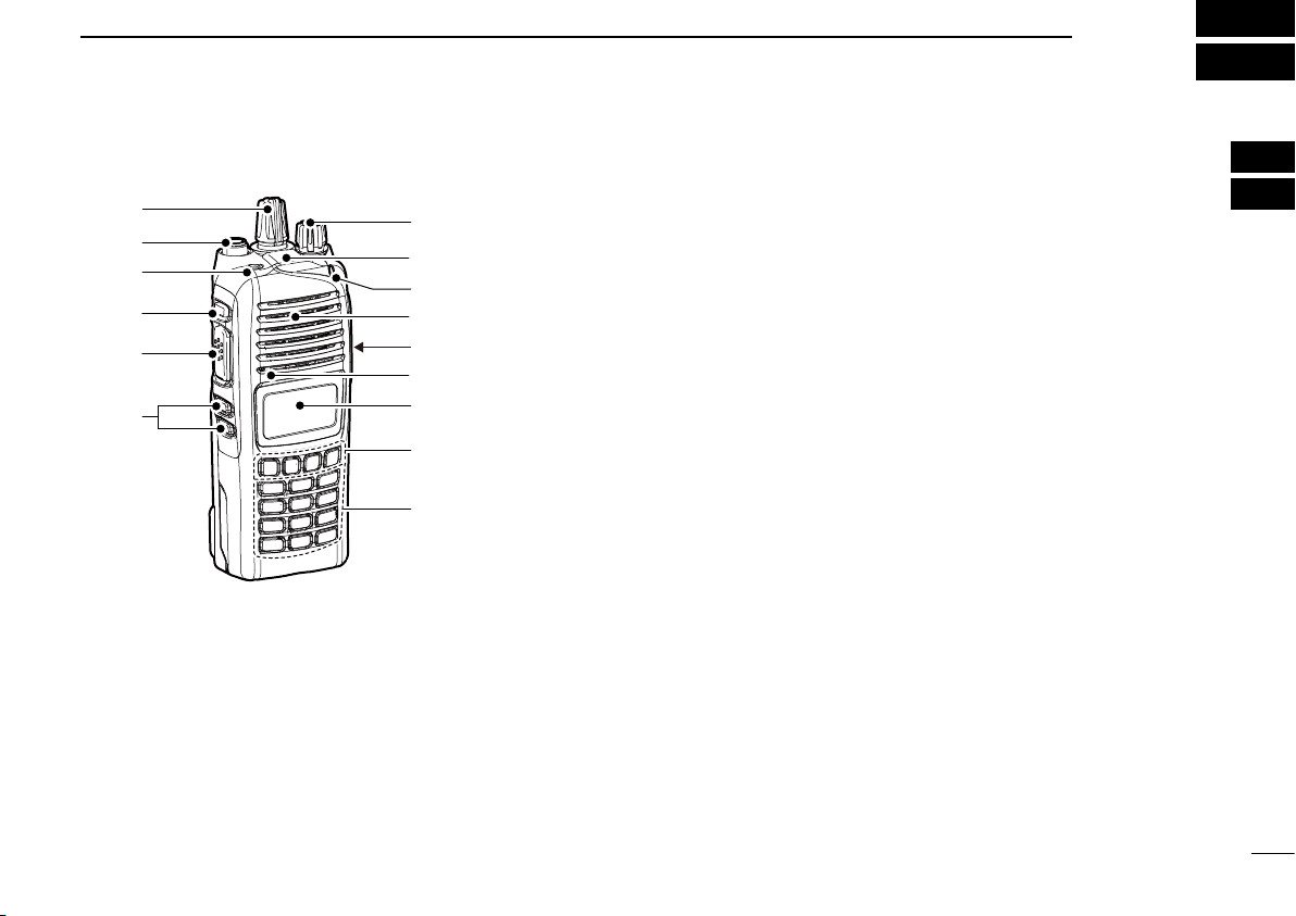
w
e
t
r
y
q
!1
!0
o
!2
u
i
Microphone
Speaker
GPS receiver*
*A GPS receiver is
bult-in, depending on
the transceiver version.
2
Front panel ■
q ROTARY SELECTOR
Rotate to select the memory channels or the operating
zone, depending on the presetting.
w ANTENNA CONNECTOR
Connect the supplied antenna. (p. 1)
e DEALER-PROGRAMMABLE KEY [EMR]
Desired functions can be preset by your dealer.
(p. 6)
r DEALER-PROGRAMMABLE KEY [Side1]
Desired functions can be preset by your dealer.
(p. 6)
t PTT SWITCH [PTT]
Hold down to transmit, release to receive.
y DEALER-PROGRAMMABLE KEYS [Side2]/[Side3]
Desired functions can be preset by your dealer. (p. 6)
u 10-KEYPAD (Depending on the version)
The keypad allows you to enter digits to:
• Select memory channels
• Select tone channels
• Select DTMF codes (during transmit)
• Set TX codes
• Start up with the password
i DEALER-PROGRAMMABLE KEYS [P0] to [P3]
Desired functions can be preset by your dealer. (p. 6)
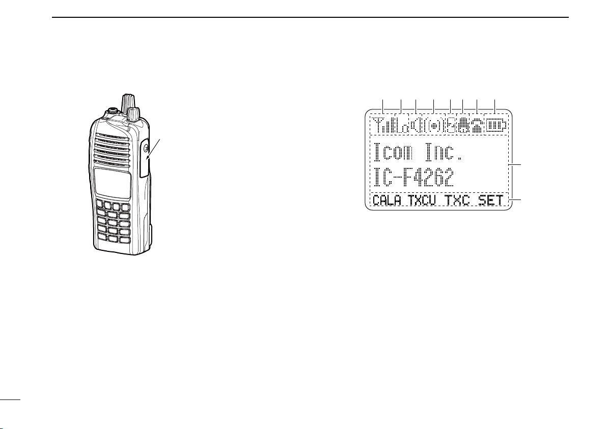
o FUNCTION DISPLAY (p. 5)
Displays a variety of information such as an operating
channel number/name, Set mode contents, DTMF code,
selected functions and so on.
1
2
3
4
5
6
7
8
9
10
11
12
13
14
15
16
4
Page 10
Connector cover
NOTE: Attach the connector cover when optional
equipment is not used.
See page 3 for details.
SET
CALA TXCU
TXC
q t iuyrew
o
!0
PANEL DESCRIPTION
2
!0 MULTI-CONNECTOR
Connects to optional equipment.
!1 BUSY/TRANSMIT INDICATOR
➥Lights green while receiving a signal, or when the
squelch is open.
➥Lights red while transmitting.
!2 VOLUME CONTROL [VOL]
Rotate to turn the transceiver power ON or OFF, and ad-
just the audio level.
5
Function display ■
q SIGNAL STRENGTH ICON
Indicates relative signal strength level.
w LOW POWER ICON
Appears when low output power is selected.
• When the battery power decreases to a specied level, low
power is automatically selected.
e AUDIBLE ICON
➥ Appears when the channel is in the ‘audible’ (unmute)
mode.
➥ Appears when a matched signal is received.
r COMPANDER ICON
Appears when the compander function is activated.
t SCRAMBLER ICON
Appears when the voice scrambler function is activated.
Page 11
PANEL DESCRIPTION
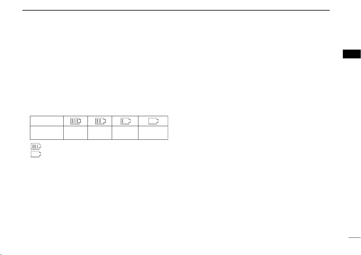
Indication
Full Mid
Charging
required
Exhausted
Battery
Battery level
blinks when the battery is exhausted.
blinks when the battery is over charged.
2
y BELL ICON
Appears or blinks when a matched signal is received, de-
pending on the presetting.
u CALL CODE MEMORY ICON
Appears when the call code memory is selected.
i BATTERY ICON
Appears or blinks when the battery power decreases to a
specified level.
o ALPHANUMERIC DISPLAY
➥ Displays the operating channel number, channel name,
Set mode contents, DTMF code, and so on.
➥ The display mode can be set to one line or two lines.
Ask your dealer for details.
• In this instruction manual, the LCD illustration is described
using the two-line display mode.
!0 KEY ICONS
Indicates the programmed function of the front panel keys
([P0], [P1], [P2] and [P3]).
Programmable function keys ■
The following functions can be assigned to the [EMR],
[Side1], [Side2], [Side3], [P0], [P1], [P2] and [P3] program-
mable function keys.
Consult your Icom dealer or system operator for details concerning your transceiver’s programming.
CH UP AND DOWN KEYS “UP” “DOWN”
➥ Push to select an operating channel. When [Rotary selec-
tor] selects “operating channel,” this key is disabled.
➥ Push to select a transmit code channel after pushing [TX
Code CH Select].
➥ Push to select a DTMF channel after pushing [DTMF Au-
todial].
➥ Push to select a scan group after holding down [Scan].
➥ Push to select the desired application type, individual/talk-
group ID, TX status message and SDM (Short Data Message) after pushing [Digital Button].
1
2
3
4
5
6
7
8
9
10
11
12
13
14
15
16
6
Page 12

PANEL DESCRIPTION
2
ZONE KEY “ZONE”
Push this key, then push [CH Up] or [CH Down] to select the
desired zone. When [Rotary selector] selects the “operating
zone,” this key operation is disabled.
What is a “zone”?— Selected channels are assigned to a
zone according to how they are to be used in a group. For
example, ‘Staff A’ and ‘Staff B’ are assigned to a “Business” zone, and ‘John’ and ‘Cindy’ are assigned to a “Private” zone.
ZONE UP AND DOWN KEYS “ZNUP” “ZNDN”
Push to select an operating zone. When [Rotary selector] selects an “operating zone,” these keys are disabled.
SCAN KEY “SCAN”
➥ Push to start or cancel a scan.
• When the Power ON Scan function is activated, push to pause
the scan. The paused scan resumes after the specified time period has passed.
➥ Hold down this key for 1 second to display the scan group,
then push [CH Up] or [CH Down] to select the desired
group.
SCAN ADD/DEL (TAG) KEY “SCAD”
➥ Push to add a channel to, or delete it from the current scan
group.
1. Push to display the scan group, then push [CH Up] or
[CH Down] to select the desired group.
2. Push to add a channel to, or delete it from the selected
group.
3. Hold down for 1 second to exit the scan group selection
mode.
➥ While a scan is paused on a non-priority channel, push
this key to delete the selected channel from the scan
group.
Depending on the presetting, the cleared channel may
be added to the scan group again after the scan is cancelled. (Nuisance Delete function)
PRIORITY CHANNEL KEYS “PRA” “PRB”
Push to select the Priority A or Priority B channel.
PRIORITY CHANNEL (REWRITE) KEYS “PRAR” “PRBR”
➥ Push to select the Priority A or Priority B channel.
➥ Hold down [Prio A (Rewrite)] or [Prio B (Rewrite)] for
1 second to rewrite the Priority A or Priority B channel as
the operating channel.
7
Page 13

PANEL DESCRIPTION
2
MEMORY CH 1/2/3/4 KEYS “CH1” “CH2” “CH3” “CH4”
Push to directly select memory channels 1 to 4.
MONI KEY “MON”
➥ Push to mute and release the CTCSS (DTCS) or 2/5-tone
squelch mute. Open any squelch or deactivate any mute
while holding down this key. (LMR operation only)
➥ Independently activates one or two of the following func-
tions on each channel. (PMR operation only)
• Hold down to unmute the channel (audio is heard; ‘Audible’
mode).
• Push to mute the channel (sets to ‘Inaudible’ only).
• Push after the communication is nished to send a ‘reset code’.
(5-tone/BIIS operation only)
NOTE: The unmute mode (‘Audible’ mode) may auto-
matically return to the mute mode (‘Inaudible‘ mode)
after a specified period.
LIGHT KEY “LIGT”
Push to temporarily turn ON the transceiver’s backlight, only
when the backlight function is turned OFF in the User set mode.
LOCK KEY “LOCK”
➥ Hold down for 1 second to electronically lock all program-
mable keys to prevent accidental frequency changes and
unnecessary function access, except the following:
[PTT], [Call] (incl. Call A and Call B), [Moni(Audi)],
[Light], [Emergency], [Surveillance], [Lone Worker] and
[OPT 1/2/3].
➥
Hold down for 1 second again to turn the lock function OFF.
LONE WORKER KEY “LONE”
Push to turn the Lone Worker function ON or OFF.
• If the Lone Worker function is activated, the Emergency function is
automatically turned ON after the specified time period has passed
with no operation performed.
HIGH/LOW KEY “H/L”
Push to select the transmit output power temporarily or permanently, depending on the presetting.
• Ask your dealer for the output power level for each selection.
TONE/RAN CH SELECT KEY “T SEL”
➥ While in the analog mode, push to enter the continuous
tone channel selection mode. Then select the desired tone
frequency/code setting using [CH Up] or [CH Down]. After
the selection, push this key again to set the tone/code.
➥ While in the digital mode, push to enter the RAN channel
selection mode. Then select the desired RAN setting using
[CH Up] or [CH Down]. After the selection, push this key
again to set the RAN.
➥ While in the mixed (digital and analog) mode, push to enter
the continuous tone channel selection mode. Then select
the desired tone frequency/code setting using [CH Up] or
[CH Down]. After the selection, push this key to set the
tone/code. After that, the RAN channel selection screen
appears. Select the desired RAN setting using [CH Up] or
[CH Down]. After the selection, push this key again to set
the RAN.
1
2
3
4
5
6
7
8
9
10
11
12
13
14
15
16
8
Page 14

PANEL DESCRIPTION
2
C.TONE CH ENT KEY “TSEL”
Push to enter the continuous tone channel selection mode.
Then push [CH Up] or [CH Down] to select the desired tone
frequency/code setting. The selected channel remains set as
a continuous tone channel until another channel is designated as such.
TALK AROUND KEY “TA”
Push to turn the talk around function ON or OFF.
• The talk around function equalizes the transmit frequency to the
receive frequency for transceiver-to-transceiver communication.
WIDE/NARROW “W/N”
Push to switch the IF bandwidth between wide and narrow.
• The wide passband width is preset to either 25.0 or 20.0 kHz by
your dealer (PMR operation only).
DTMF AUTODIAL KEY “DTMA”
Push to enter the DTMF channel selection mode. Then push
[CH Up] or [CH Down] to select the desired DTMF channel.
After selecting the DTMF channel, push again to transmit the
selected DTMF code.
RE-DIAL KEY “DTMR”
Push to transmit the last-transmitted DTMF code.
CALL KEYS “CALL” “CALA” “CALB”
Push to transmit a 2/5-tone or BIIS ID code.
• A Call transmission may be necessary before you call another sta-
tion, depending on your signaling system.
• [Call A] and/or [Call B] may be selectable when your system
employs selective ‘Individual/Group’ calls. Ask your dealer which
call is assigned to each key.
EMERGENCY KEY “EMR”
Hold down to transmit an emergency call.
• The emergency call transmits and beep sounds. The display does
not change.
• The transceiver can transmit the emergency call silently, or with the
display changing, depending on the presetting. Ask your dealer for
details.
• If you want to cancel the emergency call, hold down the key again
before transmitting it.
• The emergency call is transmitted only one time, or repeatedly until
receiving a control code, depending on the presetting.
SURVEILLANCE KEY “SURV”
Push to turn the surveillance function ON or OFF.
When this function is turned ON, a beep is not heard and the
LCD backlight and BUSY indicator do not light when a signal
is received or a key is pushed.
TX CODE ENTER KEYS “TXCE”
Push to directly enter the ID code edit mode, for both 5-tone
and MSK. Then push [CH Up] or [CH Down] to set the desired
digit. (p. 15)
9
Page 15

PANEL DESCRIPTION
2
TX CODE CHANNEL SELECT KEY “TXC”
Push to enter the TX code channel selection mode. Then
push [CH Up] or [CH Down] to set the desired channel. (pp.
14, 15)
TX CODE CHANNEL UP/DOWN KEYS “TXCU” “TXCD”
Push to select a TX code channel directly.
ID-MEMORY SELECT KEY “IDMS”
➥ Recalls detected ID codes.
• Push this key, then push [CH Up] or [CH Down] to select the ID
code.
• Up to ve IDs can be memorized.
➥ Hold down for 1 second to erase the selected ID’s.
SCRAMBLER/ENCRYPTION KEY “SCR”
➥ While in the analog mode operation, push to toggle the
voice scrambler function ON or OFF.
➥ While in the digital mode operation, push to toggle the
encryption transmission function ON or OFF.
COMPANDER KEY “COMP”
Push to toggle the compander function ON or OFF.
The compander function reduces noise components from the
transmitting audio to provide clear communication.
USER SET MODE KEY “SET”
➥ Hold down for 1 second to enter the User set mode.
• While in the User set mode, push this key to select an item, and
change the value or condition using [CH Up] or [CH Down].
➥ Hold down this key for 1 second again to exit the User set
mode.
OPT OUT KEYS “OP1” “OP2” “OP3”
Push to control the output signal level from the optional unit
connector.
OPT MOMENTARY KEYS “O1M” “O2M” “O3M”
Push to control the output signal level from the optional unit
connector.
1
2
3
4
5
6
7
8
9
10
11
12
13
14
15
16
10
Page 16

KEY
NUMBER
0
5
4
9
3
8
2
7
1
6
(Side1)
P0 P1 P2 P3
3
BASIC OPERATION
Turning power ON ■
Prior to using the transceiver for the first time, the battery
pack must be fully charged for optimum life and operation.
(p. 21)
q Rotate [VOL] to turn ON the power.
w If the transceiver is programmed for a start up password,
input the digit codes as directed by your dealer.
• The 10-keypad can be used for password input, depending on
the transceiver version.
• The keys in the table below can be used for password input.
• The transceiver detects numbers in the same block as identical.
Therefore “01234” and “56789” are the same.
e If the “PASSWORD” indication does not clear after input-
ting 6 digits, the input code number may be incorrect. Turn
OFF the power and start over.
Battery type selection D
When turning ON the transceiver, the battery type must be
selected according to the attached battery type.
Turn OFF the power. q
While holding down [EMR] and [PTT], turn ON the power w
with rotating [VOL] to toggle the attaching battery type.
• After the display appears, release [EMR] and [PTT].
• “ DRY BATT” is displayed for about 3 seconds, then the low power
icon “Lo” appears when the battery case is selected. The transmit output power is automatically set to low1.
• “LI-ION” is displayed for about 3 seconds when the Lithium-ion
battery pack is selected.
• This operation may not be available, depending on the presetting.
Ask your dealer for details.
11
Page 17

BASIC OPERATION
3
Channel selection ■
Several types of channel selections are available. Methods
may differ, depending on the presetting.
NON-ZONE TYPE:
To select the desired operating channel:
• Push [CH Up] or [CH Down].
• Rotate [ROTARY SELECTOR]*.
- Up to 16 preprogrammed channels can be selected.
• Push one of [MR-CH 1] to [MR-CH 4].
ZONE TYPE:
To select the desired zone:
• Push [Zone], then push [CH Up] or [CH Down].
• Push [Zone Up] or [Zone Down].
• Rotate [ROTARY SELECTOR]*.
- Up to 16 preprogrammed zones can be selected.
* Depending on the presetting.
When [ROTARY SELECTOR] selects “Operating channel,” [CH Up]/
[CH Down] are disabled.
When [ROTARY SELECTOR] selects “Operating zone,” [Zone] or
[Zone Up]/[Zone Down] are disabled.
AUTOMATIC SCAN TYPE:
Channel setting is not necessary for this type. When you turn
ON power, the transceiver automatically starts scanning.
Scanning stops when a call is received.
Voting operation D (for zone selection)
The transceiver automatically starts scanning when a zone,
specified for the voting operation, is selected.
The voting scan detects the signal of the repeater and automatically selects the strongest station.
1
2
3
4
5
6
7
8
9
10
11
12
13
14
15
16
12
Page 18

Selective calling
Non-selective calling
BASIC OPERATION
3
13
Call procedure ■
When your system employs tone signaling, excluding CTCSS
and DTCS, this call procedure may be necessary prior to
voice transmission. The tone signaling employed may be a
selective calling system which allows you to call only specific
station(s) and prevents unwanted stations from contacting
you.
q Select the desired TX code channel or 2/5-tone code ac-
cording to your System operator’s instructions.
• This may not be necessary, depending on the presetting.
• Refer to pages 14 or 15 for selection.
w Push [Call], assigned to one of the dealer programmable
keys.
e After transmitting, the remainder of your communication
can be carried out in the normal way.
Receiving and transmitting ■
CAUTION: Transmitting without an antenna will damage
the transceiver.
Receiving:
q Rotate [VOL] to turn ON the power.
w Push [CH Up] or [CH Down], or rotate [ROTARY SELEC-
TOR], depending on the presetting, to sequentially select
the conventional system channel.
e When receiving a call, adjust the audio output level to a
comfortable listening level.
NOTE: When a matched RX code signal is received, audio
from the microphone may be automatically transmitted for
a specied time period.*
* Depending on the presetting. Ask your dealer for details.
Transmitting:
Wait for the channel to become clear to avoid interference.
q While holding down [PTT], speak into the microphone at a
normal voice level.
• When a tone signaling system is used, the call procedure de-
scribed on the previous page may be necessary.
w Release [PTT] to receive.
IMPORTANT: To maximize the audio quality of your sig-
nal:
1. Pause briefly after pushing [PTT].
2. Hold the microphone 5 to 10 cm from your mouth, then
speak at a normal voice level.
Page 19

BASIC OPERATION
3
1
Transmitting notes D
•Transmitinhibitfunction
The transceiver has several inhibit functions which restrict
transmission under the following conditions:
- The channel is muted (‘Inaudible’ mode;
does not appear.)
- The channel is busy.
- Unmatched or matched CTCSS is received, depending on
the presetting.
- The selected channel is a ‘receive only’ channel.
•Time-outtimer
After continuous transmission for a preset time period, the
time-out timer causes the transceiver to stop transmitting.
•Penaltytimer
Once transmission is cut OFF, it is further inhibited for a
period determined by the Penalty timer.
“
” (Audible icon)
TX code channel selection D
If the transceiver has [TX Code CH Select] assigned to it,
the display can be toggled between the operating channel
number or name, and the TX code channel number or name.
When the TX code channel number, or name is displayed,
pushing [CH Up] or [CH Down] selects the TX code channel.
USING [TX CODE CH SELECT] KEY:
q Push [TX Code CH Select]— a TX code channel number
or name appears.
w Push [CH Up] or [CH Down] to select the desired TX code
channel.
e After selecting, push [TX Code CH Select] to set the
code.
• Return to the standby mode.
r Push [Call] to transmit the selected TX code.
USING [TX CODE CH UP]/[TX CODE CH DOWN] KEY:
If the transceiver has a [TX Code CH Up] or [TX Code CH
Down] key assigned, the preset TX code channel can be directly selected when pushed.
☞ Continued on the next page
2
3
4
5
6
7
8
9
10
11
12
13
14
15
16
14
Page 20

BASIC OPERATION
3
TX code number edit D
If the transceiver has [TX Code CH Select] or [TX Code
Enter] assigned, the TX code contents can be edited within
the allowable digits.
USING [TX CODE CH SELECT] KEY:
q Push [TX Code CH Select] to enter the TX code channel
selection mode.
• Select the desired operating channel before entering the TX
code channel selection mode, if necessary.
w Push [TX Code CH Select] for 1 second to enter the TX
code edit mode.
• The digit to be edited blinks.
e Push [TX Code CH Select] to select the desired digit to be
edited.
r Push [CH Up] or [CH Down] to select the desired digit.
t Push [TX Code CH Select] to set it. The digit to the right
will automatically blink.
y Repeat r and t to edit all allowable digits.
u After editing, push [TX Code CH Select] to set the code.
• Return to the standby mode.
i Push [Call] to transmit.
(PMR operation only)
USING [TX CODE ENTER] KEY:
q After pushing [TX Code CH Select], push [CH Up] or [CH
Down], or push [TX Code CH Up] or [TX Code CH Down]
to select the desired TX code channel.
w Push [TX Code Enter] to enter the TX code edit mode.
• The digit to be edited blinks.
e Push [TX Code Enter] to select the desired digit to be ed-
ited.
r Push [CH Up] or [CH Down] to select the desired digit.
t Push [TX Code Enter] to set. The digit to the right will au-
tomatically blink.
y Repeat r and t to edit all allowable digits.
u After editing, push [TX Code Enter] to set.
• Return to the standby mode.
i Push [Call] to transmit.
DTMF transmission D
If the transceiver has [DTMF Autodial] assigned, the automatic DTMF transmission function can be used. Up to 8
DTMF channels are selectable.
q Push [DTMF Autodial]— a DTMF channel appears.
w Push [CH Up] or [CH Down] to select the desired DTMF
channel.
e Push [DTMF Autodial] to transmit the DTMF code on the
selected DTMF channel.
15
Page 21

BASIC OPERATION
3
User set mode ■
The User set mode allows you to set seldom-changed settings and “customize” the transceiver operation to suit your
preferences and operating style.
Entering the User set mode:
q Hold down [SET] for 1 second to enter the User set
mode.
w Push [SET] several times to select the appropriate item.
Then push [CH Up] or [CH Down] to set the desired level
or option.
• In the User set mode, the selectable items are preset by your
dealer. The presetable items are Backlight, LCD contrast,
Beep, Beep Level, Ringer Level, SQL Level, AF Min Level,
Mic Gain, VOX Gain*, VOX Delay*, Battery Voltage, Signal
Moni, Lone Worker and System Info.
* Appears only when the external VOX unit is connected.
e Hold down [SET] for 1 second again to exit the User set
mode.
Scrambler function ■
The voice scrambler function provides private communication between stations. All transceiver versions have a built-in
frequency inversion type scrambler.
➥ Push [Scrambler] to toggle the scrambler function ON or
OFF.
• “ ” (Scrambler icon) appears when the function is ON.
Stun function ■
When the specified ID, set as a stun ID or kill ID, is received,
the stun function is activated.
When a stun ID is received, the transceiver becomes unusable. Entering the password (p. 11) or receiving a revive ID, is
necessary to operate the transceiver again.
When a kill ID is received, the transceiver switches to the
cloning required condition. Cloning the transceiver is necessary to operate the transceiver again.
1
2
3
4
5
6
7
8
9
10
11
12
13
14
15
16
16
Page 22

BASIC OPERATION
3
Emergency transmission ■
When [Emergency] is pushed for the specified time period, an
emergency signal is transmitted once, or repeatedly, on the
specified emergency channel, depending on the presetting.
A repeat emergency signal is automatically transmitted until
the transceiver receives an acknowledgement signal, or you
turn OFF the transceiver power.
When no emergency channel is specified, the signal is transmitted on the previously selected channel.
If you want to cancel the emergency call, hold down [Emergency] again before transmitting it.
If your transceiver is preset for Silent operation, you can
transmit an Emergency call without the beep sounding and
the LED indicator lighting.
IMPORTANT: It is recommended to set a separate emergency channel to provide reliable emergency calls.
NOTES D
Depending on the presetting, the following functions may be
automatically activated. Ask your dealer for details.
•AutoTXfunction
After the emergency call transmission, audio from the microphone is automatically transmitted for a specified time period.
•AutoRXfunction
After the emergency call transmission, the transceiver stands
by in the audible mode for the specified time period.
Man Down Emergency Call ■
This function is available, depending on the transceiver version.
When the transceiver has been left in a horizontal position for
the specied time period*, the transceiver enters the emergency mode, and then the countdown starts.
After the specied time period* has passed, an emergency
call is automatically transmitted once, or repeatedly.
If the transceiver is placed in a vertical position before the first
transmission, the transceiver exits the emergency mode and
the emergency call is cancelled.
IMPORTANT: It is recommended to set a separate emergency channel to provide reliable emergency calls.
17
Page 23

BASIC OPERATION
3
Automatic Key Lock function ■
When [Lock] is assigned to any key, and the Automatic Key
Lock timer is preprogrammed*, the key lock function can be
automatically turned ON after the specified time period has
passed with no key operation.
While the lock function is ON, hold down [Lock] for 1 second
to turn the function OFF.
*When “0” is programmed, this function is disabled.
Priority A channel selection ■
When one of the following operations is performed, the transceiver automatically selects the Priority A channel.
• Turning the power ON
The Priority A channel is selected each time the trans-
ceiver power is turned ON.
• Status call
The Priority A channel is selected when transmitting a
status call. (BIIS operation only)
• Clear down
The Priority A channel is selected after the clear down
signal is transmitted.
1
2
3
4
5
6
7
8
9
10
11
12
13
14
15
16
18
Page 24

4
BATTERY CHARGING
Caution ■
Misuse of Lithium-ion batteries may result in the following
hazards: smoke, fire, or the battery may rupture. Misuse
can also cause damage to the battery or degradation of
battery performance.
• R DANGER! Use and charge only specified Icom battery
packs with Icom radios or Icom charger. Only Icom battery
packs are tested and approved for use and charge with
Icom radios or Icom charger. Using third-party or counterfeit
battery packs or charger may cause smoke, fire, or cause
the battery to burst.
Battery caution D
• R DANGER! DO NOT hammer or otherwise impact the bat-
tery. Do not use the battery if it has been severely impacted
or dropped, or if the battery has been subjected to heavy
pressure. Battery damage may not be visible on the outside
of the case. Even if the surface of the battery does not show
cracks or any other damage, the cells inside the battery may
rupture or catch fire.
• R DANGER! NEVER use or leave battery packs in areas
with temperatures above +60˚C. High temperature buildup
in the battery, such as could occur near fires or stoves, inside a sun heated car, or in direct sunlight may cause the
battery to rupture or catch fire. Excessive temperatures may
also degrade battery performance or shorten battery life.
• R DANGER! DO NOT expose the battery to rain, snow,
seawater, or any other liquids. Never charge or use a wet
battery. If the battery gets wet, be sure to wipe it dry before
using. The battery is not waterproof.
• R DANGER! NEVER incinerate used battery packs since
internal battery gas may cause them to rupture, or may
cause an explosion.
• R DANGER! NEVER solder the battery terminals or
NEVER modify the battery pack. This may cause heat generation, and the battery may rupture, emit smoke or catch
fire.
• R DANGER! Use the battery only with the transceiver for
which it is specified. Never use a battery with any other
equipment, or for any purpose that is not specified in this
instruction manual.
• R DANGER! If fluid from inside the battery gets in your
eyes, blindness can result. Rinse your eyes with clean water,
without rubbing them, and see a doctor immediately.
19
Page 25

BATTERY CHARGING
4
• R WARNING! Immediately stop using the battery if it emits
an abnormal odor, heats up, or is discolored or deformed. If
any of these conditions occur, contact your Icom dealer or
distributor.
• R WARNING! Immediately wash, using clean water, any
part of the body that comes into contact with fluid from inside the battery.
• R WARNING! NEVER put the battery in a microwave oven,
high-pressure container, or in an induction heating cooker.
This could cause a fire, overheating, or cause the battery
to rupture.
• CAUTION: Always use the battery within the specified tem-
perature range for the transceiver (–25˚C to +55˚C) and the
battery itself (–20˚C to +60˚C). Using the battery out of its
specified temperature range will reduce the battery’s performance and battery life. Please note that the specified temperature range of the battery may exceed that of the transceiver.
In such cases, the transceiver may not work properly because it is out of its operating temperature range.
• CAUTION: Shorter battery life could occur if the battery is
left fully charged, completely discharged, or in an excessive
temperature environment (above +50˚C) for an extended
period of time. If the battery must be left unused for a long
time, it must be detached from the radio after discharging.
You may use the battery until the remaining capacity is
about half, then keep it safely in a cool dry place with the
temperature range as below:
–20˚C to +50˚C (within a month)
–20˚C to +35˚C (within three months)
Charging caution D
• R DANGER! NEVER charge the battery pack in areas with
extremely high temperatures, such as near fires or stoves,
inside a sun heated car, or in direct sunlight. In such environments, the safety/protection circuit in the battery will
activate, causing the battery to stop charging.
• R WARNING! NEVER charge or leave the battery in the
battery charger beyond the specified time for charging. If
the battery is not completely charged by the specified time,
stop charging and remove the battery from the battery charger. Continuing to charge the battery beyond the specified
time limit may cause a fire, overheating, or the battery may
rupture.
• R WARNING! NEVER insert the transceiver (battery at-
tached to the transceiver) into the charger if it is wet or
soiled. This could corrode the battery charger terminals or
damage the charger. The charger is not waterproof.
• CAUTION: NEVER charge the battery outside of the speci-
fied temperature range: BC-160 and BC-171 (0˚C to +45˚C),
BC-119 and BC-121 (+10˚C to +40˚C). Icom recommends
charging the battery at +20˚C. The battery may heat up or
rupture if charged out of the specified temperature range.
Additionally, battery performance or battery life may be reduced.
1
2
3
4
5
6
7
8
9
10
11
12
13
14
15
16
20
Page 26

BATTERY CHARGING
AC adapter
(A different type, or no AC adapter is
supplied, depending on the version.)
Transceiver
Battery
pack
Optional OPC-515L* (for
13.8 V power source) or
CP-23L (for 12 V cigarette
lighter socket) can be used
instead of the AC adapter.
CAUTION: NEVER
connect the OPC515L to a power
source using reverse
polarity. This will ruin
the battery charger.
White line:
Black line
:
*
Tu rn OFF
the power
4
Optional battery chargers ■
Rapid charging with the BC-160 D
The optional BC-160 provides rapid charging of the Li-ion
battery pack.
Charging time: Approximately 3.5 hours with the BP-232WP
The following items are additionally required:
• An AC adapter (may be supplied with BC-160, depending
on version) or the OPC-515L/CP-23L DC power cable.
21
Regular charging with the BC-171 D
The optional BC-171 provides regular charging of the Li-ion
battery pack.
Charging time: Approximately 11 hours with the BP-232WP
The following items are additionally required:
• An AC adapter (may be supplied with BC-171, depending
on version) or the OPC-515L/CP-23L DC power cable.
Page 27

BATTERY CHARGING
Screws supplied
with the charger
adapter
AD-106
Plugs
Sockets
This illustration shows
the BC-119N.
AC adapter
(A different type, or no AC
adapter is supplied, depending on the version.)
Optional OPC-515L* (for
13.8 V power source) or
CP-23L (for 12 V cigarette
lighter socket) can be used
instead of the AC adapter.
CAUTION: NEVER connect the OPC515L to a power source using reverse
polarity. This will ruin the battery charger.
White line: Black line
:
*
Transceiver
Battery
pack
AD-106 charger
adapter is installed
in the BC-119N.
Tu rn OFF
the power
4
AD-106 installation D
The AD-106 c h a r g e r a d a p t e r must be installed into the BC119N or BC-121N before battery charging.
q Connect the AD-106
BC-121N.
w Install the AD-106 into the holder space of the BC-119N/
BC-121N with the supplied screws.
c h a r g e r a d a p t e r and the BC-119N/
Rapid charging with the BC-119N+AD-106 D
The optional BC-119N provides rapidly charges the Li-ion
battery pack.
Charging time: Approximately 3.5 hours with the BP-232WP
The following items are additionally required.
• AD-106
• An AC adapter (may be supplied with BC-119N, depending
on version) or the OPC-515L/CP-23L DC power cable.
c h a r g e r a d a p t e r (purchase separately)
1
2
3
4
5
6
7
8
9
10
11
12
13
14
15
16
22
Page 28

BATTERY CHARGING
Transceiver
Battery
pack
AD-106 charger
adapters are installed
in each slot.
Tu rn OFF the power
OPC-656* DC power cable
(Connect with a DC power supply;
13.8 V/at least 7 A)
*Polarity of the OPC-656
Red line : Black line :
AC adapter
Guide rail
Tabs
4
Rapid charging with the BC-121N+AD-106 D
The optional BC-121N allows up to 6 battery packs to be simultaneously charged.
Charging time: Approximately 3.5 hours with the BP-232WP
The following items are additionally required.
(purchase separately)
• Six AD-106
• An AC adapter or the OPC-656 DC power cable
c h a r g e r a d a p t e r s
IMPORTANT: Battery charging caution
Ensure the guide tabs on the battery pack are correctly
aligned with the guide rails inside the charger adapter. This
illustration is for the BC-160.
23
CAUTION:
When using the OPC-656 DC power cable
NEVER reverse the polarity when connecting the OPC-
656 to a power source. This will ruin the battery charger.
OPC-656: Red line: +, Black line: _
Page 29

BATTERY CASE
q
BP-240
w
Fig.1
Fig.2
Fig.3
e
r
t
5
BP-240 optional battery case ■
When using the BP-240 battery case, install six AAA (LR03)
size alkaline batteries, as illustrated to the right. The BP-240
is constructed to the IPX4 waterproof standard.
q Unhook the battery cover release hook (q), and open the
cover in the direction of the arrow (w). (Fig.1)
w Install six AAA (LR03) size alkaline batteries. (Fig.2)
• Install only alkaline batteries.
• Be sure to observe the correct polarity.
e Replace the cover in the direction of the arrow (e), then
close (r). Push the battery cover release hook until it
makes a ‘click’ sound (t). (Fig.3)
CAUTION:
• When installing the batteries, make sure they are all the
same brand, type and capacity. Also, do not mix new and
old batteries together.
• Keep battery terminals clean. It’s a good idea to occasionally clean them.
• Never incinerate used battery cells since internal battery
gas may cause them to rupture.
•
Never expose a detached battery case to water. If the battery case gets wet, be sure to wipe it dry before using it.
NOTE: When the optional battery case is attached, the
battery type must be set to “DRY BATT” when turning ON
the transceiver. (p. 11)
1
2
3
4
5
6
7
8
9
10
11
12
13
14
15
16
24
Page 30

BP-261
Fig.1
Fig.2
Fig.3
t
r
e
q
w
BATTERY CASE
5
BP-261 optional battery case ■
Alkaline batteries installation D
Install six AA (LR6) size alkaline batteries as described below.
The BP-261 is constructed to the IPX4 waterproof standard.
Unhook the battery cover release hook ( q q), and open the
cover in the direction of the arrow (w). (Fig.1)
Install six AA (LR6) size alkaline batteries. (Fig.2) w
• Install only alkaline batteries.
• Be sure to observe the correct polarity.
Replace the cover in the direction of the arrow ( e e), then
close (r). Push the battery cover release hook until it
makes a ‘click’ sound (t). (Fig.3)
25
CAUTION:
• When installing the batteries, make sure they are all the
same brand, type and capacity. Also, do not mix new and
old batteries together.
• Keep battery terminals clean. It’s a good idea to occasionally clean them.
• Never incinerate used battery cells since internal battery
gas may cause them to rupture.
•
Never expose a detached battery case to water. If the battery case gets wet, be sure to wipe it dry before using it.
NOTE: When the optional battery case is attached, the
battery type must be set to “DRY BATT” when turning ON
the transceiver. (p. 11)
Page 31

BATTERY CASE
q
w
5
Battery case attachment D
Slide the battery pack in the direction of the arrow until the
battery release button makes a ‘click’ sound.
To remove the battery case:
Slide the battery case’s battery release button in the
direction of the arrow (q), and then push the release
button in the direction of the arrow (w). The battery
pack is then released.
NEVER remove or attach the battery case when the
transceiver is wet or soiled. This may result water or
dust getting into the transceiver or battery case and
may result in the transceiver being damaged.
1
2
3
4
5
6
7
8
9
10
11
12
13
14
15
16
26
Page 32
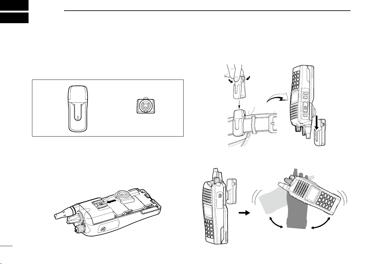
6
q w
Once the transceiver is locked in place,
it will swivel 360 degrees.
SWIVEL BELT CLIP
MB-93 contents ■
Qty.
q Belt clip ............................................................................1
w Base clip ..........................................................................1
To attach ■
q Remove the battery pack if it is attached. (p. 2)
w Slide the base clip in the direction of the arrow until it locks
and makes a ‘click’ sound.
r Clip the belt clip to a place on your belt. Insert the trans-
ceiver into the belt clip until the base clip is fully inserted
into the groove.
t Once the transceiver is locked in place, it swivels, as illus-
trated below.
27
e Attach the battery pack. (p. 2)
Page 33
SWIVEL BELT CLIP
w
q
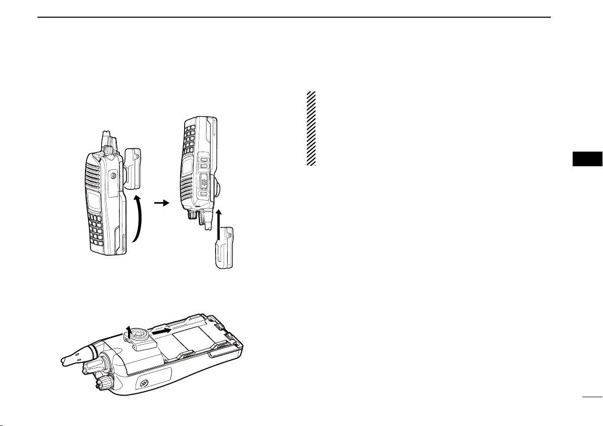
6
To detach ■
q Turn the transceiver upside down in the direction of the
arrow and pull it out of the belt clip.
w Remove the battery pack if it is attached. (p. 2)
e Pinch the clip (q), and slide the base clip in the direction
of the arrow (w).
CAUTION:
HOLD THE TRANSCEIVER TIGHTLY WHEN HANGING
OR DETACHING THE TRANSCEIVER FROM THE BELT
CLIP.
Otherwise the transceiver may not properly attach to the
holder or swivel, if the transceiver has been accidentally
dropped and the base clip is scratched or damaged.
1
2
3
4
5
6
7
8
9
10
11
12
13
14
15
16
28
Page 34

Tu rn OFF the transceiver power when attaching or detaching
the microphone.
Speaker
Belt clip
Microphone
PTT SWITCH
Hold down to
transmit;
release to receive.
CAUTION: Firmly attach
to the multi connector, but
do not overtighten.
A loose connection will allow water intrusion into
the connector; an overtightened connection will
damage the connector
pins in the transceiver.
Coin
Screw
7
SPEAKER MICROPHONE
29
NEVER immerse the connector in water. If the connector
becomes wet, be sure to dry it BEFORE attaching it to the
transceiver.
NOTE: The microphone element is located at the top of
the speaker microphone, as shown in the diagram above.
To maximize the readability of your transmitted signal
(voice), hold the microphone Approximately 5 to 10 cm
from your mouth, and speak at a normal voice level.
Optional HM-184/HM-184H ■
To attach ■
Attach the connector of the speaker microphone into the multi
connector on the transceiver and tighten the screw.
IMPORTANT: KEEP the connector cover attached to the
transceiver when the speaker microphone is not in use.
(p. 3)
Water will not get into the transceiver, even if the cover is
not attached. However, the terminals (pins) will become
rusty, or the transceiver will function abnormally if the connector becomes wet.
Page 35

OPTIONS
8
BATTERY PACKS D
•BP-232WPl i -i o n b at t e r y p a c k
Voltage: 7.4 V, Capacity: 2250 mAh (min.) 2300 mAh (typ.)
• Battery life
VHF UHF
GPS unit
Built in type 11 hrs. 11.5 hrs. 10.5 hrs. 11 hrs.
non GPS type 13 hrs. 13.5 hrs. 12 hrs. 12.5 hrs.
When the power save function is turned ON, and the operating
periods are calculated under the following conditions;
TX : RX : standby = 5 : 5 : 90
•BP-240/BP-261b a t t e r y c a s e
Battery case for AAA (LR03) × 6 alkaline
Battery case for AA (LR6) × 6 alkaline
BP-240 and BP-261 have IPX4 waterproof protection. When
in use, the transceiver’s waterproof rating meets IPX4.
Digital
mode
Analog
mode
Digital
mode
Analog
mode
DC CABLES D
•CP-23Lc i g a r e t t e l i g h t e r c a b l e
Allows charging of the battery pack through a 12 V cigarette
lighter socket. For use with the BC-119N/BC-160/BC-171
•OPC-515L/OPC-656
Allows charging of the battery pack using a 13.8 V power
source instead of the AC adapter.
OPC-515L : For BC-119N
OPC-656 : For BC-121N
d c p o w e r c a b l e s
CHARGERS D
•BC-119Nd e s k t o p c h a r g e r + AD-106 c h a r g e r a d a p t e r
+ BC-145S a c ad a p t e r
For rapid charging of battery packs. An AC adapter may be
supplied with the charger, depending on the version.
Charging time: Approximately 3.5 hours.
•
BC-121N m u l t i -c h a r g e r + AD-106 c h a r g e r a d a p t e r (6 pcs.)
+ BC-157S a c ad a p t e r
For rapid charging of up to 6 battery packs simultaneously.
Six AD-106s are required. An AC adapter should be purchased separately.
Charging time: Approximately 3.5 hours.
•BC-160
For rapid charging of battery packs. An AC adapter may be
supplied with the charger, depending on the version.
Charging time: Approximately 3.5 hours.
•BC-171
For regular charging of battery packs. An AC adapter may
be supplied with the charger, depending on the version.
Charging time: Approximately 11 hours.
d e s k t o p c h a r g e r + BC-145S a c a d a p t e r
d e s k t o p c h a r g e r + BC-147S a c a d a p t e r
BELT CLIPS D
•MB-93s w i v e l b e lt c l i p
•MB-94Rb e l t c l i p
Exclusive alligator-type belt clip.
•MB-96N/96F
l e at h e r b e l t h a n g e r
1
2
3
4
5
6
7
8
9
10
11
12
13
14
15
16
30
Page 36

OPTIONS
8
ANTENNAS D
•FA-SC56VS/FA-SC57VS/FA-SC73USs t u b b y a n t e n n a s
Shorter VHF or UHF antennas.
FA-SC56VS: Frequency range 150–162 MHz
FA-SC57VS: Frequency range 160–174 MHz
FA-SC73US: Frequency range 450–490 MHz
•FA-SC25V/FA-SC55V/FA-SC03U/
FA-SC25U/FA-SC57U/FA-SC72U
VHF or UHF antennas.
FA-SC25V: Frequency range 136–150 MHz
FA-SC55V: Frequency range 150–174 MHz
FA-SC03U: Frequency range 380–430 MHz
FA-SC25U: Frequency range 400–430 MHz
FA-SC57U: Frequency range 430–470 MHz
FA-SC72U: Frequency range 470–520 MHz
•FA-SC61VC/FA-SC61UC
FA-SC61VC: 136–174 MHz
FA-SC61UC: 380–520 MHz
•FA-SC62V/FA-SC63V
FA-SC62V: 150–160 MHz
FA-SC63V: 155–165 MHz
c u t a n t e n n a s
h i g h g a i n a n t e n n a s
f l e x i b l e a n t e n n a s
OTHER OPTIONS D
•AD-118a c c a d a p t e r
Allows you to connect an accessory which uses a HIROSE
plug. See the instruction sheet of the AD-118 for details of
the recommended accessories.
CAUTION: The AD-118 does not have any waterproof
protection. When it is connected, NEVER expose the
adaptor and the transceiver to rain, snow or any liquids.
•HM-184/HM-184Hs p e a k e r m i c r o p h o n e
Rugged type speaker microphone.
The HM-184/HM-184H meet IP67* requirements for waterproof
protection.
•MB-130v e h i c l e c h a rg er br a c k e t
Mounts the BC-160 d e s k t o p c h a r g e r on to variety of place
in vehicle.
Approved Icom optional equipment is designed for optimal
performance when used with an Icom transceiver.
Icom is not responsible for the destruction or damage to an
Icom transceiver in the event the Icom transceiver is used with
equipment that is not manufactured or approved by Icom.
Some options may not be available in some countries. Please
ask your dealer for details.
31
Page 37

COUNTRY CODE LIST
9
•ISO3166-1
Country Codes Country Codes
1
Austria
2
Belgium
3
Bulgaria
4
Croatia
5
Czech Republic
6
Cyprus
7
Denmark
8
Estonia
9
Finland
10
France
11
Germany
12
Greece
13
Hungary
14
Iceland
15
Ireland
16
Italy
17
Latvia
AT
BE
BG
HR
CZ
CY
DK
EE
FI
FR
DE
GR
HU
IS
IE
IT
LV
18
Liechtenstein
19
Lithuania
20
Luxembourg
21
Malta
22
Netherlands
23
Norway
24
Poland
25
Portugal
26
Romania
27
Slovakia
28
Slovenia
29
Spain
30
Sweden
31
Switzerland
32
Turkey
33
United Kingdom
LI
LT
LU
MT
NL
NO
PL
PT
RO
SK
SI
ES
SE
CH
TR
GB
1
2
3
4
5
6
7
8
9
10
11
12
13
14
15
16
32
Page 38

MEMO
Page 39

MEMO
1
2
3
4
5
6
7
8
9
10
11
12
13
14
15
16
Page 40
< Intended Country of Use >
AT
FI
IT
PL
GB
RO
BE
FR
LV
PT
IS
TR
CY
DE
LT
SK
LI
HR
CZ
GR
LU
SI
NO
DK
HU
MT
ES
CH
EE
IE
NL
SE
BG
A-7017D-1EU-w
Printed in Japan
© 2012-2013 Icom Inc.
Printed on recycled paper with soy ink.
1-1-32 Kamiminami, Hirano-ku, Osaka 547-0003, Japan
 Loading...