

Page 1

OPERATING INSTRUCTIONS
INTRODUCTION
1 ACCESSORIES
2 PANEL DESCRIPTION
3 BASIC OPERATION
4 dPMR™ OPERATION
VHF DIGITAL/ANALOG TRANSCEIVERS
iF3200DEX
series
UHF DIGITAL/ANALOG TRANSCEIVERS
iF4200DEX
series
5 SPEAKER MICROPHONE
Page 2

INTRODUCTION
FOREWORD
Thank you for purchasing this Icom transceiver.
The IDAS™ dPMR™ system operation is built into your
transceiver.
IMPORTANT
FIRST, CAREFULLY READ INSTRUCTIONS
q PRECAUTIONS and w INSTRUCTIONS that are
provided with the transceiver.
SAVE THIS OPERATING GUIDE— This op-
erating guide contains additional important operating
instructions for the IC-F3201DEX, IC-F3202DEX or
IC-F3203DEX v h f d ig ital/a n a l o g t r a n s c e i v e r s and
IC-F4201DEX, IC-F4202DEX or IC-F4203DEX u h f
di gital/a n a l o g t r a n s c e i v e r s .
NOTE
To use in explosive atmospheres, read the leaflet
“SAFETY MANUAL” comes with the transceiver.
Icom, Icom Inc. and the Icom logo are registered trademarks
of Icom Incorporated (Japan) in Japan, the United States,
the United Kingdom, Germany, France, Spain, Russia and/
or other countries.
IDAS is trademark of Icom Incorporated (Japan).
dPMR and the dPMR logo are trademarks of the dPMR MoU
Association.
All other products or brands are registered trademarks or
trademarks of their respective holders.
i
Page 3

Section 1
ACCESSORIES
Supplied accessories ..............................................................1-2
Accessory attachments ..........................................................1-3
Flexible antenna D ......................................................................1-3
Battery pack D ............................................................................1-3
Belt clip D ....................................................................................1-4
Connector cover D ......................................................................1-4
1-1
Page 4
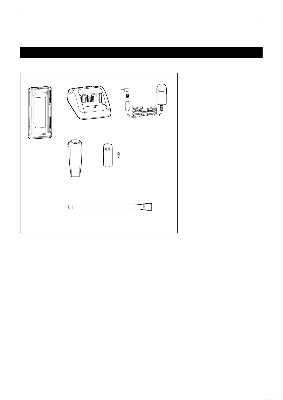
ACCESSORIES
Battery pack*
Belt clip* Connector cover
(with screws)
Battery charger* Power adapter*
* Not supplied, or the shape is different, depending on the transceiver’s version.
Flexible antenna
(This illustration is for the VHF type.)
1
Supplied accessories
The following accessories are supplied.
1-2
Page 5
ACCESSORIES
q
w
Battery release
button
1
Accessory attachments
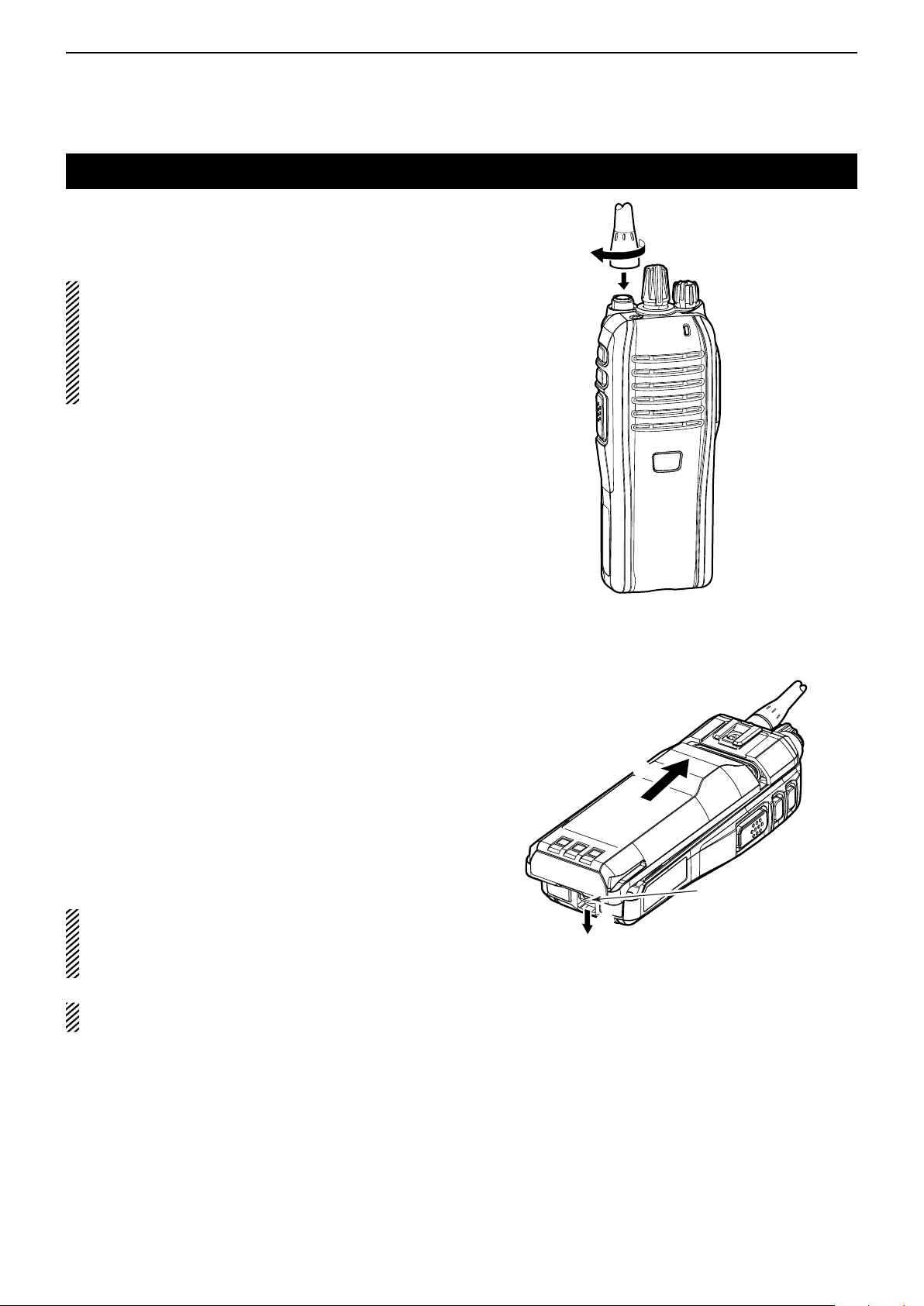
Flexible antenna D
Connect the supplied flexible antenna to the antenna
connector.
CAUTION:
• NEVER carry the transceiver by holding only the
antenna.
• DO NOT connect any antenna other than those
listed on the basic instructions.
• Transmitting without an antenna will damage the
transceiver.
Battery pack D
To attach the battery pack:
Slide the battery pack on the back of the transceiver in
the direction of the arrow (q), then lock it with the battery
release button.
• Slide the battery pack until the battery release button makes
a ‘click’ sound.
To remove the battery pack:
Push the battery release button in the direction of the
arrow (w), as shown to the right. The battery pack is
then released, and you can remove it.
NEVER remove or attach the battery pack when the
transceiver is wet or soiled. This may result in water
or dust getting into the transceiver/battery pack and
may damage the transceiver.
NOTE: Keep the battery pack terminals clean. It’s a
good idea to occasionally clean them.
1-3
Page 6
ACCESSORIES
Belt clip
w
q
Ta b
r
e
q
w
1
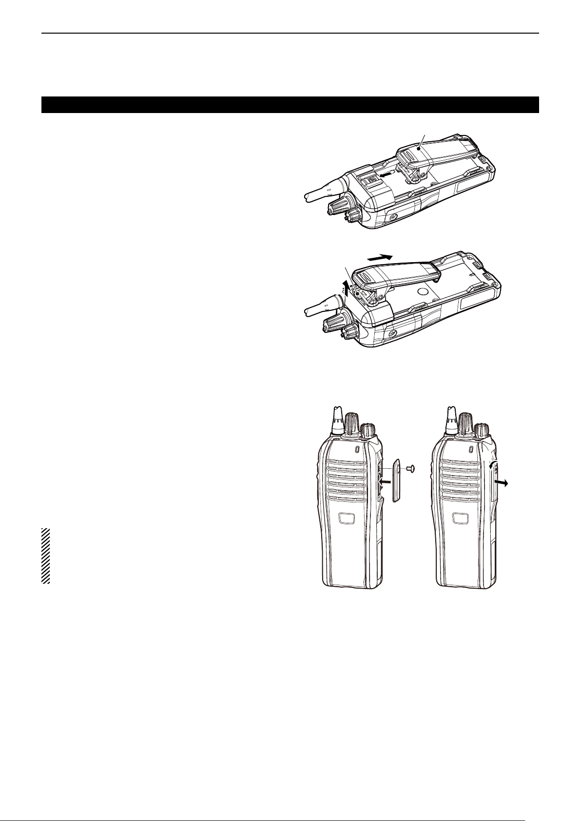
Accessory attachments (Continued)
Belt clip D
Before attaching or detaching the belt clip, remove the
battery pack if it is attached.
To attach the belt clip:
Slide the belt clip in the direction of the arrow until ➥
the belt clip locks and makes a ‘click’ sound.
To detach the belt clip:
Lift the tab up ( ➥ q), and slide the belt clip in the direc-
tion of the arrow (w).
Connector cover D
To attach the connector cover:
Place the connector cover over the multi-connector. q
(q)
Tighten the screw. ( w w)
To detach the connector cover:
Remove the screw using a Phillips screwdriver. ( q e)
Detach the connector cover to connect optional w
equipment. (r)
CAUTION:
Attach the connector cover when the optional ac-
cessory is not used. Otherwise, the terminals of the
multi-connector may be shorted, and this could damage the transceiver.
1-4
Page 7

Section 2
PANEL DESCRIPTION
Front, top and side panels ......................................................2-2
Status indicator .......................................................................2-3
Programmable function keys .................................................2-5
2-1
Page 8

PANEL DESCRIPTION
Connector
cover
2
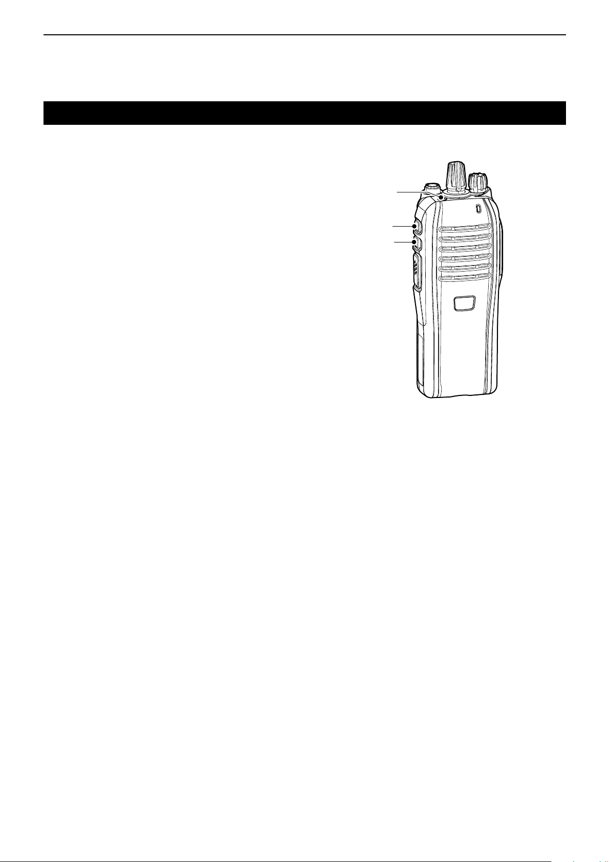
Front, top and side panels
o ANTENNA
CONNECTOR
i EMERGENCY
KEY
u UPPER KEY
y LOWER KEY
t PTT SWITCH
q ROTARY SELECTOR
Rotate to select the preprogrammed memory chan-
nels or scan lists, depending on the preprogramming.
w VOLUME CONTROL [VOL]
Rotate to turn the power ON or OFF, and adjust the
audio level.
e STATUS INDICATOR (pp. 2-3, 2-4)
Lights red while transmitting. ➥
Lights green while receiving a signal, or when the ➥
squelch is open.
Lights/blinks orange when the matched 2/5-tone ➥
code is received, depending on the presetting.
q ROTARY
SELECTOR
w VOLUME
CONTROL
e STATUS INDICATOR
Speaker
r MULTI
CONNECTOR
Microphone
t PTT SWITCH [PTT]
Hold down to transmit; release to receive.
y LOWER KEY [Lower]
u UPPER KEY [Upper]
Desired functions can be preset. (p. 2-5)
i EMERGENCY KEY [Emer]
Desired functions can be preset. (p. 2-5)
o ANTENNA CONNECTOR
Connect the antenna.
r MULTI CONNECTOR
Connect optional accessory.
CAUTION:
Attach the connector cover
when the optional accessory is not used. Otherwise,
the terminals of the multiconnector may be shorted,
and this could damage the
transceiver.
2-2
Page 9
PANEL DESCRIPTION
R
G
O
O O
O O O
O O O
O G
O R
O
O
G G
G G
G G G G
R R
R R R R
2
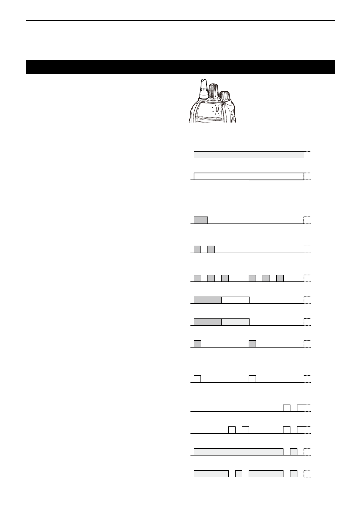
Status indicator
The status indicator indicates the various parameters
of the transceiver as follows;
(Reference: R is Red, G is Green, O is Orange)
• TX:
Lights Red while transmitting.
• RX busy:
On an analog channel, lights Green when in the
noise squelch opens.
On a digital or mixed channel, lights Green while de-
tecting a frame synchronization.
• Call LED:
Turns ON when receiving a matched 2/5-tone, or re-
ceiving a Status or SDM (Short Data Message) call.
• Call LED:
Blinks when receiving a matched 2/5-tone, or receiv-
ing a Status or SDM (Short Data Message) call.
• Call LED:
Blinks while waiting for a return signal.
• Success:
Blinks slowly when your call was successful.
• Call error:
Blinks slowly when your call failed, or was refused.
• Audible:
Blinks slowly after a return signal is received when in
the Audible mode*.
* Mute is released. (Received signal will be heard.)
• Fast, Slow or Voting scan:
Blinks when scanning for a channel to search for a
signal.
• Low Battery 1:
You should charge the battery soon. (blinks slowly)
• Low Battery 2:
You must charge the battery. (blinks fast)
• TX low Battery 1:
Low Battery was detected in the TX mode.
• TX low Battery 2:
Very Low Battery was detected
in the
TX mode.
2-3
Page 10

PANEL DESCRIPTION
R O O O
G O R G O R G O R G O R
G O R G O R G O R G O R
R O R O R O R O R O R O R O R O
R O GR O G
2
Status indicator (Continued)
• Channel Error:
Blinks when a non-programmed channel is select-
ed.
• Power ON:
Blinks at transceiver startup.
• TX inhibit:
Blinks while in the TX inhibit mode such as when the
TOT or Lockout function is activated.
• Emergency:
Blinks when an Emergency call was received.
• Emergency Locator Ringer Siren:
Blinks while the Emergency locator, Ringer or Siren
is activated.
2-4
Page 11
PANEL DESCRIPTION
2
Programmable function keys
The programmable key functions can be assigned to
the [Upper], [Lower] and [Emer] programmable function keys.
EMERGENCY
KEY
UPPER KEY
LOWER KEY
2-5
Page 12

PANEL DESCRIPTION
2
Programmable function keys (Continued)
The following functions can be assigned to the [Upper],
[Lower] and [Emer] programmable function keys.
SCAN
Push to start and cancel scanning.
• When the scan started with the Power ON Scan or Auto
Scan function, push to pause the scan. The paused scan
resumes after the specified time period has passed.
PRIORITY A CHANNEL, PRIORITY B CHANNEL
Push to select the Priority A or Priority B channel.
PRIORITY A CHANNEL (REWRITE),
PRIORITY B CHANNEL (REWRITE)
Push to select the Priority A or Priority B channel. ➥
Hold down [Prio A (Rewrite)] or [Prio B (Rewrite)] ➥
for 1 second to assign the operating channel to the
Priority A or Priority B channel, respectively.
MEMORY CHANNELS 1, 2, 3, 4
Push to directly select memory channel 1, 2, 3 or 4, if
programmed.
LONE WORKER (p. 3-13)
Hold down for 1 second to turn ON the Lone Worker ➥
function.
• When the Lone Worker function is turned ON, and no
operation is performed for the specified time period, the
Emergency function is automatically turned ON.
Push to turn OFF the Lone Worker function. ➥
MONITOR, MONITOR (AUDIBLE)
Push to turn the CTCSS (DTCS) or 2/5-tone squelch ➥
Mute ON or OFF.
• Only during LMR operation, push to open any squelch
functions, or deactivate any mute functions.
• Only during PMR operation, push to activate one or two
of the following functions on each channel.
- Hold down to unmute the channel (Audible mode).
- Push to mute the channel (Inaudible mode).
- Push to send a ‘reset code’ after the communication is
finished.
NOTE: The unmute condition may automatically
return to the mute condition, after a specified time
period.
Depending on the presetting, holding down this key ➥
for 1 second cancels a scan.
HIGH/LOW (p. 3-12)
Select the transmit output power level temporarily or
permanently, depending on the presetting.
TALK AROUND
Hold down for 1 second to turn ON the Talk Around ➥
function.
• The Talk Around function equalizes the transmit frequency to the receive frequency for transceiver-to-transceiver
communication.
Push to turn OFF the Talk Around function. ➥
DTMF AUTODIAL
Push to transmit a programmed DTMF code.
RE-DIAL
Push to transmit the last-transmitted DTMF code.
NOTE: TX memories are cleared after turning OFF
the transceiver.
WIDE/NARROW
Push to select the IF bandwidth between Wide, Mid*
or Narrow.
* Depending on the presetting, the Mid channel width may not
be selectable.
CALL, CALL A, CALL B
Push to transmit a 2/5-tone code.
• Tone call transmission may be necessary before you call
another station, depending on your signalling system.
• [Call A] and/or [Call B] keys may be selectable when your
system employs selective ‘Individual/Group’ calls.
EMERGENCY
Hold down for specified time period to transmit an
emergency call.
• The emergency call transmits with beeps, and the status
indicator lights red.
• The transceiver can transmit an emergency call without the
beep sounding and the status indicator lighting.
• If you want to cancel the emergency call, hold down the key
again before transmitting the call.
• The emergency call is transmitted one time only, or repeat-
edly until receiving an acknowledgement signal, or until the
power is turned OFF.
When a matched 5-tone code signal is received, the emer-
gency function can be cancelled, depending on the presetting. (PMR operation only)
LOCK
Hold down to electronically lock all programmable keys
except [Moni(Audi)], [Call] (including Call A and Call B),
[Emergency], [Surveillance] and [Lone Worker].
2-6
Page 13

PANEL DESCRIPTION
2
Programmable function keys (Continued)
SURVEILLANCE
Hold down for 1 second to turn ON the Surveillance ➥
function.
• When this function is turned ON, the beep is not heard
and the status indicator does not light when a signal is
received, or a key is pushed.
Push to turn OFF the Surveillance function. ➥
SIREN
Hold down for 1 second to emit a siren sound.
This function can be used for situations other than an
emergency alert, such as a security alarm for example.
The transceiver emits the siren sound until the power
is turned OFF.
SCRAMBLER
Hold down for 1 second to turn ON the Voice Scram- ➥
bler function while operating in the digital mode.
Push to turn OFF the Voice Scrambler function. ➥
ANNOUNCE
Push to turn the Channel Announce function ON or
OFF.
• When this function is turned ON, the transceiver announces
the position of [ROTARY SELECTOR] between 1 and 16
when rotating [ROTARY SELECTOR] to a desired number.
2-7
Page 14

Section 3
BASIC OPERATION
Turning ON the power .............................................................3-2
Selecting a channel .................................................................3-3
Selecting a channel D .................................................................3-3
Voting Operation D ......................................................................3-3
Priority A channel selection D .....................................................3-3
Call procedure .........................................................................3-4
Receiving and transmitting ....................................................3-5
Transmitting notes D ...................................................................3-5
DTMF transmission D .................................................................3-6
Receiving a Stun, Kill and Revive command D ...........................3-6
Setting the Beep function .......................................................3-7
Setting the beep level ..............................................................3-8
Setting the ringer level ............................................................3-9
Setting the microphone gain ..................................................3-10
Setting the squelch level ........................................................3-11
Output power level selection ..................................................3-12
Emergency Call ........................................................................3-13
Lone Worker Emergency Call D ..................................................3-13
Man Down Emergency Call D .....................................................3-13
3-1
Page 15

BASIC OPERATION
[VOL]
3
Turning ON the power
Prior to using the battery pack for the first time, or after
not using it for a long time, you must fully charge the
pack for optimum battery life and operation. See BASIC
INSTRUCTIONS that are provided with the transceiver
for details.
Rotate [VOL] to turn ON the power. ➥
3-2
Page 16

BASIC OPERATION
3
Selecting a channel
Selecting a channel D
To select the desired operating channel:
Rotate [ROTARY SELECTOR]. ➥
Push one of the memory channel keys, [MR-CH 1] ➥
to [MR-CH 4].
Push [Prio A], [Prio B], [Prio A (Rewrite)] or [Prio B ➥
(Rewrite)].
AUTOMATIC SCAN TYPE:
Selecting a channel is not necessary. When turning ON
the power, the transceiver automatically starts scanning. Scanning stops when a signal is detected.
Voting Operation D
The transceiver automatically starts scanning when a
zone, specified for the voting operation, is selected.
The voting scan detects the signal of the repeater and
automatically selects the strongest station.
Priority A channel selection D
When one of the following operations is performed, the
transceiver automatically selects the Priority A channel.
• Turning ON the power
The Priority A channel is selected each time the transceiver power is turned ON.
• Auto reset
The Priority A channel is selected when the Auto Reset
timer ends.
3-3
Page 17

BASIC OPERATION
Selective calling
Non-selective calling
3
Call procedure
When your system employs tone signalling (excluding
CTCSS and DTCS), the tone call procedure may be
necessary prior to voice transmission. The tone signalling that is employed in the transceiver may be a selective calling system, which allows you to call only specific station(s), and prevents unwanted stations from
contacting you.
Select a desired TX code channel or 2/5-tone code, q
according to your System Operator’s instructions.
• This may not be necessary, depending on the programming.
Push [Call] (assigned to [Upper], [Lower] or [Emer]). w
(p. 2-6)
After transmitting a 2/5-tone code, the remainder of e
your communication can be carried out normally.
3-4
Page 18

BASIC OPERATION
3
Receiving and transmitting
Receiving:
Rotate [VOL] to turn ON the power. q
Select a channel. w
Rotate [ROTARY SELECTOR]. ➥
Push one of the memory channel keys, [MR-CH 1] ➥
to [MR-CH 4].
When receiving a call, adjust the audio output to a e
comfortable listening level.
NOTE: When a matched RX code signal is received,
the transceiver automatically transmits its microphone audio for a specified time period, depending
on the presetting.
Transmitting:
CAUTION: Transmitting without an antenna will damage the transceiver. See page 1-3 for antenna attachment.
Wait for the channel to become clear to avoid interference.
While holding down [PTT], speak into the micro- q
phone at a normal voice level.
Release [PTT] to receive. w
Transmitting notes D
• Transmit inhibit function
The transceiver has several inhibit functions, which re-
strict transmission under the following conditions:
- The channel is muted. (PMR operation only)
- The channel is busy.
- A signal with an unmatched (or matched) CTCSS (or
DTCS) tone is received.
- The selected channel is a ‘receive only’ channel.
• Time-out timer
After continuously transmitting longer than the preprogrammed time period, the time-out timer activates, and
stops further transmitting.
• Penalty timer
Once the time-out timer activates, transmitting is further
inhibited for a time period determined by the penalty
timer.
• PTTID call
The transceiver automatically sends the ID code (5tone, DTMF or BIIS operations) when [PTT] is pushed
(beginning of the transmission) and/or released (end of
transmission), depending on the presetting.
NOTE: To maximize the readability of your signal:
1. Pause briefly after pushing [PTT].
2.
Hold the microphone 5 to 10 cm (2 to 4 inches) from
your mouth, then speak at a normal voice level.
3-5
Page 19

BASIC OPERATION
3
Receiving and transmitting (Continued)
DTMF transmission D
If the transceiver has [DTMF Autodial] assigned to it,
the automatic DTMF transmission function is usable.
Push [DTMF Autodial] to transmit the DTMF code. ➥
Receiving a Stun, Kill and Revive command D
The dispatcher can send a signal that will stun, kill or
revive your transceiver.
When the Stun command is received, a beep sounds*,
and the transceiver becomes unusable. Receiving a
Revive command is necessary to operate the transceiver again in this case.
When the Kill command is received, a beep sounds*,
and the transceiver becomes unusable. Cloning the
transceiver is necessary to operate the transceiver
again in this case.
* Depending on the presetting.
3-6
Page 20

BASIC OPERATION
3
Setting the Beep function
The Beep function can be turned ON or OFF. When it is
OFF, the channel announcement is also turned OFF.
NOTE: You should turn ON the Beep function when
you set the microphone gain or the squelch level to
check the current level setting with the beep sounding. (pp. 3-10, 3-11)
[ROTARY SELECTOR]
Rotate [VOL] to turn OFF the transceiver power. q
Set [ROTARY SELECTOR] to any channel other w
than Channel 16.
While holding down [Lower], rotate [VOL] to turn ON e
the power to enter the Beep level adjustment mode.
Push [Lower] to turn the Beep function ON or OFF. r
• When a beep sounds after pushing [Lower], the Beep
function is ON. When no beep sounds after pushing
[Lower], the Beep function is OFF.
• If desired, push [Upper] to adjust the Beep level. See
page 3-8 for details.
Rotate [VOL] to turn OFF the power to exit the Beep t
level adjustment mode.
NOTE: This operation may not be available, depending on the presetting.
[VOL]
[Upper]
[Lower]
3-7
Page 21

BASIC OPERATION
2
5
4
3
1
5 (Linked)
4 (Linked)
3 (Linked)
2 (Linked)
1 (Linked)
Pushing
[Upper]
3
Setting the beep level
You can adjust the beep level between 1 and 5, or 1
(linked) and 5 (linked).
When a linked option is selected, you can adjust the
beep level by rotating [VOL].
Rotate [VOL] to turn OFF the transceiver power. q
Set [ROTARY SELECTOR] to any channel other w
than Channel 16.
While holding down [Lower], rotate [VOL] to turn e
ON the power and enter the beep level adjustment
mode.
Push [Upper] to change the beep level as shown to r
the right.
• A beep sounds every time you push [Upper]. Therefore,
you can determine the current level setting by the increasing loudness of the beep that sounds.
• To determine if you have selected a linked level, set [VOL]
to minimum, then push [Upper] repeatedly, listening for
the loudest beep (level 5). Pushing [Upper] once after the
loudest beep will select 1 (Linked). Repeatedly push [Upper] to select the desired linked level.
Rotate [VOL] to turn OFF the power to exit the beep t
level adjustment mode.
NOTE: This operation may not be available, depending on the presetting.
[ROTARY SELECTOR]
[VOL]
[Upper]
[Lower]
3-8
Page 22

BASIC OPERATION
2
5
4
3
1
5 (Linked)
4 (Linked)
3 (Linked)
2 (Linked)
1 (Linked)
Pushing
[Lower]
Pushing
[Upper]
3
Setting the ringer level
You can adjust the ringer level between 1 and 5, or 1
(linked) and 5 (linked).
When a linked option is selected, you can adjust the
ringer level by rotating [VOL].
Rotate [VOL] to turn OFF the transceiver power. q
Set [ROTARY SELECTOR] to Channel 16. w
While holding down [Lower], rotate [VOL] to turn e
ON the power and enter the ringer level adjustment
mode.
Push [Upper] to increase, or push [Lower] to de- r
crease the ringer level as shown to the right.
• A beep sounds after pushing [Upper] or [Lower]. Therefore, you can determine the current level setting by the
increasing loudness of the beep that sounds.
• To determine if you have selected a linked level, set [VOL]
to minimum, then push [Upper] up to 10 times, listening
for the loudest beep (level 5). Pushing [Upper] once after
the loudest beep will select 1 (Linked). Repeatedly push
[Upper] or [Lower] to select the desired linked level.
Rotate [VOL] to turn OFF the power to exit the ringer t
level adjustment mode.
NOTE: This operation may not be available, depending on the presetting.
[ROTARY SELECTOR]
[VOL]
[Upper]
[Lower]
3-9
Page 23

BASIC OPERATION
3
Setting the microphone gain
Higher levels make the microphone more sensitive to
the user’s voice.
Rotate [VOL] to turn OFF the transceiver power. q
Set [ROTARY SELECTOR] to Channel 16. w
While holding down [Upper], rotate [VOL] to turn ON e
the power and enter the microphone gain adjustment mode.
Push [Upper] or to increase, or push [Lower] to de- r
crease the microphone gain.
• The adjustable range is 1 (minimum) to 4 (maximum).
• A beep sounds after pushing [Upper] or [Lower].
An error beep sounds if you try to exceed the adjustable
range.
NOTE: The Beep function should be turned ON. (p. 3-4)
Rotate [VOL] to turn OFF the power to exit the micro- t
phone gain adjustment mode.
[ROTARY SELECTOR]
[VOL]
[Upper]
[Lower]
NOTE: This operation may not be available, depend-
ing on the presetting.
3-10
Page 24

BASIC OPERATION
3
Setting the squelch level
The squelch circuit mutes the received audio signal,
depending on the signal strength.
Rotate [VOL] to turn OFF the transceiver power. q
Set [ROTARY SELECTOR] to any channel other w
than Channel 16.
While holding down [Upper], rotate [VOL] to turn ON e
the power and enter the squelch level adjustment
mode.
Push [Upper] to increase the squelch level (tight r
squelch), or push [Lower] to decrease the squelch
level (loose squelch).
• The adjustable range is 0 (loose squelch) to 9 (tight
squelch).
• A beep sounds after pushing [Upper] or [Lower]. An error
beep sounds if you try to exceed the adjustable range.
NOTE: The Beep function should be turned ON. (p. 3-4)
Rotate [VOL] to turn OFF the power to exit the t
squelch level adjustment mode.
[ROTARY SELECTOR]
[VOL]
[Upper]
[Lower]
NOTE: This operation may not be available, depend-
ing on the presetting.
3-11
Page 25

BASIC OPERATION
3
Output power level selection
If the transceiver has [High/Low] assigned to it, the
transmit output power level can be selected, depending
on the presetting.
When the battery voltage drops to a low power level and
the status indicator indicates “Low Battery 2,” the output
power automatically switches to “Low 1.” (p. 2-3)
Push [High/Low] to select the transmit output power ➥
level.
• One beep sounds when “Low 1” is selected.
• Two beeps sound when “Low 2” is selected.
• Three beeps sound when “High” is selected.
3-12
Page 26

BASIC OPERATION
3
Emergency Call
When [Emergency] is held down for the specified time
period*, the emergency signal is transmitted once, or
repeatedly, on the specified emergency channel.
* Depending on the presetting.
A repeat emergency signal is automatically transmitted
until you turn OFF the power.
Depending on the preprogrammed settings, receiving a
matching 5-tone code cancels the transmission.
When no emergency channel is specified, the signal is
transmitted on the previously selected channel.
If you want to cancel the emergency call, hold down
[Emergency] again before transmitting the call.
If your transceiver is programmed for Silent operation,
you can transmit an Emergency call without the beep
sounding and the status indicator lighting.
IMPORTANT: We recommend you set an emergency channel individually to provide for reliable emergency call operation.
NOTES
Depending on the presetting, the following functions
are automatically activated.
Lone Worker Emergency Call D
When the Lone Worker function is turned ON, and no
operation is performed for the specified time period*,
the transceiver enters the emergency mode, and then
the countdown for the emergency call transmission
starts.
After the specified time period* has passed, an emergency call is automatically transmitted once, or repeatedly*.
If someone operates the transceiver before the call is
transmitted, the transceiver exits the emergency mode,
and the emergency call is cancelled.
* Depending on the presetting.
Hold down [Lone Worker] for 1 second to turn ON q
the Lone Worker function.
w Push [Lone Worker] to turn OFF the Lone Worker
function.
Man Down Emergency Call D
When the transceiver has been left in a horizontal position for the preprogrammed time period, the transceiver
enters the emergency mode, and then the countdown
for the emergency call transmission starts.
After the preprogrammed time period, an emergency
call is automatically transmitted once, or repeatedly,
depending on the pre-programmed settings.
• Auto TX function
After the emergency call transmission, audio from the
microphone is automatically transmitted for a specified time period.*
• Auto RX function
After the emergency call transmission, the transceiver
stands by in the Audible mode for the specified time
period.*
* Depending on the presetting.
If the transceiver is placed in a vertical position before
the first transmission, the transceiver exits the emergency mode and the emergency call is cancelled.
3-13
Page 27

Section 4
dPMR™ OPERATION
dPMR™ operation .....................................................................4-2
Receiving a call ........................................................................4-3
Receiving an Individual call D .....................................................4-3
Receiving a Group call D ............................................................4-3
Receiving a Stun, Kill or Revive D ..............................................4-3
Receiving a Status Polling call D ................................................4-3
Receiving an Ambience Listening call D .....................................4-3
Receiving an Emergency call D ..................................................4-3
Talk back function D ....................................................................4-3
Transmitting a call ...................................................................4-4
Transmitting a Voice call D ..........................................................4-4
Transmitting an Emergency call D ..............................................4-4
Status message transmission ................................................4-5
Scrambler function ..................................................................4-6
4-1
Page 28

dPMR™ OPERATION
4
dPMR™ operation
The transceiver providing digital Private Mobile Radio
(dPMR™) operation meets the 6.25 kHz bandwidth requirements for narrow band operation. This increases
the efficiency of channel allocation and use of the spectrum.
NOTE: During dPMR™ operation, BIIS 1200 opera-
tion is disabled.
4-2
Page 29

dPMR™ OPERATION
4
Receiving a call
Receiving an Individual call D
When an Individual call is received: q
• The transceiver will automatically transmit a return sig-
nal.
• The status indicator blinks orange.
• Beeps sound and the mute is released.
Hold down [PTT], then speak into the microphone. w
Release [PTT] to receive. e
After the communication is finished, push [Clear] to r
send a ‘Disconnect’ signal to terminate the connection.
NOTE: The status indicator and Beeps may differ,
depending on the presetting.
Receiving a Group call D
When a Group call is received: q
• The status indicator blinks orange.
• Beeps sound and the mute is released.
Hold down [PTT], then speak into the microphone. w
NOTE: Only one station is allowed to speak at the
same time.
Release [PTT] to receive. e
After the communication is finished, push [Clear] to r
send a ‘Disconnect’ signal to terminate the connection.
NOTE: The status indicator or Beeps may differ, depending on the presetting.
Receiving a Stun, Kill or Revive D
If an individual Stun or Kill call is received, the transceiver will automatically transmit an acknowledgement,
and then you cannot receive* or transmit.
* Reception may be available, depending on the preset-
ting of the received stun command.
When a Stun command is received: ➥
• The transceiver cannot be operated until the individual
revive call is received or until data cloning is performed.
• Even if [ROTARY SELECTOR] is changed, the transceiver will stay on the same channel the Stun command
received on.
When a Kill command is received: ➥
• The status indicator alternately blinks red and green.
• The transceiver cannot be operated until data cloning is
performed.
NOTE: Depending on the presetting, the transceiver
may ignore the Stun, Revive and Kill commands, that
are from a non-specified station.
Receiving a Status Polling call D
If a Status Polling call is received, the transceiver will
automatically transmit its current status.*
Receiving an Ambience Listening call D
If an Individual call with an Ambience Listening command is received from a specified station, the transceiver will automatically transmit its microphone audio.*
*Depending on the presetting.
NOTE: If the transceiver receives an Ambience Listening command from a station other than the specified one, the call will be ignored, and the transceiver
will not transmit its microphone audio.
Receiving an Emergency call D
When an Emergency call is received: q
• The transceiver will automatically transmit a return signal.
• The status indicator blinks orange.
• Beeps sound and the mute is released.
Push [Clear] to return to the standby mode. w
Talk back function D
The Talk Back function allows you to select the same
call mode (Analog or Digital) as the received call.
NOTE: When this function is not activated, the transceiver always transmits analog signals on “MixedAnalog” channels, and digital signals on “Mixed-Digital” channels.
• On these channels, the transceiver can receive both
analog and digital signals, regardless of the Talk Back
function.
4-3
Page 30

dPMR™ OPERATION
4
Transmitting a call
dPMR™ operation allows you to make a call to a specific station (Individual call) or to a particular group
(Talkgroup call). Other digital mode transceivers on the
channel will not receive a call that does not match their
individual or talkgroup ID and/or CC.
Transmitting a Voice call D
Rotate [ROTARY SELECTOR], or push one of the q
memory channel keys, [MR-CH 1] to [MR-CH 4], to
select a desired channel, Individual ID or Talkgroup
ID, depending on the presetting.
Push [PTT] or [Call] to make a Voice call. w
• The status indicator lights red while transmitting.
• The status indicator fast blinks orange.
• After an acknowledgement is received, the status indica-
tor slowly blinks orange in the Audible mode, or it goes
OFF when no acknowledgement is received.
Hold down [PTT], then speak at your normal voice e
level.
• The status indicator lights red while transmitting.
Release [PTT] to receive. r
After you finish your communication, push [Clear] to t
send a ‘Disconnect’ signal to terminate the connection.
Transmitting an Emergency call D
When [Emergency] is held down for the specified time
period, the emergency signal (digital command) is transmitted once or repeatedly* on the specified emergency
channel. When no emergency channel is specified, the
signal is transmitted on the operating channel.
* When the Repeat Cancel function is ON, the transceiver
cancels repeating after receiving a return signal.
When the Repeat Cancel function is OFF, the transceiver repeats calling according to the number of repeat cycles, even after receiving a return signal.
Individual or Talkgroup call types of emergency calls
can be pre-set. If the call type is not preset, the default
or selected call type is used.
If you want to cancel the emergency call, hold down
[Emergency] again before transmitting the call.
If your transceiver is programmed for Silent operation,
you can transmit an Emergency call without the beep
sounding and the status indicator lighting.
The transceiver can also be programmed to keep the
microphone open during an emergency call, so others
can monitor the situation.
IMPORTANT: We recommend you set an emergency channel individually to provide the certain emergency call operation.
NOTE: If the Digital Request Ack function is activated, the transceiver transmits the emergency call with
a request to send back a return signal.
4-4
Page 31

dPMR™ OPERATION
4
Status message transmission
The status message can automatically be transmitted.
The status message is transmitted when the transceiver is turned ON or OFF.
- Select a status message to be transmitted in ‘Power ON
Status’ or ‘Power OFF Status’ items, respectively.
- Select a target station ID in ‘Power Status ID’.
4-5
Page 32

dPMR™ OPERATION
4
Scrambler function
The voice scrambler function provides private communication between stations while operating in the digital
mode.
Hold down [Scrambler] for 1 second to turn ON the q
Scrambler function.
Push [Scrambler] to turn OFF the Scrambler func- w
tion.
4-6
Page 33

Section 5
SPEAKER MICROPHONE
Optional HM-203EX .................................................................5-2
Description D ..............................................................................5-2
To attach D ..................................................................................5-2
5-1
Page 34

SPEAKER MICROPHONE
Speaker
Belt clip
Microphone
PTT SWITCH
Hold down to
transmit, release
to receive.
Tu rn OFF the transceiver power when
connecting or disconnecting the microphone.
Tu rn OFF the power
5
Optional HM-203EX
Description D
NEVER immerse the connector in water. If the con-
nector becomes wet, be sure to dry it BEFORE connecting it to the transceiver.
NOTE: The microphone is located at the top of the
speaker microphone, as shown in the diagram above.
To maximize the readability of your transmitted signal (voice), hold the microphone approximately 5 to
10 cm (2 to 4 inches) from your mouth, and speak at
a normal voice level.
To attach D
BE SURE to turn OFF the power before attaching.
Attach the connector of the speaker microphone into ➥
the multi connector on the transceiver, and tighten
the screw.
IMPORTANT: KEEP the connector cover attached
to the transceiver when the speaker microphone is
not in use. (p. 1-4)
Water will not get into the transceiver even if the cover is not attached, however, the terminals (pins) will
become rusty, or the transceiver will function abnormally if the connector becomes wet.
CAUTION: Attach the
multi connector snugly,
but do not overtighten.
A loose connection will
allow water intrusion into
the connector. A overtightened connector will
damage the connector
pins in the transceiver.
5-2
Page 35

A-7166-4EX
© 2014 Icom Inc.
1-1-32 Kamiminami, Hirano-ku, Osaka 547-0003, Japan
 Loading...