

Icom iC-F3161DT Instruction Manual

INSTRUCTION MANUAL
VHF TRANSCEIVER
iF3161DT
This device complies with Part 15 of the FCC Rules. Operation
is subje ct to the c ondition that this dev ice does not cause
harmful interference.

IMPORTANT
PRECAUTIONS
READ ALL INSTRUCTIONS carefully and com-
pletely before using the transceiver.
SAVE THIS INSTRUCTION MANUAL — This
instruction manual contains important oper ating instructions
for the IC-F3161DT VHF TRANSCEIVER.
• See the operating guide for details of Digital, BIIS, MDC
and LTR
• This instruction manual includes some functions which
are usable only when they are pre-programmed by your
dealer. Ask your dealer for details.
®
system operations. Ask your dealer for details.
EXPLICIT DEFINITIONS
WORD DEFINITION
RDANGER!
RWARNING!
CAUTION
NOTE
i
Personal death, serious injury or an explosion may occur.
Personal injury, fire hazard or electric
shock may occur.
Equipment damage may occur.
If disregarded, inconvenience only. No risk
of personal injury, fire or electric shock.
R DANGER! NEVER short the terminals of the bat-
tery pack.
R DANGER! Use and charge only specified Icom battery
packs with Icom radios or Icom chargers. Only Icom battery
packs are tested and approved for use with Icom radios or
charged with Icom chargers. Using third-party or counterfeit
battery packs or chargers may cause smoke, fire, or cause
the battery to burst.
R WARNING! NEVER hold the transceiver so that
the antenna is very close to, or touching exposed parts of
the body, especially the face or eyes, while transmitting. The
transceiver will perform best if the microphone is 2 to 4 in. (5
to 10 cm) away from the lips and the transceiver is vertical.
R WARNING! NEVER operate the transceiver with
a headset or other audio accessories at high volume levels.
Hearing experts advise against continuous high volume operation. If you experience a ringing in your ears, reduce the
volume level or discontinue use.
R WARNING! NEVER operate the transceiver while
driving a vehicle. Safe driving requires your full attention—
anything less may result in an accident.

CAUTION: MAKE SURE
battery pack are securely attached to the transceiver, and that
the antenna and battery pack are dry before attachment.
Exposing the inside of the transceiver to water will result in
serious damage to the transceiver.
the flexible antenna and
DO NOT use harsh solvents such as benzine or alcohol
when cleaning, as they will damage the transceiver surfaces.
BE CAREFUL! The transceiver will become hot when
operating it continuously for long periods of time.
1
2
3
4
5
6
DO NOT operate the transceiver near unshielded electri-
cal blasting caps or in an explosive atmosphere.
DO NOT push [PTT] when not actually intending to trans-
mit.
DO NOT use or place the transceiver in direct sunlight or
in areas with temperatures below +22°F (–30°C) or above
+140°F (+60°C).
The basic operations, transmission and reception of the
transceiver are guaranteed within the specified operating
temperature range. However, the LCD display may not operate correctly, or show an indication in the case of long hours
of operation, or after being placed in extremely cold areas.
DO NOT modify the transceiver. The transceiver warranty
does not cover any problems caused by unauthorized modification.
KEEP the transceiver away from the heavy rain, and never
immerse it in the water. The transceiver meets IP55* requirements for dust-protection and water jet resistance.
However, once the transceiver has been dropped, dust-protection and water jet resistance cannot be guaranteed due
to the fact that the transceiver may be cracked, or the waterproof seal damaged, etc.
* Only when the supplied battery pack, flexible antenna and connec-
tor cover are attached.
MAKE SURE to turn the transceiver power OFF before
connecting the supplied/optional equipment.
Icom, Icom Inc. and the Icom logo are registered trademarks of Icom Incorporated (Japan) in Japan, the United States, the United Kingdom, Germany,
France, Spain, Russia and/or other countries.
LTR is a registered trademark of the E.F.Johnson Company.
All other products or brands are registered trademarks or trademarks of their
respective holders.
7
8
9
10
11
12
13
14
15
16
ii

VOICE CODING TECHNOLOGY
FCC INFORMATION
The AMBE+2™ voice coding Technology embodied in this
product is protected by intellectual property rights including
patent rights, copyrights and trade secrets of Digital Voice
Systems, Inc. This voice coding Technology is licensed
solely for use within this Communications Equipment.
The user of this Technology is explicitly prohibited from
attempting to extract, remove, decompile, reverse engineer,
or disassemble the Object Code, or in any other way convert
the Object Code into a human-readable form. U.S. Patent
Nos.
#5, 8 7 0,40 5 , #5, 8 2 6,2 2 2 , #5 , 7 54,9 7 4 , #5 , 7 01, 3 9 0 ,
#5, 7 1 5,36 5 , #5, 6 4 9,0 5 0 , #5 , 6 30,0 1 1 , #5 , 5 81, 6 5 6 ,
#5,517,5 11, #5,491,77 2, #5,247,57 9, #5,226, 084 and
#5,195,166.
iii
• FOR CLASS B UNINTENTIONAL RADIATORS:
This equipment has been tested and found to comply with
the limits for a Class B digital device, pursuant to part 15 of
the FCC Rules. These limits are designed to provide reasonable protection against harmful interference in a residential
installation. This equipment generates, uses and can radiate
radio frequency energy and, if not installed and used in accordance with the instructions, may cause harmful interference to radio communications. However, there is no guarantee that interference will not occur in a particular installation.
If this equipment does cause harmful interference to radio or
television reception, which can be determined by turning the
equipment off and on, the user is encouraged to try to correct the interference by one or more of the following measures:
• Reorient or relocate the receiving antenna.
• Increase the separation between the equipment and re-
ceiver.
• Connect the equipment into an outlet on a circuit different from that to which the receiver is connected.
• Consult the dealer or an experienced radio/TV technician for help.
CAUTION: Changes or modifications to this transceiver, not
expressly approved by Icom Inc., could void your authority to
operate this transceiver under FCC regulations.

TABLE OF CONTENTS
IMPORTANT .......................................................................... i
EXPLICIT DEFINITIONS ....................................................... i
PRECAUTIONS ..................................................................... i
VOICE CODING TECHNOLOGY ........................................ iii
FCC INFORMATION ........................................................... iii
TABLE OF CONTENTS ....................................................... iv
1 ACCESSORIES ...........................................................1–2
■ Supplied accessories ...................................................1
■ Accessory attachments ................................................ 1
2 PANEL DESCRIPTION ................................................ 3–9
■ Front panel ................................................................... 3
■ Function display ...........................................................4
■ Programmable function keys ........................................5
3 BASIC OPERATION ................................................10–17
■ Turning power ON ......................................................10
■ Channel selection .......................................................11
■ Call procedure ............................................................12
■ Receiving and transmitting .........................................12
■ User Set Mode ...........................................................15
■ Emergency Transmission ...........................................15
■ Man Down Emergency Call ........................................15
■ Scrambler function .....................................................16
■ Stun function ..............................................................16
■ Automatic Key Lock function ...................................... 16
■ AAR Channel Entry .................................................... 17
4 BATTERY CHARGING ............................................18–22
■ Caution .......................................................................18
■ Optional battery chargers ...........................................20
5 BATTERY CASE ............................................................23
■ Optional battery case (BP-240) ..................................23
6 SPEAKER MICROPHONE ............................................24
■ Optional HM-169/170GP description .........................24
■ To attach ..................................................................... 24
7 SWIVEL BELT CLIP ................................................25–26
■ MB-93 contents .......................................................... 25
■ To attach ..................................................................... 25
■ To detach .................................................................... 26
8 OPTIONS .................................................................27–30
9 SAFETY TRAINING INFORMATION .......................31–32
1
2
3
4
5
6
7
8
9
10
11
12
13
14
15
16
iv
1
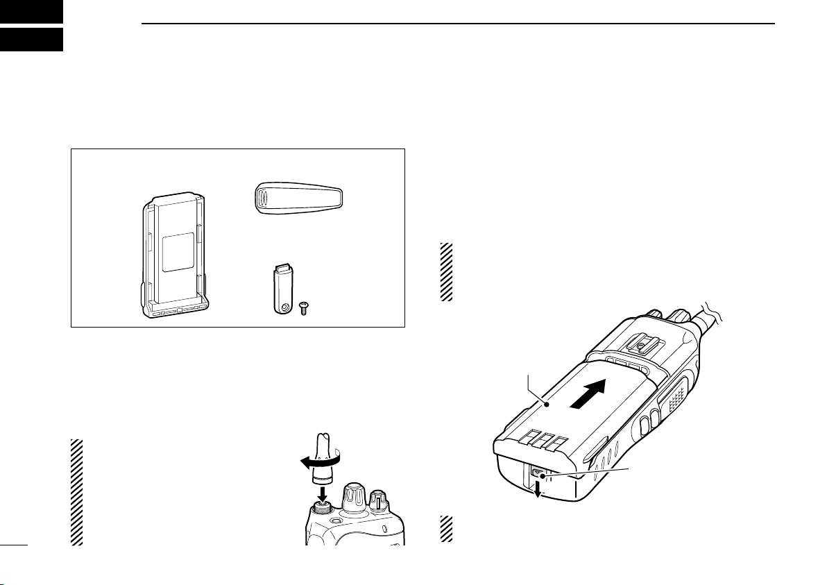
Battery pack Belt clip
Connector cover
(with screw)
q
w
Battery release
button
Battery pack
ACCESSORIES
1
■ Supplied accessories
The following accessories are supplied.
■ Accessory attachments
D Flexible antenna (Purchase separately)
Connect the optional antenna to the antenna connector.
CAUTION:
• NEVER carry the transceiver by
holding only the antenna.
• DO NOT connect the antenna oth-
er than listed on page 28.
• Transmitting without an antenna
may damage the transceiver.
D Battery pack
To attach the battery pack:
Slide the battery pack on the back of the transceiver in the direction of the arrow (q), then lock it with the battery release button.
• Slide the battery pack until the battery release button makes a ‘click’
sound.
To release the battery pack:
Push the battery release button in the direction of the arrow
(w) as shown below. The battery pack is then released.
NEVER release or attach the battery pack when the trans-
ceiver is wet or soiled. This may result water or dust getting into the transceiver/battery pack and may result in
them being damaged.
NOTE: Keep the battery pack terminals clean. It’s a good
idea to regularly clean them.
ACCESSORIES
q
w
q
w
Multiconnector
Connector
cover
q
w
1
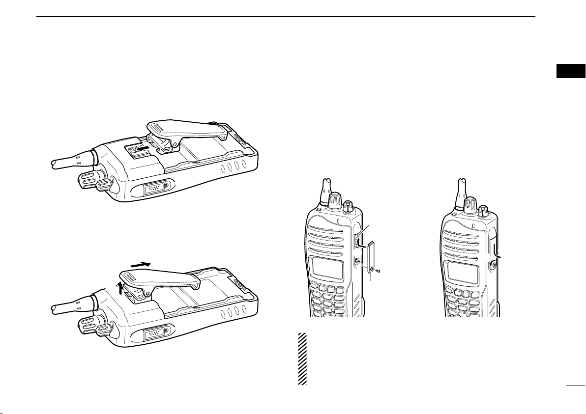
D Belt clip
To attach the belt clip:
q Remove the battery pack if it is attached.
w Slide the belt clip in the direction of the arrow, until the belt
clip is locked and makes a ‘click’ sound.
To remove the belt clip:
q Remove the battery pack if it is attached.
w Pinch the clip (q), and slide the belt clip in the direction of
the arrow (w).
D Connector cover
Attach the connector cover when the optional equipment is
not used.
To attach the connector
cover:
q Inser t t h e conn e c t o r
cover into the multi-connector.
w Tighten the screw.
CAUTION:
Attach the connector cover when the optional equipment
is not used. Otherwise the terminals of the multi-connector
may be shorted by metal object, etc., and this could damage the transceiver.
To detach the connector
cover:
q Unscrew the screw using
a phillips screwdriver.
w Detac h the connector
cover for the optional
equipment connector.
1
2
3
4
5
6
7
8
9
10
11
12
13
14
15
16
2
w
e
t
r
y
q
!1
!0
o
!2
u
i
Microphone
Speaker
2
PANEL DESCRIPTION
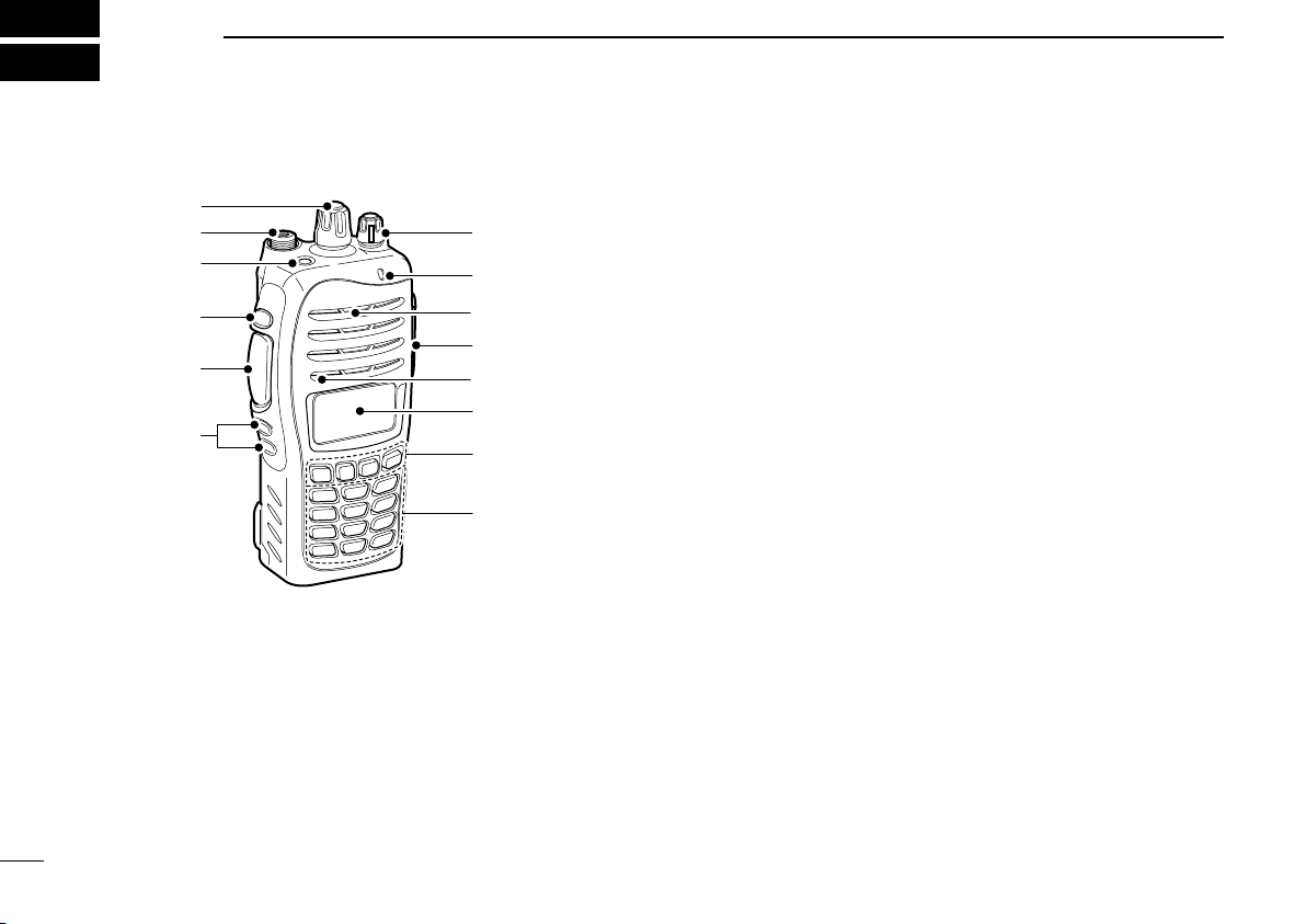
■ Front panel
r DEALER-PROGRAMMABLE KEY [Side1]
Desired function can be programmed by your dealer.
(p. 5)
t PTT SWITCH [PTT]
Push and hold to transmit; release to receive.
y DEALER-PROGRAMMABLE KEYS [Side2]/[Side3]
Desired function can be programmed independently by
your dealer. (p. 5)
u 10-KEYPAD (Depending on version)
The keypad allows you to enter digits to:
• Select memory channels
• Select tone channels
• Select DTMF codes (during transmit)
q ROTARY SELECTOR
Rotate to select the pre-programmed memory channels or
the operating zone. (Depending on the pre-setting)
w ANTENNA CONNECTOR
Connects the optional antenna. (p. 1)
e DEALER-PROGRAMMABLE KEY [EMR]
Desired function can be programmed by your dealer.
(p. 5)
3
• Set TX codes
• Start up with the password
i DEALER-PROGRAMMABLE KEYS [P0] to [P3]
Desired function can be programmed independently by
your dealer. (p. 5)
o FUNCTION DISPLAY (p. 4)
Displays a variety of information such as an operating
channel number/name, Set mode contents, DTMF code,
selected function, etc.
PANEL DESCRIPTION
Connector cover
NOTE: Attach the connector cover when the optional
equipment is not used.
See p. 2 for details.
SET
CALA TXCU
TXC
q t iuyrew
o
!0
2
!0 MULTI-CONNECTOR
Connect an optional equipment.
!1 BUSY/TRANSMIT INDICATOR
➥Lights green while receiving a signal, or when the
squelch is open.
➥Lights red while transmitting.
!2 VOLUME CONTROL [VOL]
Rotate to turn the power ON/OFF and adjusts the audio
level.
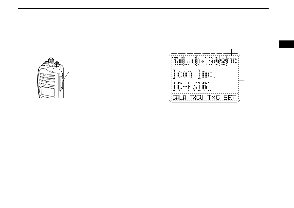
■ Function display
q SIGNAL STRENGTH INDICATOR
Indicates relative signal strength level.
w LOW POWER INDICATOR
Appears when low output power is selected.
e AUDIBLE INDICATOR
➥ Appears when the channel is in the ‘audible’ (unmute)
condition.
➥ Appears when the matched signal is received.
r COMPANDER INDICATOR
Appears when the compander function is activated.
t SCRAMBLER INDICATOR
Appears when the voice scrambler function is activated.
☞ Continue to the next page
1
2
3
4
5
6
7
8
9
10
11
12
13
14
15
16
4
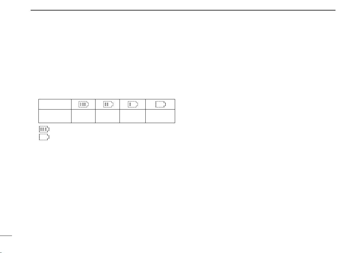
PANEL DESCRIPTION
Indication
Full Middle
Charging
required
No batteryBattery level
blinks when the battery is exhausted.
blinks when the battery is over charged.
2
y BELL INDICATOR
Appears/blinks when the matched signal is received,
according to the pre-programming.
u CALL CODE MEMORY INDICATOR
Appears when the call code memory is selected.
i BATTERY INDICATOR
Appears or blinks when the battery power decreases to a
specified level.
o ALPHANUMERIC DISPLAY
➥ Displays an operating channel number, channel name,
Set mode contents, DTMF code, etc.
➥ The indication mode can be selected from 1 line or 2
lines. Ask your dealer for details.
• In this instruction manual, the LCD illustration is described
using the 2 lines indication mode.
!0 KEY INDICATOR
Indicate the programmed function of the front panel keys
([P0], [P1], [P2] and [P3]).
5
■ Programmable function keys
The following functions can be assigned to [EMR], [Side1],
[Side2], [Side3], [P0], [P1], [P2] and [P3] programmable
function keys.
Consult your Icom dealer or system operator for details
concerning your transceivers programming.
If the programmable function names are bracketed in the
following explanations, the specific key is used to activate the
function depends on the programming.
CH UP AND DOWN KEYS “UP” “DOWN”
➥ Push to select an operating channel. When [Rotary
selector] selects “operating channel,” this key is not
available.
➥ Push to select a transmit code channel after pushing
[TX Code CH Select].
➥ Push to select a DTMF channel after pushing [DTMF
Autodial].
➥ Push to select a scan group after pushing and holding
[Scan].
➥ Push to select the desired application type, individual/
talkgroup ID, TX status message and SDM (Shor t Data
Message) after pushing [Digital Button].

PANEL DESCRIPTION
2
1
ZONE KEY “ZONE”
Push this key, then push [CH Up] or [CH Down] to select
the desired zone. When [Rotary selector] selects “operating
zone,” this key operation is not available.
What is “zone”?— Selected channels are assigned to a
zone according to how they are to be used in a group. For
example, ‘Staff A’ and ‘Staff B’ are assigned into a
“Business” zone, and ‘John’ and ‘Cindy’ are assigned into a
“Private” zone.
ZONE UP AND DOWN KEYS “ZNUP” “ZNDN”
Push to select an operating zone. When [Rotary selector]
selects “operating zone,” this key is not available.
SCAN KEY “SCAN”
➥ Push to start and cancel scanning operation.
• When Power ON Scan function is activated, push to pause the
scanning operation. And the paused scan restarts after the
specified time period has passed.
➥ Push and hold this key for 1 sec. to indicate the scan list,
then push [CH Up] or [CH Down] to select the desired list.
SCAN ADD/DEL (TAG) KEY “SCAD”
➥ Push to add the channel to, or delete it from, the current
scanning list.
➥ Push and hold for 1 sec. to display the scan list. Then push
[CH Up] or [CH Down] to select the desired scan list to
add or delete the channel. To exit the scan list selection
mode, push and hold this key again for 1 sec.
➥ When a signal is detected, and the scan pauses on a
channel, other than a primary or secondary channel, push
this key to clear the channel from the scan list.
Depending on the setting, the cleared channel is added
to the scan group again after the scan is cancelled.
(Nuisance Delete function)
MEMORY CH 1/2/3/4 KEYS “CH1” “CH2” “CH3” “CH4”
Push to select the memory channels 1 to 4 directly.
2
3
4
5
6
7
8
9
10
11
12
13
14
15
16
6

PANEL DESCRIPTION
2
MONI KEY “MON”
➥ Push to mute and release the CTCSS (DTCS) or 2-tone
squelch mute. Open any squelch/deactivate any mute
while pushing and holding this key. (LMR operation only)
➥ Activates one of (or two of) the following functions on each
channel independently: (PMR operation only)
• Push and hold to un-mute the channel (audio is emitted; ‘Audible’
condition).
• Push to mute the channel (sets to ‘Inaudible’ only).
• Push after the communication is nished to send a ‘reset code’.
(5-tone/BIIS operation only)
NOTE: The un-mute condition (‘Audible’ condition) may
automatically return to the mute condition (‘Inaudible‘
condition) after a specified period.
LIGHT KEY “LIGT”
Push to turn the transceiver’s backlight ON temporarily only
when the backlight function is turned OFF in user set mode.
LOCK KEY “LOCK”
➥ Push and hold for 1 sec. to electronically lock all
programmable keys for preventing accidental frequency
changes and unnecessary function access except the
following:
[PTT], [Call] (incl. Call A and Call B), [Moni(Audi)],
[Light], [Emergency], [Surveillance], [Lone Worker] and
[OPT 1/2/3].
➥ Push and hold for 1 sec. again to turn the lock function
OFF.
LONE WORKER KEY “LONE”
Push to turn the Lone Worker function ON or OFF.
• If the Lone Worker function is activated, the Emergency function is
automatically turned ON after the specified time period has passed
with no operation is performed.
HIGH/LOW KEY “H/L”
Push to select the transmit output power temporarily or
permanently, depending on the pre-setting.
• Ask your dealer for the output power level for each selection.
TONE/RAN CH SELECT KEY “T SEL”
➥ While in analog mode operation, push to enter the
continuous tone channel selection mode. Then select the
desired tone frequency/code setting with [CH Up] or [CH
Down]. After the selection, push this key again to set.
➥ While in digital mode operation, push to enter the RAN
channel selection mode. Then select the desired RAN
setting with [CH Up] or [CH Down]. After the selection,
push this key again to set.
➥ While in mixed (digital and analog) mode operation, push
to enter the continuous tone channel selection mode. Then
select the desired tone frequency/code setting with [CH
Up] or [CH Down]. After the selection, push this key to
set. After that, the RAN channel selection screen appears.
Select the desired RAN setting with [CH Up] or [CH Down].
After the selection, push this key again to set.
7
 Loading...