

Page 1
INSTRUCTION MANUAL
VHF TRANSCEIVERS
iF3100D
Series
UHF TRANSCEIVERS
iF4100D
Series
This device complies with Part 15 of the FCC
Rules. Operation is subject to the condition that
this device does not cause harmful interference.
Limited functions only
Limited functions only
The photo shows
the VHF transceiver.
Page 2

FOREWORD
Thank you for choosing this Icom product. This product is designed
and built with Icom’s state of the art technology and craftsmanship. With proper care this product should provide you with years of
trouble-free operation.
IMPORTANT
READ ALL INSTRUCTIONS carefully and completely before
using the transceiver.
SAVE THIS INSTRUCTION MANUAL— This instruc-
tion manual contains important operating instructions for the
IC-F3101D/IC-F3103D/IC-F3106D/IC-F3108D VHF TRANSCEIVERS and the IC-F4101D/IC-F4103D/IC-F4106D/IC-F4108D UHF
TRANSCEIVERS.
Icom, Icom Inc. and the Icom logo are registered trademarks of Icom Incorporated
(Japan) in Japan, the United States, the United Kingdom, Germany, France,
Spain, Russia, Australia, New Zealand, and/or other countries.
i
Page 3

EXPLICIT DEFINITIONS
WORD DEFINITION
RDANGER!
RWARNING!
CAUTION
NOTE
Icom is not responsible for the destruction or damage to the
Icom transceiver, if the malfunction is because of:
• Force majeure, including, but not limited to, fires,
earthquakes, storms, floods, lightnings, or other natural
disasters, disturbances, riots, war, or radioactive
contamination.
• The use of Icom transceiver with any equipment that is not
manufactured or approved by Icom.
Personal death, serious injury or an
explosion may occur.
Personal injury, fire hazard or electric
shock may occur.
Equipment damage may occur.
If disregarded, inconvenience only. No risk
of personal injury, fire or electric shock.
ii
Page 4

PRECAUTIONS
R DANGER! NEVER short terminals of the battery pack.
Also, current may flow into nearby metal objects such as a key, so
be careful when placing the battery packs (or the transceiver) in
handbags, and so on.
Simply carrying with or placing near metal objects such as a key,
and so on may cause shorting. This may damage not only the
battery pack, but also the transceiver.
R DANGER! Use and charge only specified Icom battery packs
with Icom transceivers or Icom chargers. Only Icom battery packs
are tested and approved for use with Icom transceivers or charged
with Icom chargers. Using third-party or counterfeit battery packs
or chargers may cause smoke, fire, or cause the battery to burst.
R WARNING! NEVER hold the transceiver so that the antenna
is very close to, or touching exposed parts of the body, especially
the face or eyes, while transmitting. The transceiver will perform
best if the microphone is 5 to 10 cm (2 to 4 inches) away from the
lips and the transceiver is vertical.
R WARNING! NEVER operate the transceiver with a headset
or other audio accessories at high volume levels. The continuous
high volume operation may cause a ringing in your ears. If you
experience the ringing, reduce the volume level or discontinue use.
R WARNING! NEVER operate the transceiver while driving a
vehicle. Safe driving requires your full attention—anything less may
result in an accident.
CAUTION: MAKE SURE the flexible antenna, battery pack
and jack cover are securely attached to the transceiver, and that
the antenna and battery pack are dry before attachment. Exposing
the inside of the transceiver to dust or water will result in serious
damage to the transceiver.
iii
Page 5

DO NOT operate the transceiver near unshielded electrical
blasting caps or in an explosive atmosphere.
DO NOT push [PTT] when you do not actually intend to transmit.
DO NOT operate or place the transceiver in direct sunlight or in
areas with temperatures below –30°C (+22°F) or above +60°C
(+140°F).
DO NOT modify the transceiver. The specifications may change
and then not comply with the requirements of a corresponded
regulation. The transceiver warranty does not cover any problems
caused by unauthorized modification.
DO NOT use harsh solvents such as benzine or alcohol when
cleaning, as they will damage the transceiver surfaces.
BE CAREFUL! The transceiver will become hot when operating
it continuously for long periods of time.
KEEP the transceiver away from heavy rain, and never immerse
it in the water. The transceiver meets IP54* requirements for dustprotection and splash resistance. However, once the transceiver
has been dropped, dust-protection and splash resistance cannot
be guaranteed because of possible damage to the transceiver’s
case or the waterproof seal.
* Only when the battery pack/case and jack cover are attached.
Even when the transceiver power is OFF, a slight current still
flows in the circuits. Remove the battery pack or batteries from
the transceiver when not using it for a long time. Otherwise, the
installed battery pack or batteries will become exhausted, and will
need to be recharged or replaced.
MAKE SURE to turn OFF the transceiver before connecting or
disconnecting the supplied or optional accessory.
iv
Page 6

FCC INFORMATION
• FOR CLASS B UNINTENTIONAL RADIATORS:
This equipment has been tested and found to comply with the limits
for a Class B digital device, pursuant to part 15 of the FCC Rules.
These limits are designed to provide reasonable protection against
harmful interference in a residential installation. This equipment
generates, uses and can radiate radio frequency energy and, if
not installed and used in accordance with the instructions, may
cause harmful interference to radio communications. However,
there is no guarantee that interference will not occur in a particular
installation. If this equipment does cause harmful interference to
radio or television reception, which can be determined by turning
the equipment off and on, the user is encouraged to try to correct
the interference by one or more of the following measures:
• Reorient or relocate the receiving antenna.
• Increase the separation between the equipment and receiver.
• Connect the equipment into an outlet on a circuit different from
that to which the receiver is connected.
• Consult the dealer or an experienced radio/TV technician for
help.
CAUTION: Changes or modifications to this device, not expressly
approved by Icom Inc., could void your authority to operate this
transceiver under FCC regulations.
v
Page 7
VOICE CODING TECHNOLOGY
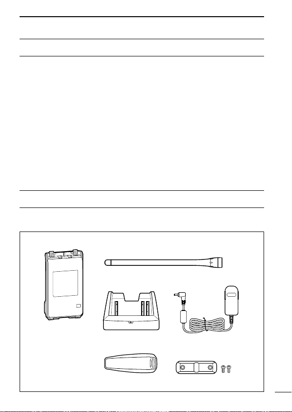
Flexible antenna
(This illustration is for the VHF type.)
Battery pack*
Belt clip*
Jack cover
(with screws)
Battery charger* Power adapter*
* Not supplied, or the shape is different, depending on the version.
The AMBE+2™ voice coding Technology embodied in this product
is protected by intellectual property rights including patent rights,
copyrights and trade secrets of Digital Voice Systems, Inc. This
voice coding Technology is licensed solely for use within this
Communications Equipment. The user of this Technology is explicitly
prohibited from attempting to extract, remove, decompile, reverse
engineer, or disassemble the Object Code, or in any other way convert
the Object Code into a human-readable form. U.S. Patent Nos.
#5,870,405, #5,826,222, #5,754,974, #5,701,390, #5,715,365,
#5,649,050, #5,630,011, #5,581,656, #5,517,511, #5,491,772,
#5,247,579, #5,226,084 and #5,195,166.
SUPPLIED ACCESSORIES
The following accessories are supplied with the transceiver.
vi
Page 8

TABLE OF CONTENTS
FOREWORD ........................................................................................ i
IMPORTANT ......................................................................................... i
EXPLICIT DEFINITIONS ..................................................................... ii
PRECAUTIONS ...................................................................................iii
FCC INFORMATION ........................................................................... v
VOICE CODING TECHNOLOGY ....................................................... vi
SUPPLIED ACCESSORIES ............................................................... vi
1 ACCESSORIES .........................................................................1–4
■ Accessory attachments .............................................................. 1
2 PANEL DESCRIPTION ............................................................ 5–11
■ Front, top and side panels ..........................................................5
■ LED indicator .............................................................................. 7
■ Programmable function keys ......................................................8
3 BASIC OPERATION ..............................................................12–24
■ Turning power ON ..................................................................... 12
■ Channel selection ..................................................................... 13
■ Call procedure .......................................................................... 14
■ Receiving and transmitting .......................................................15
■ Setting the microphone gain ..................................................... 18
■ Setting the squelch level ........................................................... 19
■ Setting the Beep level ............................................................... 20
■ Setting the Ringer level ............................................................. 21
■ Output power level selection .....................................................22
■ Priority A channel selection ...................................................... 22
■ MDC 1200 system operation .................................................... 23
■ Lone Worker Emergency Call ...................................................23
■ Emergency Call ........................................................................ 24
vii
Page 9

1
4 IDAS OPERATION ................................................................. 25–30
■ IDAS operation .........................................................................25
■ IDAS-Trunk operation ...............................................................25
■ Receiving a call.........................................................................26
■ Transmitting a call ..................................................................... 28
■ Position data transmission ........................................................ 30
■ Status message transmission ................................................... 30
■ Encryption function ................................................................... 30
5 BATTERY CHARGING ..........................................................31–41
■ Caution (for the BP-264
■ Caution (for the BP-265 Li-ion
■ Battery chargers ....................................................................... 36
6 BATTERY CASE ..........................................................................42
■ Optional battery case (BP-263) ................................................ 42
7 OPTIONS ............................................................................... 43–48
■ VOX function ............................................................................. 46
8 SAFETY TRAINING INFORMATION ..................................... 49–50
(INFORMATION EN MATIÈRE DE SÉCURITÉ) .................... 51–52
ni-mh battery)....................................31
battery) ...................................33
2
3
4
5
6
7
8
viii
Page 10
1
ACCESSORIES
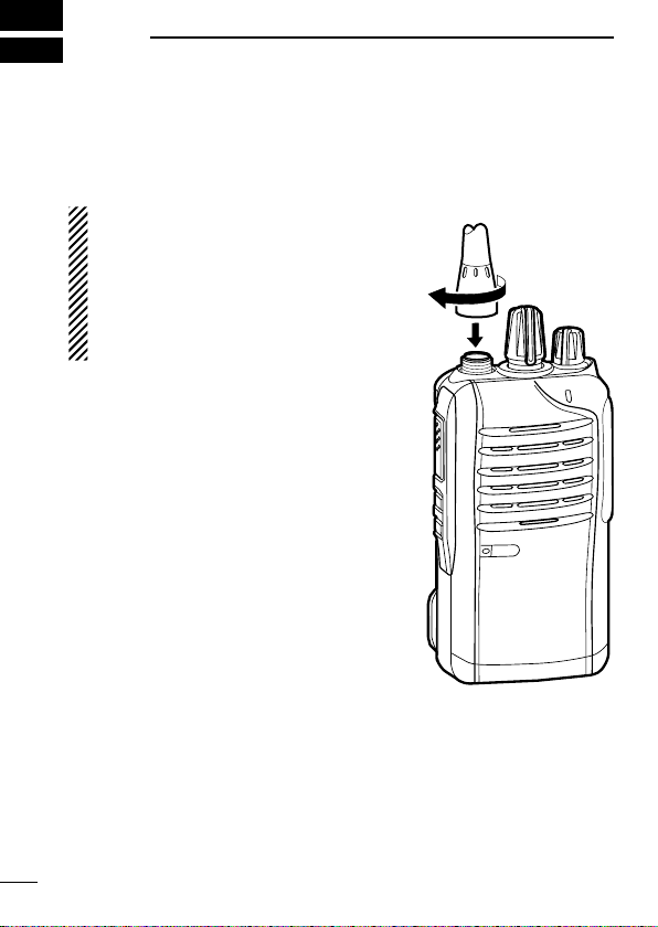
■ Accessory attachments
D Flexible antenna
Connect the flexible antenna to the antenna connector.
CAUTION:
• NEVER carry the transceiver by
holding the antenna.
• DO NOT connect the antenna
other than listed on page 44.
• Transmitting without an antenna
may damage the transceiver.
1
Page 11
ACCESSORIES
1
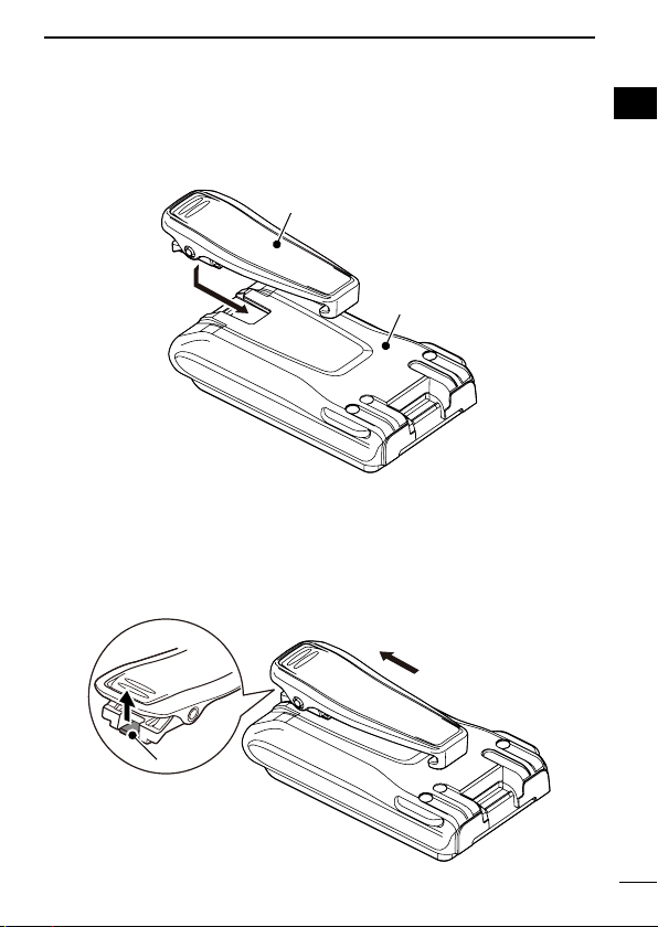
D Belt clip
To attach the belt clip:
➥ Slide the belt clip in the direction of the arrow until the belt clip
locks in place, and makes a ‘click’ sound.
Belt clip
Battery pack
To detach the belt clip:
q Remove the battery pack from the transceiver, if it is attached.
(p. 3)
w Lift the tab up (q), and slide the belt clip in the direction of the
arrow (w).
1
q
w
Ta b
2
Page 12
ACCESSORIES
k/case
q
1
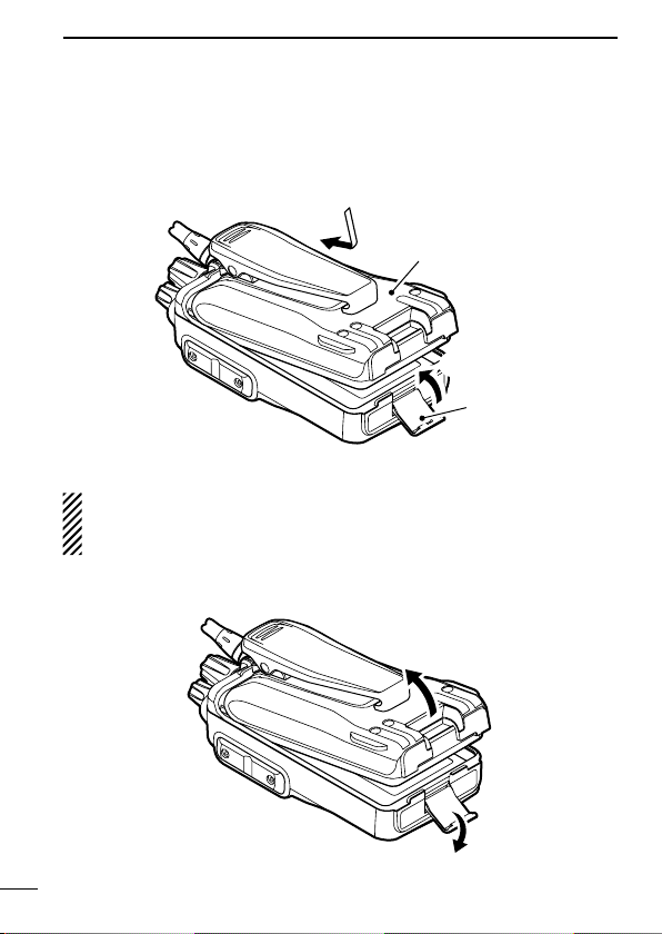
D Battery pack or case
To attach the battery pack or case:
q Fit the battery pack/case in the direction of the arrow, then close
it.
w Hook the latch until it makes a ‘click’ sound.
q
Battery pac
w
Latch
To remove the battery pack/case:
Be careful! The latch is tightly locked, so use caution when releasing it. DO NOT use your finger nail. Use the edge of a coin
or screwdriver tip to carefully release it
q Unhook the latch.
w Lift up the
battery pack/case
in the direction of the arrow.
.
w
3
Page 13
ACCESSORIES
1
NEVER remove or attach the
ceiver is wet or soiled. This may result in water or dust getting into
the tr
ansceiver,
damaged.
NOTE: Keep the battery terminals clean. It's a good idea to
occasionally clean them.
battery pack/case,
battery pack/case
and may result in them being
when the trans-
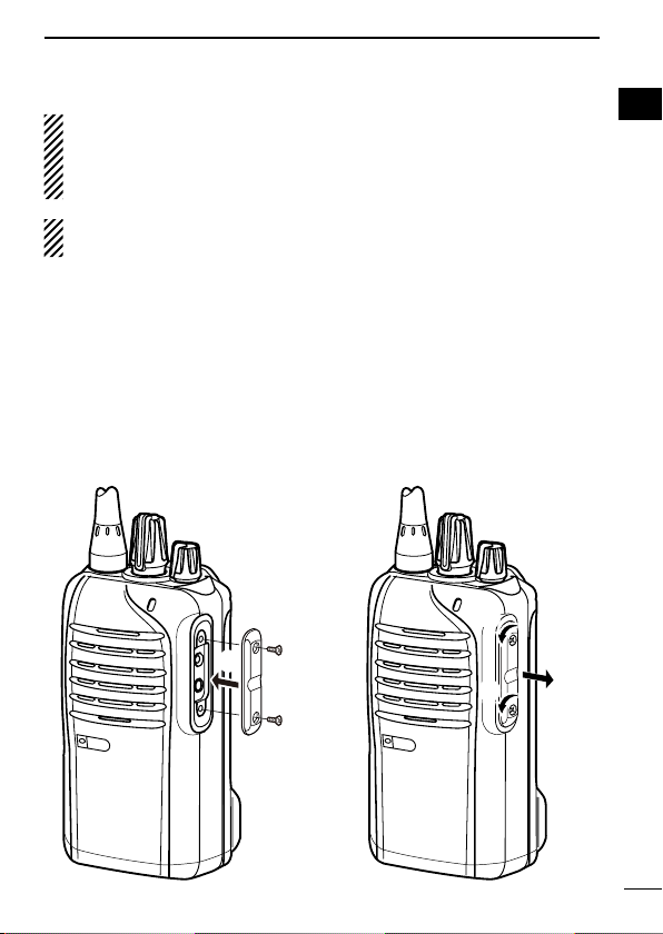
D Jack cover
Attach the jack cover when the optional equipment is not used.
To attach the jack cover:
q Attach the jack cover to the
[SP MIC] jack.
w Tighten the screws.
q
To detach the jack cover:
q Remove the screws with a
phillips screwdriver.
w Detach the jack cover to con-
nect the optional equipment.
w
w
q
q
1
w
4
Page 14
2
y
u
i
t
R
PANEL DESCRIPTION
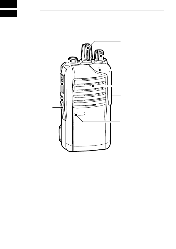
■ Front, top and side panels
q
ANTENNA
CONNECTOR
w
e
ROTARY
SELECTOR
VOLUME
CONTROL
LED INDICATO
PTT SWITCH
UPPER KEY
LOWER KEY
Speaker
r
Microphone
q ROTARY SELECTOR
Rotate to select the pre-programmed memory channels or scan
lists, depending on the pre-programming.
w VOLUME CONTROL [VOL]
Rotate to turn the power ON or OFF, and adjust the audio level.
5
SPEAKERMICROPHONE
JACK
Page 15
PANEL DESCRIPTION
2
e STATUS INDICATOR (p. 7)
➥ Lights red* while transmitting.
* When the optional battery case is attached, the LED indicator
lights orange.
➥ Lights green while receiving a signal, or when the squelch is
open.
➥ Lights/blinks orange when the matched 2/5-Tone code is re-
ceived, depending on the pre-programming.
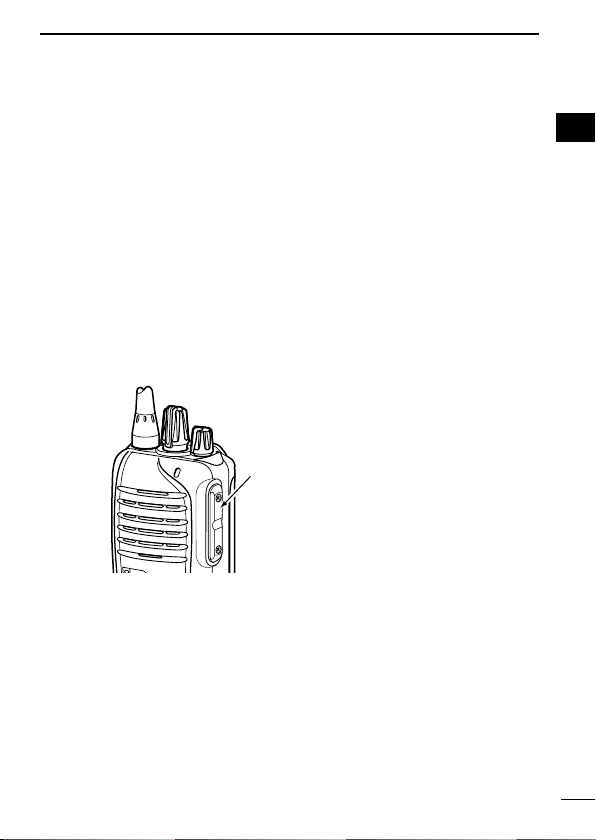
r SPEAKER-MICROPHONE JACK [SP MIC]
Connect the optional speaker-microphone or VOX adapter
cable.
Jack cover
NOTE: Attach the jack cover
when the optional equipment
is not used. (p. 4)
t LOWER KEY [Lower]
y UPPER KEY [Upper]
The desired function can be assigned by your dealer. (p. 8)
u PTT SWITCH [PTT]
Hold down to transmit; release to receive.
2
i ANTENNA CONNECTOR
Connect the antenna.
6
Page 16
PANEL DESCRIPTION
2
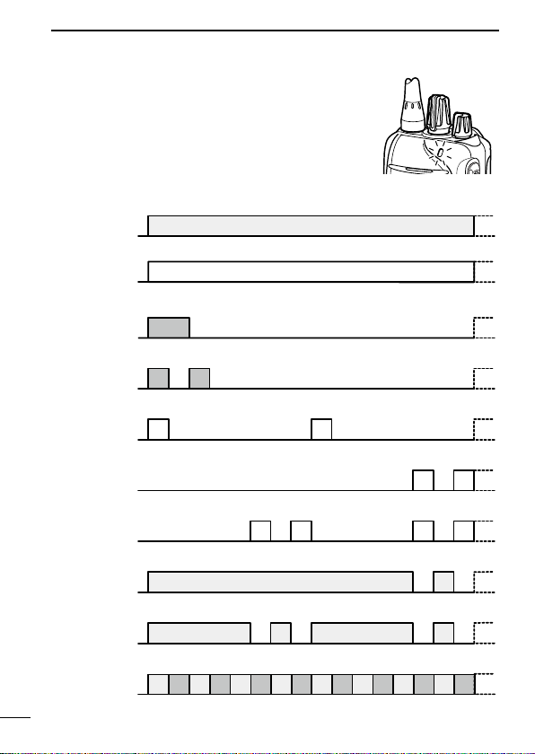
■ LED indicator
The LED indicator indicates the status of various
parameters of the transceiver as follows;
(Ref.; R=Red, G=Green, O=Orange)
• TX: Lights Red while transmitting a signal.
R*
• RX: Lights Green while receiving a signal.
G
• Call LED (ON): Turns ON while receiving a matched 2/5-Tone.
O
• Call LED (Blink): Blinks while receiving a matched 2/5-Tone.
O O
• Fast/Slow scan: Blinks when the Fast/Slow scan is activated.
G G
• Low Battery 1: You should charge the battery. (blinks slowly)
G G
• Low Battery 2: You must charge the battery. (blinks fast)
G G G G
• TX low Battery 1: Low Battery was detected during TX mode.
R* R*
• TX low Battery 2: Very Low Battery was detected during TX mode.
R* R* R* R*
• Channel Error: A non-programmed channel is selected.
R O R O R O R O R O R O R O R O
* Lights (or blinks) orange when the optional battery case is attached.
7
Page 17

PANEL DESCRIPTION
2
■ Programmable function keys
The following functions can be assigned to the [Upper] and [Lower]
programmable function keys.
Consult your Icom dealer or system operator for details concerning
your transceiver’s programming.
SCAN
Push to start and cancel the scanning operation.
• When the scan started with the Power ON Scan or Auto Scan function, push to pause the scanning operation. The paused scan resumes after the specified time period has passed.
PRIORITY A CHANNEL, PRIORITY B CHANNEL
Push to select the Priority A or Priority B channel.
PRIORITY A CHANNEL (REWRITE),
PRIORITY B CHANNEL (REWRITE)
➥ Push to select the Priority A or Priority B channel.
➥ Hold down [Prio A (Rewrite)] or [Prio B (Rewrite)] for 1 second to
assign the operating channel to Priority A or Priority B channel,
respectively.
MEMORY CHANNELS 1, 2, 3, 4
Push to directly select memory channel 1, 2, 3 or 4, if programmed.
Consult your dealer for details.
2
LONE WORKER (p. 23)
➥ Push to turn the Lone Worker function OFF.
➥ Hold down to turn the Lone Worker function ON.
• When the Lone Worker function is turned ON, and no operation is
performed for the specified time period, the Emergency function is
automatically turned ON.
8
Page 18

PANEL DESCRIPTION
2
MONITOR, MONITOR (AUDIBLE)
➥ Push to turn the CTCSS (DTCS) or 2/5-Tone squelch Mute ON
or OFF.
• Only during LMR operation, push to open any squelch functions, or deactivate any mute functions.
• Only during PMR operation, push to activate one or two of the
following functions* on each channel.
- Hold down to un-mute the channel (Audible mode).
- Push to mute the channel (Inaudible mode).
- Push to send a ‘reset code’ after the communication is finished.
*Ask your dealer for details.
NOTE: The un-mute condition may automatically return to
the mute condition, after a specified time period.
Depending on the presetting, holding down this key for 1 sec-
➥
ond cancels a scan.
LOCK
Hold down to electronically lock all programmable keys except
[Moni(Audi)], [Call] (including Call A and Call B), [Emergency],
Surveillance] and [Lone Worker].
HIGH/LOW (p. 22)
Select the transmit output power level temporarily or permanently,
depending on the presetting.
• Ask your dealer for the output power level for each selection.
TALK AROUND
➥ Push to turn the Talk Around function OFF.
➥ Hold down to turn the Talk Around function ON.
• The Talk Around function equalizes the transmit frequency to the
receive frequency for transceiver-to-transceiver communication.
DTMF AUTODIAL
Push to transmit a programmed DTMF code.
9
Page 19

PANEL DESCRIPTION
2
WIDE/NARROW
➥ Push to switch the IF bandwidth to Wide.
• The wide passband width can be selected from 20 or 25 kHz using
the optional cloning software (PMR operation only). Ask your dealer
for details.
➥ Hold down to switch the IF bandwidth to Narrow.
CALL, CALL A, CALL B
Push to transmit a 2/5-Tone code.
• Tone call transmission may be necessary before you call another sta-
tion, depending on your signalling system.
• [Call A] and/or [Call B] keys may be available when your system em-
ploys selective ‘Individual/Group’ calls. Ask your dealer which call is
assigned to each key.
EMERGENCY
Hold down for specified time period to transmit an emergency call.
• The emergency call transmits with beeps, and the LED lights red.
• The transceiver can transmit an emergency call without the beep
sounding and the LED indicator lighting. Ask your dealer for details.
• If you want to cancel the emergency call, hold down the key again
before transmitting the call.
• The emergency call is transmitted one time only, or repeatedly until re-
ceiving an acknowledgement signal, or until the power is turned OFF.
When a matched 5-Tone code signal is received, the emergency func-
tion can be cancelled depending on the presetting. (PMR operation
only)
2
SURVEILLANCE
➥ Push to turn the Surveillance function OFF.
➥ Hold down to turn the Surveillance function ON.
• When this function is turned ON, the beep is not heard and the LED
does not light when a signal is received, or a key is pushed.
10
Page 20

PANEL DESCRIPTION
2
SIREN
Hold down for 1 second to emit a siren sound.
This function can be used for situations other than an emergency
alert, such as a security alarm for example.
The transceiver emits the siren sound until the power is turned
OFF.
ENCRYPTION
Push to turn the Voice Encryption function ON or OFF while operating in the digital mode.
ANNOUNCE
Push to turn the Channel Announce function ON or OFF.
• When this function is turned ON, the transceiver announces the position of [ROTARY SELECTOR] between 1 and 16 when rotating [ROTARY SELECTOR] to a desired scale.
11
Page 21

BASIC OPERATION
[VOL]
[PTT]
[ROTARY SELECTOR]
■ Turning power ON
Prior to using the transceiver for the first
time, the battery pack must be fully charged
for optimum life and operation. (p. 31)
➥ Rotate [VOL] to turn power ON.
D Battery type selection
The battery type must be selected according to the battery pack or
case when it is changed, but only the first time it is used.
Check the battery type before you begin the selection procedure.
One to three beep(s) sound in sequence, so you must repeat the
steps until the number of beeps matches your battery type.
For example, if your battery type is a Li-ion battery pack, you must
repeat the procedure until one beep is heard.
q Set
[ROTARY SELECTOR] to any
channel other than Channel 16.
w Rotate [VOL] to turn OFF the trans-
ceiver’s power.
e
While holding down [PTT], rotate
[VOL] to turn ON the power.
• You should hold [PTT] until the battery type confirmation beeps sound.
(It takes approximately 5 seconds;
while holding down [PTT], the count
down beeps sound. After that, the confirmation beeps sound.)
• One beep sounds when the Li-ion battery is selected.
• Two beeps sound when the battery case is selected.
• Three beeps sound when the Ni-MH battery is selected.
r After the beep sounds, release [PTT].
t Repeat steps w to r until you select the attached battery type.
NOTE: This operation may not be available, depending on the
presetting. Ask your dealer for details.
3
2
3
[VOL]
12
Page 22

BASIC OPERATION
3
■ Channel selection
Several types of channel selecting methods are available. They
may differ, according to your system set up.
To select a desired operating channel, do one of the following.
• Rotate [ROTARY SELECTOR].
• Push one of memory channel keys, [MR-CH 1] to [MR-CH 4].
• Push one of these keys, [Prio A], [Prio B], [Prio A (Rewrite)] and
[Prio B (Rewrite)].
AUTOMATIC SCAN TYPE:
Selecting a channel is not necessary for this type. When turning ON
the power, the transceiver automatically starts scanning. Scanning
stops when a call is received.
NOTE: If the Move to Priority A channel at Power ON function
(p. 22) is turned ON, the transceiver does not start scanning at
power ON.
13
Page 23

BASIC OPERATION
Selective calling
Non-selective calling
3
■ Call procedure
When your system employs tone signalling (excluding CTCSS and
DTCS), the tone call procedure may be necessary prior to voice
transmission. The tone signalling that is employed in the transceiver
may be a selective calling system, which allows you to call only
specific station(s), and prevent unwanted stations from contacting
you.
q Select a desired TX code channel or 2/5-Tone code, according
to your System Operator’s instructions.
• This may not be necessary, depending on programming.
w Push [Call] (assigned to one of the dealer programmable keys.)
(p. 10)
e After transmitting a 2/5-Tone code, the remainder of your com-
munication can be carried out normally.
3
14
Page 24

BASIC OPERATION
3
■ Receiving and transmitting
CAUTION: Transmitting without an antenna will damage the
transceiver. See page 1 for antenna attachment.
Receiving:
q Rotate [VOL] to turn ON the power.
w Rotate [ROTARY SELECTOR], or push one of the memory
channel keys, [MR-CH 1] to [MR-CH 4], to select a channel.
e When receiving a call, adjust the audio output to a comfortable
listening level.
NOTE: When a matched RX code signal is received, audio from
the microphone is automatically transmitted for a specified time
period.*
* Depending on the presetting. Ask your dealer for details.
Transmitting:
Wait for the channel to become clear to avoid interference.
q While holding down [PTT], speak into the microphone at a
normal voice level.
w Release [PTT] to return to receive.
IMPORTANT: To maximize the readability of your signal;
1. Pause briefly after pushing [PTT].
2.
Hold the microphone 5 to 10 cm (2 to 4 inches) from your
mouth, then speak into the microphone at a normal voice level.
15
Page 25

BASIC OPERATION
3
D Transmitting notes
• Transmit inhibit function
The transceiver has several inhibit functions, which restrict transmission under the following conditions:
- The channel is muted.
- The channel is busy.
- A signal with the un-matched (or matched) CTCSS (or DTCS) tone
is received.
- The selected channel is a ‘receive only’ channel.
• Time-out timer
After continuously transmitting longer than the pre-programmed time
period, the time-out timer activates, and stops further transmitting.
• Penalty timer
Once the time-out timer activates, transmitting is further inhibited for
a time period determined by the penalty timer.
• PTTID call
The transceiver automatically sends the ID code (5-Tone, DTMF,
BIIS, MDC system or IDAS operations) when [PTT] is pushed (beginning of the transmission) and/or released (end of transmission),
depending on the presetting.
(PMR operation only)
3
16
Page 26

BASIC OPERATION
3
D DTMF transmission
If the transceiver has [DTMF Autodial] assigned to it, the automatic
DTMF transmission function is usable.
➥ Push [DTMF Autodial] to transmit the DTMF code.
D Receiving a Stun, Kill and Revive command
The dispatcher can send a 2/5-Tone signal that will stun, kill or revive your transceiver.
When the Stun command is received, a beep sounds*, and the
transceiver becomes unusable. Receiving a Revive command is
necessary to operate the transceiver again in this case.
When the Kill command is received, a beep sounds*, and the transceiver becomes unusable (the transceiver switches to the cloning
required condition). Cloning the transceiver is necessary to operate
the transceiver again in this case.
* Depending on the presetting. Ask your dealer for details.
17
Page 27

BASIC OPERATION
[Upper]
[ROTARY SELECTOR]
3
■ Setting the microphone gain
Adjusts the microphone gain.
q Rotate [VOL] to turn the trans-
ceiver power OFF.
w Set [ROTARY SELECTOR] to
Channel 16.
e While holding down [Upper],
rotate [VOL] to turn ON the
transceiver and enter the microphone gain adjustment mode.
r Push [Upper] to increase, or
push [Lower] to decrease the
microphone gain.
• The adjustable range is 1 (minimum) to 4 (maximum).
• A beep sounds after pushing
[Upper] or [Lower].
An error beep sounds if you try
to decrease more than 1 or try
to increase more than 4.
Therefore, you can determine the current level setting by the type
of beep that sounds.
t Rotate [VOL] to turn OFF the transceiver, then ON again to exit
the microphone gain adjustment mode.
[VOL]
3
NOTE:
• This operation may not be available, depending on the
presetting. Ask your dealer for details.
• When using the VOX function, we recommend setting the
microphone gain to 3. However, you can adjust it to suit your
operating environment (including your headset performance).
18
Page 28

BASIC OPERATION
[Upper]
[ROTARY SELECTOR]
3
■ Setting the squelch level
The squelch circuit mutes the received audio signal, depending on
the signal strength.
q Rotate [VOL] to turn the trans-
ceiver power OFF.
w Set [ROTARY SELECTOR] to
any channel other than Channel 16.
e While holding down [Upper], ro-
tate [VOL] to turn ON the power
and enter the squelch level adjustment mode.
r Push [Upper] to increase the
squelch level (tight squelch), or
push [Lower] to decrease the
squelch level (loose squelch).
• The adjustable range is 0 (loose
squelch) to 9 (tight squelch).
• A beep sounds after pushing
[Upper] or [Lower].
An error beep sounds if you try to decrease more than 0 or try to
increase more than 9.
Therefore, you can determine the current level setting by the type
of beep that sounds.
t Rotate [VOL] to turn the power OFF, then ON again to exit the
squelch level adjustment mode.
[VOL]
19
NOTE: This operation may not be available, depending on the
presetting. Ask your dealer for details.
Page 29

BASIC OPERATION
[Lo
[ROTARY SELECTOR]
■ Setting the Beep level
The beep function can be turned ON or OFF, and its level can be
adjusted between 1 and 5, or 1 (linked) and 5 (linked). When a
Linked option is selected, the beep level is adjustable with [VOL].
q Rotate [VOL] to turn the trans-
ceiver power OFF.
w Set [ROTARY SELECTOR] to
any channel other than Channel 16.
e While holding down [Lower], ro-
tate [VOL] to turn ON the power
and enter the beep level adjustment mode.
r
Push [Upper] to change the beep
level, or push [Lower] to turn the
beep function ON or OFF.
• The adjustable range is 1 to 5 or
1 (Linked) to 5 (Linked).
• If the level is set on 1 to 4 or 1
(Linked) to 4 (Linked), pushing
[Upper] increases the level.
If the level is 5 or 5 (Linked), 1 (Linked) or 1 is selected after push-
ing [Upper], respectively.
• A beep sounds after pushing [Upper]. Therefore, you can deter-
mine the current level setting by the type of beep that sounds.
• One beep sounds when the beep function is turned ON after push-
ing [Lower].
t Rotate [VOL] to turn OFF the transceiver, then ON again to exit
the beep level adjustment mode.
wer]
3
3
[VOL]
NOTE: This operation may not be available, depending on the
presetting. Ask your dealer for details.
20
Page 30

BASIC OPERATION
[Lo
[ROTARY SELECTOR]
3
■ Setting the Ringer level
The Ringer level can be adjusted between 1 and 5, or 1 (Linked)
and 5 (Linked). When a Linked option is selected, the Ringer level
is adjustable with [VOL].
q Rotate [VOL] to turn the trans-
ceiver power OFF.
w Set [ROTARY SELECTOR] to
Channel 16.
e While holding down [Lower], ro-
tate [VOL] to turn ON the power
and enter the Ringer level adjustment mode.
r Push [Upper] to increase, or
push [Lower] to decrease the
Ringer level.
• The adjustable range is 1 to 5 or
1 (Linked) to 5 (Linked).
• If the level is set on 5 or 5
(Linked), pushing [Upper] selects
1 (Linked) or 1, respectively. If the
level is 1 or 1 (Linked), pushing
[Lower] selects 5 (Linked) or 5,
respectively.
• A beep sounds after pushing [Upper] or [Lower]. Therefore, you
can determine the current level setting by the type of beep that
sounds.
t Rotate [VOL] to turn the power OFF, then ON again to exit the
beep level adjustment mode.
NOTE: This operation may not be available, depending on the
presetting. Ask your dealer for details.
wer]
[VOL]
21
Page 31

BASIC OPERATION
3
■ Output power level selection
If the transceiver has [High/Low] assigned to it, the transmit output
power level can be selected, depending on the presetting.
When the battery case is selected as the battery type, or the battery voltage drops to a low power level and the LED indicator status is “Low Battery 2,” the output power automatically switches to
“Low 1.” (pp. 7, 12)
➥ Push [High/Low] to select the transmit output power level.
• One beep sounds when “Low 1” is selected.
• Two beeps sound when “Low 2” is selected.
• Three beeps sound when “High” is selected.
■ Priority A channel selection
When one of the following operations is performed, the transceiver
automatically selects the Priority A channel.
• Turning the power ON
The Priority A channel is selected each time the transceiver power is turned ON.
• Auto reset
The Priority A channel is selected when the Auto Reset timer
ends.
3
22
Page 32

BASIC OPERATION
3
■ MDC 1200 system operation
The MDC 1200 signaling system enhances your transceiver’s capabilities. It allows PTT ID* and Emergency signaling.
* When [PTT] is pushed and/or released, the transceiver transmits your
station ID.
D Transmitting an Emergency Call
The MDC 1200 system’s Emergency feature can be accessed
using the [Emergency] key. The transceiver will send an Emergency
MDC 1200 system command once, or repeatedly for a programmed
number of times until it receives an acknowledgement signal.
The emergency call can be transmitted without a beep sound, depending on how the emergency function is programmed. Ask your
dealer for details.
■ Lone Worker Emergency Call
When the Lone Worker function is turned ON, and no operation is
performed for the specified time period*, the transceiver enters the
emergency mode, and then the countdown for the emergency call
transmission starts.
After the specified time period* has passed, an emergency call is
automatically transmitted once, or repeatedly*.
If someone operates the transceiver before the call is transmitted, the
transceiver exits the emergency mode, and the emergency call is can
celled.
* Depending on the presetting. Ask your dealer for details.
-
q Hold down [Lone Worker] to turn ON the Lone Worker function.
w Push [Lone Worker] to turn OFF the Lone Worker function.
23
Page 33

BASIC OPERATION
3
■ Emergency Call
When [Emergency] is held down for the specified time period*, the
emergency signal is transmitted once, or repeatedly, on the specified emergency channel.
A repeat emergency signal is automatically transmitted until you
turn the power OFF.
Depending on the pre-programmed settings, receiving a matching
5-Tone code cancels the transmission.
When no emergency channel is specified, the signal is transmitted
on the previously selected channel.
If you want to cancel the emergency call, hold down [Emergency]
again before transmitting the call.
If your transceiver is programmed for Silent operation, you can
transmit an Emergency call without the beep sounding and the LED
indicator lighting.
IMPORTANT: It is recommended to set an emergency channel
individually to provide the certain emergency call operation.
D NOTES
Depending on the presetting, the following functions are automatically activated. Ask your dealer for details.
• Auto TX function
After the emergency call transmission, audio from the microphone
is automatically transmitted for a specified time period.*
• Auto RX function
After the emergency call transmission, the transceiver stands by in
the audible mode for the specified time period.*
3
* Depending on the presetting. Ask your dealer for details.
24
Page 34

4
IDAS OPERATION
■ IDAS operation
The IC-F3100D series and IC-F4100D series provide Icom Digital
Advanced System (IDAS) that meets the 6.25 kHz emission mask
requirements for narrow banding, and increases efficiency of channel allocation and use of spectrum.
NOTE: During IDAS operation, BIIS 1200 and MDC 1200 system operations are not available.
■ IDAS-Trunk operation
The IDAS-Trunk system enables further effective channel management by sharing a minimum of channels with a large number of
users.
Rotate [ROTARY SELECTOR] to select the memory channel that is
programmed in the IDAS-Trunk zone.
NOTE: During IDAS-Trunk operation, you can receive and transmit digital calls in the same way with the following IDAS operation.
25
Page 35

IDAS OPERATION
4
■ Receiving a call
D Receiving a Call Alert
q When a Call Alert is received;
• The transceiver will automatically transmit the acknowledgement.
• The LED indicator blinks orange.
• Beeps sound.
w Hold down [PTT], then speak into the microphone.
e Release [PTT] to receive a response.
NOTE: The LED indicator or Beeps may differ, depending on the
presetting. Ask your dealer for details.
D Receiving a Stun, Kill or Revive
If an individual call with Stun or Kill command is received (RAN
code matching is not necessary depending on the presetting), the
transceiver will automatically transmit the acknowledgement, and
then you cannot receive* or transmit.
* Depending on the received Stun command setting.
➥ When a Stun command is received;
• The transceiver cannot be operated until the individual call with
Revive command is received (RAN code matching is not necessary depending on the presetting) or until the data cloning is
performed.
• Even if [ROTARY SELECTOR] is changed, the transceiver will
keep the same channel as the Stun command is received.
➥ When a Kill command is received;
• The LED indicator alternately blinks red and green.
• The transceiver cannot be operated until the data cloning is
performed. Ask your dealer for details.
NOTE: Depending on the presetting, the transceiver ignores the
Stun, Revive and Kill commands, which are from a non-specified
station.
4
26
Page 36

IDAS OPERATION
4
D Receiving a Remote Monitor or Radio Check Call
If an individual call with Remote monitor or Radio check command
is received (RAN code matching is not necessary depending on the
presetting), the transceiver will automatically transmit.
➥ When a Remote monitor command is received;
• The transceiver will automatically transmit the acknowledgement, and then it transmits the microphone audio for the set
time period.
➥ When a Radio check command is received;
• The transceiver will automatically transmit the acknowledgement.
27
Page 37

IDAS OPERATION
4
■ Transmitting a call
IDAS operation allows you to make a call to a specific station (Individual call) or to a particular group (Talkgroup call). Other digital
mode transceivers on the channel will not receive a call that does
not match their individual or talkgroup ID and/or RAN (Radio Access Number) code.
D Transmitting an Emergency Call
When [Emergency] is held down for the specified time period, the
emergency signal (digital command) is transmitted once or repeatedly* on the specified emergency channel. When no emergency channel is specified, the signal is transmitted on the operating channel.
* When the Repeat Cancel function is ON, the transceiver cancels
repeating after receiving an acknowledgement.
When the Repeat Cancel function is OFF, the transceiver repeats
calling according to the number of repeat cycles, even after receiving an acknowledgement.
Individual or Talkgroup call types of emergency calls can be prefixed. If the call type is not pre-fixed, the default or selected call
type is used.
If you want to cancel the emergency call, hold down [Emergency]
again before transmitting the call.
If your transceiver is programmed for Silent operation, you can
transmit an Emergency call without the beep sounding and the LED
indicator lighting.
4
The transceiver can also be programmed to keep the microphone
open during an emergency call, allowing monitoring of the situation.
Ask your dealer for details.
28
Page 38

IDAS OPERATION
4
IMPORTANT: It is recommended to set an emergency channel
individually to provide the certain emergency call operation.
NOTE: The Digital Request Ack function is activated, the transceiver transmits the emergency call with the request to send
back an acknowledgment.
29
Page 39

IDAS OPERATION
4
■ Position data transmission
When an optional HM-171GP or any other GPS receiver is connected to the transceiver, the position (longitude and latitude) data
can be transmitted automatically when;
• After sending a Status Call
- Set the ‘Send with Status Call’ item as ‘Enable.’
• After sending an Emergency Call
- Set the ‘Send with Emergency’ item as ‘Enable.’
• After sending a Voice Call
- Set the ‘Send with Voice Call’ item as ‘Enable.’
Ask your dealer or system operator for connection details.
■ Status message transmission
The status message can be transmitted automatically.
The status message is transmitted when the transceiver is turned
ON or OFF.
- Select a status message to be transmitted in ‘Power ON Status’
or ‘Power OFF Status’ item, respectively.
- Select a target station ID in ‘Power Status ID’.
■ Encryption function
The encryption function enables voice scrambling, which provides
private digital communication between stations.
4
Push [Encryption] to turn the encryption function ON or OFF.
30
Page 40

5
BATTERY CHARGING
■ Caution (for the BP-264 ni-mh battery)
R DANGER! KEEP battery packs away from fire. Fire or heat may
cause them to rupture or explode. Dispose of an used battery pack
according to local ordinances and/or regulations.
R DANGER! NEVER immerse the battery pack in water. If the
battery pack becomes wet, be sure to wipe it dry BEFORE attaching
it to the transceiver.
R WARNING! NEVER charge the transceiver during a lightning
storm. It may result in an electric shock, cause a fire or damage the
transceiver. Always disconnect the power adapter before a storm.
CAUTION: Always use the battery within the specified temperature
range, –5˚C to +60˚C (+23˚F to +140˚F). Using the battery out of its
specified temperature range will reduce the battery’s performance
and battery life.
CAUTION: Shorter battery life could occur if the battery is left
completely discharged, or in an excessive temperature environment
(above +55˚C: +131˚F) for an extended period of time. If the battery
must be left unused for a long time, it must be detached from the
transceiver after charging. Keep it safely in a cool dry place at the
following temperature range:
–20˚C to +45˚C (–4˚F to +113˚F) (within a month)
–20˚C to +35˚C (–4˚F to +95˚F) (within six months)
–20˚C to +25˚C (–4˚F to +77˚F) (within a year*)
* We recommend charging the battery pack every 6 months.
Clean the battery terminals to avoid rust or misscontact.
NOTE: Keep the battery terminals clean. It's a good idea to
occasionally clean them.
31
Page 41

BATTERY CHARGING
If your Ni-MH battery pack seems to have no capacity, even after
being charged, completely discharge it by leaving the power ON
overnight. Then, fully charge the battery pack again. If the battery
pack still does not retain a charge (or only very little charge), a new
battery pack must be purchased. (p. 43)
Prior to using the transceiver for the first time, the battery pack must
be fully charged for optimum life and operation.
• Recommended temperature range for charging:
+10°C to +40°C (+50˚F to +104˚F) (rapid charge: with BC-191)
0°C to +45°C (+32˚F to +113˚F) (regular charge: with BC-192)
• Use the supplied charger or optional charger (BC-191 for rapid
charging, BC-192 for regular charging) only. NEVER use other
manufacturers’ chargers
The battery pack contains a rechargable battery.
Charge the battery pack before first operating the transceiver, or
when the battery pack becomes exhausted.
If you want to prolong the battery life, the following points should be
observed:
• Avoid over charging. The charging time period by the BC-192
should be less than 48 hours.
• Use the battery pack until it becomes almost completely exhausted,
under normal conditions. We recommend battery charging after
transmitting becomes impossible.
.
5
5
32
Page 42

BATTERY CHARGING
5
■ Caution (for the BP-265 Li-ion battery)
Misuse of Li-ion batteries may result in the following hazards: smoke,
fire, or the battery may rupture. Misuse can also cause damage to
the battery or degradation of battery performance.
D Battery caution
R DANGER! DO NOT hammer or otherwise impact the battery. Do
not use the battery if it has been severely impacted or dropped, or if
the battery has been subjected to heavy pressure. Battery damage
may not be visible on the outside of the case. Even if the surface
of the battery does not show cracks or any other damage, the cells
inside the battery may rupture or catch fire.
R DANGER! NEVER use or leave battery packs in areas with
temperatures above +60˚C (+140˚F). High temperature buildup in the
battery, such as could occur near fires or stoves, inside a sun-heated
vehicle, or in direct sunlight for long periods of time may cause the
battery to rupture or catch fire. Excessive temperatures may also
degrade battery performance or shorten battery life.
R DANGER! DO NOT expose the battery to rain, snow, seawater,
or any other liquids. Do not charge or use a wet battery. If the battery
gets wet, be sure to wipe it dry before using. The battery is not
waterproof.
R DANGER! KEEP battery packs away from fire. Fire or heat may
cause them to rupture or explode. Dispose of an used battery pack
according to local ordinances and/or regulations.
R DANGER! NEVER solder the battery terminals or NEVER modify
the battery pack. This may generate heat in the battery, and the
battery pack may burst, emit smoke or catch fire.
R DANGER! Use the battery only with the transceiver for which it is
specified. Never use a battery with any other equipment, or for any
purpose that is not specified in this instruction manual.
33
Page 43

BATTERY CHARGING
R DANGER! If fluid from inside the battery gets in your eyes,
blindness can result. Rinse your eyes with clean water, without
rubbing them, and see a doctor immediately.
R
WARNING! Immediately stop using the battery if it emits an
abnormal odor, heats up, or is discolored or deformed. If any of these
conditions occur, contact your Icom dealer or distributor.
R
WARNING! Immediately wash, using clean water, any part of the
body that comes into contact with fluid from inside the battery.
R
WARNING! NEVER put the battery in a microwave oven, high-
pressure container, or in an induction heating cooker. This could
cause a fire, overheating, or cause the battery to rupture.
CAUTION: Always use the battery within the specified temperature
range, –20˚C to +60˚C (–4˚F to +140˚F). Using the battery out of its
specified temperature range will reduce the battery’s performance
and battery life.
CAUTION: Shorter battery life could occur if the battery is left fully
charged, completely discharged, or in an excessive temperature
environment (above +50˚C: +122˚F) for an extended period of time.
If the battery must be left unused for a long time, it must be detached
from the transceiver after discharging.
You may use the battery until the remaining capacity is about half,
then keep it safely in a cool dry place within the temperature range
as shown below:
–20˚C to +50˚C (–4˚F to +122˚F) (within a month)
–20˚C to +35˚C (–4˚F to +95˚F) (within three months)
–20˚C to +20˚C (–4˚F to +68˚F) (within a year)
5
5
34
Page 44

BATTERY CHARGING
5
BE SURE to replace the battery pack with a new one approximately
five years after manufacturing, even if it still holds a charge. The
inside battery material will become weak after a period of time, even
with little use. The estimated number of times you can charge the
battery is between 300 and 500.
Even when the battery appears to be fully charged, the operating
time of the transceiver may become short when:
• Approximately five years have passed since the battery was
manufactured.
• The battery has been repeatedly charged.
D Charging caution
R DANGER! NEVER charge the battery pack in areas with
extremely high temperatures, such as near fires or stoves, inside
a sun heated car, or in direct sunlight. In such environments, the
safety/protection circuit in the battery will activate, causing the
battery to stop charging.
R WARNING! NEVER charge the transceiver during a lightning
storm. It may result in an electric shock, cause a fire or damage
the transceiver. Always disconnect the power adapter before a
storm.
R
WARNING! DO NOT charge or leave the battery in the battery
charger beyond the specified time for charging. If the battery is not
completely charged by the specified time, stop charging and remove
the battery from the battery charger. Continuing to charge the battery
beyond the specified time limit may cause a fire, overheating, or the
battery may rupture.
R
WARNING! NEVER insert the transceiver (battery attached to the
transceiver) into the charger if it is wet or soiled. This could corrode
the battery charger terminals or damage the charger. The charger is
not waterproof.
CAUTION: DO NOT charge the battery outside of the specified
temperature range: BC-193 (+10˚C to +40˚C: +50˚F to +104˚F). Icom
recommends charging the battery at +20˚C (+68˚F). The battery may
heat up or rupture if charged out of the specified temperature range.
Additionally, battery performance or battery life may be reduced.
35
Page 45

BATTERY CHARGING
Po
(A
*
■ Battery chargers
D Using the BC-191 to rapid charge the BP-264
The BC-191 provides rapid charging of the Ni-MH battery pack
(BP-264 only). Never use for any other battery pack.
Charging time for the BP-264: Approximately 2 hours.
The following item is additionally required:
• A power adapter (not supplied with some versions) or the DC
power cable (OPC-515L/CP-23L).
Battery packTransceiver
Tu rn OFF the power
wer adapter
different type,
or no power
adapter is supplied, depending
on the version.)
Optional OPC-515L*
(for power source) or
CP-23L (for 12 V cigarette lighter socket)
can be used instead
of the power adapter.
About OPC-515L
White line:
:
Black line
CAUTION: NEVER connect the
OPC-515L to a power source
using reverse polarity.
This will ruin the battery charger.
Screws*
( Self tapping screw:
M3.5 × at least 30 mm)
*Purchase separately.
Using screws is recom-
mended to secure the
charger.
Status indicator
• Lights orange:
While charging.
• Lights green:
Charging is completed.
5
5
36
Page 46

BATTERY CHARGING
*
Battery packTransceiver
5
D Using the BC-192 to regular charge the BP-264
The BC-192 provides regular charging of the Ni-MH battery pack
(BP-264 only). Never use for any other battery pack.
Charging time for the BP-264 (with BC-147S): Approximately 16 hours.
The following item is additionally required:
• A power adapter (not supplied with some versions) or the DC
power cable (OPC-515L).
Tu rn OFF the power
Power adapter
(A different type, or
no power adapter
is supplied,
depending on the
version.)
Optional OPC-515L*
(for power source)
can be used instead
of the power adapter.
About OPC-515L
White line:
:
Black line
CAUTION: NEVER connect the
OPC-515L to a power source
using reverse polarity.
This will ruin the battery charger.
Charging time period differs
depending on the input voltage.
: Approx. 36 hours
12 V
: Approx. 21 hours
13.8 V
: Approx. 16 hours
16 V
37
Screws*
( Self tapping screw:
M3.5 × at least 30 mm)
*Purchase separately.
Using screws is recom-
mended to secure the
charger.
Status indicator
Lights green while charging.
NOTE:
The status indicator will not go
out even after a battery pack is
fully charged.
Page 47

BATTERY CHARGING
Po
(A diff
D Using the BC-193 to rapid charge the BP-265
The BC-193 provides rapid charging of the Li-ion battery pack
(BP-265 only). Never use for any other battery pack.
Charging time for the BP-265: Approximately 2.5 hours.
The following item is additionally required:
• A power adapter (not supplied with some versions) or the DC
power cable (OPC-515L/CP-23L).
Battery packTransceiver
Tu rn OFF the power
wer adapter
erent type, or
no power adapter is
supplied, depending
on the version.)
Optional OPC-515L*
(for power source) or
CP-23L (for 12 V cigarette lighter socket)
can be used instead
of the power adapter.
*
About OPC-515L
White line:
:
Black line
CAUTION: NEVER connect the
OPC-515L to a power source
using reverse polarity.
This will ruin the battery charger.
Screws*
( Self tapping screw:
M3.5 × at least 30 mm)
*Purchase separately.
Using screws is recom-
mended to secure the
charger.
Status indicator
• Lights orange:
While charging.
• Lights green:
Charging is completed.
5
5
38
Page 48

BATTERY CHARGING
5
D Using the BC-197 to rapid charge the BP-264 or
BP-265
The BC-197 rapidly charges up to six battery packs.
Charging time for the BP-264: Approximately 2 hours.
Charging time for the BP-265: Approximately 2.5 hours.
The following additional item is required:
• A power adapter (not supplied with some versions) or the DC
power cable (OPC-656)
Battery pack
Transceiver
Status indicator
(each indicator independently functions)
39
Tu rn OFF the power
Charger adapters* are
installed in each slot.
The shape of charger adapter depends
*
on the version of the BC-197.
Power adapter
(A power adapter is
not supplied with
some versions.)
DC power cable (OPC-656)
(Connect to a DC power supply:
12 to 16 V/at least 7 A)
Red line : + Black line : _
Page 49

BATTERY CHARGING
5
There are two types of BC-197 chargers for the IC-F3100D series
or IC-F4100D series; one is for Ni-MH batteries, and the other is for
Li-ion batteries.
Before you purchase a BC-197, check the type of battery you are
using, and then be sure to choose the suitable charger.
BC-197 Charger Type Chargeable Battery
With AD-120* charger adapters BP-264 Ni-MH battery
With AD-121* charger adapters BP-265 Li-ion battery
* The type of the charger adapter, AD-120 or AD-121 is printed on the
inside bottom of the charger adapter, and the type of battery it holds is
printed on the top right corner of the adapter.
5
40
Page 50

BATTERY CHARGING
5
IMPORTANT:
Ensure the tabs on the battery pack are correctly aligned with
the guide rails inside the charger.
Tabs
BC-191, BC-192, BC-193
Guide rail
41
Page 51

BATTERY CASE
6
■ Optional battery case (BP-263)
When using the optional battery case, install 6 × AA (LR6) size
alkaline batteries, as illustrated below.
q Remove the battery case, if it is attached. (pp. 3, 4)
w Install 6 × AA (LR6) size alkaline batteries.
• Install only alkaline batteries.
• Be sure to observe the correct polarity.
Be careful! The negative
terminals of the battery case
protrude from the body, so
pay attention not to injure
your fingers when inserting
the batteries.
e Attach the battery case. (pp. 3, 4)
CAUTION:
• When installing batteries, make sure they are all the same
brand, type and capacity. Also, do not mix new and old batteries together.
• Keep the battery terminals clean. It's a good idea to occasionally clean them.
• Never incinerate used battery cells since internal battery gas
may cause them to rupture.
• Never expose a detached battery case to water. If the battery
case gets wet, be sure to wipe it dry before using it.
• Never use batteries whose insulated cover is damaged.
NOTE: When the optional battery case is attached, the battery
type must be selected as “Battery case operation” when turning
the transceiver ON. Ask your dealer for details. (p. 12)
5
6
42
Page 52

7
OPTIONS
D BATTERY PACK
—*
1
2
Battery pack Voltage Capacity Battery life*
BP-263
BP-264 7.2 V 1400 mAh (typ.)
BP-265 7.4 V
1
*
When the power save function is turned ON, and the operating time
is calculated under the following conditions;
TX : RX : standby = 5 : 5 : 90
*2 The average operating time depends on the alkaline cells used.
Battery case for
AA (LR6) × 6 alkaline
1900 mAh (min.)
2000 mAh (typ.)
VHF 12 hrs.
UHF 11.3 hrs.
VHF 17.5 hrs.
UHF 16.1 hrs.
D BELT CLIPS
• MB-124 beLt cLip
Exclusive alligator-type belt clip.
D CHARGERS
• BC-191 desktop charger + BC-123S ac adapter
For rapid charging of the Ni-MH battery pack. A power adapter is
supplied with the charger, depending on the version.
Charging time for the BP-264: Approximately 2 hours.
• BC-192
For regular charging of the Ni-MH battery pack. A power adapter
is supplied with the charger, depending on the version.
Charging time for the BP-264: Approximately 16 hours.
• BC-193
For rapid charging of the Li-ion battery pack. A power adapter is
supplied with the charger, depending on the version.
Charging time for the BP-265: Approximately 2.5 hours.
desktop charger + BC-147S ac adapter
desktop charger + BC-123S ac adapter
43
Page 53

OPTIONS
7
• BC-197 muLti-charger
For rapid
power adapter may
the version.
simultaneously
charging of up to six battery packs. A
be supplied with the charger, depending on
There are two types of BC-197 chargers for the IC-
F3100D/IC-F4100D series.
BC-197 Charger Type Chargeable Battery Charging time
With AD-120* BP-264 Ni-MH battery Approx. 2 hrs.
With AD-121* BP-265 Li-ion battery Approx. 2.5 hrs.
* Either AD-120 or AD-121 charger adapters are installed in the BC-
197, depending on the chargeable battery pack.
D DC POWER CABLES
• CP-23L cigarette Lighter cabLe
Allows charging of the battery pack through a 12 V cigarette lighter
socket. (For BC-191/BC-193)
• OPC-515L/OPC-656
dc power cabLe
For charging of the battery packs using a 12 V DC power source
instead of the power adapter.
(OPC-515L for BC-191/BC-192/BC-193: OPC-656 for BC-197)
D ANTENNAS
• FA-SC73US/FA-SC56VS/FA-SC57VS stubby antennas
FA-SC73US : 450–490 MHz FA-SC56VS : 150–162 MHz
FA-SC57VS : 160–174 MHz
• FA-SC25U/FA-SC57U/FA-SC72U/
FA-SC25V/FA-SC55V
FA-SC25U : 400–430 MHz FA-SC57U : 430–470 MHz
FA-SC72U : 470–520 MHz FA-SC25V : 136–155 MHz
FA-SC55V : 146–174 MHz
• FA-SC61VC/FA-SC61UC
FA-SC61VC : 136–174 MHz FA-SC61UC : 380–520 MHz
antennas
cut antennas
7
44
Page 54

OPTIONS
7
D OTHER OPTIONS
• AD-98FSC antenna connector converter
Allows you to connect an external antenna with a BNC connector.
• HM-158L/HM-159L speaker-microphone
Combination speaker-microphone that provides convenient
operation while hanging the transceiver on your belt.
• HM-171GP
GPS speaker-microphone for BIIS and Digital modes operation.
• HS-94/HS-95/HS-97
HS-94 : Ear hook type
HS-95 : Neck-arm type
HS-97 : Throat microphone
OPC-2004 : Allows you to connect the HS-94/HS-95/HS-97 to
• SP-27
Provides clear audio in noisy environments.
Some options may not be available in some countries. Please ask your
dealer for details.
speaker-microphone
headset + OPC-2004 pLug adapter cabLe
the transceiver. After connection, the VOX function
can be used.
tube earphone
45
Page 55

OPTIONS
OPC-2004
7
■ VOX function
The transceiver has a VOX function, which allows you hands-free
operation.
An optional headset (HS-94/HS-95/HS-97) and a plug adapter
cable (OPC-2004) are additionally required for operation.
• The VOX (voice operated transmission) function starts transmitting
when you speak into the microphone, without needing to push the PTT
switch; then, automatically returns to receive when you stop speaking.
D Optional unit connection
q Rotate [VOL] to turn the transceiver power OFF.
w Remove the jack cover. (p. 4)
e Connect the optional headset (HS-94, HS-95 or HS-97) and
OPC-2004 as described below.
HS-94
[VOL]
w
e
q
7
46
Page 56

OPTIONS
[VOL]
[Upper]
[PTT]
[ROTARY SELECTOR]
7
D Turning the VOX function ON or OFF
The VOX function can be turned ON or OFF when turning the transceiver power ON.
q Rotate [VOL] to turn the trans-
ceiver power OFF.
w Set [ROTARY SELECTOR] to
any channel other than Channel 16.
e While holding down [PTT] and
[Upper], rotate [VOL] to turn ON
the power to switch the VOX
function ON or OFF.
• One beep sounds when the VOX
function is turned OFF.
• Two beeps sound when the VOX
function is turned ON.
NOTE: This operation may not be available, depending on the
presetting. Ask your dealer for details.
47
Page 57

OPTIONS
[Upper]
[PTT]
[ROTARY SELECTOR]
D Setting the VOX gain
The VOX sensitivity level can be adjusted from 1 (minimum) to 10
(maximum).
q
Connect the optional headset
(HS-94, HS-95 or HS-97)
OPC-2004. (p. 46)
w Rotate [VOL] to turn the trans-
ceiver power OFF.
e Set [ROTARY SELECTOR] to
Channel 16.
r While holding down [PTT] and
[Upper], rotate [VOL] to turn ON
the power and enter the VOX
gain adjustment mode.
t Push [Upper] to increase, or
push [Lower] to decrease the
VOX gain while speaking into
the optional headset.
• The adjustable range is 1 (minimum) to 10 (maximum).
• A beep sounds after pushing [Upper] or [Lower].
If the level is set on 1 or 10, an error beep sounds after pushing.
Therefore, you can determine the current level setting by the type
of beep that sounds.
y Rotate [VOL] to turn the power OFF, then ON to exit the VOX
gain adjustment mode.
NOTE:
• This operation may not be available, depending on the presetting. Ask your dealer for details.
• Set the microphone gain before setting the VOX gain. (p. 18)
and
7
[VOL]
7
48
Page 58

8
WARNING
This radio has been tested and complies with the FCC RF exposure
limits for “Occupational Use Only”. In addition, your Icom radio complies
with the following Standards and Guidelines with regard to RF energy
and electromagnetic energy levels and evaluation of such levels for exposure to humans:
• FCC OET Bulletin 65 Edition 97-01 Supplement C, Evaluating
• American National Standards Institute (C95.1-1992), IEEE Standard
• American National Standards Institute (C95.3-1992), IEEE Recom-
•
CAUTION
SAFETY TRAINING INFORMATION
Your Icom radio generates RF electromagnetic energy
during transmit mode. This radio is designed for and
classified as “Occupational Use Only”, meaning it must
be used only during the course of employment by individuals aware of the hazards, and the ways to minimize
such hazards. This radio is NOT intended for use by the
“General Population” in an uncontrolled environment.
Compliance with FCC Guidelines for Human Exposure to Radio
Frequency Electromagnetic Fields.
for Safety Levels with Respect to Human Exposure to Radio Frequency Electromagnetic Fields, 3 kHz to 300 GHz.
mended Practice for the Measurement of Potentially Hazardous
Electromagnetic Fields– RF and Microwave.
The accessories (antennas, batteries, belt clips, speaker-microphone, etc. that is listed on pages 43–45) are authorized for use
with this product. Use of accessories other than those specified may
result in RF exposure levels exceeding the FCC requirements for
wireless RF exposure.
To ensure that your expose to RF electromagnetic
energy is within the FCC allowable limits for occupational use, always adhere to the following guidelines:
49
Page 59

SAFETY TRAINING INFORMATION
• DO NOT operate the radio without a proper antenna attached, as
this may damaged the radio and may also cause you to exceed FCC
RF exposure limits. A proper antenna is the antenna supplied with
this radio by the manufacturer or antenna specifically authorized by
the manufacturer for use with this radio.
• DO NOT transmit for more than 50% of total radio use time (“50%
duty cycle”). “50% duty cycle” is also applicable to VOX/PTT mode.
Transmitting more than 50% of the time can cause FCC RF exposure compliance requirements to be exceeded. The radio is transmitting when the “LED indicator” lights red. You can cause the radio
to transmit by pressing the “PTT” switch or VOX function.
• ALWAYS keep the antenna at least 2.5 cm (1 inch) away from the
body when transmitting and only use the Icom belt-clip which is
listed on page 43 when attaching the radio to your belt, etc., to ensure FCC RF exposure compliance requirements are not exceeded.
To provide the recipients of your transmission the best sound quality, hold the antenna at least 5 cm (2 inches) from your mouth, and
slightly off to one side.
The information listed above provides the user with the information
needed to make him or her aware of RF exposure, and what to do to assure that this radio operates with the FCC RF exposure limits of this radio.
Electromagnetic Interference/Compatibility
During transmissions, your Icom radio generates RF energy that can
possibly cause interference with other devices or systems. To avoid such
interference, turn off the radio in areas where signs are posted to do so.
DO NOT operate the transmitter in areas that are sensitive to electromagnetic radiation such as hospitals, aircraft, and blasting sites.
8
8
Occupational/Controlled Use
The radio transmitter is used in situations in which persons are exposed as
consequence of their employment provided those persons are fully aware
of the potential for exposure and can exercise control over their exposure.
50
Page 60

INFORMATION EN MATIÈRE DE SÉCURITÉ
AVERTISSEMENT
MISE EN GARDE
8
Votre radio Icom produit une énergie électromagnétique de radiofréquences (RF), en mode de transmission. Cette radio est conçue pour un «usage
professionnel seulement» et classée comme tel, ce
qui signifie qu’elle doit être utilisée uniquement dans
le cadre d'un travail par des personnes conscientes
des dangers et des mesures visant à minimiser ces
dangers. Elle N’EST PAS conçue pour une «utilisation
Cet appareil a été évalué et jugé conforme, aux limites d’exposition aux
RF de la FCC, pour une «utilisation grand public». En outre, votre radio
Icom satisfait les normes et directives qui suivent en matière de niveaux
d'énergie et d
niveaux en ce qui concerne l
• Supplément C, édition 97-01, du Bulletin OET n° 65 de la FCC,
«Evaluating Compliance with FCC Guidelines for Human Exposure
to Radio Frequency Electromagnetic Fields».
• Norme de l’American National Standards Institute (ANSI): IEEE
C95.1-1992 sur les niveaux de sécurité compatibles avec l
humaine aux champs électromagnétiques de radiofréquences (3 kHz
à 300 GHz).
• Norme de l’ANSI: IEEE C95.3-1992 sur la méthode d’évaluation recommandée du champ magnétique potentiellement dangereux des
radiofréquences et des micro-ondes.
•
Les accessoires illustrés à la p. 43-45 sont approuvés pour une utilisation avec ce produit. L’utilisation d’accessoires autres que ceux précisés peut entraîner des niveaux d’exposition aux RF supérieures aux
limites établies par la FCC en matière d’exposition aux RF sans fil.
grand public», dans un environnement non contrôlé.
’
énergie électromagnétique de RF et d’évaluation de tels
’
exposition humaine:
’
exposition
51
Afin de vous assurer que votre exposition à une
énergie électromagnétique de RF se situe dans
les limites permises par la FCC pour une utilisation grand public, veuillez en tout temps respecter les directives suivantes:
Page 61

INFORMATION EN MATIÈRE DE SÉCURITÉ
•
NE PAS faire fonctionner la radio sans qu’une antenne appropriée y soit
fixée, car ceci risque d
périeure aux limites établies par la FCC. L
qui est fournie avec cette radio par le fabricant ou une antenne spécialement autorisée par le fabricant pour être utilisée avec cette radio.
• NE PAS émettre pendant plus de 50 % du temps total d’utilisation de
l’appareil («50 % du facteur d'utilisation»). La notion «50% du facteur
d’utilisation» s’applique également au mode VOX/PTT. Émettre pen
dant plus de 50 % du temps total d’utilisation peut causer une exposition aux RF supérieure aux limites établies par la FCC. Lorsque le
v
oyant DEL rouge s’allume, cette radio est en train d’émettre. La radio
émettra si vous appuyez sur le bouton du microphone.
• TOUJOURS tenir l’antenne éloignée d’au moins 2,5 cm de votre corps
au moment d
illustrée à la p. 43, lorsque vous attachez la radio à votre ceinture, ou
à autre chose, de façon à vous assurer de ne pas provoquer une ex
position aux RF supérieure aux limites fixées par la FCC. Pour offrir à
v
os interlocuteurs la meilleure qualité de transmission possible, tenez
l
’
antenne à au moins 5 cm de votre bouche et légèrement de côté.
Les renseignements ci-dessus fournissent à l’utilisateur toute l’information
nécessaire sur l’exposition aux RF et sur ce qu’il faut faire pour assurer que
cette radio fonctionne en respectant les limites d’exposition aux RF établies
par la FCC.
Interférence électromagnétique et compatibilité
En mode de transmission, votre radio Icom produit de l’énergie de RF qui
peut provoquer des interférences avec d’autres appareils ou systèmes.
Pour éviter de telles interférences, mettez la radio hors tension dans les
secteurs où une signalisation l’exige. NE PAS faire fonctionner l’émetteur
dans des secteurs sensibles au rayonnement électromagnétique tels que
les hôpitaux, les aéronefs et les sites de dynamitage.
’
endommager la radio et causer une exposition su-
’
émettre et utiliser uniquement l’attache pour ceinture Icom
’
antenne appropriée est celle
8
-
-
8
Usage professionnel/contrôlé
Ce radio émetteur est utilisé dans des cas où des personnes sont expo
sées en raison de leur travail, pourvu qu’elles soient conscientes du risque
d’e
xposition et qu’elles puissent exercer un contrôle sur cette exposition.
-
52
Page 62

MEMO
Page 63

MEMO
Page 64

A-6884D-1EX-t
Printed in Japan
© 2010–2016 Icom Inc.
Printed on recycled paper with soy ink.
1-1-32 Kamiminami, Hirano-ku, Osaka 547-0003, Japan
 Loading...