

Page 1

INSTRUCTION MANUAL
VHF TRANSCEIVER
UHF TRANSCEIVER
This device complies with Part 15 of
the FCC Rules. Operation is subject to
the condition that this device does not
cause harmful interference.
iF320
iF310
iF410
iF420
Page 2

i
RWARNING! NEVER connect the transceiver to an
AC outlet. This may pose a fire hazard or result in an electric
shock.
NEVERconnect the transceiver to a power source of more
than 16 V DC such as a 24 V battery.This connection will ruin
the transceiver.
NEVER cut the DC power cable between the DC plug and
fuse holder. If an incorrect connection is made after cutting,
the transceiver might be damaged.
NEVER place the transceiver where normal operation of
the vehicle may be hindered or where it could cause bodily
injury.
NEVER allow children to touch the transceiver.
NEVERexpose the transceiver to rain, snow or any liquids.
USE supplied microphone only. Other microphones have
different pin assignments and may damage the transceiver.
CAUTIONSIMPORTANT
READ ALL INSTRUCTIONS carefully and com-
pletely before using the transceiver.
SAVE THIS INSTRUCTION MANUAL— This
instruction manual contains important operating instructions
for the IC-F310, IC-F320, IC-F410 and IC-F420
VHF/UHF
TRANSCEIVERS.
EXPLICIT DEFINITIONS
WORD DEFINITION
RWARNING
Personal injury, fire hazard or electric shock
may occur.
CAUTION
Equipment damage may occur.
NOTE
If disregarded, inconvenience only. No risk
of personal injury, fire or electric shock.
Versions of the IC-F310/F320/F410/F420 which display “CE” on
the serial number seal, comply with the essential requirements of
the 89/336/EEC directive for Electromagnetic Compatibility.
SmarTrunk II™ is a Trademark of SmarTrunk Systems, Inc.
Page 3

ii
TABLE OF CONTENTS
IMPORTANT ........................................................................ i
EXPLICIT DEFINITIONS ..................................................... i
CAUTIONS ........................................................................... i
TABLE OF CONTENTS ...................................................... ii
1 PANEL DESCRIPTION ............................................. 1–5
■ Front panel ............................................................................ 1
■ Function display .................................................................... 2
■ Programmable function keys ................................................ 3
2 OPERATION ............................................................. 6–8
■ Turning power ON ................................................................. 6
■ Channel selection ................................................................. 6
■ Receiving and transmitting ................................................... 7
D Transmitting notes .......................................................... 7
D Tx code channel selection .............................................. 8
D Tx code number selection .............................................. 8
D DTMF transmission ........................................................ 8
3 CONNECTION AND MAINTENANCE .................... 9–12
■ Rear panel and connection ................................................... 9
■ Unpacking ........................................................................... 10
■ Mounting the transceiver...................................................... 11
■ Optional UT-96/UT-105 installation ..................................... 11
■ Optional OPC-617 installation ............................................. 12
■ Antenna ............................................................................... 12
■ Fuse replacement ............................................................... 12
■ Cleaning ............................................................................. 12
4 OPTIONAL SmarTrunk II™ OPERATION ........... 13–15
■ SmarTrunk II™ and conventional modes ............................ 13
■ SmarTrunk II™ operation .................................................... 13
5 OPTIONS .................................................................... 16
DO NOT use or place the transceiver in areas with tem-
peratures below –30°C or above +60°C or, in areas subject
to direct sunlight, such as the dashboard.
AVOIDoperate the transceiver without running the vehicle’s
engine. The vehicle’s battery will quickly run out if the transceiver is in transmission while the vehicle’s engine OFF.
AVOID placing the transceiver in excessively dusty envi-
ronments.
AVOID placing the transceiver against walls. This will ob-
struct heat dissipation.
AVOID the use of chemical agents such as benzine or al-
cohol when cleaning, as they damage the transceiver surfaces.
BE CAREFUL! The transceiver will become hot when
operating continuously for long periods.
For U.S.A. only
CAUTION: Changes or modifications to this transceiver, not expressly approved by Icom Inc., could void your authority to operate
this transceiver under FCC regulations.
Page 4
1
1
PANEL DESCRIPTION
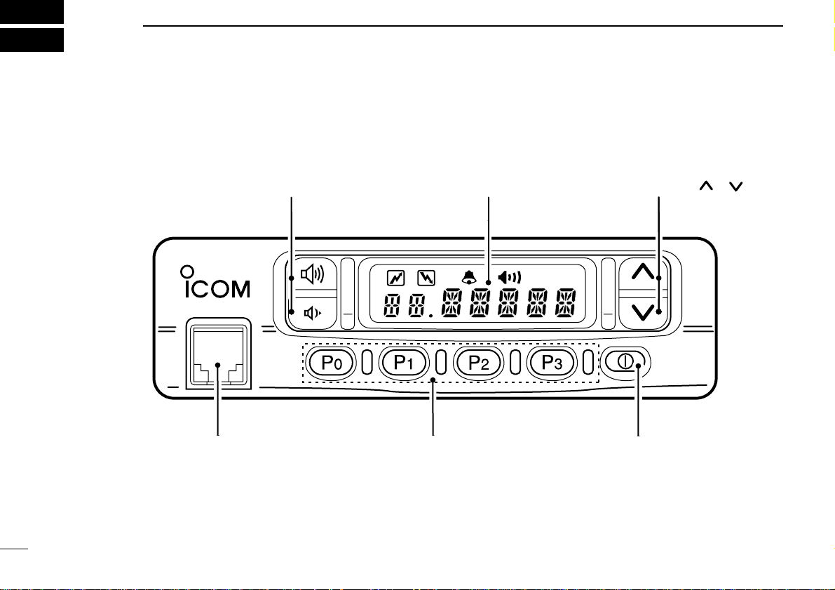
■Front panel
MICROPHONE
CONNECTOR
(P. 2)
PROGRAMMABLE
FUNCTION KEYS [P0],[P1],[P2],[P3]
(P. 3)
POWER SWITCH (P. 2)
FUNCTION DISPLAY (P. 2)
CH UP/DOWN KEYS []/[] (P. 3)
VOLUME UP/DOWN KEYS (P. 2)
Page 5
1
PANEL DESCRIPTION
2
VOLUME UP/ DO WN KEYS
Push to adjust the audio output level.
• Minimum audio level is pre-progr ammed.
CH UP/DOWN [ ]/[ ] KEYS
•Push to select the operating channel.
• Can be programmed for one of several functions by yourdealer.
POWER SWITCH
Turns the power ON and OFF.
• The following functions are available at power ON as options:
• Automatic scan start
• Password prompt
MICROPHONE CONNECTOR
Connect the supplied microphone or optional DTMF microphone for SmarTrunk II™ operation here.
NEVER connect other microphones. The pin assignments
may be different and the transceiver may be damaged.
MICROPHONE
The supplied microphone has a PTT switch and a hanger
hook.
• The following functions are available when the microphone is on or
off hook:
• Automatic scan start when hung on.
• Automatic priority channel selection when off.
• Sets to ‘Inaudible’ condition (mute condition) when hung on.
• Sets to ‘Audible’ condition (unmute condition) when off.
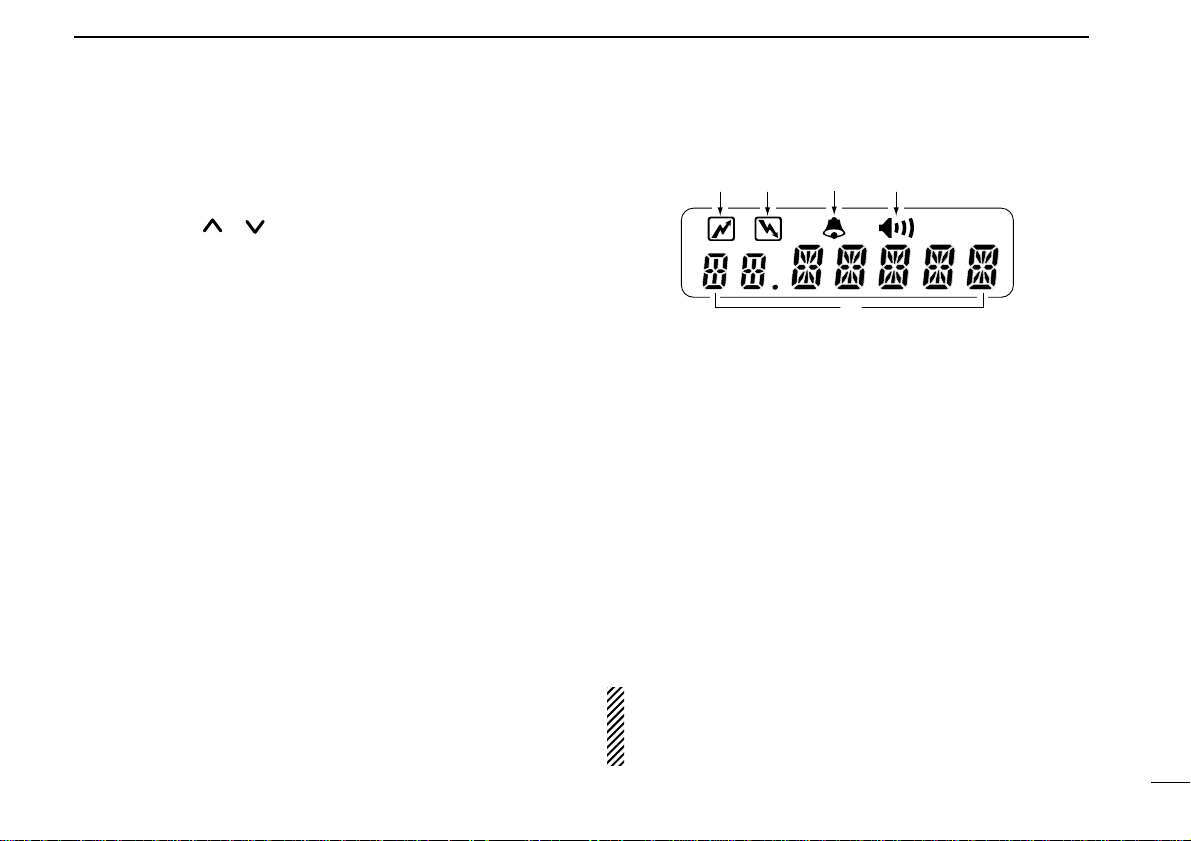
■Function display
q TRANSMIT INDICATOR
•Appears while transmitting or sending a 5-tone code.
• When internal temperature increases to a specific level,
the transmit indicator blinks to indicate that the power
down circuit has been activated.
w BUSY INDICATOR
Appears while the channel is busy.
e BELL INDICATOR
Appears or blinks when the specified 5-tone call is received.
r AUDIBLE INDICATOR
Appears when the channel is in the ‘Audible’ condition
(unmute condition).
t ALPHANUMERIC DISPLAY
NOTE: When the alphanumeric display blinks transmitting
becomes impossible. In this case check that the antenna is
not mis-matched or that DC battery voltage has not
dropped below 8 V.
wer
q
t
Page 6

1
3
PANEL DESCRIPTION
PRIORITY CHANNEL KEYS
Select priority A or priority B channel with each push.
BANK KEY
Select a bank (a group of 16 channels).
• When the optional UT-105 is installed, push one or
more times to select a channel bank for conventional channels or SmarTrunk II™ channels.
SCAN ST ART/ST OP KEY
Push this key to start scanning; and push again to
stop.
NOTE: Place the microphone on hook to start
scanning.
Take the microphone off hook to stop scanning.
Push and hold this key to indicate the scan group,
then push to select the desired group.
SCAN T AG KEY
Adds or deletes the selected channel to the scan
group.
BEEP
Push to turn the beep tones ON/OFF.
SCAN
TAG
■Programmable function keys
The following functions can be assigned to [P0], [P1], [P2],
[P3], [ ] and [] programmable function keys.
Consult your Icom Dealer or System operator for details concerning your transceivers programming.
In the following explanations, programmable function names
are bracketed, the specifc s witch used to activate the function
depends on programming.
CH UP AND DOWN KEYS
• Select an operating channel.
• Select a transmit code channel after pushing the
[
TX CH
] key.
• Select a DTMF channel after pushing the [
DTMF
]
key .
• Select a scan group after pushing and holding the
[
SCAN
] key.
OPERA TING CHANNEL KEYS
Select an operating channel directly.
CH UP
CH DN
PRI A
PRI B
BANK
CH 1
CH 2
CH 3
CH 4
BEEP
Page 7

1
LOCK KEY
Electronically locks all programmable keys except
the following:
•[
CALL
] (incl. CAL A and CAL B), [
MONI
] and
[
EMER
] keys.
MONITOR KEY
Activates one of (or two of) the follo wing functions on
each channel independently:
• Push and hold the key to unmute the channel (audio is
emitted; ‘Audible’ condition).
• Push the key to toggle the mute and unmute conditions
(toggles ‘Audible’ and ‘Inaudible’).
• Push the key to mute the channel (sets to ‘Inaudible’ only).
• Push the key to unmute the channel (sets to ‘Audible’
only).
• Push the key after the communication is finished to send a
‘reset code’.
NOTE: The unmute condition (‘Audible’ condition)
may automatically return to the mute condition
(‘Inaudible‘ condition) after a specified period.
WIDE/NARROW KEY
Push [W/N] to toggle bandwidth between wide or
narrow.
• This function is available for W/N versions only.
MONI
4
PANEL DESCRIPTION
OUTPUT POWER SELECTION KEYS
Select the transmit output power temporarily or permanently depending on the pre-setting.
• Ask your Dealer or System Operator for the output power
level for each selection.
T ALK AROUND KEY
Turns the talk around function ON and OFF.
• The talk around function equalizes the transmit frequency
to the receive frequency for mobile-to-mobile communication.
CALL KEYS
Transmit a 5-tone call.
• Call transmission is necessary before you call another station depending on your signaling system.
• The [CAL A] and/or [CAL B] keys may be available when
your system employs selective ‘Individual/Group’ calls.
Ask your System Operator which call is assigned to each
key.
EMERGENCY KEY
Push and hold the key to transmit an emergency call.
• If you want to cancel the emergency call, push (or push
and hold) the key again before transmitting the call.
• The emergency call is transmitted one time only or repeatedly until receiving a control code depending on the
pre-setting.
LOCK
HIGH
LOW2
LOW1
TA
CALL
CAL B
CAL A
EMER
W/N
Page 8

1
PANEL DESCRIPTION
5
TX CODE KEY
Select a transmit 5-tone code (station code) channel.
• Push and hold to changes the contents of the station code using []/[]keys.
• Push to selects a TX 5-tone code channel using
[]/[]keys after pushing this key.
TX CODE CHANNEL UP/DOWN KEY
Push to selects a TX code channel directory.
DTMF CHANNEL SELECT KEY
Push this key to select a DTMF channel.
• Push this key, then select the desired DTMF chan-
nel using the []/[]keys.
Push and hold this key to transmit the selected
DTMF code.
NOTE: DTMF channels 6 and 7 are used for ID
code and emergency code respectively, depending on your system set up.
Ask your System Operator or Dealer about DTMF
channels 6 and 7 before using these.
C. TONE CHANNEL ENTER KEY
Push this key then input a continuous tone memory
channel number via the keypad to change the tone
frequency.
ID MEMORY READ KEY
Recalls detected ID codes.
• Push this key, then push []/[]for selection.
• Up to 5 ID's are memorized.
Push and hold this key to erase all memorized IDs.
LIGHT
Push to select the backlight condition.
ON :Turns ON the backlight continuously.
OFF :Turns OFF the backlight.
AUTO :Tur ns ON/OFF depending on the ACC
socket pin 1 voltage.
ON: Low (0 V) OFF: High (12 V)
ATTENUATOR
Push to turn the attenuator function ON/OFF.
NOTE: The attenuator function protects desired
signals from distorting when excessively strong
signals, such as broadcast, pager signals, etc.
are nearby.
TRUNKING GROUP SWITCH
Push to select the Trunking group.
TX CH
CODE
DTMF
TONE
ID MR
LITE
ATT
GRP
Page 9

■Channel selection
Several types are a vailable, and the channel selection method
may differ according to your system set up.
NON-BANK TYPE:
Push the []/[]keys to select the desired operating
channel, in sequence; or,
push one of the [
CH 1] to [CH 4] keys to select these channels
directly.
BANK-TYPE:
Push [
BANK] to select the desired bank number.
AUT OMA TIC SCAN TYPE:
Channel setting is not necessary for this type. When turning
the power ON, the transceiver automatically starts scanning.
Scanning stops when receiving a call or when taking the microphone off hook.
■T urning power ON
q Push [KI] to turn the power ON.
• A power-up alert tone sounds for
about 1 sec. and an opening message may appear.
w If the transceiver is programmed
for a start up passcode, input
digit codes as directed by your
System operator.
• The keys in the diagram below can
be used for password input:
• The transceiver detects numbers in the same block as identical.
Therefore “1234” and “6789” are the same.
e When the “PWORD” indication does not clear after inputting
4 digits, the input code number may be incorrect. Turn
power off and start over in this case.
OPERATION
2
6
Opening message may
differ depending on the
pre-setting.
Input your password if
this display appears.
KEY
NUMBER
P0 P1 P2 P3
0
5
1
6
2
7
3
8
4
9
Page 10

■Receiving and transmitting
RECEIVING:
q Push [K
I
] to turn the power ON.
w Push []/[]to select a channel.
e When receiving a call, adjust the volume [UP] or [DOWN]
to a comfortable listening level.
TRANSMITTING:
r Take the microphone off hook.
• 5-tone mute may be released (the ‘audible’ condition is selected
and “” appears).
• A priority channel may be selected automatically.
t Wait for the channel to become clear.
• The channel is busy when “” appears.
y Push the [CALL] key when initiating a call from your side.
• Coded audio may be heard from the transceiver, then “” ap-
pears.
• This operation may not be necessary depending on your signaling system. Ask your System Operator or Dealer.
u While pushing and holding [PTT], speak into the micro-
phone at your normal voice level.
i Release [
PTT] to receive.
2
OPERATION
7
IMPORTANT: To maximize the readability of your signal:
(1) pause briefly after pushing [
PTT], (2) hold the trans-
ceiver 15 to 20 cm from your mouth, then speak into the
microphone at a normal voice level.
D Transmitting notes
• T ransmit inhibit function
The transceiver has several lockout/inhibit functions which restrict transmission under the following conditions:
• The channel is in mute condition (‘Inaudible’ condition; “”
does not appear).
• Channel is busy.
• No matched (or matched) CTCSS is received.
• The selected channel is a ‘receive only’ channel.
• Time-out timer
After continuous transmission for a pre-programmed period,
the time-out timer is activated causing the transceiver to stop
transmitting and automatically select receive.
• Penalty timer
Once the time-out timer is activated, transmission is further
inhibited for a period determined by the penalty timer.
Page 11

2
OPERATION
8
D Tx code channel selection
If the transceiver has a [
TX CH
] key, display can be toggled
between the operating channel number (or name) and Tx
code channel number (or name). When the Tx code channel
number (or name) is displayed, the []/[]keys select the
Tx code channel.
TO SELECT A TX CHANNEL:
q Push [
TX CH
] — a Tx code channel appears.
w Push []/[]to select the desired Tx code channel.
e Push [
CALL
] to transmit the selected Tx code.
r Push [
TX CH
] again to return to the channel display.
D Tx code number selection
If the transceiver has a [
CODE
] key, Tx code contents can be
changed within the allowable digits.
TO SELECT A TX CODE:
q Push [
CODE
] — a Tx code number appears and an allow-
able digit blinks.
w Push []/[]to select the desired number at the blink-
ing digit.
e Push [
CODE
] to enter the selected number.
r Repeat steps w and e to input all allowed digits.
t Push [
CALL
] to transmit the selected Tx code.
D DTMF transmission
If the transceiver has a [
DTMF
] key, the automatic DTMF
transmission function is available. Up to 7 DTMF channels
may be available.
q Push [
DTMF
] to select the display
as at right.
w Push []/[]to select the de-
sired DTMF channel.
e Push and hold [
DTMF
] to transmit the DTMF code on the
selected DTMF channel.
Page 12

CONNECTION AND MAINTENANCE
3
9
■Rear panel and connection
Antenna
red: +
black: _
Supplied DC
power cable
Optional speaker
(SP-10)
Optional cable
(OPC-617)
t
q
w
e
r
Page 13

3
CONNECTION AND MAINTENANCE
10
⁄ ANTENNA CONNECTOR
Connects to an antenna. Ask your Dealer about antenna
selection and placement.
(See p. 12)
¤ MICROPHONE HANGER
Connect the supplied microphone hanger to the vehicle’s
ground for on/off hook microphone functions.
(See p. 2)
‹ DC POWER RECEPTACLE
Connects to a 12 V DC battery. Pay attention to polarities.
NEVER connect to a 24 V battery . This could damage the
transceiver.
› EXTERNAL SPEAKER JACK
Connect a 4–8 Ω external speaker, if desired.
fi OPTIONAL CABLE (OPC-617)
Connect an external modem unit, LCD backlight control,
etc.
■Supplied Accessories
q Microphone ...................... 1
(Some versions may not be sup-
plied with a microphone
)
w Microphone hanger and
screw set ..................... 1 set
e Microphone hanger cable . 1
r DC power cable ..................1
IC-F310/F410: OPC-345
IC-F320/F420: OPC-346
t Mounting bracket .............. 1
y Bracket bolt ....................... 4
u Mounting screw (M5×12) ... 4
i Self-tapping screw
(M5×20) ............................. 4
o Flat washer ....................... 4
!0 Spring washer ................... 4
!1 Nut .................................... 4
!2 Fuse ................................. 2
IC-F310/F410: 15 A
IC-F320/F420: 20 A
!3 Function name stickers*
(1705 LCD SEAL(A)) ..............1
D *Function name stickers
There are no names on the programmable function keys since the
needed functions can be assigned to these keys.
Attach the supplied function name stickers above the appropriate
keys.
12
3
4
5
6
7
8
90 A B
C
LCD-STICKER
Page 14

■Mounting the transceiver
The universal mounting bracket supplied with your transceiver
allows overhead mounting. Please read the following instructions carefully.
•Mount the transceiver securely with the 4 supplied screws to
a thick surface which can support more then 1.5 kg.
3
CONNECTION AND MAINTENANCE
11
■Optional UT-96/UT-105 instal-
lation
The optional UT-96/UT-105 units install as follows:
q Turn power OFF, then disconnect the DC power cable.
w Unscrew the 4 screws, then remove the bottom cover.
e Install the unit as shown in the diagram below.
r Replace the bottom cover and screws, then the DC power
cable.
NOTE: The sponge supplied with the UT-105 is for the
IC-F30/F40 series transceivers only.
Flat washer
Spring washer
When using
self-tapping screws
Page 15

3
CONNECTION AND MAINTENANCE
12
■ Antenna
A key element in the performance of any communication system is an antenna. Ask your Dealer about antennas and the
best places to mount them.
■ Fuse replacement
Two fuses are installed in the supplied DC power cable. If a
fuse blows or the transceiver stops functioning, track down
the source of the problem, if possible, and replace the damaged fuse with a new, rated one.
❑Fuse rating IC-F310/F410: 15 A, IC-F320/F420: 20 A
■ Cleaning
If the transceiver becomes dusty or dirty, wipe it clean with a
dry, soft cloth.
AVOID the use of solvents such as benzene or alcohol, as they may damage transceiver surfaces.
■ Optional OPC-617 installation
Install the OPC-617 as shown below.
OPTIONAL CABLE PIN ASSIGNMENT
t r e w q
o i u y
q
LCD backlit cont. IN
w AF OUT
e Det. AF OUT
r Mod. IN
t PTT control IN
y Horn drive cont. OUT
u AF GND
i Det. AF GND
o Mod. GND
Page 16

OPTIONAL SmarTrunk II™ OPERATION
4
13
■SmarT runk II™ and
conventional modes
This transceiver is capable of SmarTrunk II™ functions.
The optional UT-105 allows communication in conventional
channels or SmarTrunk II™ channels. Select a channel bank
for SmarTrunk II™ before trunking operation.
•Push [
BANK
] one or more times to select a channel bank for
conventional channels or SmarTrunk II™ channels.
• Scanning starts when a channel bank for SmarTrunk II™ is se-
lected.
• Contact your Dealer for channel bank details.
NOTE: Connect an optional HM-100T DTMF MICRO-
PHONE. Contact your Dealer for details.
■SmarT runk II™ operation
These features are enabled by a Dealer or System Operator
and may not be av ailab le in y our system.Contact your Dealer
for details.
D Placing a telephone call
Enter the phone number followed by [1], [M].
• A high-pitched beep indicates that the number is accepted.
• When the called party answers, push the [PTT] switch to talk, and
release it to listen.
D Calling another local system subscriber
Enter the subscriber number followed by [3], [M].
• A high-pitched beep indicates that the number is accepted.
• You hear ringing, then two short beeps when the subscriber an-
swers.
• If the other subscriber is on another call or out of range, you hear a
fast busy signal and the call terminates automatically.
D Receiving a call
When you hear ringing, push [M] to answer.
• For a group call, you hear a short ring followed by two short beeps.
You do not have to answer a group call to hear it over the air.
Page 17

4
OPTIONAL SmarTrunk II™ OPERATION
14
D Terminating a call
After completing a call, push [#] to disconnect (hang up).
IMPORTANT: If one person in the conversation terminates
a call, all participants will be cut off.
D Last number redial
Push [M], [M] to automatically redial the last number called.
• A high-pitched beep indicates that the number is accepted.
D Memory speed-dialing
To automatically dial a commonly used number from memory:
•Push [M] followed by the memory location (0–9).
D Turbo SpeeDial
To automatically dial a commonly used number with one
push:
•Push one of the turbo SpeeDials ([A], [B], [C] or [D]).
D Programming memory speed dial
q Push and hold [M] until you hear a high-pitched beep.
w Enter the memory location (0–9, A, B, C, D), the telephone
or subscriber number, then [1], [M] (or [3], [M] if f or another
system subscriber).
• A high-pitched beep indicates successful programming.
• Memories [A]–[D] are used for the Turbo SpeeDial.
D System busy indication
If all channels are busy, three low beeps sound after you initiate a call. Try the call again later.
D PTT dispatch operation
q Push [PTT] once (without dialing) to initiate a dispatch call.
w Begin talking after you hear three beeps (one short, high-
pitched, two very-short, low-pitched).
e Receiving a dispatch call is indicated by the same three-
beep sequence.
• It is not necessary to push [M] to answer a dispatch call.
D Emergency call
Push [0], [M] to initiate an emergency call.
• Contact your dealer for details.
Page 18

4
OPTIONAL SmarTrunk II™ OPERATION
15
D Clear channel alerting
If all channels are busy, the transceiver automatically begins
searching for an open channel and beeps ev ery ten seconds.
When two short beeps (low-pitched, then high-pitched) are
heard, a channel is available .Push [M], [M] immediately to redial the last number.
NOTE: For additional operating instructions, contact your
Dealer or System Operator.
Page 19

5
EXTERNAL SPEAKERS
SP-5
Large speaker for good audio
quality.
Input impedance: 4 Ω
Max. input power: 5 W
SP-10
Compact and easy-to-install.
Input impedance: 4 Ω
Max. input power: 5 W
HM-100T/TA
DTMF microphone.
HM-100
Normal microphone.
16
OPTIONS
UT-96 5-TONE UNIT
Provides 2-tone/5-tone signaling .
UT-105
SmarTrunk II™ Logic Board
Provides SmarTr unk II™ capabili-
ties.
OPC-617
ACC CABLE
Allows you to connect to an external terminal.
Page 20

6-9-16 Kamihigashi, Hirano-ku, Osaka 547-0002 Japan
A-5458D-1EX-e
Printed in Japan
© 1997 by Icom Inc.
 Loading...