


INSTRUCTION MANUAL
VHF MOBILE TRANSCEIVER
iF1721/D
iF1821/D
UHF MOBILE TRANSCEIVER
iF2721/D
iF2821/D
Icom Inc
This model is IC-F1821/D This device complies with Part 15 of the FCC Rules. or IC-F2821/D Operation is subject to the condition that this device
does not cause harmful interference.

IMPORTANT
READ ALL INSTRUCTIONS carefully and com-
pletely before using the transceiver.
SAVE THIS INSTRUCTION MANUAL — This
instruction manual contains important operating instructions for the IC-F1721/D, F1821/D, F2721/D and F2821/D VHF/ UHF MOBILE TRANSCEIVERS.
EXPLICIT DEFINITIONS
WORD |
DEFINITION |
|
RWARNING |
Personal injury, fire hazard or electric shock |
|
may occur. |
||
|
|
|
CAUTION |
Equipment damage may occur. |
|
NOTE |
If disregarded, inconvenience only. No risk |
|
of personal injury, fire or electric shock. |
||
|
||
|
|
Icom, Icom Inc. and the 
 logo are registered trademarks of Icom Incorporated (Japan) in the United states, the United Kingdom, Germany, France, Spain, Russia and/or other countries.
All other products or brands are registered trademarks or trademarks of their respective holders.
PRECAUTION
RWARNING! NEVER connect the transceiver to an AC outlet. This may pose a fire hazard or result in an electric shock.
NEVER connect the transceiver to a power source of more than 16 V DC such as a 24 V battery. This connection will ruin the transceiver.
NEVER cut the DC power cable between the DC plug and fuse holder. If an incorrect connection is made after cutting, the transceiver might be damaged.
NEVER place the transceiver where normal operation of the vehicle may be hindered or where it could cause bodily injury.
NEVER allow children to touch the transceiver.
NEVER expose the transceiver to rain, snow or any liquids.
USE the specified microphone only. Other microphones have different pin assignments and may damage the transceiver.
DO NOT use or place the transceiver in areas with temperatures below –30°C (–22°F) or above +60°C (+140°F), or in areas subject to direct sunlight, such as the dashboard.
i

AVOID operating the transceiver without running the vehicle’s engine. The vehicle’s battery will quickly run out if the transceiver transmits while the vehicle’s engine OFF.
AVOID placing the transceiver in excessively dusty environments.
AVOID placing the transceiver against walls. This will obstruct heat dissipation.
AVOID the use of chemical agents such as benzine or alcohol when cleaning, as they damage the transceiver surfaces.
BE CAREFUL! The transceiver will become hot when operating continuously for long periods.
For U.S.A. only
CAUTION: Changes or modifications to this transceiver, not expressly approved by Icom Inc., could void your authority to operate this transceiver under FCC regulations.
ABOUT APCO PROJECT 25
This device made under license under one or more of the following US patents: #4,590,473, #4,636,791, #5,148,482, #5,185,796, #5,271,017, #5,377,229.
The IMBE™ voice coding Technology embodied in this product is protected by intellectual property rights including patent rights, copyrights and trade secrets of Digital Voice Systems, Inc. This voice coding Technology is licensed solely for use within this Communications Equipment. The user of this Technology is explicitly prohibited from attempting to decompile, reverse engineer, or disassemble the Object Code, or in any other way convert the Object Code into a human-readable form. U.S. Pat. Nos. #5,870,405, #5,826,222, #5,754,974, #5,701,390, #5,715,365, #5,649,050, #5,630,011, #5,581,656, #5,517,511, #5,491,772, #5,247,579, #5,226,084, #5,195,166.
ii

TABLE OF CONTENTS
IMPORTANT ....................................................................................... |
i |
EXPLICIT DEFINITIONS .................................................................... |
i |
PRECAUTION .................................................................................... |
i |
ABOUT APCO PROJECT 25 ............................................................. |
ii |
TABLE OF CONTENTS .................................................................... |
iii |
1 PANEL DESCRIPTION .............................................................. |
1–7 |
■ Front panel .................................................................................. |
1 |
■ Function display .......................................................................... |
2 |
■ Programmable function keys ...................................................... |
3 |
2 BASIC OPERATION ................................................................ |
8–13 |
■ Turning power ON ....................................................................... |
8 |
■ Channel selection ....................................................................... |
8 |
■ Call procedure ............................................................................ |
9 |
■ Receiving and transmitting ......................................................... |
9 |
DTransmitting notes .................................................................. |
10 |
DTX code channel selection ..................................................... |
10 |
DTX code number edit .............................................................. |
11 |
DIndividual ID code selection.................................................... |
12 |
DTalkgroup ID code selection ................................................... |
12 |
DDTMF transmission ................................................................ |
12 |
■ User set mode .......................................................................... |
13 |
■ Scrambler function .................................................................... |
13 |
3 BIIS OPERATION ................................................................... |
14–24 |
■ Default setting ........................................................................... |
14 |
■ Receiving a call ......................................................................... |
14 |
DIndividual call.......................................................................... |
14 |
DGroup call ............................................................................... |
15 |
DDisplaying the received call record......................................... |
15 |
■ Transmitting a call ..................................................................... |
16 |
DUsing call memory.................................................................. |
16 |
DCalling back from the queue channel ..................................... |
16 |
DDirect code entry .................................................................... |
17 |
■ Receiving a message ............................................................... |
18 |
DReceiving a status message .................................................. |
18 |
DReceiving an SDM (Short Data Message) ............................. |
18 |
DReceived message selection.................................................. |
19 |
■ Transmitting a status ................................................................. |
20 |
DGeneral................................................................................... |
20 |
DTransmitting a status .............................................................. |
20 |
■ Transmitting an SDM (Short Data Message) ............................. |
21 |
DGeneral................................................................................... |
21 |
DTransmitting an SDM.............................................................. |
21 |
DProgramming an SDM memory.............................................. |
22 |
■ Position data transmission ........................................................ |
23 |
■ Printer connection ..................................................................... |
23 |
■ Digital ANI ................................................................................. |
23 |
■ Auto emergency transmission ................................................... |
23 |
■ Stun function ............................................................................. |
24 |
■ BIIS indication ........................................................................... |
24 |
■ Priority A channel selection ....................................................... |
24 |
■ Horn output ............................................................................... |
24 |
4 CONNECTION AND MAINTENANCE ................................... |
25–29 |
■ Rear panel connection .............................................................. |
25 |
■ Supplied Accessories ................................................................ |
26 |
■ Mounting the transceiver ........................................................... |
27 |
■ Optional UT-111 installation ...................................................... |
27 |
■ Optional UT-109 or UT-110 installation ..................................... |
28 |
■ Optional OPC-617 installation ................................................... |
28 |
■ Antenna...................................................................................... |
29 |
■ Fuse replacement ..................................................................... |
29 |
■ Cleaning .................................................................................... |
29 |
■ Options ..................................................................................... |
29 |
5 SAFETY TRAINING INFORMATION ........................................... |
30 |
iii

|
|
PANEL DESCRIPTION 1 |
■Front panel |
|
1 |
q |
w |
e* |
Icom Inc
o |
i |
u y t |
r |
e*
IC-F1721/D F2721/D
IC-F1821/D F2821/D
qAF VOLUME CONTROL KNOB
Rotate the knob to adjust the audio output level.
• Minimum audio level is pre-programmed.
wFUNCTION DISPLAY (p. 2)
Displays a variety of information, such as an operating channel number/name, 5-tone code, DTMF numbers and audible condition, etc.
eDIAL or UP/DOWN KEYS
•IC-F1721/D, F2721/D: DIAL
Rotate to select an operating channel, etc.
•IC-F1821/D, F2821/D: UP/DOWN Keys
Push to select an operating channel, etc.
*The desired function can be assigned by your dealer. (p. 3)
r 10-KEYPAD (IC-F1821/D or IC-F2821/D only) The keypad allows you to enter digits to:
•Select memory channels, tone channels and DTMF codes (when in the DTMF code channel selection mode)
•Set TX codes and BIIS status number
•Input text message for SDM operation
•Start up with a password
•Input the Individual ID code for digital operation.
t BUSY INDICATOR
Lights green while receiving a signal, or when the squelch is open.
1
1 PANEL DESCRIPTION
yPOWER SWITCH [POWER]
Push to turn the power ON and OFF.
•The following functions are available at power ON as options:
-Automatic scan start
-Password prompt
-Set mode
uTRANSMIT INDICATOR
Lights red while transmitting.
iDEALER-PROGRAMMABLE KEYS
Desired functions can be programmed independently by your dealer. (p. 3)
In this instruction manual, these keys are from the left, called [P0]/[P1]/[P2]/[P3]/[P4].
oMICROPHONE CONNECTOR
Connect the supplied microphone or optional DTMF microphone.
NEVER connect non-specified microphones. The pin assignments may be different and the transceiver may be damaged.
D MICROPHONE
The supplied microphone has a PTT switch and a hanger hook.
•The following functions are available when the microphone is on or off hook:
-Automatic scan start when on hook.
-Automatic priority channel selection when off hook.
-Sets to ‘Inaudible’ condition (mute condition) when on hook.
-Sets to ‘Audible’ condition (unmute condition) when off hook.
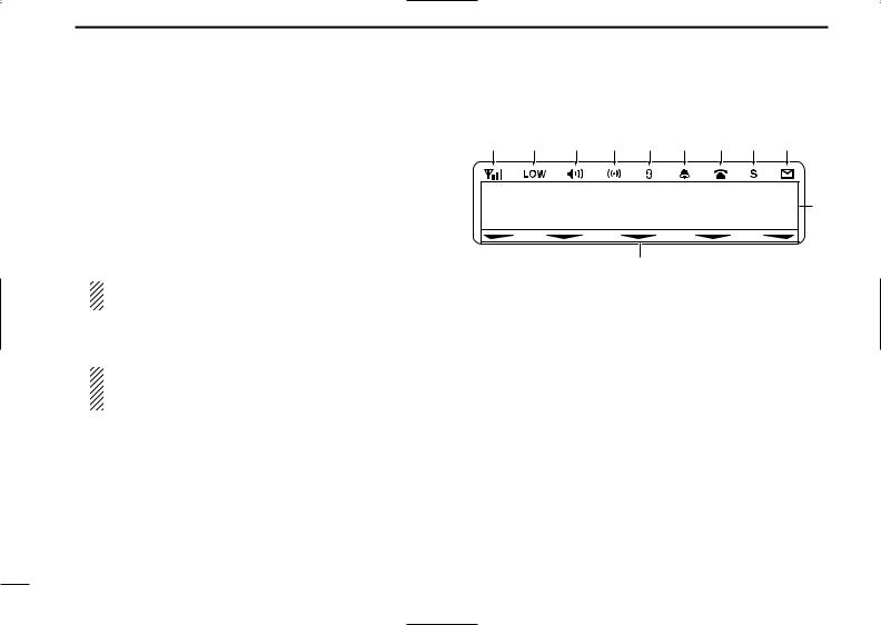
■ Function display
q w e r t y u i o
136.1 Nar
!
!1
qSIGNAL STRENGTH INDICATOR
Indicates relative signal strength level.
wLOW POWER INDICATOR
Appears when low output power is selected.
eAUDIBLE INDICATOR
Appears when the channel is in the ‘audible’ (unmute) condition.
Appears when the specified 2/5-tone/BIIS code is received.
rCOMPANDER INDICATOR
Appears when the compander function is activated.
tSCRAMBLER INDICATOR
Appears when the voice scrambler function is activated.
2

yBELL INDICATOR
Appears/blinks when the specific 2/5-tone/BIIS code is received, according to the pre-programming.
uCALL CODE MEMORY INDICATOR
Appears when the call code memory is selected.
iSCROLL INDICATOR
Appears when a received SDM including more than 12 characters is displayed.
oSDM INDICATOR
Appears when an SDM is received, or a transmit SDM is selected.
!0ALPHANUMERIC DISPLAY
Displays an operating channel number, channel name, Set mode contents, DTMF code, etc.
The indication mode can be selected from 1 line or 2 lines. Ask your dealer for details.
In this instruction manual, the LCD illustration is described using the 2 lines indication mode.
!1ACTIVATED KEY INDICATOR
Appears above the key assigned as [DIGITAL] key when that key has been activated.
PANEL DESCRIPTION 1
■ Programmable function keys |
1 |
The following functions can be assigned to [DIAL]*, [UP],
[DOWN], [P0], [P1], [P2], [P3] and [P4] programmable function keys.
Consult your Icom dealer or system operator for details concerning your transceivers programming.
If the programmable function names are bracketed in the following explanations, the specific key is used to activate the function depends on the programming.
*The functions you can assign to [DIAL] are limited. (Only functions marked with can be assigned.)
CH UP AND DOWN KEYS
Push (or Rotate)* to select an operating channel.
Push (or Rotate)* to select a transmit code channel after pushing [TX Code CH Select].
Push (or Rotate)* to select a DTMF channel after pushing [DTMF Autodial].
Push (or Rotate)* to select a scan group after pushing and holding [Scan A Start/Stop]/[Scan B Start/Stop].
Push (or Rotate)* to select a BIIS code, status number or SDM after pushing [Digital].
Push (or Rotate)* to select an Individual ID code or
Talkgroup ID code after pushing [Individual] or [Talkgroup]. *Rotate when this function is assigned to [DIAL].
ZONE UP AND DOWN KEY (This function is for [DIAL] only)
Rotate to select the desired zone.
3

1 PANEL DESCRIPTION
ZONE SELECT KEY
Push this key, then select the desired zone using [CH Up]/ [CH Down].
What is “zone”?— The desired channels are assigned into a zone according to the intended use. For example, ‘Staff A’ and ‘Staff B’ are assigned into a “Business” zone, and ‘John’ and ‘Cindy’ are assigned into a “Private” zone.
SCAN A KEY
This key’s operation depends on the Power ON Scan setting.
When the power ON scan function is turned OFF;
Push to start and cancel scanning operation. In case of transmission during scan, cancels scanning.
When the power ON scan function is turned ON;
Push to pause scanning. Scanning resumes after a specified time period has passed. In case of transmission during scan, pauses scanning. Scanning resumes after a specified time period has passed after the transmission is finished.
Push and hold this key for 1 sec. to indicate the scan group, then select the desired group using [CH Up]/[CH Down].
SCAN B KEY
Push to start and cancel scanning operation. In case of transmission during scan, pauses scanning. Scanning resumes after a specified time period has passed after the transmission is finished.
Push and hold this key for 1 sec. to indicate the scan group, then select the desired group using [CH Up]/ [CH Down].
SCAN TAG KEY
Push to add or delete the selected channel to/from the scan group.
PRIORITY CHANNEL KEYS
Push to select Priority A or Priority B channel.
Push and hold [Prio A (Rewrite)] to rewrite the Prio A channel.
MR-CH 1/2/3/4 KEYS
Push to select an operating channel directly.
MONITOR KEY
Mute and release the CTCSS (DTCS) or 2-tone squelch mute. Open any squelch/deactivate any mute while pushing this key. (LMR operation only)
Activates one of (or two of) the following functions on each channel independently: (PMR or BIIS PMR operation only)
•Push and hold to un-mute the channel (audio is emitted; ‘Audible’ condition).
•Push to mute the channel (sets to ‘Inaudible’ only).
•Push to un-mute the channel (sets to ‘Audible’ only).
•Push after the communication is finished to send a ‘reset code’.
NOTE: The un-mute condition (‘Audible’ condition) may automatically return to the mute condition (‘Inaudible‘ condition) after a specified period depending on programming.
4

PUBLIC ADDRESS KEY
While in the hailer mode, push this key for the audio output via the hailer amplifier. Ask your dealer for details.
While in the normal mode, the audio output via the cable can be controlled from the transceiver separately from [VOL] control knob when an optional OPC-617 ACC CABLE is installed.
•This audio output can be used as a ‘public address’ function when an external audio amplifier and speaker are connected additionally.
•Push this key, then speak into the microphone while pushing the PTT switch.
•[CH Up]/[CH Down] allow you to set the audio output level from minimum to maximum.
RX SPEAKER KEY
While in the hailer mode, the external speaker drive function is also available simultaneously when the external connections are made for the ‘public address’ function. The received audio can be heard via the external speaker when this key is pushed.
•This function is useful when you are out of the vehicle.
•The audio output level is linked to the transceiver’s volume control.
LIGHT KEY
Push to turn the transceiver’s backlight ON temporarily when the backlight function is turned OFF in user set mode.
LOCK KEY
Push and hold to electronically lock all programmable keys except the following:
[Call] (incl. Call A and Call B), [Moni(Audi)] and [Emergency].
PANEL DESCRIPTION 1
OUTPUT POWER SELECTION KEY |
1 |
|
Push to select the transmit output power temporarily or per- |
||
|
||
manently, depending on the pre-setting. |
|
• Ask your dealer for the output power level for each selection.
C.TONE CHANNEL ENTER KEY
Push to select the continuous tone channel using [CH Up]/ [CH Down] to change the tone frequency/code setting after pushing this key. The selected channel remains set as the continuous tone channel until another channel is designated as such.
TALK AROUND KEY
Turn the talk around function ON and OFF.
•The talk around function equalizes the transmit frequency to the receive frequency for transceiver-to-transceiver communication.
WIDE/NARROW KEY
Push to toggle the IF bandwidth between wide and narrow.
•The wide passband width can be selected from 25.0 or 20.0 kHz using the CS-F1700 CLONING SOFTWARE. (PMR or BIIS PMR operation only) Ask your Dealer for details.
DTMF AUTODIAL KEY
Push to enter the DTMF channel selection mode. Then select the desired DTMF channel using [CH Up]/[CH Down].
After selecting the desired DTMF channel, push this key to transmit the DTMF code.
5

1 PANEL DESCRIPTION
DTMF RE-DIAL KEY
Push to transmit the last-transmitted DTMF code.
CALL KEYS
Push to transmit a 2/5-tone/BIIS ID code.
•Call transmission is necessary before calling another station depending on your signalling system.
•[Call A] and/or [Call B] may be available when your system employs selective ‘Individual/Group’ calls. Ask your dealer which call is assigned to each key.
EMERGENCY KEYS
Push and hold to transmit an emergency call.
When [Emergency Single (Silent)] or [Emergency Repeat (Silent)] is pushed, an emergency call is transmitted without a beep emission and LCD indication change.
•If you want to cancel the emergency call, push (or push and hold) the key again before transmitting the call.
•The emergency call is transmitted one time only or repeatedly until receiving a control code depending on the pre-setting.
TX CODE ENTER KEY (PMR or BIIS PMR operation only) Push to enter the ID code edit mode directly, for both 5-tone and MSK. Then set the desired digit using [CH Up]/ [CH Down] or 10-keypad*. (p. 11)
*IC-F1821/D or IC-F2821/D only
TX CODE CHANNEL SELECT KEY
Push to enter the ID code channel selection mode directly. Then set the desired channel using [CH Up]/[CH Down]. (p. 10)
During ID code channel selection mode, push for 1 sec. to enter the ID code edit mode for 5-tone and MSK. Then set the desired digit using [CH Up]/[CH Down] or 10-keypad*. (p. 11)
*IC-F1821/D or IC-F2821/D only
TX CODE CHANNEL UP/DOWN KEYS
Push (or Rotate)* to select a TX code channel directly. *Rotate when this function is assigned to [DIAL].
ID MEMORY READ KEY (PMR or BIIS PMR operation only)
Recalls detected ID codes.
•Push this key, then select the ID code using [CH Up]/[CH Down].
•Up to 5 ID’s are memorized.
Push and hold to erase the selected ID’s.
VOICE SCRAMBLER FUNCTION
Push to toggle the voice scrambler function ON and OFF.
COMPANDER KEY
Push to toggle the compander function ON and OFF.
The compander function reduces noise components from the transmitted audio to provide clear communication.
6
USER SET MODE KEY
Push and hold to enter user set mode.
•During user set mode, push this key to select an item, and change the value or condition using push [CH Up]/[CH Down].
Push and hold this key again to exit user set mode.
User set mode is also available via the ‘Power ON function.’ Refer to p. 13 also.
OPT OUT KEYS
Push to control the output signal level from the optional unit connector.
DIGITAL KEY (BIIS operation only)
Push to select the call ID list, transmit message and standby condition. Toggles between queue channel and received message record indication after queue channel is selected.
Push and hold to select queue channel indication.
STATUS UP/DOWN KEYS (BIIS operation only)
While in the standby condition, push (or rotate)* to display the transmit status indication and select a status number.
When a received SDM is displayed, push (or rotate)* to cancel the automatic scroll and scroll the message manually.
When an SDM that contains more than 12 characters is displayed, push (or rotate)* to scroll the message manually.
*Rotate when this function is assigned to [DIAL].
PANEL DESCRIPTION |
1 |
DFor Digital mode operation only |
1 |
INDIVIDUAL KEY |
|
Push to enter the individual ID code selection mode directly. Then select the desired individual ID code using [CH Up]/ [CH Down]. (p. 12)
Push to stop the beep emission when receiving a matched individual ID code.
TALKGROUP KEY
Push to enter the talkgroup ID code selection mode directly. Then select the desired talkgroup ID code using [CH Up]/ [CH Down]. (p. 12)
Push to stop the beep emission when receiving a matched talkgroup ID code.
7
 Loading...