

Page 1

INSTRUCTION MANUAL
DUAL BAND FM TRANSCEIVER
iC- 2710h
Page 2
IMPORTANT
CAUTIONS
READ ALL INSTRUCTIONS carefully and completely before
using the transceiver.
SAVE THIS INSTRUCTION MANUAL—This instruction manual contains important operating instructions for the
IC-2710H.
RWARNING! NEVER connect the transceiver to an
AC outlet. This may pose a fire hazard or result in an electric
shock.
RWARNING! NEVER operate the transceiver while
driving a vehicle. Safe driving requires your full attention—
anything less may result in an accident.
NEVER connect the transceiver to a power source of more
EXPLICIT DEFINITIONS
The explicit definitions below apply to this instruction manual.
WORD DEFINITION
RWARNING
CAUTION
NOTE
i
Personal injury, fire hazard or electric shock
may occur.
Equipment damage may occur.
If disregarded, inconvenience only. No risk
of personal injury, fire or electric shock.
The IC-2710H Europe versions comply with essential requirements of the 89/336/EEC directive for Electromagnetic
Compatibility. This compliance is based on conformity with
the ETSI specification prEIS300 684 (EMC product standard
for Commercially Available Amateur Radio Equipment).
than 16 V DC. This connection will ruin the transceiver.
NEVER connect the transceiver to a power source using
reverse polarity. This connection will ruin the transceiver.
NEVER cut the DC power cable between the DC plug and
fuse holder. If an incorrect connection is made after cutting,
the transceiver might be damaged.
NEVER place the transceiver where normal operation of
the vehicle may be hindered or where it could cause bodily
injury.
NEVER let objects impede the operation of the cooling fan
on the rear panel.
DO NOT push the PTT when not actually desiring to transmit.
Page 3
DO NOT allow children to play with any radio equipment
➀➁ ➂
➃
➄
➅➉
➆
➇
➈
containing a transmitter.
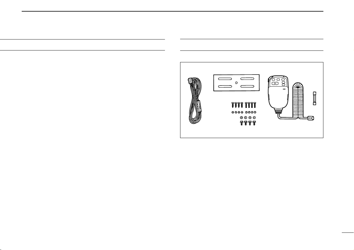
UNPACKING
During mobile operation,
without running the vehicle’s engine. When transceiver power
is ON and your vehicle’s engine is OFF, the vehicle’s battery
will soon become exhausted.
DO NOT operate the transceiver
BE CAREFUL! The transceiver will become hot when
operating it continuously for long periods.
AVOID using or placing the transceiver in areas with tem-
peratures below –10°C (+14°F) or above +60°C (+140°F) or
in areas subject to direct sunlight, such as the dashboard.
AVOID the use of chemical agents such as benzine or al-
cohol when cleaning, as they can damage the transceiver
surfaces.
USE Icom microphones only (supplied or optional). Other
manufacturer’s microphones have different pin assignments
and may damage the transceiver.
Accessories included with the transceiver:
Qty.
➀ DC power cable (OPC-346)............................................. 1
➁ Mobile mounting bracket ................................................. 1
➂ Microphone (HM-98)........................................................ 1
➃ Fuse (20 A)...................................................................... 1
➄ Knob bolt (M4 x 8) ........................................................... 4
➅ Mounting bolt (M5 x 12)................................................... 4
➆ Nut (M5)........................................................................... 4
➇ Spring washer (M5)......................................................... 4
➈ Flat washer (M5).............................................................. 4
➉ Self-tapping screws (A0 5 x 16)....................................... 4
ii
Page 4

TABLE OF CONTENTS
IMPORTANT .................................................................................... i
EXPLICIT DEFINITIONS ................................................................. i
CAUTIONS ...................................................................................... i
UNPACKING ................................................................................... ii
TABLE OF CONTENTS ................................................................. iii
1 PANEL DESCRIPTION ....................................................... 1 – 8
■ Front panel ........................................................................................... 1
■ Function display ................................................................................... 3
■ Rear panel ............................................................................................ 5
■ Microphone .......................................................................................... 6
■ Microphone keypad .............................................................................. 7
2 INSTALLATION ................................................................. 9 – 14
■ Installation methods ............................................................................. 9
■ Location .............................................................................................. 10
■ Single body installation ...................................................................... 10
■ Microphone connection ...................................................................... 11
■ Separate installation ........................................................................... 11
■ Optional MB-58 installation ................................................................ 12
■ Battery connection ............................................................................. 13
■ DC power supply connection ............................................................. 13
■ Antenna installation ............................................................................ 14
3 SETTING A FREQUENCY .............................................. 15 – 19
■ Preparation ......................................................................................... 15
■ Lock functions .................................................................................... 16
■ Using a tuning dial .............................................................................. 17
■ Using [Y]/[Z] switches ....................................................................... 17
■ Tuning step selection ......................................................................... 18
■ Using the keypad ............................................................................... 19
4 BASIC OPERATION ....................................................... 20 – 26
■ Receiving ........................................................................................... 20
■ Monitor function .................................................................................. 21
■ Audio mute function ........................................................................... 21
■ Avionics band receive ........................................................................ 21
■ Sub band access ................................................................................ 22
■ Sub band mute/sub band busy beep ................................................. 23
■ Para-watch ......................................................................................... 24
■ Transmitting ........................................................................................ 25
■ Selecting the output power ................................................................. 25
■ Crossband full duplex ......................................................................... 26
■ One-touch PTT function ..................................................................... 26
5 REPEATER OPERATION ............................................... 27 – 31
■ Operation ........................................................................................... 27
■ Subaudible tones ............................................................................... 29
■ Offset frequency ................................................................................. 30
■ Auto repeater ..................................................................................... 31
6 MEMORY OPERATION .................................................. 32 – 36
■ General description ............................................................................ 32
■ Memory channel selection ................................................................. 32
■ Programming a memory channel ....................................................... 33
■ Programming a memory channel via the microphone .......................... 34
■ Transferring memory contents ........................................................... 35
■ Memory clearing ................................................................................. 36
7 CALL CHANNEL OPERATION ...................................... 37 – 38
■ Calling up a call channel contents ...................................................... 37
■ Transferring call channel contents ..................................................... 37
■ Programming a call channel ............................................................... 38
8 SCRATCH PAD MEMORY .............................................. 39 – 40
■ What is a scratch pad memory? ......................................................... 39
iii
Page 5

■ Calling up a scratch pad memory ....................................................... 39
■ Transferring scratch pad memory contents ........................................ 40
9 SCAN OPERATION ........................................................ 41 – 46
■ Scan types ......................................................................................... 41
■ Start/stop scan ................................................................................... 42
■ Programming scan edges .................................................................. 43
■ Programming scan edges via the microphone ................................... 44
■ Skip channel setting ........................................................................... 45
■ Scan resume condition ....................................................................... 46
10 PRIORITY WATCH .......................................................... 47 – 48
■ Priority watch types ............................................................................ 47
■ Priority watch operation ...................................................................... 48
11 DTMF MEMORY ENCODER .......................................... 49 – 52
■ Programming a DTMF code ............................................................... 49
■ Clearing the DTMF memory contents ................................................ 49
■ Programming a DTMF code via the microphone ............................... 50
■ Transmitting a DTMF code ................................................................. 51
■ DTMF speed ...................................................................................... 52
12 POCKET BEEP AND TONE SQUELCH ........................ 53 – 55
■ Pocket beep operation ....................................................................... 53
■ Tone squelch operation ...................................................................... 54
■ Tone scan ........................................................................................... 55
13 PAGER AND CODE SQUELCH ..................................... 56 – 62
■ Pager function .................................................................................... 56
■ Code channels ................................................................................... 57
■ Code programming ............................................................................ 58
■ Pager operation .................................................................................. 59
■ Code squelch function ........................................................................ 61
■ Code squelch operation ..................................................................... 62
14 EXTERNAL DTMF REMOTE .......................................... 63 – 64
15 OPTIONAL UNIT INSTALLATION ......................................... 65
■ Optional unit installation ..................................................................... 65
16 WIRELESS OPERATION ................................................ 66 – 71
■ Connection ......................................................................................... 66
■ HM-90
■ EX-1759 installation ........................................................................... 67
■ HM-90 switches .................................................................................. 68
■ Microphone address ........................................................................... 71
WIRELESS MICROPHONE
............................................................ 66
17 OTHER FUNCTIONS ...................................................... 72 – 74
■ Beep tones on/off ............................................................................... 72
■ Time-out timer .................................................................................... 72
■ Auto power-off .................................................................................... 73
■ Cooling fan setting ............................................................................. 73
■ Microphone [F-1]/[F-2] keys ............................................................... 74
■ Display dimmer setting ....................................................................... 74
■ Demonstration display ........................................................................ 74
18 MAINTENANCE .............................................................. 75 – 77
■ Troubleshooting .................................................................................. 75
■ Fuse replacement .............................................................................. 77
■ Partial resetting .................................................................................. 77
■ Total resetting ..................................................................................... 77
19 SPECIFICATIONS .................................................................. 78
20 OPTIONS ........................................................................ 79 – 80
21 MODE ARRANGEMENT CHART ................................... 81 – 82
iv
Page 6
1
V MHz
SCAN
S.MW MW
LOW DUP POWER DTMF T
MONI
SQL
MONI
SQL
SET L
VOL
SET D
VOL
M CALL
PRIO
V MHz
SCAN
S.MW MW
M CALL
PRIO
LOCK
VFO
CALLMRSUB
BAND
F-2
F-1
Function display (p. 3)
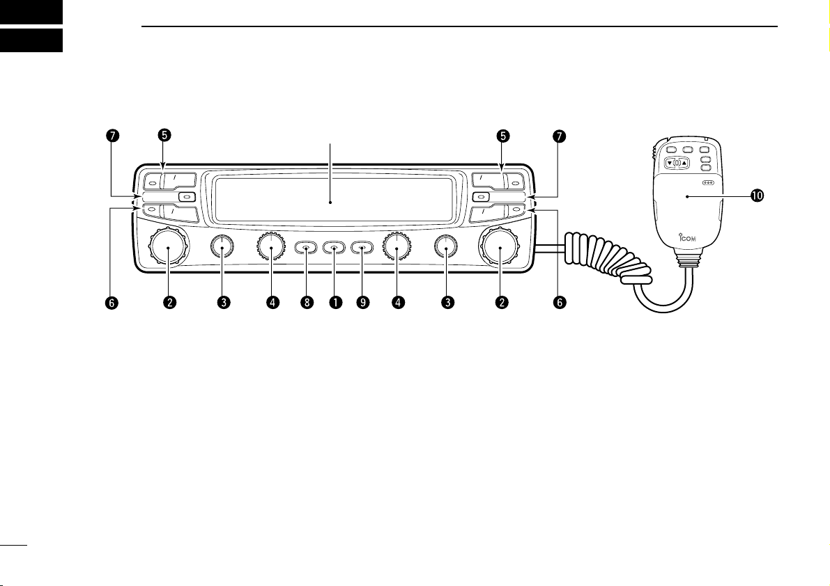
PANEL DESCRIPTION
■ Front panel (remote controller)
q POWER SWITCH [POWER]
Turns power ON and OFF when pushed for 1 sec.
w TUNING DIALS
➥ Select the operating frequency (p. 17), the memory
channel (p. 32), the contents of the set mode display
(p. 82) and the scanning direction. (p. 42)
➥ Select the main band when pushed. (p. 15)
➥ When the sub band is selected, activate the sub band
function when pushed and held. (p. 22)
➥ When the main band is selected, change the operating
band (for para watch) when pushed and held. (p. 24)
e SQUELCH CONTROLS [SQL(MONI)]
➥ Vary the squelch level. (p. 20)
• RF attenuator activates and increases the attenuation when
rotated clockwise to the center position and further.
➥ Toggles squelch opened and closed when pushed.
• Transmit frequency is automatically selected when squelch
opens.
r VOLUME CONTROLS [VOL(SET L)]/[VOL(SET D)]
➥ Adjust the audio levels. (p. 20)
➥ Select set mode when pushed. (p. 82)
➥ Toggles the lock function ON/OFF when pushed and
held [SET
(L)]. (p. 16)
➥ Allows you to adjust the display brightness when
1
pushed and held [SET
(D)]. (p. 74)
Page 7
t VFO/MHz SWITCHES [V/MHz(SCAN)]
➥ Select and toggle VFO mode and 1 MHz tuning display.
➥ Start a scan when pushed and held. (p. 42)
y MEMORY/CALL CHANNEL SWITCHES
[M/CALL(PRIO)]
➥ Select and toggle memory mode or a call channel.
(pgs. 32, 37)
➥ Activate the priority watch function when pushed and
held. (p. 47)
u SELECT MEMORY/MEMORY WRITE SWITCHES
[S.MW(MW)]
➥ Select a memory channel for programming. (p. 33)
➥ Program selected memory when pushed and held. (p. 33)
i OUTPUT POWER/DUPLEX SWITCH [LOW(DUP)]
➥ Each push changes the output power selection. (p. 25)
• There are 3 output powers available: low, mid and high.
➥ Push and hold to select a duplex setting. (p. 27)
• There are 3 duplex settings available: minus duplex (“–
DUP” appears, plus duplex (“+ DUP” appears) and simplex.
o DTMF/TONE SWITCH [DTMF(T)]
➥ Turns DTMF memory encoder ON and OFF for au-
topatch operation. (p. 49)
• When an optional UT-49 is installed, activates the DTMF
memory, pager or code squelch function in sequence.
➥ Turns the subaudible tone encoder ON and OFF for re-
peater access when pushed and held. (p. 27)
• When an optional UT-104 is installed, activates the subaudible tone encoder, pocket beep or tone squelch function in
sequence.
PANEL DESCRIPTION
!0 MICROPHONE
➥ To connect the supplied microphone, detach the front
panel in advance.
➥ Multi-function keypad can be accessed by removing
the keypad cover. (p. 7)
• Be careful not to lose the cover.
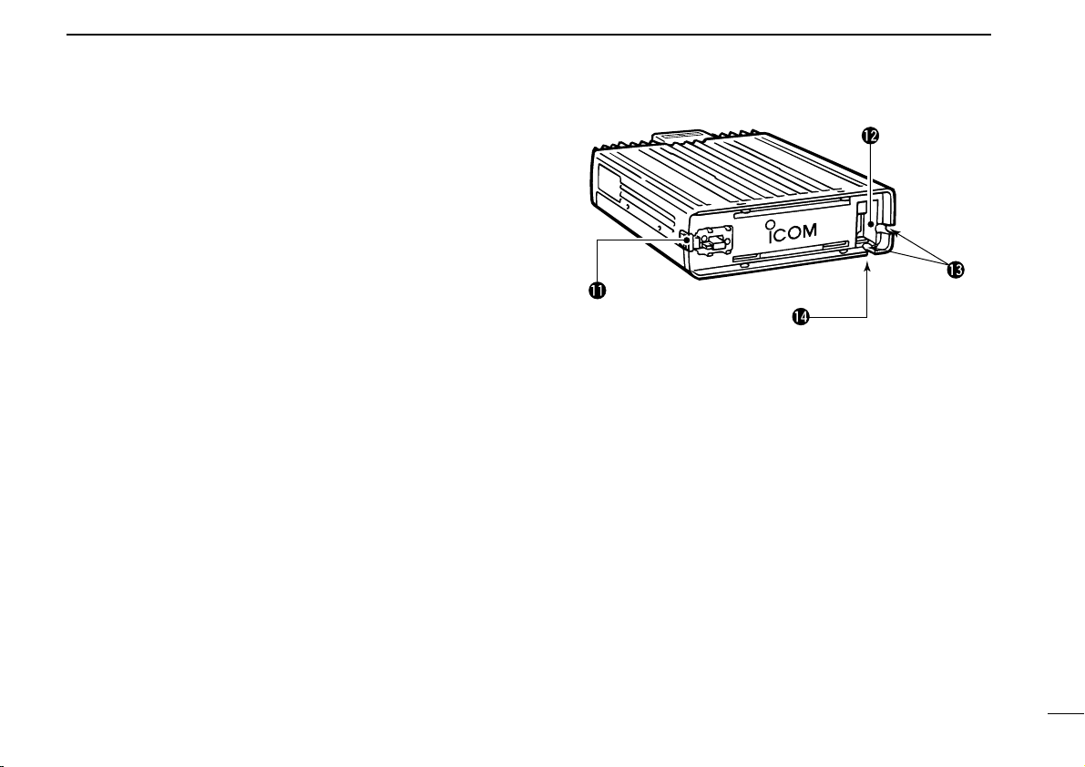
!1 FRONT PANEL RELEASE LATCH
While pushing this latch, slide the front panel to the left to
remove it.
!2 MICROPHONE CONNECTOR
Connect the supplied microphone or optional EX-1759
FRARED RECEIVER
!3 CABLE GUTTERS
Pass the microphone cable through one of the gutters
when attaching the front panel.
!4 MICROPHONE RELEASE
Push to release the microphone.
. (p. 11)
1
IN
-
2
Page 8
1
BUSY
LOW
LOW
MUTE
PRIO
DUP
SKIP SKIP
BUSY
MUTE
PRIO
–
T SQL
DUP
–
TSQL
TOT
AO
REMO
q
wert y ui
o
!0
!1
q
o
!0
!1
!2!3!4!5!6 !2!3!4!5!6!7
werty
PANEL DESCRIPTION
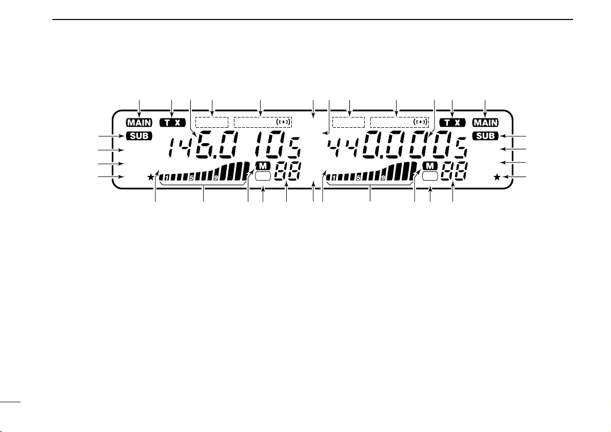
■ Function display
q SUB BAND ACCESS INDICATORS (p. 22)
Appear when the sub band access function is activated
and indicate the function control band via the microphone
and some front panel switches (except transmitting).
w MAIN BAND INDICATORS (p. 15)
Indicate the main band for transmit and function control.
e TRANSMIT INDICATORS (p. 25)
➥ Appear while transmitting.
➥ Flash while transmitting with the one-touch PTT func-
3
tion (p. 26).
r FREQUENCY READOUTS
Show the operating frequency, set mode contents, etc.
• The decimal point of the frequency flashes while scanning.
(p. 42)
•“d” appears in place of the 100 MHz while the DTMF memory
function is in use; when optional units are installed, “P, ” or “C”
appears in place of the 100 MHz while the pager or code
squelch functions are in use, respectively. (pgs. 49, 59, 61)
t DUPLEX INDICATORS (p. 27)
“DUP–” or “DUP” appear during semi-duplex operation (repeater operation).
y TONE INDICATORS
➥ “T” appears while the subaudible tone encoder is in
use. (p. 27)
➥ “T SQL” appears while the optional tone squelch func-
tion is in use. (p. 54)
➥ “T SQLS” appears while the optional pocket beep
function is in use. (p. 53)
Page 9

PANEL DESCRIPTION
1
u EXTERNAL DTMF CONTROL INDICATOR (p. 63)
Appears when the optional external DTMF control function
is in use.
• Available for the U.S.A. version only.
i TOT (TIME-OUT TIMER) INDICATOR (p. 72)
Appears while the time-out timer has been activated.
o AUDIO MUTE INDICATORS (p. 21)
Appear when the audio mute function is activated via microphone control.
• This function is cancelled when any switch or control is operated.
!0 PRIORITY WATCH INDICATORS (p. 48)
Appear while the priority watch is activated; flash while the
watch is paused.
!1 OUTPUT POWER INDICATORS (p. 25)
➥ “LOW” appears for low output power. (5 W)
➥ “LOW ★” appears for mid output power. (10 W)
➥ No indicator appears for high output power.
!2 MEMORY CHANNEL READOUTS
➥ Show the selected memory channel numbers. (p. 32)
➥ Only 2 capital “L”’s appear while the frequency lock
function is in use. (p. 16)
➥ A capital “C” appears while on a call channel (p. 37)
➥ “L1–L3” appear when a scratch pad memory is se-
lected. (p. 39)
➥ A small “c” appears when VFO mode is selected from
the call channel or a scratch pad memory (pgs. 37, 39)
!3 SKIP INDICATORS (p. 45)
Appear when the displayed memory channel is specified
as a skip channel.
!4 MEMORY INDICATORS (p. 32)
Appear when memory mode is selected.
!5 S/RF INDICATORS (p. 25)
➥ Show the relative signal strength while receiving sig-
nals.
➥ Show the output power selection while transmitting.
!6 BUSY INDICATORS (p. 20)
Appear while a signal is being received or the squelch is
open.
!7 AUTO POWER-OFF INDICATOR (p. 73)
Appears while the auto power-off function is in use.
4
Page 10
1
q
w
e
r
PANEL DESCRIPTION
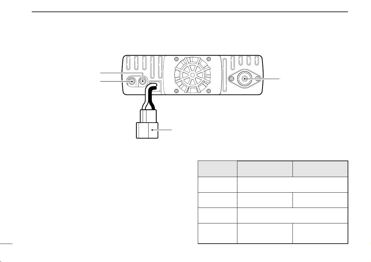
■ Rear panel
q ANTENNA CONNECTOR [ANT]
Accepts a 50 Ω dual band antenna with a PL-259 connector. (p. 14)
w SPEAKER JACK 1 [144 MHz SP]
Connects a 4–8 Ω speaker, if required. Outputs the 144
MHz band’s audio. See the table at right for details.
e SPEAKER JACK 2 [430(440) MHz SP]
Connects a 4–8 Ω speaker, if required. Outputs both
band’s audio when [430(440) MHz SP] has no connection.
r POWER RECEPTACLE [DC13.8V]
Accepts 13.8 V DC with the supplied DC power cable.
5
D Speaker information
Connected
speaker
With no external speakers
[144 MHz SP]
only
[430(440) MHz
SP] only
2 external
speakers
VHF band audio UHF band audio
Internal speaker (mixed audio)
External speaker
External speaker (mixed audio)
External speaker via
[144 MHz SP]
Internal speaker
External speaker via
[430(440) MHz SP]
Page 11
PANEL DESCRIPTION
LOCK
VFO
CALLMRSUB
BAND
MW
FUNC
A
CLR
D-OFF
B
SET
PTT-M
3
PRIO
DTMF
6
LOW
AFC-OFF
2
SCAN
CSQL
5
MID
AFC
1
MONI
PGR
4
HIGH
T-OFF
C
ENT
TSQL
9
SIMP
16
KEY LOCK
#
TSQLS
8
DUP+
TONE-2
0
TONE
7
DUP
TONE-1
F-2
F-1
DTMF-S
MUTE
D
SQLSQLVOLVOL
Mic element
q
w
e
r
t
y
u
i
o
1
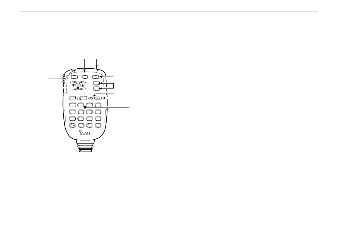
■ Microphone
q UP/DOWN SWITCHES [Y]/[Z]
➥ Push either switch to change the operating frequency,
➥ Push and hold either switch to start scanning. (p. 42)
w PTT SWITCH
➥ Push and hold to transmit; release to receive. (p. 25)
memory channel, set mode contents, etc. (pgs. 17, 32)
➥ Toggles between transmitting and receiving while the
one-touch PTT function is in use. (p. 26)
e VFO SWITCH [VFO(LOCK)]
➥ Push to select VFO mode.
➥ Push and hold to toggle the lock function ON and OFF.
r MEMORY SWITCH [MR(CALL)]
➥ Push to select memory mode. (p. 32)
➥ Push and hold to select the call channel. (p. 37)
t ACTIVITY INDICATOR
Lights red while a key is pushed; lights green while the
one-touch PTT function is in use.
y BAND SWITCH
➥ Push to toggle the main band. (p. 15)
➥ Push and hold to turn the sub band access function ON
and OFF. (p. 22)
u FUNCTION SWITCHES [F-1]/[F-2] (p. 74)
Assign your desired key function from the front panel
switches.
• Default settings are VHF and UHF tuning dials to [F-1] and [F-2],
respectively for quick band selection.
i FUNCTION INDICATOR
➥ Lights yellow while [FUNC] is activated—indicates the
secondary function of switches can be accessed.
➥ Lights green when [DTMF-S] is activated—DTMF sig-
nals can be transmitted with the keypad. (p. 51)
o KEYPAD
Used for controlling the transceiver, transmitting a DTMF
encoder, etc. See pgs. 7 and 8 for function details.
6
Page 12
1
FUNC
DTMF-S
PANEL DESCRIPTION
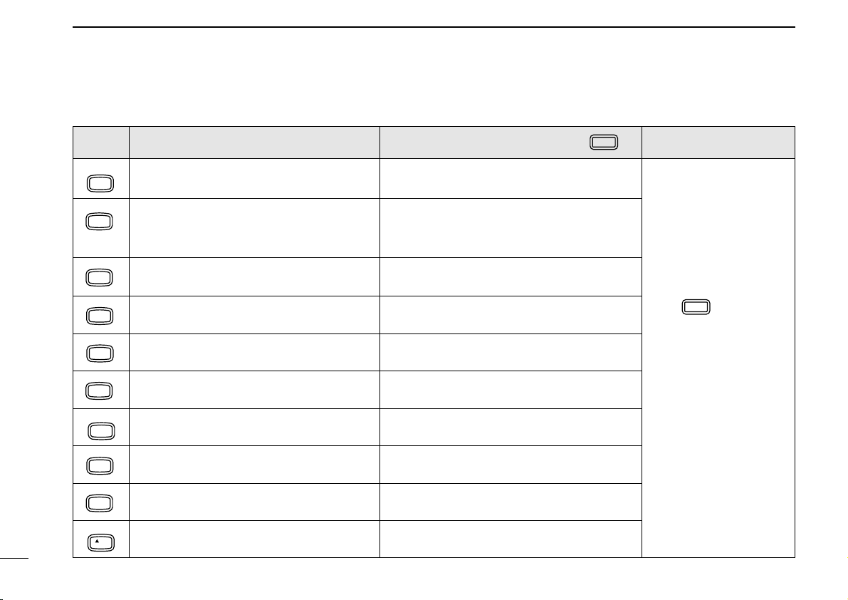
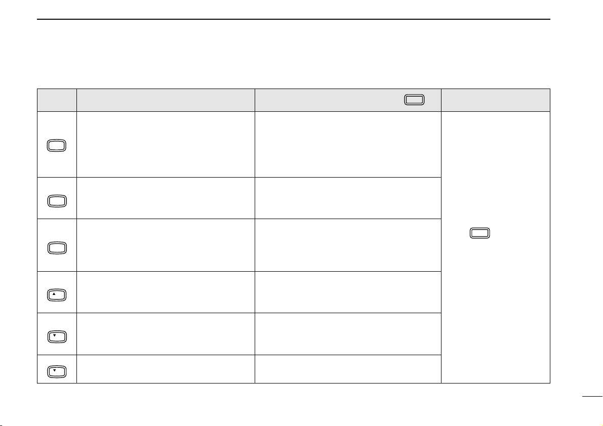
■ Microphone keypad
KEY
AFC
MONI
AFC-OFF
SCAN
2
FUNCTION
Toggles between opening and closing the
1
accessed band’s squelch. (p. 20)
• Starts and stops scanning. (p. 42)
• Starts tone scan when an optional tone
SECONDARY FUNCTION (after )
No secondary function.
No secondary function.
OTHER FUNCTIONS
squelch is in use. (p. 55)
PTT-M
PRIO
3
PGR
HIGH
4
CSQL
MID
5
DTMF
LOW
6
TONE
DUP–
7
TSQLS
DUP+
8
TSQL
SIMP
9
TONE-2
0
VOL
Starts and stops priority watch. (p. 48)
Selects high output power. (p. 26) Turns the optional pager function ON.(p. 59)
Selects middle output power. (p. 26) Turns the optional code squelch function
Selects low output power. (p. 26)
Selects –duplex. (p. 28)
Selects +duplex. (p. 28)
Selects simplex (p. 28)
Increases the audio output. (p. 20)
Turns the one-touch PTT function ON and
OFF. (p. 26)
ON. (p. 62)
Turns the DTMF memory encoder function
ON. (p. 50)
Turns the subaudible tone encoder ON.
(p. 28)
Turns the optional pocket beep function ON.
(p. 53)
Turns the optional tone squelch function
ON. (p. 54)
While being pushed, transmits a 1750 Hz
tone. (p. 28)
After :
Transmit the appropriate
DTMF code or push [1] to
[8] to transmit the DTMF
memory contents when
the DTMF memory encoder is activated. (p. 51)
7
Page 13
PANEL DESCRIPTION
FUNC
DTMF-S
1
KEY FUNCTION
• Clears a digit before entry. (p. 19)
• Cancels the scan, priority watch, pager,
MW
CLR
code squelch or DTMF memory function.
A
(pgs. 42, 48, 51, 59, 62)
D-OFF
SET
Enters set mode and advances the set
mode selection order. (p. 82)
B
• Sets the keypad for numeral input.
T-OFF
ENT
C
• Decreases the set mode selection order
after entering set mode. (p. 82)
MUTE
SQL
16
KEY LOCK
TONE-1
Increases the squelch level. (p. 20)
• The [SQL] control on the front panel has prior-
D
ity when rotated.
Decreases the squelch level. (p. 20)
• The [SQL] control on the front panel has prior-
#
SQL
ity when rotated.
Decreases the audio output. (p. 20) Sends a 1750 Hz tone signal for 1 sec.
VOL
M
(p. 19)
SECONDARY FUNCTION (after )
• Writes the VFO contents into the memory
channel or call channel. (pgs. 34, 38)
• Advances the memory channel number
when continuously pushed after programming is completed. (p. 34)
Turns the pager, code squelch, DTMF memory or DTMF remote function OFF.
(pgs. 59, 62, 63)
Turns the subaudible tone encoder, pocket
beep or tone squelch OFF. (pgs. 28, 53, 54)
Mutes both band’s audio signals. (p. 21)
• Mute function is released when any operation is
performed.
Locks the digit keys on the keypad (including
the A–D, # and
keys. (p. 16)
M
(p. 28)
OTHER FUNCTIONS
After :
Transmit the appropriate
DTMF code. (p. 51)
8
Page 14
2
INSTALLATION
■ Installation methods
D Single body installation
• It is not necessary to purchase a mounting bracket. The
supplied mounting bracket (or optional MB-17A) can be
used for installation.
9
D Separate installation
Front panel
Main body
• Optional OPC-600
OPC-601 (7.0 m; 23.0 ft) is necessary.
• Optional MB-58
for front panel mounting.
• Optional MB-65
front panel mounting possibilities (MB-58 is necessary).
• Optional OPC-440
OPC-647 (2.5 m; 8.2 ft) are available to extend the microphone cable.
• Optional OPC-441
able to extend the speaker cable.
SEPARATION CABLE
REMOTE CONTROLLER BRACKET
MOUNTING BASE
MICROPHONE CABLE
SPEAKER CABLE
(3.5 m; 11.5 ft) or
is available for increasing
(5.0 m; 16.4 ft) and
(5.0 m; 16.4 ft) is avail-
is available
Page 15
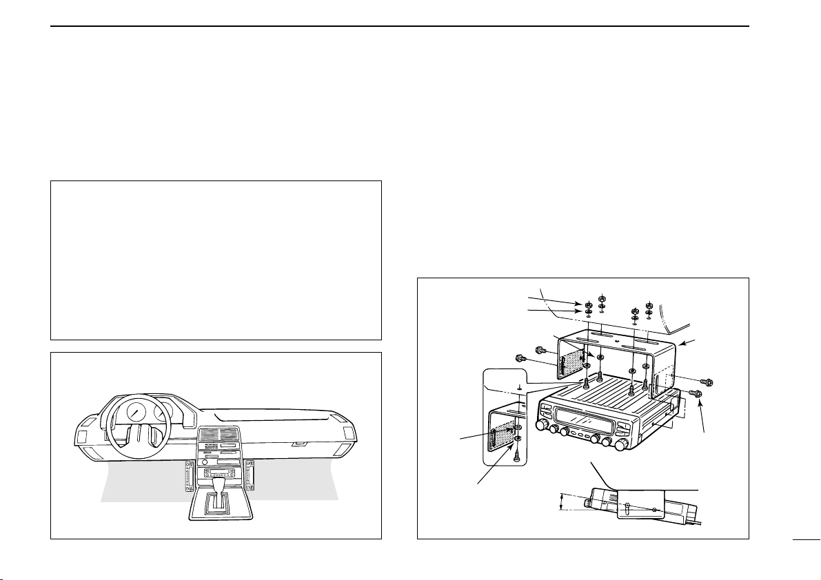
INSTALLATION
20°
Mounting nut
Mounting
bracket
When using
self-tapping
screws.
Nut
Spring washer
Flat washer
Flat washer
Spring
washer
2
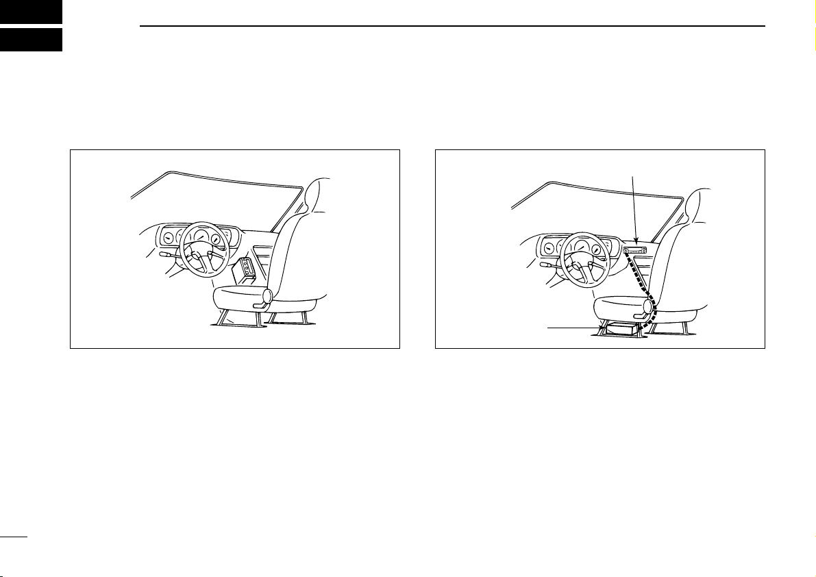
■ Location
Select a location which can support the weight of the transceiver and does not interfere with driving in any way. We recommend the locations shown in the diagram below.
NEVER place the transceiver or remote controller where
normal operation of the vehicle may be hindered or where
it could cause bodily injury.
NEVER place the transceiver or remote controller where
air bag deployment may be obstructed.
DO NOT place the transceiver or remote controller where
hot or cold air blows directly onto it.
AVOID placing the transceiver or remote controller in di-
rect sunlight.
• EXAMPLE INSTALLATION LOCATIONS
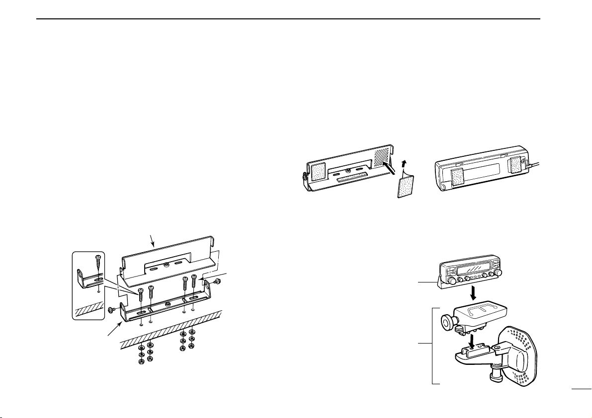
■ Single body installation
➀ Drill 4 holes where the mounting bracket is to be installed.
• Approx. 5.5–6 mm (3⁄16 in) when using nuts; approx. 2–3 mm (1⁄16
in) when using self-tapping screws.
➁ Insert the supplied screws, nuts and washers through the
mounting bracket and tighten.
➂ Adjust the angle for the clearest view of the function dis-
play.
10
Page 16
2
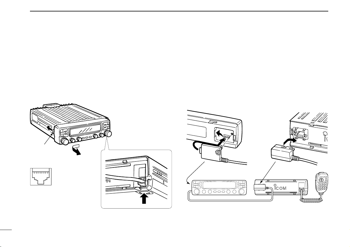
mic release
Push
Release
button
OPC-600 or OPC-601
Rear of front panel Main body
➇➀
INSTALLATION
■ Microphone connection
The microphone connector is located behind the front panel.
Connect the supplied microphone as follows:
➀ Push the release button, then detach the remote controller
as shown below.
➁ Connect the supplied microphone to the microphone con-
nector.
Microphone pin assignments
➀ 8 V OUT
➁ Freq. up/down
➂ 8 V control IN
➃ PTT
➄ Mic AF (–)
➅ Mic AF (+)
➆ Ground
➇ Data IN
■ Separate installation
Using an optional OPC-600/601
panel can be separated from the main body, doubling as a remote controller.
SEPARATION CABLE
➀ Detach the front panel as shown at left.
➁ Connect a separation cable to the front panel and to the
main body using the supplied screws as illustrated below.
, the front
11
➂ Reattach the remote controller to the main body.
➃ To remove the microphone, push the release button as
above.
Page 17
■ Optional MB-58 installation
Bracket
When using selftapping screws.
Mounting
base
Mounting
bolt
MB-58 IC-2710H remote controller
MB-58
MB-65
Adjust the viewing
angle for maximum
visibility of the
function display.
INSTALLATION
2
The optional MB-58
able for separate installation.
REMOTE CONTROLLER BRACKET
➀ Drill 2 or 4 holes where the bracket or mounting base is to
be installed, respectively.
• Approx. 4 mm (1⁄8 in) when using nuts; approx. 1–2 mm (1⁄16 in)
when using self-tapping screws.
➁ Insert the supplied screws, bolts and washers through the
mounting base and tighten.
➂ Adjust the angle for the clearest view of the function dis-
play and tighten 2 screws when the mounting base is used.
is avail-
➃ Attach the supplied Velcro pads (large) to the remote con-
troller and bracket.
➄ Attach the supplied Velcro pad (small) or rubber pad to the
bracket as shown below; then attach the remote controller.
D When using the MB-65
12
Page 18
2
INSTALLATION
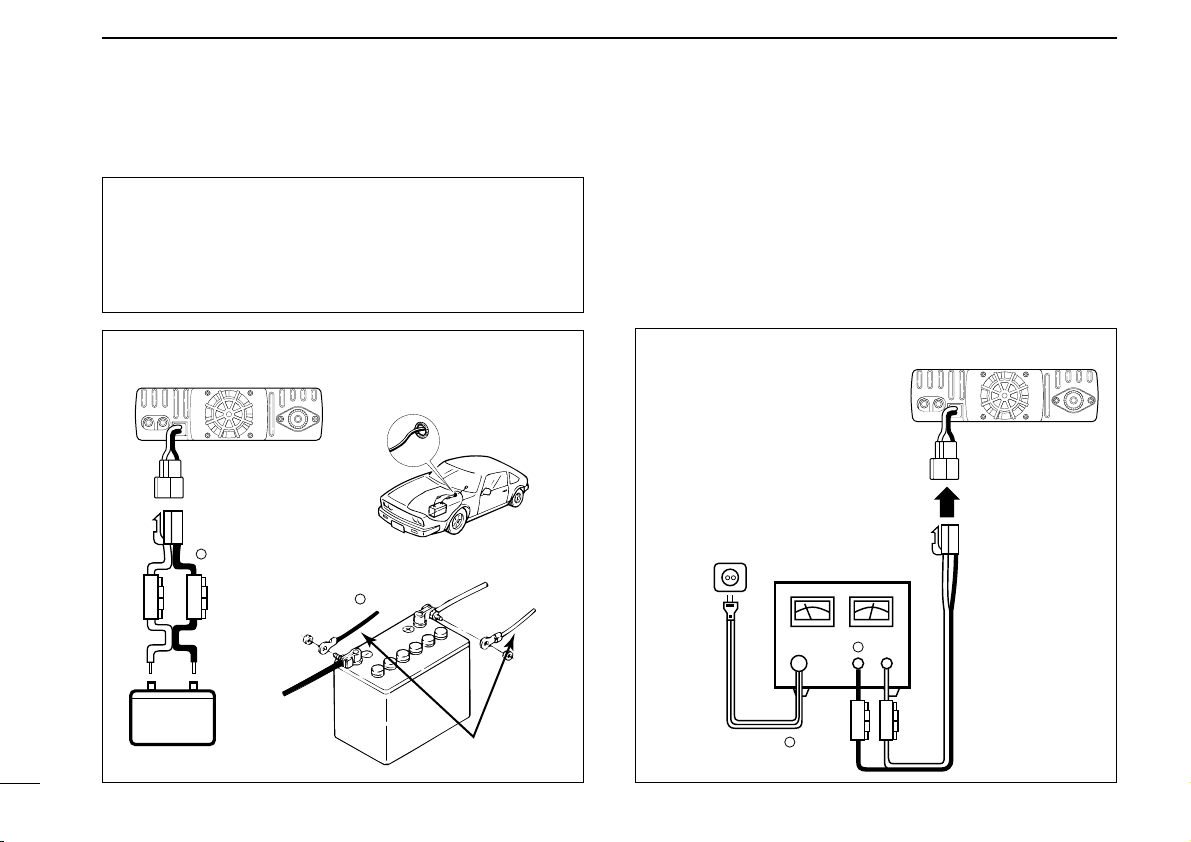
■ Battery connection ■ DC power supply connection
13
NEVER connect the transceiver directly to a 24 V battery.
DO NOT use the cigarette lighter socket for power con-
nections.
Attach a rubber grommet when passing the DC power
cable through a metal plate to prevent short circuits.
• CONNECTING TO A DC POWER SOURCE
See p. 77 for fuse replacement.
Grommet
red⊕
−
black
Fuses
20 A
−
black
red
⊕
12 V
Supplied
DC power cable
Use a 13.8 V DC power supply with more than 12 A capability. An optional IC-PS30
DC POWER SUPPLY
is available for
using the transceiver with a DC power supply in your home.
Make sure the ground terminal of the DC power supply is
grounded.
• CONNECTING TO A DC POWER SUPPLY
See p.77 for fuse replacement.
DC power
supply 13.8 V
to an
AC
outlet
−
black
red⊕
−
⊕
Fuses
20 A
Page 19
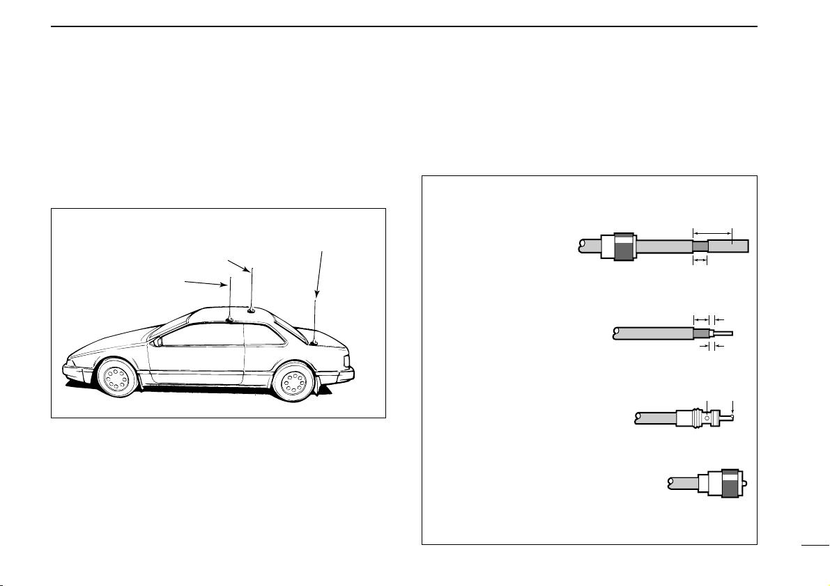
■ Antenna installation
30 mm
10 mm (soft solder)
10 mm
1–2 mm
solder solder
Soft
solder
Coupling ring
• PL-259 CONNECTOR
➀
➂
➃
➁
Slide the coupling ring
down. Strip the cable
jacket and soft solder.
Slide the connector
body on and solder it.
Screw the coupling
ring onto the connector body.
Strip the cable as
shown at right. Soft
solder the center conductor.
(10 mm ≈
3
⁄8 in)
INSTALLATION
2
D Antenna location
To obtain maximum performance from the transceiver, select
a high-quality antenna and mount it in a good location. A nonradial antenna should be used when using a magnetic mount.
Roof-mount antenna
(Drill a hole or use a magnetic mount.)
Gutter-mount antenna
D Antenna splitter
You can use a dual band antenna because a duplexer is installed in the transceiver. However, an external duplexer must
be connected when using a separate antenna for each band.
Trunk-mount
antenna
D Antenna connector
The antenna uses a PL-259 connector.
14
Page 20
3
Push [POWER] for 1 sec.
BAND
Indicates memory modeVFO mode is selected
VFO
SETTING A FREQUENCY
■ Preparation
D Turning power ON
Push [POWER] for 1 sec. to turn power ON.
D Main band
The IC-2710H can receive 144 MHz and 430(440) MHz band
signals simultaneously. Function access or frequency
changes affect the main band only. In addition, signals can
be transmitted on the main band only. Set the desired band
as the main band.
Push the desired band’s tuning dial to select the main band.
•“Q” indicates the main band.
Push [BAND] to toggle the main band selection
between the 144 and 430(440) MHz bands.
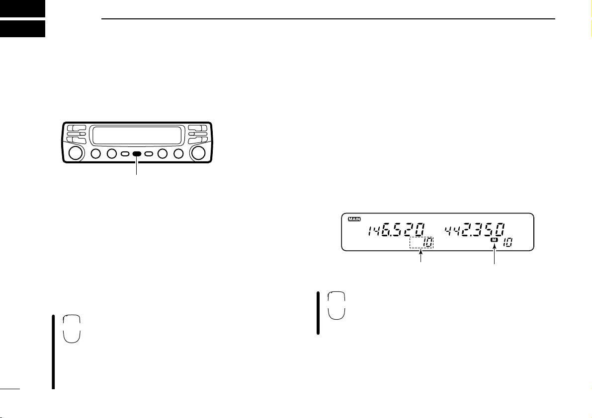
D VFO and memory modes
The transeiver has 2 normal operating modes: VFO mode
and memory mode. You can select VFO mode or memory
mode independently on each band.
Push the desired band’s [V/MHz] to select VFO mode when
the transceiver is not in VFO mode.
• If VFO mode is already selected, the digits below 100 kHz disappear. In this case, push [V/MHz] again (or push twice depending on
version).
Push [VFO] to select VFO mode.
• The microphone controls the main band only (or using
sub band access; p. 22). Push [BAND] to toggle the
main band, then push [VFO], if necessary.
15
Page 21
■ Lock functions
2 “L”s appear while the frequency lock function
is in use.
16 KEY LOCK
#
LOCK
SETTING A FREQUENCY
3
To prevent accidental frequency changes and unnecessary
function access, use the lock function. The transceiver has 2
different lock functions.
D Frequency lock
This function locks the tuning dials and switches electronically
and can be used together with the microphone lock function.
Push and hold [
nel readout to activate the function.
• To cancel the function, push and hold [
• [PTT], [BAND], [MONI], [MUTE], [VOL] and [SQL] can be used while
the frequency lock function is in use. Also, DTMF tones or DTMF
memory contents can be transmitted from the microphone.
(SET)L] until “L” appears in the memory chan-
(SET)L] until “L” disappears.
Push and hold [(VFO)LOCK] for 1 sec. to toggle
the function ON and OFF.
D Microphone keypad lock
This function locks the microphone keypad.
Push [FUNC] then [
the microphone keypad lock function ON and
OFF.
• [PTT] and the 7 keys on the upper half of the microphone can be used.
• All switches on the transceiver can be used.
• The keypad lock function is released when the
power is turned OFF then ON again.
A16 KEYLOCK] to toggle
16
Page 22
3
The display shows that the 1 MHz tuning step is
selected for the VHF band.
YZ
59
SETTING A FREQUENCY
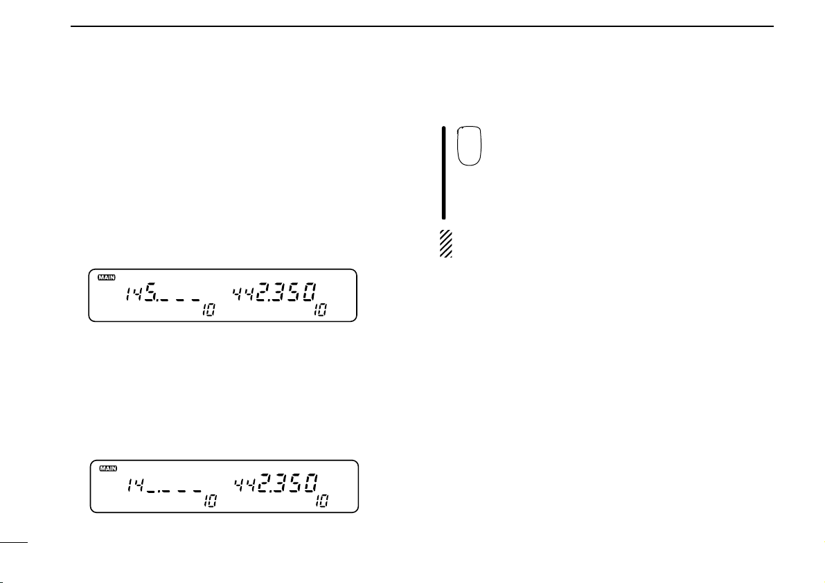
■ Using a tuning dial
➀ Rotate the desired band’s tuning dial to set the frequency.
• If VFO mode is not selected, push the same band’s [V/MHz] to
select VFO mode.
• Frequency changes according to the selected tuning steps.
(p. 18)
➁ For the 1 MHz frequency setting, rotate the same band’s
tuning dial after pushing [V/MHz].
• Pushing [V/MHz] for 1 sec. starts a scan function. If this happens,
push [V/MHz] again to stop the scan.
D 10 MHz steps
Some versions have 10 MHz tuning steps. For these versions
the [V/MHz] switch selects 10 MHz, 1 MHz then kHz steps in
sequence.
■ Using [Y]/[Z] switches
Push [Y] or [Z] to set the main band’s frequency.
• If VFO mode is not selected, push [VFO] to select it.
• Frequency changes according to the selected tuning
steps. (p. 18)
• Pushing [Y] or [Z] for more than 0.5 sec. activates a
scan. If this happens, push [Y] or [Z] again to stop it.
NOTE: 1 MHz steps cannot be used via the [Y]/[Z]
switches
17
Page 23
SETTING A FREQUENCY
25 kHz tuning step15 kHz tuning step
SET
B
3
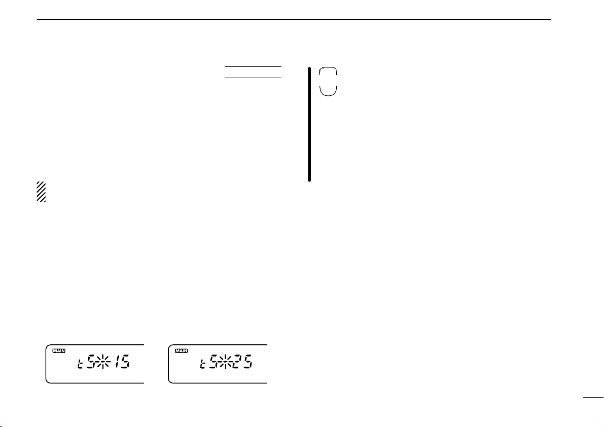
■ Tuning step selection
Tuning steps are the minimum frequency change increments
when you rotate the tuning dial or push the [Y] or [Z]
switches on the microphone. The following tuning steps are
available:
• 5 kHz • 10 kHz • 12.5 kHz • 15 kHz
• 20 kHz • 25 kHz • 30 kHz • 50 kHz
NOTE: For convenience, select a tuning step that
matches the frequency intervals of repeaters in your area.
USING
➀ Push the desired band’s tuning dial.
➁ Push the selected band’s [V/MHz] to select VFO mode if
another mode has been selected.
➂ Push the selected band’s [
until “tS” appears as shown below.
• Pushing [(SQL)MONI] reverses the order of selection.
• Cancel the DTMF memory or optional pager/code squelch in ad-
vance. (pgs. 49, 59, 62)
(VOL)SET] one or more times
➃ Rotate the selected band’s tuning dial to select the tuning
step.
➄ Push the selected band’s tuning dial to exit set mode.
SET MODE
Ä Push [BAND] to set the main band, if neces-
sary.
Å Push [VFO] to select VFO mode.
Ç Push [FSET] one or more times until “tS” ap-
pears as shown previously.
• Push [ENT] to reverse the order of selection.
• Cancel the DTMF memory or optional pager/code
squelch in advance. (pgs. 49, 59, 62)
É Push [Y] or [Z] to select the tuning step.
Ñ Push [CLR] to exit set mode.
18
Page 24
3
ENT
C
SETTING A FREQUENCY
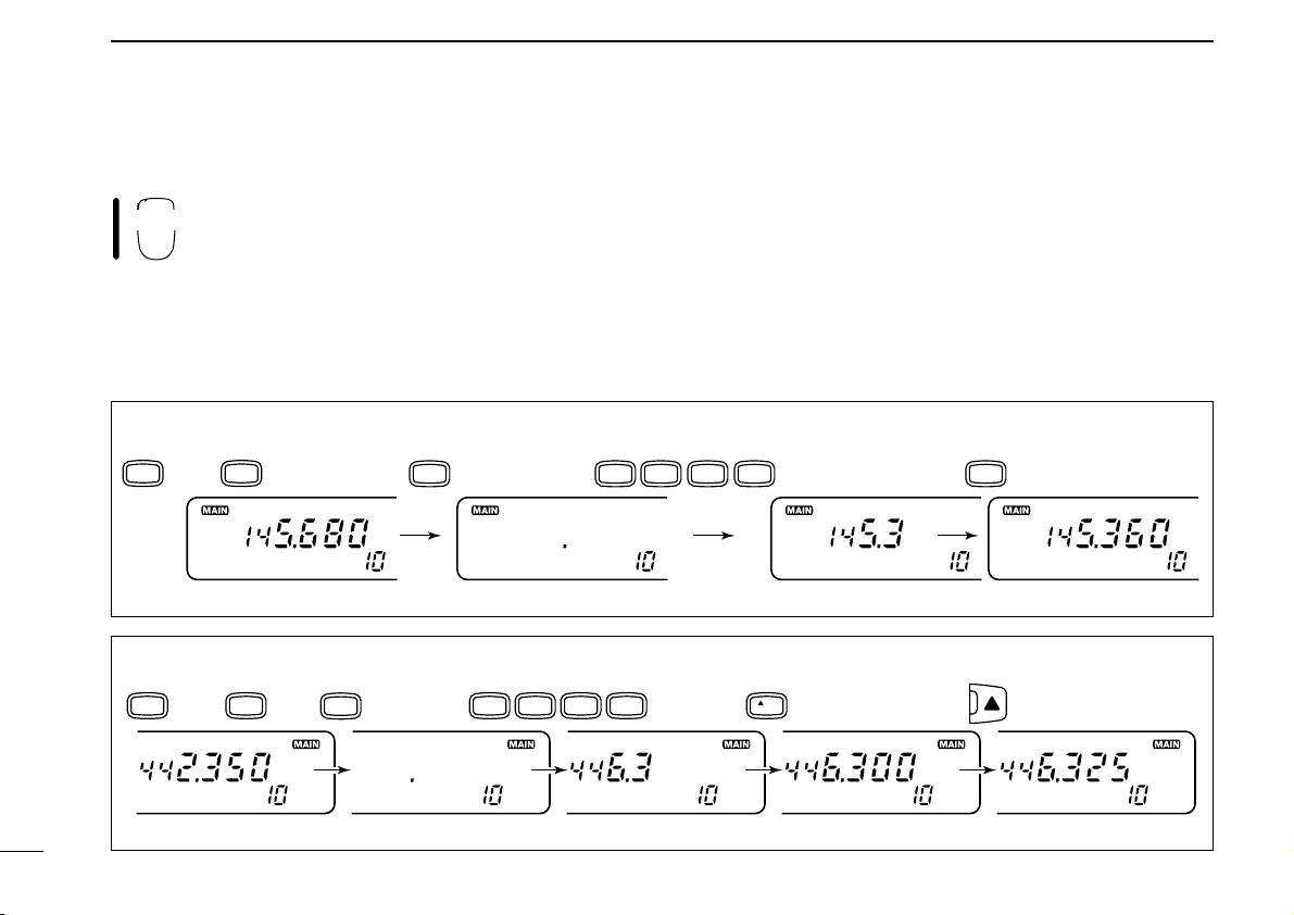
■ Using the keypad
The frequency can be directly set via numeral
keys on the microphone.
É Push 5 keys to input a frequency.
• When a digit is mistakenly input, push [ENT] to clear the input,
then input from the 1st digit.
• Pushing [CLR] clears input digits and retrieves the frequency.
Ñ Push [Y] or [Z] to make adjustments below the 10 kHz
Ä Push [BAND] to set the main band, if necessary.
digit, if desired.
Å Push [VFO] to select VFO mode.
Ç Push [ENT] to activate the keypad for digit input.
[EXAMPLE]: Setting the frequency to 145.360 MHz.
BAND
then
VFO
ENT
C
MONI4HIGH
1
[EXAMPLE]: Setting the frequency to 446.325 MHz. (When the 25 kHz tuning step is selected in UHF.)
PRIO
BAND
then
VFO
ENT
C
HIGH4HIGH
4
LOW
3
6
PRIO
MID
3
5
0
VOL
LOW
6
19
Page 25
BASIC OPERATION
BUSY
159
When receiving a signal on VHF.
BAND
VOL
VOL
Appears while setting volume Appears while setting squelch
BUSY
1 1
4
■ Receiving
The IC-2710H can receive 144 MHz and 430(440) MHz band
signals simultaneously.
➀ Push [POWER] for 1 sec. to turn power ON.
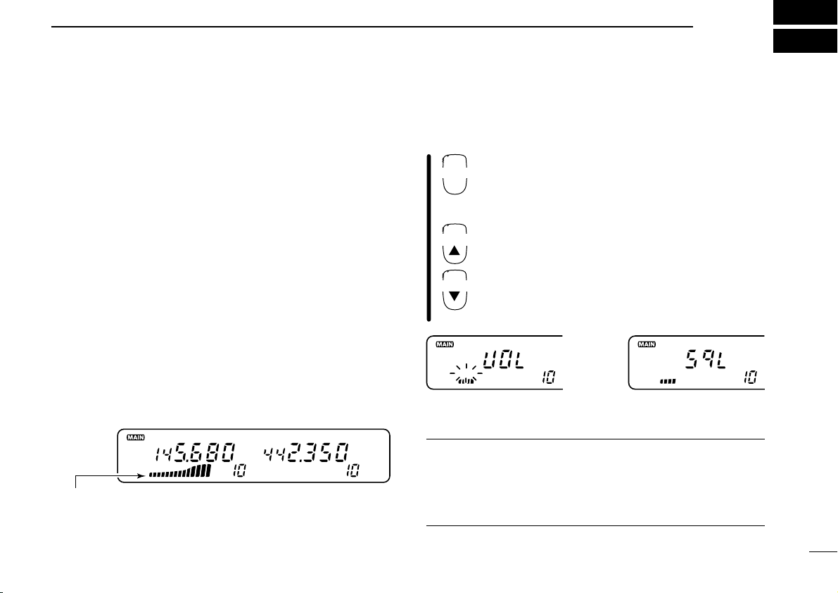
➁ Set the audio levels.
➥ Push [
➥ Rotate the [VOL] control to adjust the audio output level.
➥ Push [
➂ Set the squelch levels.
➥ Rotate [SQL] fully counterclockwise in advance.
➥ Rotate [SQL] clockwise until the noise just disappears.
➥ When interference is received, rotate [SQL] clockwise
➃ Set the operating frequency. (pgs. 15–19)
➄ When receiving a signal on the set frequency, squelch
opens and the transceiver emits audio.
•“BUSY” appears and the S/RF indicator shows the relative signal
strength on the received band.
(SQL)MONI] to open the squelch.
(SQL)MONI] again to close the squelch.
again for attenuator operation.
The volume and squelch levels can be adjusted via the microphone. However, levels return to the front panel setting
when power is turned OFF or a front panel control is adjusted.
Ä Push [POWER] on the transceiver for 1 sec. to
turn power ON.
Å Set the audio levels.
➥ Select the desired band.
➥ Push [➀MONI], then push [BZVOL] or
[IYVOL] to adjust the audio level.
➥ Push [➀MONI] again to close the squelch.
Ç Set the squelch level using [AZSQL] or
[HYSQL], if desired.
É Set the operating frequency. (pgs. 15–19)
✔ CONVENIENT
RF attenuator: The transceiver has an RF attenuator related
to the [SQL] setting. The attenuator is automatically activated
when [SQL] is rotated further than the 12 o’clock position.
Approx. 10 dB attenuation is obtained at full rotation.
20
Page 26
4
159
Appears when AM
mode is selected.
MONI
➀
MUTE
H
BASIC OPERATION
21
■ Monitor function
This function is used to listen to weak signals without disturbing the squelch setting or to open the desired band’s squelch
manually even when the optional mute functions such as tone
squelch, pager functions, etc., are in use.
Push the desired band’s [MONI] to open the desired band’s
squelch.
• Push [MONI] again to cancel the function.
• While duplex is ON for repeater operation, the transmitting fre-
quency can be monitored with [MONI].
Ä Push [BAND] to change bands, if necessary.
Å Push [➀MONI] to open the main band’s
squelch.
• Push [➀MONI] again to cancel the function.
■ Audio mute function
This function mutes both band’s audio signals
without disturbing the volume settings.
Ä Push [FUNC] then [HMUTE] to mute both band’s audio signals.
•“MUTE” appears for both bands.
Å Push [ECLR] (or any other key) to cancel the function.
•“MUTE” disappears.
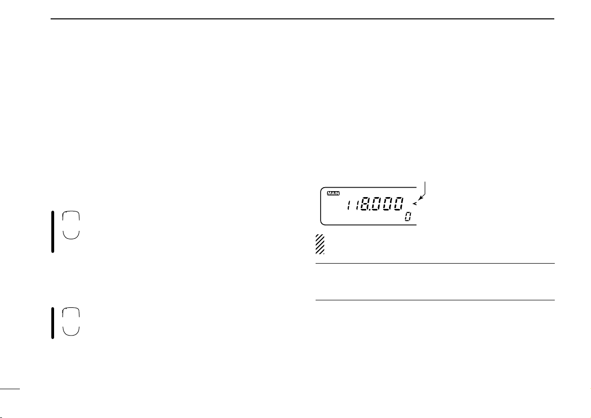
■ Avionics band receive
AM mode can be selected over the range of 118.000 to
135.995 MHz for reception of avionics-related broadcasts.
➥ Push and hold [
modes.
• Mode selection cannot be performed via the microphone.
NOTE: The avionics band can be selected in the left band
only, even when the para watch fuinction is in use.
✔ CONVENIENT
The tuning steps for the avionics band are available separately from those for other ranges.
(SQL)MONI] to toggle between AM and FM
(U.S.A. version only)
Page 27
BASIC OPERATION
“^” appears
BAND
4
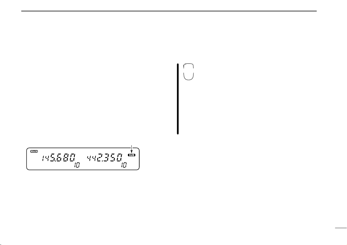
■ Sub band access
This function allows you to change sub band settings such as
duplex settings, especially useful from the microphone, during
transmission standby on the main band.
It’s easy to access the sub band and return to the main band
with the band switch.
➀ Push and hold the sub band’s tuning dial until “^” ap-
pears as shown below.
• If the [PTT] is pushed at this time, transmit is on the main band.
• If the main band’s tuning dial is mistakenly pushed and held, the
para-watch function is activated. In this case, push the main
band’s tuning dial for 1 sec. and repeat ➀ again. (p. 24)
➁ Activate functions such as duplex setting, subaudible
tones, etc.
➂ To exit sub band access, push the main band’s tuning dial.
• To switch from the sub band to the main band, push the sub
band’s tuning dial.
• Pushing and holding the sub band’s tuning dial until “^” dis-
appears also exits sub band access.
The sub band access function is also available from the microphone and is useful for setting the sub band’s frequency,
etc. during transmission standby on the main band.
Ä Push and hold [(BAND)SUB].
•“^” appears.
• If the [PTT] is pushed at this time, transmit is on the
main band.
Å Set the sub band’s operating frequency or acti-
vate functions.
Ç To exit sub band access, push and hold
[
•“^” disappears.
• To switch from the sub band to the main band (for
SUB] again.
(BAND)
transmitting), push [(BAND)
SUB] (momentarily).
22
Page 28

4
The display shows that the sub
band mute is turned ON and
the sub band busy beep is
turned OFF.
Common setting for each band
BASIC OPERATION
USING
■ Sub band mute/
INITIAL SET MODE
sub band busy beep
The sub band mute function automatically cuts out sub band
AF signals when both main and sub band signals are received simultaneously.
The sub band busy beep sounds when the sub band’s
squelch is closed to inform you that the sub band’s squelch
has been opened.
➀ While pushing [(VOL)SET L] (on the left side of the trans-
ceiver), push [POWER] to enter initial set mode.
➁ Push [SET] one or more times until “Sub” appears in the
display as shown above.
• Push [MONI] to reverse the order of selection.
➂ Rotate the main band’s tuning dial to set the condition.
DISPLAY SUB BAND MUTE BUSY BEEP
Sub-oF OFF OFF
Sub-oF S
Sub-on ON OFF
Sub-on S
OFF ON
ON ON
➃ Push [POWER] momentarily to exit initial set mode.
23
Page 29

BASIC OPERATION
Can be switched
between VHF and
UHF.
F-1
F-2
Receiving a VHF signal
4
■ Para-watch
The IC-2710H can simultaneously receive 2 signals on the
same band, 144 MHz or 430(440) MHz band, using the parawatch function.
[EXAMPLE]
➀ Push the desired band's tuning dial to assign the main
band.
➁ Push and hold the main band’s tuning dial until “-144-” or
“-430-” (or “-440-” for U.S.A. version) appears to change
the operating band.
➂ Repeat step ➁ again to cancel the function.
NOTE:
• Memory channels are common for the same band.
• Transmitting on the para-watch frequency is possible and
the transmission quality is the same as usual. However,
the opposite band’s audio is muted, even when both
bands are reversed.
The para-watch function cannot be activated from
the regular microphone keys. However, when the
tuning dial function is assigned to the user-programmable keys, [F-1] and [F-2], the para-watch
function can be activated via the microphone in
the same manner as described above.
24
Page 30

4
BASIC OPERATION
■ Transmitting
CAUTION: Transmitting without an antenna may dam-
age the transceiver.
NOTE:
➥ To prevent interference, listen on the frequency before
transmitting by pushing the main band’s [
the microphone’s [➀MONI].
➥ To prevent howling and sensitivity rejection, AVOID set-
ting the 430(440) MHz band frequency near a multiple
of the 144 MHz band frequency, e.g. setting for
145 MHz and 435 MHz.
➀ Push the desired band’s tuning dial to select the main band
for transmitting.
➁ Set the operating frequency. (pgs. 15–19)
• Select output power if desired. See section at right for details.
➂ Push and hold [PTT] to transmit.
•“$” appears.
• The S/RF indicator shows the output power selection.
• The operating frequency, etc. are automatically programmed into
a scratch pad memory. See p. 39 for details.
• One-touch PTT function is available. See p. 26 for details.
(SQL)MONI] or
➃ Speak into the microphone using your normal voice level.
• DO NOT hold the microphone too close to your mouth or speak
too loudly. This may distort the signal.
➄ Release [PTT] to return to receive.
■ Selecting the output power
The transceiver has 3 output power levels to suit your operating requirements. Lower output power during short-distance
communication may reduce interference to other stations and
reduces current consumption.
➀ Push the desired band’s tuning dial.
➁ Push [LOW] one or more times to select the desired out-
put power.
• The output power can be changed while transmitting.
POWER
SELECTION
HIGH 50 W 35 W
MID 10 W 10 W
LOW 5 W 5 W
S/RF INDICATOR
159
1515
LOW
11
LOW
VHF
UHF
25
Page 31

BASIC OPERATION
HIGH
4
MID
5
LOW
6
PTT-M
3
4
The microphone can select the desired output
power directly.
Ä Push [BAND] to select the desired band, if nec-
essary.
Å Push [➃HIGH] for high output power; [➄MID] for
middle output power; and [➅LOW] for low output power.
• The output power CANNOT be changed while transmitting.
■ Crossband full duplex
The transceiver can receive a signal on the sub band while
transmitting on the main band. Using this capability, crossband full duplex operation is possible. No special setting is
necessary for crossband full duplex operation.
➀ Set the desired transmit and receive frequencies on the
main and sub bands respectively for your transceiver.
(pgs. 15–19)
➁ Set the same frequencies, but set the receive band as the
main band for the other transceiver.
➂ Push and hold [PTT] to operate with full duplex.
• Transmitting and receiving activate simultaneously.
• One-touch PTT function (at right) and time-out timer are useful
for crossband full duplex operation. (p. 72)
■ One-touch PTT function
The PTT switch can be operated as a one-touch
PTT switch (each push toggles transmit/receive).
Using this function, you can transmit without pushing and holding the PTT switch.
To prevent accidental, continuous transmissions
with the one-touch PTT function, the transceiver
has a time-out timer. See p. 72 for details.
Ä Push [FUNC] then [➂PTT-M] to turn the one-touch PTT
function ON.
• The activity indicator lights green.
Å Push [PTT] to transmit and push again to receive.
• Two beeps sound when transmission is started and a long beep
sounds when returning to receive.
•“$” flashes while transmitting with the one-touch PTT func-
tion.
Ç Push [FUNC] then [➂PTT-M] to turn the one-touch PTT
function OFF.
• The activity indicator goes out.
26
Page 32

5
DUP
–
DUP
–
T
REPEATER OPERATION
■ Operation
➀ Push the desired band’s tuning dial.
➁ Set the receive frequency (repeater output frequency).
(pgs. 15–19)
➂ Push and hold [DUP] to select – duplex or push it for 1 sec.
again for + duplex.
•“DUP –” or “DUP” appears to indicate the transmit frequency for
minus shift or plus shift, respectively.
• When the auto repeater function is turned ON, (available for the
U.S.A. version only), steps ➁ and ➂ are not necessary. (p. 31)
➃ Push and hold [(DTMF)T] to turn ON the subaudible tone
encoder, according to repeater requirements.
• Refer to p. 29 for tone frequency settings.
• When the repeater requires a different tone system, see the page
at right.
➄ Push and hold [PTT] to transmit.
• The displayed frequency automatically changes to the transmit
frequency (repeater input frequency).
• The operating condition is automatically programmed into a
scratch pad memory. See p. 39 for details.
• If “oFF” appears, confirm the offset frequency. (p. 30)
➅ Release [PTT] to receive.
➆ Push the selected band’s [MONI] to check whether the
other station’s transmit signal can be directly received or
not.
➇ To return to simplex, push [DUP] for 1 sec., once or twice,
to clear the “DUP” indicator.
➈ To turn OFF the subaudible tone encoder, push and hold
[
(DTMF)T].
•“T” disappears.
• When the optional UT-104 is installed, push and hold [(DTMF)T]
an additional 2 times (for a total of 3 times).
27
Page 33

REPEATER OPERATION
DTMF S
TONE-1
TONE-2
DUP–
7
DUP+
8
SIMP
9
5
Ä Push [BAND] to select the desired band, if nec-
essary.
Å Set the receive frequency (repeater output fre-
quency). (pgs. 15–19)
Ç Push [➆DUP–] to select – duplex; push
[➇DUP+] for + duplex.
É Push [FUNC] then [➆TONE] to turn ON the sub-
audible tone encoder according to repeater requirements.
• Refer to p. 29 for tone frequency setting.
• When the repeater requires a different tone system,
see at right.
Ñ Push and hold [PTT] to transmit.
Ö Push and hold [➀MONI] to check whether the
other station’s signal can be directly received.
Ü Release [PTT] to receive.
á To return to simplex operation, push [➈SIMP].
à To turn OFF the subaudible tone encoder, push
[FUNC], then [GT-OFF].
D DTMF tones
Push [DTMF-S], then push the keys of the desired
DTMF digits.
• The function indicator lights green.
• 0–9, A–D, M(E) and #(F) are available.
• Cancel the DTMF memory encoder or optional pager/code
squelch function in advance. (pgs. 49, 59, 62)
• Push [DTMF-S] again to return the keypad to normal
function control.
• The transceiver has 8 DTMF memory channels for autopatch operation. See p. 49 for details.
D 1750 Hz tone
A 1750 Hz tone is required to access most
European repeaters. The microphone has 1750
Hz tone capability.
Ä Push [FUNC].
• The mode indicator lights orange.
Å Push [BTONE-1] to transmit a 1750 Hz tone call signal for
1 sec.; push and hold [
tone call signal for an arbitrary period.
• The mode indicator goes out automatically.
• The optional HM-90 also has 1750 Hz tone capability.
ITONE-2] to transmit a 1750 Hz
28
Page 34

29
159
T
Separate setting for each band
The display shows that an
88.5 Hz subaudible tone frequency is set.
SET
B
5
REPEATER OPERATION
■ Subaudible tones
USING
➀ Push the desired band’s tuning dial.
➁ Select the mode/channel you wish to set the subaudible
tone frequency to, such as VFO mode or memory/call
channel.
➂ Push [SET] one or more times until “T” appears and
flashes as shown above.
• Push [MONI] to reverse the order of selection.
• Cancel the DTMF memory encoder or optional pager/code
squelch function in advance. (pgs. 49, 59, 62)
➃ Rotate the selected band’s tuning dial to select and set the
desired frequency.
➄ Push the desired band’s tuning dial to exit set mode.
NOTE: The subaudible tone frequency can be set in a
memory channel temporarily. However, the set contents
are cleared once the memory/call mode is selected. To
store the tone frequency permanently, overwrite the channel information.
SET MODE
Ä Push [BAND] to select the desired band, if nec-
essary.
Å Set the mode/channel you wish to set the sub-
audible tone frequency to, such as VFO mode,
memory/call channel or scratch pad memory.
• The subaudible tone frequency is independently programmed into each mode or channel.
Ç Push [FSET] one or more times until “T” ap-
pears and flashes as shown at left.
• Pushing [GENT] reverses the order of selection.
• Cancel the DTMF memory encoder or optional
pager/code squelch function in advance. (pgs. 49,
59, 62)
É Push [Y] or [Z] to select and set the desired
frequency.
• Pushing and holding [Y] or [Z] changes the fre-
quency continuously.
Ñ Push [ECLR] to exit set mode.
• Subaudible tone frequency list (unit: Hz)
67.0
79.7 94.8 110.9 131.8 156.7 171.3 186.2
69.3 82.5 97.4 114.8 136.5 159.8 173.8 189.9
71.9 85.4 100.0 118.8 141.3 162.2 177.3 192.8
74.4 88.5 103.5 123.0 146.2 165.5 179.9 196.6
77.0
91.5 107.2 127.3 151.4 167.9 183.5 199.5
203.5
206.5
210.7
218.1
225.7
229.1
233.6
241.8
250.3
254.1
Page 35

■ Offset frequency
Separate setting for each band
The display shows that a 0.6
MHz (600 kHz) frequency is
set.
DUP
SET
B
USING
➀ Push the desired band’s tuning dial.
➁ Select the mode/channel you wish to set the offset fre-
quency to, such as VFO mode or memory/call channel.
• The offset frequency can be independently programmed into
each mode or channel.
➂ Push [SET] one or more times until “DUP” appears and
flashes as shown above.
• Pushing [MONI] reverses the order of selection.
• Cancel the DTMF memory encoder or optional pager/code
squelch function in advance. (pgs. 49, 59, 62)
➃ Rotate the selected band’s tuning dial to set the desired
frequency.
• Selectable step increment is the same as the preset tuning step.
(p. 18)
• Use the selected band’s [V/MHz] for quick MHz setting.
➄ Push the selected band’s tuning dial to exit set mode.
SET MODE
REPEATER OPERATION
5
Ä Push [BAND] to select the desired band, if nec-
essary.
Å Set the mode/channel you wish to set the offset
frequency to, such as VFO mode or
memory/call channel.
• The offset frequency can be independently programmed into each mode or channel.
Ç Push [FSET] one or more times until “DUP” ap-
pears and flashes as shown at left.
• Pushing [GENT] reverses the order of selection.
• Cancel the DTMF memory encoder or optional
pager/code squelch function in advance. (pgs. 49,
59, 62)
É Push [Y] or [Z] to select and set the desired
frequency.
• Selectable step increment is the same as the preset
tuning step. (p. 18)
• Pushing and holding [Y] or [Z] changes the fre-
quency continuously.
Ñ Push [ECLR] to exit set mode.
NOTE: The offset frequency can be set in a memory channel temporarily. However, the set contents are cleared
once the memory/call mode is selected. To store the offset
frequency permanently, overwrite the channel information.
30
Page 36

5
Duplex setting:
Tone encoder:
Automatic ON
Automatic OFF
Automatic ON
Automatic ON
DUP
T
DUP
REPEATER OPERATION
USING
■ Auto repeater
INITIAL SET MODE
(U.S.A. version only)
The U.S.A. version automatically activates the repeater settings (DUP or DUP– and tone encoder ON/OFF) when the
operating frequency falls within the general repeater output
frequency range and deactivates them when outside of the
range.
D Setting the auto repeater function ON/OFF
➀ Push [POWER] to turn power OFF.
➁ While pushing [(VOL)
enter initial set mode.
➂ Push [SET L] one or more times until the “rPt” display ap-
pears as shown below.
➃ Rotate the left-hand tuning dial to turn the auto repeater
function ON (“rPt-r1” or “rPt-r2”) or OFF (“rPt-oF”).
•“rPt-r1” and “rPt-r2” automatically set the duplex setting and du-
plex/tone encoder settings, respectively.
➄ Push [POWER] momentarily to exit initial set mode.
SET L] (left side), turn power ON to
D Frequency range and offset direction
FREQUENCY RANGE DUPLEX DIRECTION
145.200–145.495 MHz
146.610–146.995 MHz
147.000–147.395 MHz “DUP” appears
442.000–444.995 MHz “DUP” appears
447.000–449.995 MHz “DUP–” appears
“DUP–” appears
31
Page 37

MEMORY OPERATION
MR
Y/Z
MR
ENT
C
6
■ General description
The transceiver has 99 regular memory channels plus 6 scan
edge memory channels (3 pairs) on each band; each of these
can be individually programmed with the following data.
• Operating frequency (pgs. 15–19)
• Duplex direction (DUP or DUP–) and its offset frequency
(pgs. 27, 30)
• Subaudible tone encoder or tone squelch*
quency (pgs. 27, 29)
• Skip information*
*1An optional UT-104
2
*
Except for the scan edge memory channels.
2
(p. 45)
TONE SQUELCH UNIT
1
and its tone fre-
is necessary.
■ Memory channel selection
D Using a tuning dial
➀ Push the desired band’s [M/CALL] once or twice to display
“!”.
➁ Rotate the same band’s tuning dial to select the desired
memory channel.
• Only the programmed memory can be selected.
D Using [Y]/[Z] switches
Ä Push [BAND] to select the desired band, if nec-
essary.
Å Push [MR] to select memory mode.
Ç Push [Y] or [Z] several times to select the de-
sired memory channel.
• Pushing [Y]/[Z] more than 0.5 sec. activates a scan.
• If a scan is activated, push [Y] or [Z] again to stop it.
D Using the keypad
Ä Push [BAND] to select the desired band, if necessary.
Å Push [MR] to select memory mode.
Ç Push [GENT] to activate the keypad for numeral input.
É Push 2 appropriate digit keys to input a channel
number.
• When inputting non-programmed channel numbers
the previous memory channel appears.
• To select scan edge channels, “B” and “A” can be
used for A and b respectively.
32
Page 38

6
MEMORY OPERATION
■ Programming a memory channel
VFO mode settings, including the set mode contents such as
subaudible tone frequency, etc., are programmed into a memory channel.
➀ Set the desired frequency in VFO mode:
➥ Push the desired band’s [V/MHz] to select VFO mode.
➥ Set the frequency using the desired band’s tuning dial.
➥ Set other data (e.g. tone frequency, etc.) if required.
➁ Push [S.MW] momentarily.
•“!” and the memory channel number flashes.
➂ Rotate the tuning dial to select the memory channel to be
programmed.
• Memory channels not yet programmed are blank.
➃ Push [S.MW] for 1 sec. to program.
• 3 beeps may sound.
• Memory channel number automatically advances when continu-
ing to push [S.MW] after programming.
✔ CONVENIENT
Memory programming can be performed in versatile ways
e.g. memory channel to the same (or different) memory channel, memory channel to the call channel, etc.
[EXAMPLE]: Programming 145.870 MHz into memory channel 20 via the remote controller.
Push and Rotate for setting
Rotate
V/MHz
SCAN
Push
S.MW MW
freq., etc.
for 1 sec. and continue pushing
159159
Push
S.MW MW
momentarily
159
33
Page 39

MEMORY OPERATION
MW
■ Programming a memory channel via the microphone
6
Memory channel programming can be performed
via the microphone.
Ç Push [FUNC] then [EMW] momentarily.
É Select the memory channel to be programmed:
➥ Push [Y] or [Z] to select the memory channel (direct numeral
Ä Push [BAND] to select the desired band, if necessary.
Å Set the desired frequency in VFO mode:
➥ Push [VFO] to select VFO mode.
➥ Set the frequency using the keypad.
➥ Set other data (e.g. offset frequency, duplex direction, subaudi-
ble tone encoder ON/OFF and its frequency), if required.
input cannot be used).
Ñ Push [FUNC] then [EMW] for 1 sec. to program.
➥ 3 beeps may sound and the VFO contents (including the sub-
audible tone frequency, etc.) are programmed.
➥ Memory channel number advances when continuing to push
[MW] after programming.
[EXAMPLE]: Programming 145.870 MHz into memory channel 20 via the microphone.
MONI
Push , Push then
BAND VFO
ENT
PushPush for 1 sec. and
1
C
DUP+
8
then
FUNC A
HIGH
DUP
MID
5
4
7
159159
MW
CLR
continue pushing
FUNC
MW
CLR
A
159
momentarily
34
Page 40

DUP
–
T
DUP
–
T
S.MW MW
Push
+
for 1 sec.
MW
FUNC
A
CLR
MW
6
MEMORY OPERATION
■ Transferring memory
contents
This function transfers a memory channel’s contents into a VFO
(or another memory/call channel). This is useful when searching for signals around a memory channel frequency and for recalling the offset frequency, subaudible tone frequency, etc.
➀ Push the desired band’s tuning dial.
➁ Select the memory channel to be transferred:
➥ Select memory mode by pushing the selected band’s [M/CALL]
once or twice (“!” appears).
➥ Rotate the selected band’s tuning dial to select the memory
channel.
➂ Push [S.MW] momentarily, then rotate the tuning dial to se-
lect another memory channel to transfer.
• To transfer to the VFO, push and hold [
pushing momentarily.
➃ Push and hold [(S.MW)MW] to transfer when a momentary
push was used in the previous step.
(S.MW)MW] instead of
Ä Push [BAND] to select the desired band, if nec-
essary.
Å Select the memory channel to be transferred:
➥ Push [MR] to select memory mode.
➥ Push [Y] or [Z] to select the memory channel; or
push [GENT] then push the desired memory channel number (2 digits) to select the memory channel
directly.
Ç Push [FUNC] then [EMW] momentarily, then
push [Y] or [Z] to select another memory channel to transfer.
• To transfer to the VFO, push [FUNC] then push and
hold [EMW] instead of pushing momentarily.
É Push [FUNC] then [EMW] for 1 sec. to transfer
when a momentary push was used in the previous step.
35
Page 41

■ Memory clearing
159
Push Rotate
momentarily
again for 1 sec.
S.MW MW
Push
briefly, then push
S.MW MW
S.MW MW
Push
MEMORY OPERATION
6
Contents of programmed memories can be cleared (blanked),
if desired.
➀ Push [S.MW] momentarily.
➁ Select the memory channel to be cleared with the tuning
dial.
➂ Push [S.MW] briefly, then a second time for 1 sec.
• 3 beeps sound, then the frequency is cleared.
•“!” flashes continuously.
• Scan edges and call channel cannot be cleared.
➃ Push any switch to stop the flashing.
[EXAMPLE]: Clearing memory channel 20.
NOTE:
Be careful—the contents of cleared memories CANNOT
be recalled.
• Memory channel 0 and scan edge channels 1A/1b cannot be
cleared.
Memory clearing may not be performed from the
microphone.
36
Page 42

7
Large “C” shows the call
channel is selected.
Small “c” shows VFO mode
was selected from the call
channel.
CALL
MW
A
CALL CHANNEL OPERATION
■ Calling up a call channel
Each band has an independent call channel to store a mostoften-used frequency for quick recall.
➀ Push the desired band’s [M/CALL] once or twice to display
a large “C” in the memory channel readout.
• To transmit on the call channel, select the desired band as the
main band in advance.
➁ Push the same band’s [V/MHz] or [M/CALL] to exit the call
channel.
Ä Push [BAND] to select the desired band, if nec-
essary.
Å Push [(MR)CALL] for 1 sec. to select the call
channel.
■ Transferring call channel
contents
➀ Push the desired band’s tuning dial.
➁ Select the call channel by pushing the selected band’s
[M/CALL] once or twice.
• A large “C” appears.
➂ Push [S.MW] momentarily, then rotate the tuning dial to se-
lect another memory channel to transfer.
• To transfer to the VFO, push and hold [(S.MW)MW] instead of
pushing momentarily.
➃ Push and hold [(S.MW)MW] to transfer when a momentary
push was used in the previous step.
Ä Push [BAND] to select the desired band, if nec-
essary.
Å Push [(MR)CALL] for 1 sec. to select the call
channel.
Ç Push [FUNC], then [EMW] momentarily.
• To transfer to the VFO, push [FUNC] then [EMW] in-
stead of pushing [EMW] momentarily.
É Push [FUNC] then [EMW] for 1 sec. to transfer
when momentarily pushing [EMW] in step ➂.
37
Page 43

■ Programming a call channel
MW
A
BAND VFO
2
SCAN
5
MID
1
MONI
1
MONI
4
HIGH
C
ENT
MW
FUNC
A
CLR
CALL
MR
Call channel VFO mode then
for 1 sec.
for 1 sec.
Beep
Beep
Beep
CALL CHANNEL OPERATION
7
In addition to an operating frequency, duplex information and
subaudible tone information (tone encoder or tone squelch*
ON/OFF and its frequency) can be programmed into the call
channel.
*An optional UT-104 is necessary.
➀ Push the desired band’s tuning dial.
➁ Select the call channel by pushing the selected band’s
[M/CALL] once or twice. (A large “C” appears.)
➂ Set the desired frequency in VFO mode:
➥ Push [VFO] to select VFO mode.
➥ Set the frequency using the keypad.
➥ Set other data (e.g. offset frequency, duplex direction, subaudi-
ble tone encoder ON/OFF and its frequency), if required.
➃ Push [(S.MW)MW] for 1 sec. to program.
[EXAMPLE]: Programming 145.120 MHz into the VHF call channel via the microphone.
✔ CONVENIENT
The call channel can also be programmed from the VFO directly (similar to memory programming).
Ä Push [BAND] to select the desired band, if nec-
essary.
Å Push [(MR)CALL] for 1 sec. to select the call
channel.
Ç Set the desired frequency in VFO mode:
• Push [VFO] to select VFO mode.
• Set the desired frequency using the keypad.
• Set other data, if required.
É Push [FUNC] then [EMW] for 1 sec. to pro-
gram.
38
Page 44

8
Newest
Oldest
The oldest written frequency is cleared.
Order is changed if
transmitting on this
channel.
DUP
DUP
SCRATCH PAD MEMORY
■ What is a scratch pad
memory?
During VFO operation, the transceiver automatically memorizes operating frequency information, separate from regular
memory channels, when transmitting on a new frequency.
The 3 previously operated frequencies for each band can be
recalled.
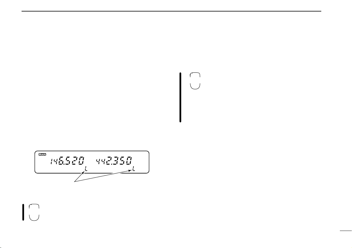
■ Calling up a scratch pad
memory
➀ Select the call channel by pushing the desired band’s
[M/CALL] once or twice. (A large “C” appears.)
• To transmit on the scratch pad memory, select the desired band
as the main band in advance.
➁ Rotate the selected band’s tuning dial to select a scratch
pad memory.
• Previously transmitted frequency and one of “L1–L3” appears.
• When first applying power or after CPU resetting, scratch pad
memories contain no data and therefore cannot be accessed.
➂ Push the selected band’s [V/MHz] or [M/CALL] to exit the
scratch pad memory.
• The 3rd scratch pad memory will be cleared when transmitting on a new frequency. If the transmit frequency is
already stored in a scratch pad memory, the scratch pad
memory is not cleared but the order is changed.
• When transmitting on a scratch pad memory, the scratch
pad memory becomes the 1st scratch pad memory and
the order is changed.
39
NOTE: When memory mode is selected, the frequency is
not programmed into a scratch pad.
Page 45

SCRATCH PAD MEMORY
CALL
Push for 1 sec.
then
S.MW MW
MW
FUNC
A
CLR
8
Ä Push [BAND] to select the desired band, if nec-
essary.
Å Push and hold [(MR)CALL] to select the call
channel.
Ç Push [Z] one or more times to select a duplex
scratch pad memory.
• Once entering a scratch pad memory, [Y] can also
be used for selection.
É Push [MR] or [VFO] to exit the scratch pad
memory.
■ Transferring scratch pad
memory contents
Transferring scratch pad memory contents to the VFO is done
similarly to transferring regular memory/call channel contents.
➀ Push the desired band’s tuning dial.
➁ Select the call channel by pushing the selected band’s
[M/CALL] once or twice.
• A large “C” appears.
➂ Rotate the selected band’s tuning dial to select the desired
scratch pad memory.
• One of “L1”–“L3” appears.
➃ Push [(S.MW)MW] momentarily.
• “” flashes to indicate VFO as the transferring channel.
➄ Rotate the tuning dial to select the desired memory chan-
nel if required.
➅ Push and hold [(S.MW)MW] to transfer.
Ä Push [BAND] to select the desired band, if nec-
MW
essary.
Å Push [(MR)CALL] for 1 sec. to select the call
channel.
Ç Push [Z] one or more times to select the de-
sired scratch pad memory.
É Push [FUNC] then [EMW] momentarily.
• “” flashes to indicate VFO as the transferring
channel.
Ñ Push [Y] or [Z] to select the desired memory
channel if required.
Ö Push [FUNC] then [EMW] for 1 sec. to transfer.
40
Page 46

9
FULL SCAN (p. 42)
Repeatedly scans all frequencies over the entire
band. Used as the simplest scan without any preliminary settings necessary.
PROGRAMMED SCAN
(p. 42)
Repeatedly scans between two userprogrammed frequencies.
Used for checking for frequencies within a specified range such as repeater output frequencies, etc.
3 pairs of scan edges are
available.
SCAN RESUME CONDITION
(p. 46)
5 resume conditions are
available: 3 timer scans,
pause scan and empty
scan. When receiving a
signal, pause scan pauses until the signal disappears; timer scans pause
for 5, 10 or 15 sec. Empty
pause scan pauses until a
signal appears.
MEMORY SCAN (p. 42)
Repeatedly scans memory channels except for skip
channels. Used for oftencalled channels and bypassing normally busy
channels such as repeater frequencies.
Band
edge
Band
edge
Scan
Jump
Band
edge
Band
edge
Scan
Jump
Scan edges
SKIP
SKIP
Mch 1 Mch 5
Mch 2 Mch 3 Mch 4
Mch 6
Mch 80
Mch 7
Pause
scan
Receiving
a signal
Timer
scan
Empty
pause
scan
Pausing
Pausing
2 sec.
2 sec.
SCAN OPERATION
■ Scan types
Scanning searches for transmitted signals automatically and
makes it easier to locate new stations for contact or listening
purposes.
Scanning with tone squelch:
When an optional tone squelch is in use, tone decode
scan acivates instead of the above scans. To activate the
41
Each band has 3 scan types and 5 resume conditions to suit
your needs. Scans on both bands can be operated separately
or simultaneously.
above scans with the tone squelch function, push and hold
[Y] or [Z] on the microphone.
Page 47

■ Scan start/stop
SCAN
2
SET
B
During full scan
Push to select full scan
and scan edge
pairs in sequence.
SET L
During programmed scan
Indicates scan edge channels.
• P1 stands for 1A/1b.
• P1 to P3 are available when
they are programmed.
During memory scan
D Pre-operation
• Common setting: scan resume condition. (p. 46)
• For programmed scan: program the scan edges. (p. 43)
• For memory scan: program 2 or more memory chan-
nels; set memory skip settings, if desired. (p. 45)
D Operation
➀ Push the desired band’s tuning dial.
➁ Select VFO mode for full/programmed scan; or memory
mode for memory scan with the selected band’s [V/MHz]
switch.
➂ Set the selected band’s squelch to the point where noise
is muted.
➃ Push [(V/MHz)SCAN] for 1 sec. to start the scan.
• When the optional tone squelch is in use, [(V/MHz)SCAN] starts
the tone scan.
• To change the scanning direction, rotate the selected band’s tun-
ing dial.
• The memory channel readout indicates the scan type as follows:
SCAN OPERATION
9
➄ To select the scan range while operating full/programmed
scan, push [SET] several times.
➅ To stop the scan, push [
(VMHz)SCAN].
Ä Push [BAND] to select the desired band, if nec-
essary.
Å Push [VFO] to select VFO mode for full/pro-
grammed scan; or push [MR] to select memory
mode for memory scan.
Ç Push [HYSQL] or [AZSQL] one or more times
to set the squelch just closed.
É Push [➂SCAN] to start the scan.
• [Y]/[Z] also start the scan when pushed and held.
Ñ To select the scan range while operating
full/programmed scan, push [SET] several
times.
Ö To stop the scan push [ECLR].
42
Page 48

9
SCAN OPERATION
■ Programming scan edges
Scan edges can be programmed in the same manner as
memory channels. Scan edges are programmed into pairs of
scan edge channels, 1A/1b to 3A/3b, in memory channels.
➀ Push the desired band’s tuning dial.
➁ Set the desired frequency in VFO mode:
➥ Push the selected band’s [V/MHz] to select VFO mode.
➥ Set the frequency using the selected band’s tuning dial.
➥ Set other data (e.g. offset frequency, etc.) if required.
➃ Rotate the tuning dial to select a scan edge channel (1A to
3A).
➄ Push [(S.MW)MW] for 1 sec. to program.
• 3 beeps may sound and the frequency is programmed.
• Scan edge 1b is automatically selected when continuing to push
[(S.MW)MW] after programming.
➅ To program a frequency for the other pair of scan edges,
1b to 3b, repeat steps ➃ and ➄.
• If the same frequency is programmed into both scan edges, programmed scan will not function.
➂ Push [S.MW] momentarily.
•“!” and the memory channel number flashes.
[EXAMPLE]: Programming 145.30 MHz and 145.80 MHz for the VHF scan edges 1A and 1b.
Push
VHF
tuning
dial.
then rotate
159
Push
S.MW MW
momentarily
continue pushing
S.MW MW
Rotate
159
Push
S.MW MW
and hold
43
Program 1b in the same manner.
Page 49

SCAN OPERATION
MW
A
9
■ Programming scan edges via
the microphone
➥ 3 beeps may sound and the VFO contents (including the sub-
audible tone frequency, etc.) are programmed.
➥ Memory channel number advances to the next scan edge chan-
nel (1b to 3b) when continuing to push [EMW] after program-
Ä Push [BAND] to select the desired band, if nec-
essary.
Å Set the desired frequency in VFO mode:
ming.
Ö To program a frequency for the other scan edge channel,
repeat steps Å
➥ Push [VFO] to select VFO mode.
➥ Set the frequency using the keypad.
Ç Push [FUNC] then [EMW] momentarily.
É Push [Y] or [Z] to select scan edge channels.
Ñ Push [FUNC] then [EMW] for 1 sec. to pro-
gram.
[EXAMPLE]: Programming 145.30 MHz and 145.80 MHz for the VHF scan edges 1A and 1b.
MONI
FUNC
PRIO
1
3
then
Push Push then
VFO
ENT
C
PushPush for 1 sec. and
HIGH
VOL
MID
5
4
Y
0
159159
MW
CLR
A
continue pushing
and Ñ.
FUNC
MW
CLR
A
159
momentarily
Program 1b
in the same
manner.
44
Page 50

9
SET
B
SCAN OPERATION
45
USING
■ Skip channel setting
SET MODE
The memory skip function speeds up scanning by checking
only desired memory channels. Set the memory channels to
be skipped or scanned as follows.
The display shows that VHF
memory channel 10 is set as
SKIP
Separate setting for each band
a skip channel.
➀ Push the desired band’s tuning dial.
➁ Select the memory channel to program or to cancel the
skip function on:
➥ Select memory mode by pushing the selected band’s [M/CALL]
once or twice.
➥ Rotate the selected band’s tuning dial to select the memory
channel.
➂ Push [SET] one or more times until “CHS” appears as
shown above.
• Pushing [MONI] reverses the order of selection.
➃ Rotate the selected band’s tuning dial to turn the skip func-
tion ON or OFF on the selected channel.
•“~” appears : The memory channel is skipped during
(CHS-on) memory scan.
•“~” disappears : The memory channel is scanned during
(CHS-OFF) memory scan.
➄ Push the selected band’s tuning dial to exit set mode.
NOTE: Scan edge memory channels cannot be specified
as skip channels, however, they are skipped during memory scan anyway.
Ä Push [BAND] to select the desired band, if nec-
essary.
Å Select the memory channel to program or to
cancel the skip function on:
➥ Select memory mode by pushing [MR].
➥ Push [Y] or [Z] to select a memory channel.
Ç Push [FSET] one or more times until “CHS” ap-
pears as shown at left.
• Pushing [GENT] reverses the order of selection
once entering set mode.
É Push [Y] or [Z] to set or cancel the skip infor-
mation.
• See item ➃ at left for skip indicator details.
Ñ Push [ECLR] to exit set mode.
Page 51

SCAN OPERATION
SET
B
9
■ Scan resume
USING
condition
The scan resume condition can be selected as timer, pause
or empty pause scan. The empty pause scan is useful for
finding unused frequencies. The resume condition is also
used for priority watch. (p. 47)
The display shows that the
scan resumes 15 sec. after it
stops.
Separate setting for each band
➀ Push the desired band’s tuning dial.
➁ Push [SET] one or more times until “SCt” or “SCP” appears
as shown above.
• Pushing [MONI] reverses the order of selection.
• Cancel the DTMF encoder or optional pager/code squelch in ad-
vance. (p. 49, 59, 62)
SET MODE
➂ Rotate the selected band’s tuning dial to set the desired
timer.
•“SCt-15” : Scan pauses 15 sec. while receiving a signal.
•“SCt-10” : Scan pauses 10 sec. while receiving a signal.
•“SCt-5” : Scan pauses 5 sec. while receiving a signal.
•“SCP-2” : Scan pauses until the signal disappears and then re-
sumes 2 sec. thereafter.
•“SCt-EP” : Scan pauses on a frequency that is not busy and re-
sumes 2 sec. after a signal appears.
➃ Push the selected band’s tuning dial to exit set mode.
Ä Push [BAND] to select the desired band, if nec-
essary.
Å Push [FSET] one or more times until “SCt” or
“SCP” appears as shown at left.
• Pushing [GENT] reverses the order of selection
once entering set mode.
• Cancel the DTMF memory encoder or pager/code
squelch in advance. (pgs. 49, 59, 62)
Ç Push [Y] or [Z] to select the scan resume con-
dition.
• See item ➂ above for scan resume condition details.
É Push [ECLR] to exit set mode.
46
Page 52

10
PRIORITY WATCH
■ Priority watch types
Priority watch checks for signals on a memory or call channel every 5 sec. while operating on a VFO frequency. The
transceiver has 3 priority watch types to suit your needs. You
can transmit on the VFO frequency while the priority watch
operates.
The watch resumes according to the selected scan resume
condition. See p. 46 for details.
NOTE:
• Priority watch cannot be started from a scratch pad
memory.
• The DTMF memory encoder or optional pager/code
squelch are turned OFF when priority watch starts.
• If the optional pocket beep function is activated, the
transceiver automatically selects the tone squelch function when priority watch starts.
• When “SCt-EP” is selected for the scan resume condition, the priority watch pauses on a no-signal channel.
(p. 46)
MEMORY CHANNEL
WATCH (p. 48)
5 sec.
125 msec.
VFO
frequency
Memory
channel
MEMORY SCAN WATCH
(p. 48)
SKIP
125 msec.
Mch 0
Mch 1
Mch 2
Mch 49
5 sec.
VFO
frequency
CALL CHANNEL WATCH
(p. 48)
5 sec.
125 msec.
VFO
frequency
Call
channel
While operating on a VFO
frequency, priority watch
checks for a signal on the
selected memory channel
every 5 sec.
• A memory channel with skip
information can be watched.
While operating on a VFO
frequency, priority watch
checks for signals on each
memory channel in sequence.
• The memory skip function and
memory area setting are useful to speed up the scan.
While operating on a VFO
frequency, priority watch
checks for a signal on the
call channel every 5 sec.
47
Page 53

■ Priority watch operation
PRIO
While pausing on the
memory or call channel, “PRIO” flashes.
PRIO
3
PRIORITY WATCH
10
➀ Push the desired band’s tuning dial.
➁ Select VFO mode; then, set an operating frequency.
➂ Set the watching channel(s).
For memory channel watch:
Select the desired memory channel.
For memory scan watch:
Select memory mode; then, push [
to start memory scan.
For call channel watch:
Select the call channel by pushing the selected band’s
[M/CALL] once or twice.
➃ Push the selected band’s [
the watch.
• The transceiver checks the memory or call channel frequency
every 5 sec.
• The watch resumes according to the selected scan resume condition. (p. 46)
• While the watch is pausing, pushing the selected band’s
[M/CALL] resumes the watch manually.
(M/CALL)PRIO] for 1 sec. to start
(V/MHz)SCAN] for 1 sec.
➄ Push the selected band’s [M/CALL] while the display
shows the VFO frequency to stop the watch.
Ä Push [BAND] to select the desired band, if nec-
essary.
Å Select VFO mode; then, set an operating fre-
quency.
Ç Set the watching channel(s).
For memory channel watch:
Push [MR] then [Y] or [Z] to select the desired
memory channel.
For memory scan watch:
Push [MR] then [➁SCAN] to start the memory
scan.
For call channel watch:
Push and hold [
channel.
(MR)CALL] to select the call
É Push [➂PRIO] to start the watch.
• The transceiver checks the memory or call channel
frequency every 5 sec.
• The watch resumes according to the selected scan
resume condition. (p. 46)
• To resume the watch manually while pausing, push
[➂PRIO] or [ECLR].
Ñ To stop the watch, push [ECLR] once (or twice
while watch pauses).
48
Page 54

11
“d” appears in place of
the 100 MHz digit.
DTMF MEMORY ENCODER
■ Programming a DTMF code
DTMF codes are used for autopatching, accessing repeaters,
controlling other equipment, etc. The transceiver has 8 DTMF
memory channels (d1– d8) for storage of often-used DTMF
codes of up to 16 digits.
NOTE: DTMF memory channels are commonly used for
both bands. Therefore, programming each band is not
necessary.
➀ Push [DTMF] once and “d” appears in place of the main
band’s 100 MHz digit as shown below.
➁ Push [(VOL)SET] to enter the programming condition.
➂ Rotate the main band’s tuning dial to select the desired
channel.
➃ Push [SET] or [MONI] to select the cursor.
➄ Rotate the main band’s dial to select a digit.
•“E” stands for “M” and “F” stands for “#.”
➅ Repeat steps ➃ and ➄ until the last digit is entered.
• The S/RF indicator shows the digit group. The indication increases every 6 digits.
• Select “–” to clear the remaining digits when programming over a
49
previously used memory channel.
➆ Push the main band’s tuning dial to exit the programming
condition.
■ Clearing the DTMF memory
contents
➀ Push [DTMF] to turn the DTMF memory encoder ON.
➁ Push [SET] to enter the programming condition.
➂ Rotate the main band’s tuning dial to select the desired
channel.
➃ Push [SET L] (for VHF display) or [MONI] (for UHF display)
to activate the 1st digit.
➄ Rotate the main band’s tuning dial to select “–” and clear
the memory channel contents.
➅ Push the main band’s tuning dial to exit the programming
condition.
Page 55

DTMF MEMORY ENCODER
DTMF
6
Push
8
DUP+
5
MID
5
MID
4
HIGH
4
HIGH
A
CLR
then
FUNC
DTMF
6
LOW
B
SET
B
SET
2
SCAN
3
PRIO
BAND
■ Programming a DTMF code via the microphone
11
DTMF codes can be directly programmed via the
keypad on the microphone. The contents can be
overwritten, but cannot be cleared via the microphone. See the page at left for clearing the contents.
Ä Push [FUNC] then [➅DTMF] to turn the DTMF memory
function ON.
•“d” appears in place of the 100 MHz digit.
Å Push [FSET] to enter the programming condition.
Ç Push [Y] or [Z] to select the desired channel.
[EXAMPLE]: Programming “5428AB453” into DTMF memory channel “d4.”
É Push the desired digit keys.
• When the first digit is input, previous memory contents are
cleared automatically.
•“E” stands for “M” and “F” stands for “#.”
• Push [Y] then [Z], and repeat this step when making a mistake.
• The S/RF indicator shows the digit group. The indication in-
creases every 6 digits.
Ñ Push the [BAND] to exit the programming condition.
• The [ECLR] key cannot be used to exit. If pushed, “A” is input,
and the previously programmed data is erased. Reprogram again
in such a case.
50
Page 56

11
DTMF
6
DTMF-S
DTMF MEMORY ENCODER
■ Transmitting a DTMF code
D Using the DTMF memory function
(automatic transmission)
The selected DTMF code is transmitted at each push of the
PTT switch when the DTMF memory encoder is turned ON.
➀ Push [DTMF] to turn the DTMF memory encoder ON.
•“d” appears in place of the main band’s 100 MHz digit.
➁ Push [SET] to enter the programming condition.
➂ Rotate the main band’s tuning dial to select the desired
DTMF memory channel.
➃ Push [PTT] to transmit the selected DTMF code.
• At each push of [PTT], the selected DTMF code is transmitted.
• The speaker emits the DTMF tones sent.
➄ Push [DTMF] to cancel the function.
•“d” disappears.
• When an optional UT-49 is installed, push [DTMF] several times until
a number appears for the 100 MHz digit and “REMO” disappears.
Ä Push [FUNC] then [➅DTMF] to turn the DTMF
memory encoder ON.
•“d” appears in place of the main band’s 100 MHz
digit.
Å Push [FSET] to enter the programming condi-
tion.
Ç Push [Y] or [Z] to select the desired channel.
É Push [PTT] to transmit the selected DTMF code.
• At each push of [PTT], the selected DTMF code is transmitted.
Ñ Push [ECLR] to cancel the function.
D Transmitting a DTMF memory channel directly
Ä Push [FUNC] then [➅DTMF] to turn the DTMF
memory encoder ON.
•“d” appears in place of the main band’s 100 MHz
digit.
Å Push [DTMF-S], then push the desired DTMF
channel number.
•“1” to “8” are available for channel numbers.
Ç Push [DTMF-S] again to deactivate the DTMF
setting.
É Push [ECLR] to turn the DTMF memory en-
coder OFF.
• When the DTMF memory encoder is turned ON continuously, each push of the PTT transmits the previously selected DTMF code.
51
Page 57

■ DTMF speed
Common setting for each band
The display shows the fastest DTMF speed is selected.
USING
INITIAL SET MODE
DTMF MEMORY ENCODER
11
The rate at which DTMF memories send individual DTMF
characters can be set to accommodate operating needs. This
setting does not affect an optional pager or code squelch operation.
➀ Push [POWER] to turn power OFF.
➁ While pushing [(VOL)SET L] (left side), push [POWER] for
1 sec. to turn power ON and enter initial set mode.
➂ Push [(VOL)SET L] or [(SQL)MONI] to select the “dtd” dis-
play as shown above.
➃ Rotate the main band’s tuning dial to select the desired
speed as shown in the table at right.
➄ Push [POWER] momentarily to exit initial set mode.
DISPLAY INTERVAL SPEED
dtd-1 100 msec. 5.0 cps
dtd-2 200 msec. 2.5 cps
dtd-3 300 msec. 1.6 cps
dtd-5 500 msec. 1.0 cps
cps=
characters/second
52
Page 58

12
T SQLS
8
T-OFF
C
POCKET BEEP AND TONE SQUELCH
■Pocket beep operation
optional UT-104
53
This function uses subaudible tones for calling and can be
used as a “common pager” to inform you that someone has
called while you were away from the transceiver.
To operate the pocket beep function, an optional UT-104 is
necessary. See p. 65 for installation details.
D Waiting for a call from a specific station
➀ Push the desired band’s tuning dial.
➁ Set the operating frequency.
➂ Program the subaudible tone frequency in set mode.
• See p. 29 for programming details.
➃ Push [(DTMF)T] for 1 sec., 2 times to indicate “T SQLS”
in the function display.
• Turn OFF the pager or code squelch to activate the pocket beep.
(pgs. 59, 62) The pocket beep cannot be used in combination
with the pager or code squelch.
➄ When a signal with the correct tone is received, the trans-
ceiver emits beep tones and flashes “S”.
• Beep tones sound for 30 sec. To stop the beeps manually, push
the tuning dial (or any key).
•“S” flashes coninuously until step ➅ or ➆.
• When receiving another call while “S” is flashing, no beeps sound.
➅ Push [PTT] to answer.
• Tone squelch is automatically selected when transmitting.
➆ Push [(DTMF)T] for 1 sec. once or twice to cancel the function.
Ä Push [BAND] to select the desired band, if nec-
essary.
Å Set the operating frequency.
Ç Program the subaudible tone frequency in set
mode.
• See p. 29 for programming details.
É Push [FUNC] then [➇T SQLS] to turn the
pocket beep ON.
• Turn OFF the pager or code squelch to activate the
pocket beep. (pgs. 59, 62) The pocket beep cannot
be used with the pager or code squelch.
Ñ When a signal with the correct tone is received,
the transceiver emits beep tones for 30 sec.
and flashes “S.”
Ö Push [PTT] to answer or push [ECLR] to stop
the beeps and flashing.
• Tone squelch is automatically selected.
• Pushing [FUNC] then [➈TSQL] also selects the tone
squelch.
Ü To cancel the function, push [FUNC] then
[GT-OFF].
D Waiting for a call from a specific station
A subaudible tone matched with the stations frequency is
necessary. Use the tone squelch on the next page or a subaudible tone encoder (p. 29).
Page 59

■ Tone squelch operation
T SQL
9
T-OFF
C
POCKET BEEP AND TONE SQUELCH
12
The tone squelch opens only when receiving a signal with the
same pre-programmed subaudible tone. This function can be
activated on both bands with separate tone frequencies simultaneously. To operate the tone squelch function, an optional UT-104 is necessary.
➀ Push the desired band’s tuning dial.
➁ Set the operating frequency.
➂ Program the subaudible tone frequency in set mode.
• See p. 29 for programming details.
➃ Push [(DTMF)
pears in the function display.
• The pager or code squelch can be used together with the tone
squelch. (p. 62)
T] for 1 sec., several times until “T SQL” ap-
➄ When the received signal includes the correct tone, the
squelch opens and the signal can be heard.
• When the received signal includes an incorrect tone, the squelch
does not open. However, the S/RF indicator shows the received
signal strength.
• To open the accessed band’s squelch manually, push the ac-
cessed band’s [MONI].
➅ Operate the transceiver in the normal way (push [PTT] to
transmit; release [PTT] to receive).
➆ To cancel the tone squelch, push [(DTMF)T] for 1 sec.
•“T SQL” disappears from the function display.
Ä Push [BAND] to select the desired band, if nec-
essary.
Å Set the operating frequency.
Ç Program the subaudible tone frequency in set
mode.
• See p. 29 for programming details.
É Push [FUNC] then [➈T SQL] to turn the tone
squelch ON.
• The pager or code squelch can be used with the
tone squelch. (p. 62)
Ñ When the received signal includes the correct
tone, the squelch opens and the signal can be
heard.
• When the received signal includes and incorrect
tone, the squelch does not open. However, the S/RF
indicator shows the received signal strength.
• To open the accessed band’s squelch manually,
push [➀MONI].
Ö Operate the transceiver in the normal way
(push [PTT] to transmit; release [PTT] to receive).
Ü To cancel the tone squelch, push [FUNC] then
[GT-OFF].
54
Page 60

12
DUP
–
T SQL
T SQL
9
POCKET BEEP AND TONE SQUELCH
■ Tone scan
55
By monitoring a signal that is being transmitted on a repeater
input frequency, you can determine the tone frequency necessary to open a repeater.
An optional UT-104 is required to activate the tone scan.
➀ Push the desired band’s tuning dial.
➁ Set the desired frequency to be checked for a tone fre-
quency e.g. repeater input frequency.
➂ Push [(DTMF)T] for 1 sec., 3 times to display “T SQL.”
➃ Push [(V/MHz)SCAN] for 1 sec. to start the tone scan.
• To change the scanning direction, rotate the selected band’s tun-
ing dial.
➄ When the tone frequency is matched, the squelch opens
and the tone frequency is programmed into the selected
mode such as VFO, memory/call channel or scratch pad
memory.
➅ Push [(V/MHz)SCAN] to stop the scan.
➆ Push [(DTMF)T] for 1 sec. to deactivate the tone squelch or
twice to activate the tone encoder with the detected tone
frequency.
Ä Push [BAND] to select the desired band, if nec-
essary.
Å Set the desired frequency to be checked for a
tone frequency e.g. repeater input frequency.
Ç Push [FUNC] then [➈T SQL] to turn the tone
squelch ON.
É Push [➁SCAN] to start the tone scan.
Ñ When the tone frequency is matched, the
squelch opens and the tone frequency is programmed into the selected mode such as VFO,
memory/call channel or scratch pad memory.
Ö Push [ECLR] to stop the scan.
Ü Push [FUNC] then [GT-OFF] to deactivate the
tone squelch or push [FUNC] then [➆TONE] to
activate the tone encoder with the detected
tone frequency.
NOTE: The decoded tone frequency is programmed temporarily when a memory or call channel is selected.
However, this will be cleared when overwriting the memory/call channel.
Page 61

No answer back
➂ Answer
back
No pager
111
333/555
222/555
111/555
➀
➀
➀
➀
➁
beep
beep
optional UT-49
■ Pager function
PAGER AND CODE SQUELCH
13
The pager functions can be used only when an optional
UT-49 is installed. This function uses DTMF codes for paging
and can be used as a “message pager” to inform you of a
caller’s identity even if you leave the transceiver temporarily
unattended.
Personal calls and group calls are available with the pager
function. Personal calls use the receiving parties’ ID code for
other stations in the party know that you called.
Group calls use the group code for calling. All station displays
show the group code and all stations know that someone in
your group called.
To use the pager function in your group, all stations need the
pager function.
calling. The receiving parties’ display shows your ID code and
PAGER SIMULATION: Personal call PAGER SIMULATION: Group call
No answer back
No pager
➀
➀
➀
555
➂ Answer
back
beep
➁
beep
333/555
➂
222/555
➂
➀
111/555
beep
➁
beep
beep
➁
beep
56
Page 62

13
SKIP
SKIP
PAGER AND CODE SQUELCH
■ Code channels
D Before programming
The pager and code squelch functions require ID codes and a
group code. These codes are 3-digit DTMF codes and must
be written in the code channels before operation. The transceiver has separate code channels for each band.
D Code channel assignment
ID OR
GROUP CODE
Your ID code 0 “Receive accept” only.
Other parties’
ID code
Group code One of 1–5
Memory space* P “Receive inhibit” only.
* Code channel P automatically memorizes an ID code when receiv-
ing a pager call. The contents in channel P cannot be changed
manually.
CODE CHANNEL
NUMBER
1–5
“RECEIVE ACCEPT”
OR “RECEIVE INHIBIT”
“Receive inhibit” should
be programmed in each
channel.
“Receive accept” must be
programmed.
RECEIVE ACCEPT AND INHIBIT
Code channels 1–5 can store the transmit codes for personal calls to other individuals and the group codes for
group calls.
The group codes should be programmed as “receive accept” (“” disappears) to receive all calls from group
members.
If transmit codes are not programmed as “receive inhibit,”
the transceiver accepts calls directed to other individuals
and your answer back may confuse other members in your
group—this is not a selective calling system. Therefore,
transmit codes should be programmed as “receive inhibit”
(“” appears) so the transceiver rejects calls directed to
other individuals.
57
Page 63

PAGER AND CODE SQUELCH
SKIP
159
The display shows that
VHF code channel 0
(your ID code) is programmed for 248.
SKIP
SET
B
13
■ Code programming
➀ Push the desired band’s tuning dial.
• Each band has separate code channels.
➁ Push [DTMF] 2 times to turn the pager function ON.
•“P” appears in place of the 100 MHz digit.
➂ Push [(VOL)SET] to select the code channel setting display.
➃ Rotate the selected band’s tuning dial to select the desired
code channel, 0–5.
• Code channel P cannot be used for programming.
➄ Push [(SQL)MONI] or [(VOL)SET] to select the digit to be
programmed.
➅ Rotate the selected band’s tuning dial to set the digit.
➆ Repeat ➄ and ➅ until the last digit is programmed.
➇ Push [DTMF] to set the code channel for “receive inhibit”
or “receive accept.”
• When “receive inhibit” is set, “” appears.
• Code channel 0 cannot be set as “receive inhibit.”
• See p. 57 for “receive inhibit” or “receive accept” details.
➈ Push the selected band’s tuning dial to exit the setting dis-
play.
Ä Push [BAND] to select the desired band, if nec-
essary.
• Each band has separate code channels.
Å Push [FUNC] then [➃PGR] to turn the pager
function ON.
•“P” appears in place of the 100 MHz digit.
Ç Push [FSET] to select the code channel setting
display.
É Push [Y] or [Z] to select and set the desired
code channel, 0–5.
• Code channel P cannot be used for programming.
Ñ Push the numeral keys to enter the desired
3-digit code.
• Digits are automatically stored once the 3rd digit has
been entered.
Ö Push [FSET] to set the code channel for “re-
ceive inhibit” or “receive accept.”
• When “receive inhibit” is set, “” appears.
• Code channel 0 cannot be set as “receive inhibit.”
• See p. 57 for “receive inhibit” or “receive accept” de-
tails.
Ü Push [ECLR] to exit the setting display.
58
Page 64

13
PGR
4
PAGER AND CODE SQUELCH
■ Pager operation
59
D Calling a specific station
➀ Push the desired band’s tuning dial.
➁ Set the operating frequency.
➂ Push [DTMF] 2 times to turn the pager function ON.
•“P” appears in place of the 100 MHz digit.
• An optional tone squelch can be used together with the pager
function, although the pocket beep cannot be used. (p. 54)
➃ Select the desired code channel:
➥ Push [SET].
➥ Rotate the selected band’s tuning dial to select the code chan-
nel.
➥ Push the selected band’s tuning dial to exit the setting display.
➄ Push [PTT] to transmit the pager code.
➅ Wait for an answer back.
• When the transceiver receives an answer back code, the function display shows the other parties’ ID or group code and beeps.
(p. 60)
➆ After confirming a connection, push the selected band’s
tuning dial to display the operating frequency.
• DO NOT push numeral keys on the microphone while a 3-digit
code is indicated, or code channel contents are changed.
➇ Push [DTMF] once to select code squelch or 2 times (or 3
times for U.S.A. version) to select the non-selective calling
system.
Ä Push [BAND] to select the desired band, if nec-
essary.
Å Set the operating frequency.
Ç Push [FUNC] then push [➃PGR] to turn the
pager function ON.
•“P” appears in place of the 100 MHz digit.
• An optional tone squelch can be used together with
the pager function. (p. 54)
É Select the desired code channel:
➥ Push [FSET].
➥ Push [Y] or [Z] to select the code channel.
➥ Push [ECLR] to exit the setting display.
Ñ Push [PTT] to transmit the pager code.
Ö Wait for an answer back.
• When the transceiver receives an answer back
code, the function display shows the other parties’
ID or group code and beeps. (p. 60)
Ü After confirming a connection, push [ECLR] to
display the operating frequency.
• DO NOT push numeral keys on the microphone
while a 3-digit code is indicated, or code channel
contents are changed.
á Push [FUNC] then [➄C SQL] to select code
squelch or push [ECLR] to select the non-selective calling system.
• Pushing [FUNC] then [FD-OFF] also selects the
non-selective calling system.
Page 65

PAGER AND CODE SQUELCH
PGR
4
13
D Waiting for a call from a specific station
➀ Push the desired band’s tuning dial.
➁ Set the operating frequency.
➂ Push [DTMF] to turn the pager function ON.
•“P” appears in place of the 100 MHz digit.
• An optional tone squelch can be used together with the pager
function, although the pocket beep cannot be used. (p. 54)
➃ Wait for a call.
• When receiving a call, the other parties’ ID or group code ap-
pears; “S” and the channel number blink as shown on the next
page.
• DO NOT push numeral keys on the microphone while a 3-digit
code is indicated, or code channel contents are changed.
➄ Push [PTT] to send an answer back call and display the
operating frequency.
➅ Push [DTMF] once to select the code squelch system or 2
times (or 3 times for U.S.A. version) to select the non-selective calling system.
Ä Push [BAND] to select the desired band, if nec-
essary.
Å Set the operating frequency.
Ç Push [FUNC] then [➃PGR] to turn the pager
function ON.
•“P” appears in place of the 100 MHz digit.
• An optional tone squelch can be used together with
the pager function. (p. 54)
É Wait for a call.
• When receiving a call, the other parties’ ID or group
code appears; “S” and the channel number blink
as shown on the next page.
• DO NOT push numeral keys on the microphone
while a 3-digit code is indicated, or code channel
contents are changed.
Ñ Push [PTT] to send an answer back call and
display the operating frequency.
Ö Push [FUNC] then [➄C SQL] to select code
squelch or push [ECLR] to select the non-selective calling system.
• Pushing [FUNC] then [FD-OFF] also selects the
non-selective calling system.
60
Page 66

13
PAGER AND CODE SQUELCH
PERSONAL CALLS
This display appears when
you are called with your ID
code and the calling station’s
ID code is 263.
GROUP CALLS
This display appears when
you are called with the group
code, 123, and 123 has been
programmed into code channel 5.
ERROR INFORMATION
When the transceiver receives
an incomplete signal, “E” appears.
159
159
159
SKIP
SKIP
■ Code squelch function
The code squelch function can be used only when an optional
UT-49 is installed.
Code squelch operation provides communication with silent
standby since you only receive calls from stations which know
your ID or group code. To use the code squelch function in
your group, all stations need the code squelch function.
The code squelch function transmits a 3-digit code prior to
voice transmission in order to open the receiving station’s
code squelch.
CODE SQUELCH SIMULATION:
000/555
61
“E” appears
000
111/555
111
No code squelch
function
Page 67

■ Code squelch operation
“C” appears in place
of the 100 MHz digit.
C SQL
5
CLR
A
PAGER AND CODE SQUELCH
13
➀ Push the desired band’s tuning dial.
➁ Set the operating frequency.
➂ Push [DTMF] 3 times to turn the code squelch ON.
•“C” appears in place of the 100 MHz digit as shown below.
• An optional tone squelch can be used together with the code
squelch, although the pocket beep cannot be used. (p. 54)
➃ Select the desired code channel:
➥ Push [SET].
➥ Rotate the selected band’s tuning dial to select the code chan-
nel.
➥ Push the selected band’s tuning dial to exit the setting display.
➄ Operate the transceiver in the normal way (push [PTT] to
transmit; release [PTT] to receive).
• Prior to voice transmission, a 3-digit transmit code is sent each
time [PTT] is pushed in order to open the receiving station’s code
squelch.
➅ To cancel the code squelch, push [DTMF] once (or 2 times
for the U.S.A. version).
• The display shows the operating frequency.
Ä Push [BAND] to select the desired band, if nec-
essary.
Å Set the operating frequency.
Ç Push [FUNC] then [➄C SQL] to turn the code
squelch ON.
•“C” appears in place of the 100 MHz digit.
• An optional tone squelch can be used together with
the code squelch. (p. 54)
É Select the desired code channel:
➥ Push [FSET].
➥ Push [Y] or [Z] to select the code channel.
➥ Push [ECLR] to exit the setting display.
Ñ Operate the transceiver in the normal way
(push [PTT] to transmit; release [PTT] to receive).
• Prior to voice transmission, a 3-digit transmit code
is sent each time [PTT] is pushed in order to open
the receiving station’s code squelch.
Ö To cancel the code squelch push [ECLR].
• Pushing [FUNC] then [FD-OFF] also cancels the
code squelch.
62
Page 68

14
Password
(if programmed)
(or
“F”)
(or
“E”)
Command
(See examples at right)
B # B
M
EXTERNAL DTMF REMOTE (U.S.A. version only)
optional UT-49
When installing the optional UT-49
U.S.A. version can be remotely controlled using DTMF signals on the sub band. To operate external DTMF remote, a
144 MHz or 430(440) MHz transceiver with a DTMF encoder
is required.
DTMF DECODER UNIT
➀ Set the sub band frequency to receive a control signal
(DTMF code).
• The optional tone squelch function can be used for the sub band
to increase remote control reliability. (p. 54)
➁ Program a 3-digit password into the sub band’s code chan-
nel 5, if desired. (p. 58)
• The initial value of code channel 5 is “000; receive accept.” If you
do not require the password, set the channel as “receive inhibit.”
➂ Select the main band by pushing a tuning dial, then set the
desired frequency for operation.
➃ Push [DTMF] one or more times until “REMO” appears to
select standby for the remote control.
➄ Set the operating frequency of the controller transceiver
equal to the sub band frequency of the IC-2710H.
• Make sure a tone frequency is set when using the optional tone
squelch function with the IC-2710H.
• The external DTMF remote does not accept a control signal on
the main band frequency.
63
, the
➅ From the controller transceiver, transmit the DTMF code as
follows:
•“#” and “REMO” flash while receiving a control signal.
➆ To cancel standby for the remote control, push [DTMF].
•“REMO” disappears.
• Pushing [FUNC] then [FD-OFF] also cancels standby for the re-
mote control
Page 69

EXTERNAL DTMF REMOTE
[ENT] 100
MHz10MHz
1 MHz 100
kHz
10 kHz
3D14 4
VFO
mode
144.750 MHz
CALL MR VFO CLR
[ENT]
2 digits
2D15
Memory
mode
Memory channel 15
Scratch pad
memory 2
7
1 2 3 A
HIGH
4 5 6 B
LOW1
7 8 9 C
UP ENTDOWN
M
0 # D
5
[EXAMPLE]
DTMF KEYPAD
[DOWN] [DOWN]
1
Call
channel
MM
Password
(if programmed)
(or “F”) [ENT] (or “E”)(UP)
Frequency setting
B123 3# D 1458
VFO
mode
#
M
0 B
Note for the [ENT] key
[EXAMPLE]: Setting the operating frequency to 145.8125 MHz (when the VHF tuning step is 12.5 kHz).
• When the entered frequency is outside of the frequency coverage, the input
digits will be cleared.
• To adjust the frequency less than 10 kHz or to select a scan edge memory
channel (1A, 1b), use the [UP] or [DOWN] key.
14
64
Page 70

65
Bottom cover
fig. 1
fig. 2
fig. 3
Openings
UT-104
UT-49
15
OPTIONAL UNIT INSTALLATION
■ Optional unit installation
There are 2 optional internal units available.
DTMF DECODER UNIT
UT-49
The following functions are added when the UT-49 is installed:
• Pager function
• Code squelch
• External DTMF remote function (U.S.A. version only)
UT-104
The following functions are added when the UT-104 is installed:
• Tone decode scan
• Tone squelch (CTCSS tone decoder)
• Pocket beep function
For installation of either unit, proceed as follows:
TONE SQUELCH UNIT
➀ Turn power OFF then disconnect the DC power cable.
➁ Set the transceiver upside down, then unscrew the one
screw from the bottom cover.
➂ Open the bottom cover. (fig. 1)
• Use a flat head screwdriver or similar flat instrument to lever the
bottom cover open via the 2 openings towards the rear.
RWARNING! NEVER attempt to open the cover using your
nails, this may result in injury.
➃ Plug the unit into the proper position as specified in the
above illustration. (fig. 2, 3)
➄ Replace the bottom cover and tighten the screw.
Page 71

LOCK
AFC AFC-OFF PTT-M MW
PGR
CALL
123A
456B
MR VFO CLR
C-SQL DTMF D-OFF
HIGH MID LOW SET
The diagram shows that
the wireless remote control function is turned
ON.
Dip switch
1 2 3 4
ON
OFF
optional EX-1759 and HM-90
IC-2710H EX-1759
BC-96
Use the
microphone’s
cable
HM-90
WIRELESS OPERATION
16
■ Connection
Wireless remote control is available when the following options are used:
• HM-90
• EX-1759
The BC-96
for use with the HM-90, since the HM-90’s internal battery requires charging.
D Recommended connection
WIRELESS MICROPHONE
INFRARED RECEIVER
MICROPHONE HOLDER
is additionally recommended
■ HM-90
WIRELESS MICROPHONE
The HM-90’s internal battery should be charged when the microphone is not being held.
Charging period: 1.5 hrs. with timer
(or 8 hrs. when battery is exhausted)
Operating period: 12 hrs (Operation : standby= 1 : 4)
D Charging method
Choose a method from one of the following:
• Connect the cable from the HM-90 to the EX-1759.
• Connect the BC-96 and EX-1759; then put the HM-90 into
the BC-96 (refer to the diagram at left).
• Use the CP-1
CIGARETTE LIGHTER CABLE
to connect the
BC-96 and cigarette lighter socket.
D Turning the wireless remote ON/OFF
When you use the HM-90 as a wired microphone, turn OFF
the wireless remote control circuit if desired.
66
Page 72

16
(When using BC-96
with external DC)
(When using the mic
connector for mic
charging.)
The installation clip can be oriented in 1 of 4 ways.
EX-1759
WIRELESS OPERATION
■ EX-1759 installation
The EX-1759
ent purposes depending on the HM-90 charger. This is because the EX-1759 has both an infrared receiver and a
microphone connector which contains microphone charging
capabilities.
• When using the BC-96 with external DC input
Attach the EX-1759 to a suitable location for receiving infrared signals, e.g. sunvisor, etc.
• When using the connector for a microphone charger
Attach the EX-1759 to a suitable location for receiving infrared signals and where it can be connected to a cable, e.g.
the console, etc.
NOTE: DO NOT attach the EX-1759 where it will be subject to direct sunlight as it cannot detect infrared signals
under such conditions.
67
INFRARED RECEIVER
can be installed for 2 differ-
• Optional infrared sub receiver
An optional EX-1513
increase the remote control reliablility and extend the controllable area. Connect the EX-1513 to the inside connector of
the EX-1759.
NOTE: The supplied microphone, HM-98, can be connected and used with the EX-1759, however, the optional
wireless microphone cannot be used in such a case.
INFRARED SUB RECEIVER
is available to
Page 73

WIRELESS OPERATION
BAND
SELECT
MONI
REMOTE CONTROL MICROPHONE
VOLSQL
LOCK
JAPAN
AFC AFC-OFF PTT-M MW
PGR
CALL
123A
456B
M
0#D
MR VFO CLR
C-SQL DTMF D-OFF
SCAN
MONI
FUNC
DTMF
KEY
DTMF
MEMO
MUTE SQL ENT
789C
DUP– DUP+SIMP SPCH
PRIO REAR LOCK DEMO
TONE
HIGH MID LOW SET
T-SQLS T-SQL T-OFF
➓
➊
➋
➌
➍
➎
➏
➐
➑
➒
Front and side panels Rear panel
16
■ HM-90 switches
➊ PTT SWITCH
➥ Push and hold to transmit; release to receive.
➥ Toggles between transmitting and receiving while the
one-touch PTT function is in use.
➋ BAND SWITCHES [BAND SELECT Y,Z]
➥ Select the desired band as the main band.
➥ Activate the para-watch function when pushed and held
when the main band is selected.
➥ Activate the sub band access function after pushing
[FUNC] on the rear panel.
➌ MONITOR SWITCH [MONI]
Toggles between opening and closing the accessed band’s
squelch.
➍ SQUELCH LEVEL UP/DOWN SWITCHES
[YSQL], [ZSQL]
Vary the accessed band’s squelch threshold point for noise
mute.
➎ FREQUENCY UP/DOWN SWITCHES [UP], [DN]
➥ Push either switch to change the operating frequency,
memory channel, set mode contents, etc.
➥ Push and hold either switch to start scanning.
➏ ACTIVITY INDICATOR [UP], [DN]
Lights red while a key is pushed; lights green while the
one-touch PTT function is in use.
➐ AUDIO VOLUME UP/DOWN SWITCHES
[YVOL], [ZVOL]
Adjust the accessed band’s audio level.
➑ MODE INDICATOR
Indicates the microphone condition.
• Lights red when [FUNC] is pushed.
• Lights green when [DTMF KEY] is pushed.
• Lights orange when [DTMF MEMO] is pushed.
➒ LOCK SWITCH [LOCK]
Locks all switches and keys on the microphone except for
the PTT switch.
➓ KEYPAD
Used for controlling the transceiver, transmitting a DTMF
memory channel, etc.
68
Page 74

16
FUNC
DTMF
MEMO
DTMF
KEY
D
ENT
DEMO
WIRELESS OPERATION
D Keypad
KEY FUNCTION
AFC
CALL
AFC-OFF
MR
PTT-M
VFO
PGR
HIGH
C-SQL
MID
DTMF
LOW
TONE
DUP–
T-SQLS
DUP
T-SQL
SIMP
PRIO
MUTE
Calls up a call channel. No secondary function.
1
Selects memory mode. No secondary function.
2
Selects VFO mode. Turns the one-touch PTT function ON
3
Selects high output power. Turns the optional pager function ON.
4
Selects mid output power. Turns the optional code squelch function
5
Selects low output power. Turns the DTMF memory function ON.
6
Selects – duplex. Turns the subaudible tone encoder ON.
7
Selects + duplex. Turns the optional pocket beep function
+
8
Selects simplex. Turns the optional tone squelch function
9
Mutes both bands’ audio signals. Starts and stops a priority watch.
0
SECONDARY FUNCTION (After )
and OFF.
ON.
ON.
ON.
OTHER FUNCTIONS
• After :
Input the appropriate digit
for frequency or memory
channel selection.
• After :
Transmit the appropriate
DTMF code.
• After :
Transmit the appropriate
DTMF memory contents.
[1] to [8] can be used for
DTMF memory.
69
Page 75

WIRELESS OPERATION
FUNC
DTMF
KEY
16
KEY FUNCTION
MW
CLR
Clears a digit before entry.
A
Cancels the scan, priority watch, pager,
code squelch or DTMF memory function.
D-OFF
SET
T-OFF
SPCH
Enters set mode and advances the set
B
mode selection order.
Decreases the set mode selection order
after entering set mode.
C
NOTE:
The IC-2710H has no voice synthesizer
function.
DEMO
ENT
SCAN
MONI
M
REAR LOCK
SQL
Sets the keypad for numeral input. Enters and exits demonstration mode.
D
Opens and closes the accessed band’s
squelch.
Selects 1 of the 4 preset squelch levels. Locks all the keys on the microphone key-
#
SECONDARY FUNCTION (After )
Writes the VFO contents into the memory
channel or call channel.
Advances the memory channel number
when continuously pushed after programming is completed.
Turns the pager, code squelch, DTMF
memory or DTMF remote function OFF.
Turns the subaudible tone encoder, or optional pocket beep/tone squelch OFF.
Starts and stops scanning.
Starts tone scan while an optional tone
squelch is in use.
pad.
OTHER FUNCTIONS
• After :
Transmit the appropriate
DTMF code.
[BMONI]
Transmits a 1750 Hz tone
call signal for 1 sec.
[ASQL]
Transmits a 1750 Hz tone
call signal while pushing.
70
Page 76

16
The display shows the microphone address is set to 1.
WIRELESS OPERATION
■ Microphone
address
The transceiver has 8 possible microphone addresses to help
prevent interference from other HM-90
PHONES
dip switch to the same value as follows.
D Microphone address
➀ Push [POWER] to turn power
➁ While pushing [(VOL)SET L],
➂ Push [SET] a few times to se-
➃ Rotate the left-hand tuning dial to set the microphone ad-
➄ Turn power OFF to exit initial set mode.
71
. Set both the microphone address and microphone
NOTE: When the supplied microphone is connected, the
transceiver rejects control signals from the HM-90 even
when the microphone address is matched.
OFF.
turn power ON to enter initial
set mode.
lect the “Adr” display as
shown at right.
dress to 0–7 or to turn the microphone control OFF.
• When “Adr-oF” is selected, the transceiver rejects all control signals from the HM-90.
USING
INITIAL SET MODE
WIRELESS MICRO
D Microphone dip switch
➀ Remove the switch cover from the microphone rear panel.
➁ Set the microphone dip switch and the microphone ad-
-
dress to the same value as shown below.
➂ Replace the switch cover.
MICROPHONE
ADDRESS
Adr-0 OFF OFF OFF
Adr-1 (default) ON OFF OFF
Adr-2 OFF ON OFF
Adr-3 ON ON OFF
Adr-4 OFF OFF ON
Adr-5 ON OFF ON
Adr-6 OFF ON ON
Adr-7 ON ON ON
Dip switch
ON
OFF
(S1)
1 2 3
S1–1 S1–2 S1–3
AFC AFC-OFF PTT-M MW
CALL
123A
PGR
HIGH MID LOW SET
456B
DIP SWITCH
LOCK
MR VFO CLR
C-SQL DTMF D-OFF
Switch cover
Page 77

OTHER FUNCTIONS
The display shows that beep
tones are turned ON.
17
USING
■ Beep tones on/off
You can select silent operation by turning beep tones OFF or
you can select to have confirmation beeps sound at the push
of a switch by turning beep tones ON.
INITIAL SET MODE
➀ Push power to turn power OFF.
➁ While pushing [(VOL)
set mode.
➂ Push [(VOL)
• Pushing [(SQL)MONI] reverses the order of selection.
SET L] one or more times until “bEP” appears.
SET L], turn power ON to enter initial
➃ Rotate the left-hand tuning dial to select the condition.
•“bEP-oF”: Beep tones are turned OFF.
•“bEP-on”: Beep tones are turned ON.
➄ Push [POWER] momentarily to exit initial set mode.
USING
■ Time-out timer
To prevent accidental prolonged transmission with the onetouch PTT function, etc., the transceiver has a time-out timer.
This timer cuts a transmission OFF after 3, 5, 15 or 30 min. of
continuous transmission. This timer can be cancelled (default).
Approx. 10 sec. before the time-out timer passes, the transceiver emits a beep tone as a warning.
TOT
The display shows that the 5
min. timer is selected.
The display shows that the
time-out timer is cancelled.
INITIAL SET MODE
➀ Push [POWER] to turn power OFF.
➁ While pushing [(VOL)SET L], turn power ON to enter initial
set mode.
➂ Push [(VOL)SET L] one or more times until “tot” appears.
• Pushing [
(SQL)MONI] reverses the order of selection.
➃ Rotate the left-hand tuning dial to select the desired time-
out time or turn the timer OFF (“oF”).
➄ Push [POWER] momentarily to exit initial set mode.
72
Page 78

17
The display shows that the
30 min. timer is selected.
AO
The display shows that the
cooling fan is set for automatic operation.
The display shows that the
cooling fan is set for continuous operation.
OTHER FUNCTIONS
USING
■ Auto power-off
The auto power-off function conveniently turns the transceiver
power OFF after a preset time in which no operations are performed. In this way, when you forget to turn the power OFF,
the transceiver automatically turns itself OFF, thereby conserving battery power.
The time can be set to 30 min., 1 hr., 2 hr. or turned OFF. The
selected time is retained even when the transceiver is turned
OFF via the auto power-off function. To cancel the function,
select “oF” in step ➃ below.
INITIAL SET MODE
➀ Push [POWER] to turn power
OFF.
➁ While pushing [(VOL)SET L],
turn power ON to enter initial
set mode.
➂ Push [(VOL)SET L] one or
more times until “PoF” appears.
• Pushing [
(SQL)MONI] reverses the order of selection.
➃ Rotate the left-hand tuning dial to select the desired auto
power-off time or turn the timer OFF (“oF”).
•“AO” appears when an auto power-off time is set.
➄ Push [POWER] momentarily to exit initial set mode.
USING
■ Cooling fan
INITIAL SET MODE
setting
The transceiver has a heatsink and cooling fan to radiate
heat. The cooling fan automatically turns ON while transmitting and remains ON for 2 min. after transmitting. The cooling fan can be activated continuously, if desired.
➀ Push power to turn power OFF.
➁ While pushing [(VOL)SET L], turn power ON to enter initial
set mode.
➂ Push [(VOL)SET L] one or more times until “FAn” appears.
• Pushing [
➃ Rotate the left-hand tuning dial to set the cooling fan to au-
tomatic (“At”) or continuous (“on”).
➄ Push [POWER] momentarily to exit initial set mode.
(SQL)MONI] reverses the order of selection.
73
Page 79

OTHER FUNCTIONS
9
17
■ Microphone [F-1]/[F-2] keys
Switches on the transceiver’s front panel can be assigned to
the microphone’s [F-1] and [F-2] keys.
➀ Turn power OFF.
➁ While pushing the desired switch on the transceiver and
[F-1] or [F-2] on the microphone, turn power ON.
• The switches’ function is programmed into the key ([F-1] or [F-2]).
• Default setting
The following functions are assigned to the [F-1]/[F-2] keys
when first applying power or after CPU resetting:
[F-1]: VHF band tuning dial switch
[F-2]: UHF band tuning dial switch
■ Display dimmer setting
Adjust the intensity intensity to suit lighting conditions and
personal preference.
➀ Push and hold [VOL(SET)D] (right side) until “d-1”–“d4” ap-
pears as shown below.
➁ Rotate the tuning dial (right side) to set the desired inten-
sity.
• Intensity can be set from “d1” (dark) to “d4” (bright).
➂ Push [VOL(SET)
D] to return to normal operation.
■ Demonstration display
A demonstration function is available at power ON. This function gives you a quick visual introduction to the function display indicators.
➀ While pushing either tuning dial, push [POWER] to turn
power ON.
• The transceiver cycles through a visual tour of the function display indicators.
➁ Push any switch to exit demonstration mode and enter the
normal operating condition temporarily.
NOTE: The transceiver automatically returns to demonstration mode after 2 min. in which no operations are performed. To deactivate the demonstration display
permanently, perform step ➀ again.
74
Page 80

18
MAINTENANCE
■ Troubleshooting
PROBLEM POSSIBLE CAUSE SOLUTION REF.
No power comes on. • Power connector has a poor contact.
No sound comes from the
speaker.
Sub band signals are not audible.
Sensitivity is low and only
strong signals are audible.
No contact possible with another station.
Repeater cannot be accessed.
Frequency cannot be set.
• Polarity of the power connection is reversed.
• Blown fuse.
• Volume level is too low.
• The squelch level is set too tight.
• An optional selective call or squelch function is
activated such as tone squelch, pocket beep,
pager or code squelch.
• The sub band mute function is activated. • Turn the function OFF. p. 23
• Antenna feedline or the antenna connector sol-
der has a poor contact or is short circuited.
• The transceiver is set to semi-duplex.
• The other station is using code or tone squelch.
• Wrong offset frequency is programmed.
• Wrong subaudible tone frequency is pro-
grammed.
• The frequency lock function is activated.
• Priority watch is paused on the watching fre-
quency.
If your transceiver seems to be malfunctioning, please check
the following points before sending it to a service center.
• Check the connector pins.
• Reconnect the power cable observing the proper
polarity. Replace the fuse, if damaged.
• Check the cause, then replace the fuse.
• Rotate [VOL] clockwise.
• Set the squelch level to the threshold.
• Turn the appropriate function OFF.
• Check, and if necessary, replace the feedline or
solder the antenna connector again.
• Set to simplex.
• Turn ON the optional code squelch (UT-49) or
optional tone squelch (UT-104 ).
• Correct the offset frequency.
• Correct the subaudible tone frequency.
• Turn the function OFF.
• Push [(M/CALL)PRIO] to resume the watch.
—
pgs.
13, 77
p. 77
p. 20
p. 20
pgs.
53, 54,
59, 62
p. 14
p. 28
pgs.
62, 54
p. 30
p. 29
p. 16
p. 48
75
Page 81

PROBLEM POSSIBLE CAUSE SOLUTION REF.
Frequency cannot be set via
microphone.
• The frequency lock function is activated.
• The microphone keypad lock function is acti-
vated.
• Priority watch is paused on the watching frequency.
MAINTENANCE
• Push and hold [
frequency lock function.
• Push [FUNC], then [A16KEY LOCK] to deacti-
vate the microphone keypad lock function.
• Push the selected band’s [(M/CALL)PRIO] to re-
sume the watch.
(VFO)
LOCK] to deactivate the
18
p. 16
p. 16
p. 48
Some memory channels
cannot be selected via the
microphone keypad.
Scan does not operate. • Squelch is open.
Transmission is automatically cut off.
Transmission continues
even when the PTT is released.
The function display shows
erroneous information.
• The input channel number has not yet been programmed.
• The selected scan edge memory channels (e.g.
1 A and 1b) have the same frequencies (for programmed scan).
• Only 1 memory channel is programmed or other
channels are set as skip channels.
• Priority watch is activated.
• Time-out timer is activated. • Set the timer to OFF. p. 72
• One-touch PTT function is activated. • Turn the function OFF. p. 26
• The CPU is malfunctioning. • Reset the transceiver.
• Rotate the tuning dial to check whether the
channel has been programmed or not.
• Set the squelch to the threshold point.
• Reset the scan edges.
• Program other memory channels or cancel the
memory skip function in the desired channels.
• Turn the function OFF.
p. 32
p. 20
p. 43
pgs.
33, 45
p. 48
p. 77
76
Page 82

18
MAINTENANCE
77
■ Fuse replacement
If the fuse blows or the transceiver stops functioning, find the
source of the problem if possible, and replace the damaged
fuse with a new, rated one (FGB 20 A) as shown in the diagram below.
■ Partial resetting
If you want to initialize the operating conditions without clearing the memory contents, etc., a partial reset function is available for the transceiver. The partial reset can be performed
independently for each band.
While pushing either left or right, or both [V/MHz] switches,
turn power ON to partially reset the transceiver.
➧ Initialized settings: VFO frequency, SET mode settings.
➧ Retained settings: Memory channels, call channels, offset
freq. in memory/call, DTMF memory,
pager and code squelch settings, initial
SET mode settings.
■ Resetting the transceiver
The function display may occasionally display erroneous information, (e.g. when first applying power). This may be
caused externally by static electricity or other factors.
If this problem occurs, turn power OFF. After waiting a few
seconds, turn power ON again. If the problem persists, perform the following procedure.
Partial resetting is alternatively available. See previous section for details.
CAUTION: Resetting the transceiver CLEARS all
memory information, and initializes all values in the transceiver.
➀ Push [POWER] to turn power OFF.
➁ While pushing both left and right [S.MW] switches, turn
power ON.
• All LCD segments appear momentarily, the initial display appears
and the transceiver is reset.
Page 83

SPECIFICATIONS
19
General
• Frequency coverage
VERSION VHF UHF
U.S.A.
Asia
Europe 144–146 MHz 430–440 MHz
Italy
*1118 –136 MHz is usable in the VHF display only; guaranteed frequency cov-
erage is 144–148 MHz.
2
*
Guaranteed frequency coverage is 144–148 MHz.
3
*
Guaranteed frequency coverage is 430–440 MHz.
• Mode : FM, AM*
• Antenna impedance : 50 Ω (SO-239)
• Power supply requirement : 13.8 V DC ± 15%
• Usable temperature range : –10°C to +60°C; +14°F to +140°F
• Dimensions : 140(W) x 40(H) x 212.4(D) mm
(projections not included) 51⁄2(W) x 19⁄16(H) x 83⁄8(D) in
• Weight : 1.4 kg; 3.1 lb
Tx
Rx
Tx
Rx
Tx
Rx
144–148 MHz
118 –174 MHz*
144–148 MHz
136–174 MHz*
144–146 MHz 430–440 MHz
136–174 MHz*
(*U.S.A. version only; 118–136 MHz)
1
2
2
440–450 MHz
430–440 MHz
400–479 MHz*
3
Transmitter
• Modulation system : Variable reactance frequency
modulation
• Max. frequency deviation : ± 5.0 kHz
• Spurious emissions : Less than –60 dB
• Microphone impedance : 600 Ω (8-pin modular)
• Output power and current drain:
CONDITION POWER
144 MHz
430(440) MHz
High
Mid
Low
High
Mid
Low
50 W
10 W
5 W
10 W 6.5 A
5 W 4.5 A
CURRENT
12.0 A
6.5 A
4.5 A
11.0 A35 W
Receiver
• Receive system : Double conversion superheterodyne
• Intermediate frequencies :
Left display band 1st 45.05 MHz 2nd 455 kHz
Right display band 1st 57.65 MHz 2nd 455 kHz
• Sensitivity (for 12 dB SINAD) : Less than 0.16 µV (incl. para watch)
• Squelch sensitivity : Less than 0.13 µV
• Selectivity : More than 15 kHz/–6 dB
Less than 30 kHz/–60 dB
• Spurious response : More than 60 dB
rejection ratio
• Audio output power : More than 2.4 W at 10% distortion
with the 8 Ω internal speaker
• Current drain :
Max rated audio/both bands 1.8 A
Max audio/either band 1.5 A (squelch closed on other band)
Squelched on both bands 1.2 A
All stated specifications are subject to change without notice or
obligation
(at threshold)
78
Page 84

20
OPTIONS
Some of the following options may not be available due to
variations in local electrical standards, etc. If you have any
questions regarding options please consult your Icom Dealer.
D Antenna
AH-32 144/430(440) MHz DUAL BAND ANTENNA
Dual band mobile antenna.
Frequency range: 144–148 MHz and 430–450 MHz.
Max. input power: 150 W
AHB-32 TRUNK MOUNT
Trunk mount with a coaxial cable for the AH-32.
D Speakers
SP-7 EXTERNAL SPEAKER
For base station use. Cable length: 1.0 m; 3.3 ft
SP-10 EXTERNAL SPEAKER
Compact design. Cable length: 1.5 m; 4.9 ft
SP-12 EXTERNAL SPEAKER
Slim-type. Cable length: 2.0 m; 6.6 ft
D Separation accessories
OPC-600/601 SEPARATION CABLE
For operation with the front panel detached.
Cable length
OPC-600: 3.5 m; 11.5 ft OPC-601: 7.0 m; 23.0 ft
MB-58 REMOTE CONTROLLER BRACKET
Mounts the remote controller in a convenient location for operation with the front panel detached from the main body.
MB-65 REMOTE CONTROLLER BRACKET
Mounts the remote controller with MB-58. Adjustable angle
and direction for optimum installation positioning.
OPC-440/647 MIC EXTENSION CABLE
Cable length
OPC-440: 5.0 m; 16.4 ft OPC-647: 2.5 m; 8.2 ft.
OPC-347 DC POWER CABLE
Has a 20 A capacity and a length of 7.0 m (23.0 ft).
OPC-441 SPEAKER EXTENSION CABLE
Cable length: 5.0 m; 16.4 ft.
79
SP-7 SP-10 SP-12
MB-65
Page 85

OPTIONS
20
D Wireless microphone accessories
HM-90 WIRELESS MICROPHONE
Infrared, full remote control microphone. Wired remote control is also possible.
EX-1759 INFRARED RECEIVER
Used to receive control signals from the HM-90.
EX-1513 INFRARED SUB RECEIVER
Used with the EX-1759 to increase remote control reliability
and extend the controllable area.
BC-96 MICROPHONE HOLDER
Holds the HM-90 body in a convenient place and supplies
power to the charging circuit of the HM-90. Has a charging
indicator.
CP-13/L CIGARETTE LIGHTER CABLE WITH NOISE FILTER
OPC-288/L DC POWER CABLE
Supply power to the BC-96 for charging the Ni-Cd battery inside the HM-90 when the BC-96 cannot be connected to the
EX-1759 directly.
HM-90
D Internal units for function enhancements
UT-49 DTMF DECODER UNIT
Provides pager and code squelch functions. Also provides an
external DTMF function for the U.S.A. version only.
UT-104 TONE SQUELCH UNIT
Provides pocket beep, tone squelch and tone scan functions.
D Others
MB-17A MOBILE MOUNTING BRACKET
One-touch bracket. Transceiver body is easily attached and
removed.
IC-PS30 DC POWER SUPPLY
Provides 13.8 V DC and 25 A max. for base station use.
CS-2710 CLONING SOFTWARE + OPC-646 CLONING CABLE
Provides quick and easy programming of items, including
memory channels and set mode contents, for local repeater
frequencies, etc.
BC-96 MB-17A
80
Page 86

21
MEMORY MODE (p. 32)
VFO MODE (p. 15)
CALL CHANNEL (p. 37)
SCRATCH PAD
MEMORY (p. 39)
See p. 49 for details.
DTMF MEMORY
CODE CHANNEL
Used for programming
the code channel for
pager and code squelch
(p. 57).
M/CALL
V/MHz
SCAN
V/MHz
SCAN
SET L
or no operation
for 30 sec.
When the DTMF
memory encoder is
activated.
When the pager or code squelch is in use.
M/CALL
MODE ARRANGEMENT
Although the following chart refers mainly to the VHF band, the transceiver has the same
mode arrangement in the UHF band.
81
Page 87

INITIAL SET MODESET MODE
MONISEL L
SEL L
Sub band mute (p. 23)
SKIP
Skip channel*
2
setting (p. 45)
Beep tone on/off (p. 72)
Turn power ON while pushing [SET L].
Time-out timer (p. 72)
Auto power-off (p. 73)
DUP
T
Auto repeater* (p. 31)
* U.S.A. version only.
Cooling fan setting (p. 73)
Microphone address (p. 74)
MONI
DTMF speed (p. 52)
Offset frequency
(p. 30)
DUP
Scan resume
condition (p. 46)
Tuning step*
1
(p. 18)
Subaudible tone
frequency (p. 29)
T
*1Only appears when entering SET mode from VFO mode.
*2Only appears when entering SET mode from memory mode.
MODE ARRANGEMENT
21
82
Page 88

Count on us!
A-5382H-1EX
Printed in Japan
Copyright © 1996 by Icom Inc.
1-1-32 Kamiminami, Hirano-ku, Osaka 547-0003 Japan
 Loading...