

Icidu NI-707549 User Manual

- I -

FCC STATEMENT
This equipment has been tested and found to comply with the limits for a Class B digital device,
pursuant to part 15 of the FCC Rules. These limits are designed to provide reasonable protection
against harmful interference in a residential installation. This equipment generates, uses and can
radiate radio frequency energy and, if not installed and used in accordance with the instructions,
may cause harmful interference to radio communications. However, there is no guarantee that
interference will not occur in a particular installation. If this equipment does cause harmful
interference to radio or television reception, which can be determined by turning the equipment off
and on, the user is encouraged to try to correct the interference by one or more of the following
measures:
• Reorient or relocate the receiving antenna.
• Increase the separation between the equipment and receiver.
• Connect the equipment into an outlet on a circuit different from that to which the receiver
is connected.
• Consult the dealer or an experienced radio/ TV technician for help.
This device complies with part 15 of the FCC Rules. Operation is subject to the following two
conditions:
1) This device may not cause harmful interference.
2) This device must accept any interference received, including interference that may cause
undesired operation.
Any changes or modifications not expressly approved by the party responsible for compliance
could void the user’s authority to operate the equipment.
Note: The manufacturer is not responsible for any radio or tv interference caused by unauthorized
modifications to this equipment. Such modifications could void the user’s authority to operate the
equipment.
- II -

FCC RF Radiation Exposure Statement
This equipment complies with FCC RF radiation exposure limits set forth for an uncontrolled
environment. This device and its antenna must not be co-located or operating in conjunction with
any other antenna or transmitter.
“To comply with FCC RF exposure compliance requirements, this grant is applicable to only
Mobile Configurations. The antennas used for this transmitter must be installed to provide a
separation distance of at least 20 cm from all persons and must not be co-located or operating in
conjunction with any other antenna or transmitter.”
CE Mark Warning
This is a Class B product. In a domestic environment, this product may cause radio interference,
in which case the user may be required to take adequate measures.
National restrictions
This device is intended for home and office use in all EU countries (and other countries following
the EU directive 1999/5/EC) without any limitation except for the countries mentioned below:
Country Restriction Reason/remark
Bulgaria None
Outdoor use limited to 10
France
Italy None
Luxembourg None
Norway Implemented
Russian Federation None Only for indoor applications
mW e.i.r.p. within the band
2454-2483.5 MHz
General authorization required for outdoor use and
public service
Military Radiolocation use. Refarming of the 2.4 GHz
band has been ongoing in recent years to allow current
relaxed regulation. Full implementation planned 2012
If used outside of own premises, general authorization is
required
General authorization required for network and service
supply(not for spectrum)
This subsection does not apply for the geographical area
within a radius of 20 km from the centre of Ny-Ålesund
Note: Please don’t use the product outdoors in France.
- III -

CONTENTS
Package Contents ..................................................................................................... 1
Chapter 1. Introduction ......................................................................................... 2
1.1 Overview of the Router ................................................................................................. 2
1.2 Conventions .................................................................................................................. 3
1.3 Main Features ............................................................................................................... 3
1.4 Panel Layout ................................................................................................................. 4
1.4.1 The Front Panel ................................................................................................ 4
1.4.2 The Rear Panel ................................................................................................. 5
Chapter 2. Connecting the Router ....................................................................... 6
2.1 System Requirements .................................................................................................. 6
2.2 Installation Environment Requirements ........................................................................ 6
2.3 Connecting the Router .................................................................................................. 6
Chapter 3. Quick Installation Guide ..................................................................... 8
3.1 TCP/IP Configuration .................................................................................................... 8
3.2 Quick Installation Guide .............................................................................................. 10
Chapter 4. Configuring the Router .................................................................... 16
4.1 Login ........................................................................................................................... 16
4.2 Status .......................................................................................................................... 16
4.3 Quick Setup ................................................................................................................ 17
4.4 WPS ............................................................................................................................ 17
4.5 Network ....................................................................................................................... 20
4.5.1 WAN ................................................................................................................ 20
4.5.2 MAC Clone ...................................................................................................... 30
4.5.3 LAN ................................................................................................................. 31
4.6 Wireless ...................................................................................................................... 32
4.6.1 Wireless Settings ............................................................................................ 32
4.6.2 Wireless Security ............................................................................................ 34
4.6.3 Wireless MAC Filtering ................................................................................... 37
4.6.4 Wireless Advanced ......................................................................................... 39
4.6.5 Wireless Statistics ........................................................................................... 40
4.7 DHCP .......................................................................................................................... 41
4.7.1 DHCP Settings ................................................................................................ 41
4.7.2 DHCP Client List ............................................................................................. 42
- IV -

4.7.3 Address Reservation ...................................................................................... 43
4.8 Forwarding .................................................................................................................. 44
4.8.1 Virtual Servers ................................................................................................ 44
4.8.2 Port Triggering ................................................................................................ 46
4.8.3 DMZ ................................................................................................................ 48
4.8.4 UPnP ............................................................................................................... 48
4.9 Security ....................................................................................................................... 49
4.9.1 Basic Security ................................................................................................. 49
4.9.2 Advanced Security .......................................................................................... 51
4.9.3 Local Management ......................................................................................... 52
4.9.4 Remote Management ..................................................................................... 53
4.10 Parental Control .......................................................................................................... 54
4.11 Access Control ............................................................................................................ 57
4.11.1 Rule ................................................................................................................. 57
4.11.2 Host ................................................................................................................. 62
4.11.3 Target .............................................................................................................. 64
4.11.4 Schedule ......................................................................................................... 66
4.12 Advanced Routing ...................................................................................................... 67
4.12.1 Static Routing .................................................................................................. 68
4.12.2 System Routing Table ..................................................................................... 69
4.13 Bandwidth Control ...................................................................................................... 69
4.13.1 Control Settings .............................................................................................. 69
4.13.2 Rules List ........................................................................................................ 70
4.14 IP & MAC Binding ....................................................................................................... 71
4.14.1 Binding Settings .............................................................................................. 71
4.14.2 ARP List .......................................................................................................... 73
4.15 Dynamic DNS ............................................................................................................. 74
4.15.1 Comexe.cn DDNS........................................................................................... 74
4.15.2 Dyndns.org DDNS .......................................................................................... 75
4.15.3 No-ip.com DDNS ............................................................................................ 76
4.16 System Tools ............................................................................................................... 77
4.16.1 Time Settings .................................................................................................. 78
4.16.2 Diagnostic ....................................................................................................... 79
4.16.3 Firmware Upgrade .......................................................................................... 81
4.16.4 Factory Defaults .............................................................................................. 82
4.16.5 Backup & Restore ........................................................................................... 82
- V -

4.16.6 Reboot ............................................................................................................. 83
4.16.7 Password ........................................................................................................ 83
4.16.8 System Log ..................................................................................................... 84
4.16.9 Statistics .......................................................................................................... 86
Appendix A: FAQ .................................................................................................... 89
Appendix B: Configuring the PC ........................................................................... 94
Appendix C: Specifications ................................................................................... 98
Appendix D: Glossary ............................................................................................ 99
- VI -

NI-7075349
Wireless Router 300N
Package Contents
The following items should be found in your package:
NI-707549 Wireless Router 300N
Power Adapter for NI-707549 Wireless Router 300N
Quick Installation Guide
Resource CD for NI-707549 Wireless Router 300N, including:
•
This Guide
•
Other Helpful Information
Note:
Make sure that the package contains the above items. If any of the listed items are damaged or
missing, please contact your distributor.
- 1 -

NI-7075349
Simple Installation
F
lexible
Access Control
Incredible Speed
Wireless Router 300N
Chapter 1. Introduction
Thank you for choosing the NI-707549 Wireless Router 300N.
1.1 Overview of the Router
The NI-707549 Wireless Router 300N integrates 4-port Switch, Firewall, NAT-Router and Wireless
AP. Powered by 2x2 MIMO technology, the Wireless Router 300N delivers exceptional range and
speed, which can fully meet the need of Small Office/Home Office (SOHO) networks and the users
demanding higher networking performance.
The NI-707549 Wireless Router 300N provides up to 300Mbps wireless connection with other
802.11n wireless clients. The incredible speed makes it ideal for handling multiple data streams at the
same time, which ensures your network stable and smooth. The performance of this 802.11n wireless
Router will give you the unexpected networking experience at speed much faster than 802.11g. It is
also compatible with all IEEE 802.11g and IEEE 802.11b products.
Multiple Security Protections
With multiple protection measures, including SSID broadcast control and wireless LAN
64/128/152-bit WEP encryption, WiFi protected Access (WPA2- PSK, WPA- PSK), as well as
advanced Firewall protections, the NI-707549 Wireless Router 300N provides complete data
privacy.
The NI-707549 Wireless Router 300N provides flexible access control, so that parents or network
administrators can establish restricted access policies for children or staff. It also supports Virtual
Server and DMZ host for Port Triggering, and then the network administrators can manage and
monitor the network in real time with the remote management function.
Since the Router is compatible with virtually all the major operating systems, it is very easy to
manage. Quick Setup Wizard is supported and detailed instructions are provided step by step in
this user guide. Before installing the Router, please look through this guide to know all the
Router’s functions.
- 2 -

NI-7075349
Wireless Router 300N
1.2 Conventions
The Router or NI-707549 mentioned in this guide stands for NI-707549 Wireless Router 300N without
any explanation.
Note:
1.3 Main Features
Complies with IEEE 802.11n to provide a wireless data rate of up to 300Mbps.
One 10/100M Auto-Negotiation RJ45 WAN port, four 10/100M Auto-Negotiation RJ45 LAN
ports, supporting Auto MDI/MDIX.
Provides WPA/WPA2, WPA-PSK/WPA2-PSK authentication, TKIP/AES encryption security.
Shares data and Internet access for users, supporting Dynamic IP/Static IP/PPPoE Internet
access.
Supports Virtual Server, Special Application and DMZ host.
Supports UPnP, Dynamic DNS, Static Routing.
Provides Automatic-connection and Scheduled Connection on certain time to the Internet
Built-in NAT and DHCP server supporting static IP address distributing.
Supports Parental Control and Access Control.
Connects Internet on demand and disconnects from the Internet when idle for PPPoE.
Provides 64/128/152-bit WEP encryption security and wireless LAN ACL (Access Control
List).
Supports Flow Statistics.
Supports firmware upgrade and Web management.
- 3 -
NI-7075349
Wireless Router 300N
1.4 Panel Layout
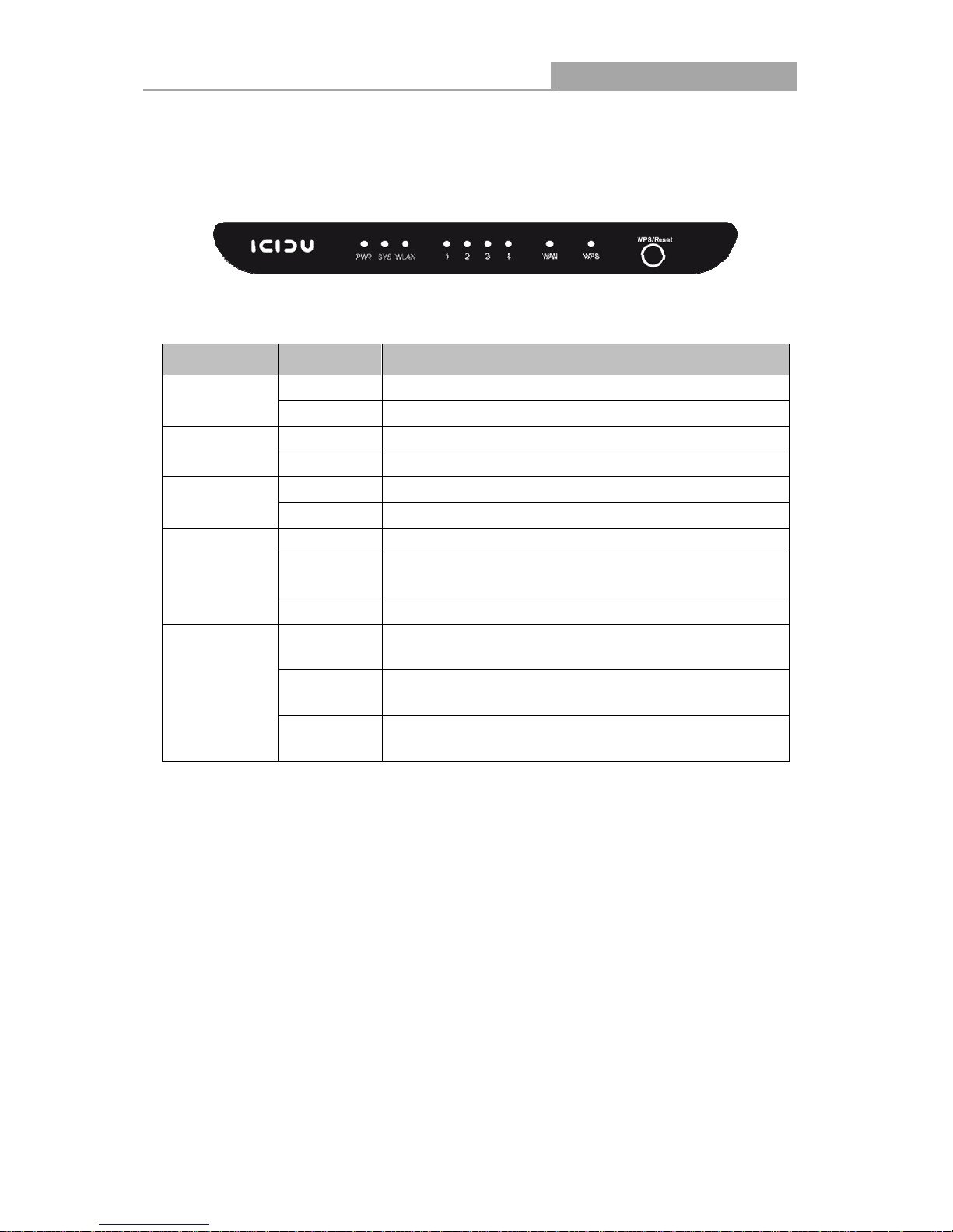
1.4.1 The Front Panel
Figure 1-1 Front Panel sketch
The Router’s LEDs are located on the front panel (View from left to right).
Name Status Indication
PWR
SYS
WLAN
WAN,
LAN 1-4
WPS
Note:
1. After a device is successfully added to the network by WPS function, the WPS LED will keep
on for about 5 minutes and then turn off.
Off Power is off.
On Power is on.
Flashing The Router is working properly.
On /Off The Router has a system error.
Off The Wireless function is disabled.
Flashing The Wireless function is enabled.
Off There is no device linked to the corresponding port.
On
Flashing There is an active device linked to the corresponding port.
Slow Flash
On
Quick Flash
There is a device linked to the corresponding port but
there is no activity.
A wireless device is connecting to the network by WPS
function. This process will last in the first 2 minutes.
A wireless device has been successfully added to the
network by WPS function.
A wireless device failed to be added to the network by
WPS function.
Table 1-1 The LEDs Description
2. When press and hold the WPS/Reset button for more than 5 seconds, you will reset the
router.
- 4 -
NI-7075349
Wireless Router 300N
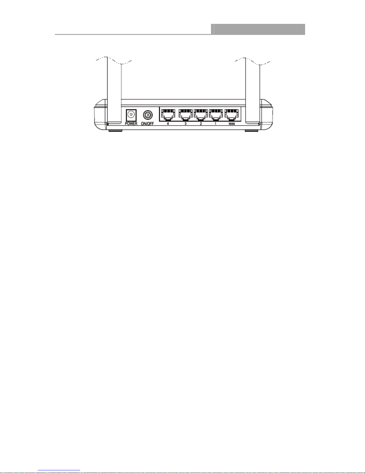
1.4.2 The Rear Panel
Figure 1-2 Rear Panel sketch
The following parts are located on the rear panel (View from left to right).
POWER: The Power socket is where you will connect the power adapter. Please use the
power adapter provided with this NI-707549 Wireless Router 300N.
ON/OFF: The switch for the power.
4,3,2,1 (LAN): These ports (4,3,2,1) connect the Router to the local PC(s).
WAN: This WAN port is where you will connect the DSL/cable Modem, or Ethernet.
Wireless antenna: To receive and transmit the wireless data.
- 5 -

NI-7075349
Wireless Router 300N
Chapter 2. Connecting the Router
2.1 System Requirements
Broadband Internet Access Service (DSL/Cable/Ethernet)
One DSL/Cable Modem that has an RJ45 connector (which is not necessary if the Router is
connected directly to the Ethernet.)
PCs with a working Ethernet Adapter and an Ethernet cable with RJ45 connectors
TCP/IP protocol on each PC
Web browser, such as Microsoft Internet Explorer, Mozilla Firefox or Apple Safari
2.2 Installation Environment Requirements
Place the Router in a well ventilated place far from any heater or heating vent
Avoid direct irradiation of any strong light (such as sunlight)
Keep at least 2 inches (5 cm) of clear space around the Router
Operating Temperature: 0~40 (32~104)
Operating Humidity: 10%~90%RH, Non-condensing
2.3 Connecting the Router
Before installing the Router, make sure your PC is connected to the Internet through the
broadband service successfully. If there is any problem, please contact your ISP. After that, please
install the Router according to the following steps. Don't forget to pull out the power plug and keep
your hands dry.
1. Power off your PC, Cable/DSL Modem, and the Router.
2. Locate an optimum location for the Router. The best place is usually at the center of your
wireless network.
3. Adjust the direction of the antenna. Normally, upright is a good direction.
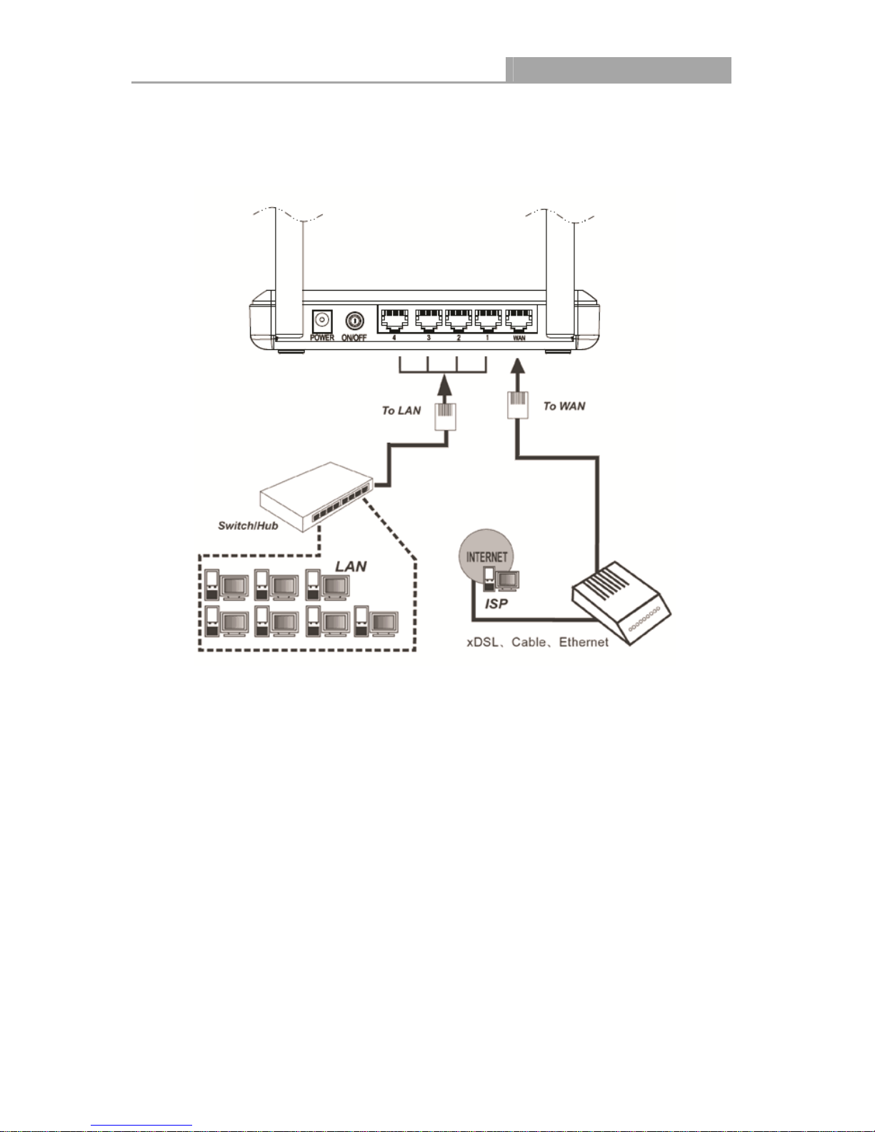
4. Connect the PC(s) and each Switch/Hub in your LAN to the LAN Ports on the Router, shown
in Figure 2-1. (If you have the wireless NIC and want to use the wireless function, you can
skip this step.)
5. Connect the DSL/Cable Modem to the WAN port on the Router, shown in Figure 2-1.
- 6 -
NI-7075349
Wireless Router 300N
6. Connect the power adapter to the power socket on the Router, and the other end into an
electrical outlet. The Router will start to work automatically.
7. Power on your PC and Cable/DSL Modem.
Figure 2-1 Hardware Installation of the PW-RN501D Wireless Router 300N
- 7 -

NI-7075349
Wireless Router 300N
Chapter 3. Quick Installation Guide
This chapter will show you how to configure the basic functions of your Wireless Router 300N
using Quick Setup Wizard within minutes.
3.1 TCP/IP Configuration
The default IP address is 192.168.1.1, and the default Subnet Mask is 255.255.255.0. These
values can be changed as you desire. In this guide, we use all the default values for description.
Connect the local PC to the LAN ports of the Router. And then you can configure the IP address
for your PC in the following two ways.
Configure the IP address manually
1) Set up the TCP/IP Protocol for your PC. If you need instructions as to how to do this,
please refer to Appendix B: "Configuring the PC".
2) Configure the network parameters. The IP address is 192.168.1.xxx ("xxx" is any number
from 2 to 254), Subnet Mask is 255.255.255.0, and Gateway is 192.168.1.1 (The
Router's default IP address)
Obtain an IP address automatically
1) Set up the TCP/IP Protocol in "Obtain an IP address automatically" mode on your PC.
If you need instructions as to how to do this, please refer to Appendix B: "Configuring the
PC”.
2) Then the built-in DHCP server will assign IP address for the PC.
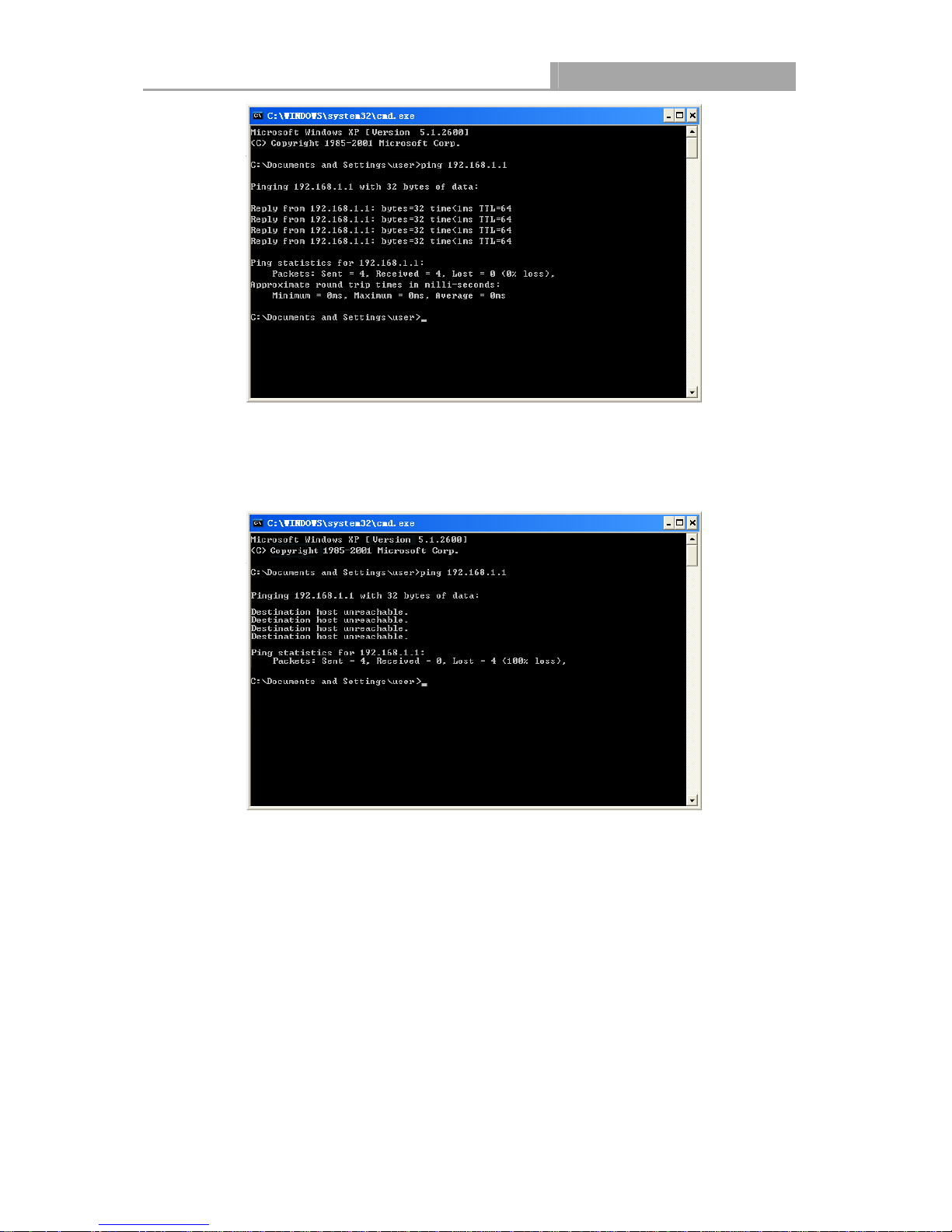
Now, you can run the Ping command in the command prompt to verify the network connection
between your PC and the Router. The following example is in Windows 2000 OS.
Open a command prompt, and type ping 192.168.1.1, and then press Enter.
If the result displayed is similar to the Figure 3-1, it means the connection between your PC
and the Router has been established well.
- 8 -
NI-7075349
Figure 3-1 Success result of Ping command
If the result displayed is similar to the Figure 3-2, it means the connection between your PC
and the Router is failed.
Wireless Router 300N
Please check the connection following these steps:
1. Is the connection between your PC and the Router correct?
Note:
The 1/2/3/4 LEDs of LAN ports which you link to on the Router and LEDs on your PC's adapter
should be lit.
2. Is the TCP/IP configuration for your PC correct?
If the Router's IP address is 192.168.1.1, your PC's IP address must be within the range of
192.168.1.2 ~ 192.168.1.254.
Note:
Figure 3-2 Failure result of Ping command
- 9 -
NI-7075349
Wireless Router 300N
3. Is the default LAN IP of the Router correct?
Note:
If the LAN IP of the modem connected with your router is 192.168.0.x, the default LAN IP of the
Router will automatically switch from 192.168.0.1 to 192.168.1.1 to avoid IP conflict. Therefore, in
order to verify the network connection between your PC and the Router, you can open a
command prompt, and type ping 192.168.0.1, and then press Enter.
3.2 Quick Installation Guide
With a Web-based utility, it is easy to configure and manage the Wireless Router 300N. The
Web-based utility can be used on any Windows, Macintosh or UNIX OS with a Web browser, such
as Microsoft Internet Explorer, Mozilla Firefox or Apple Safari.
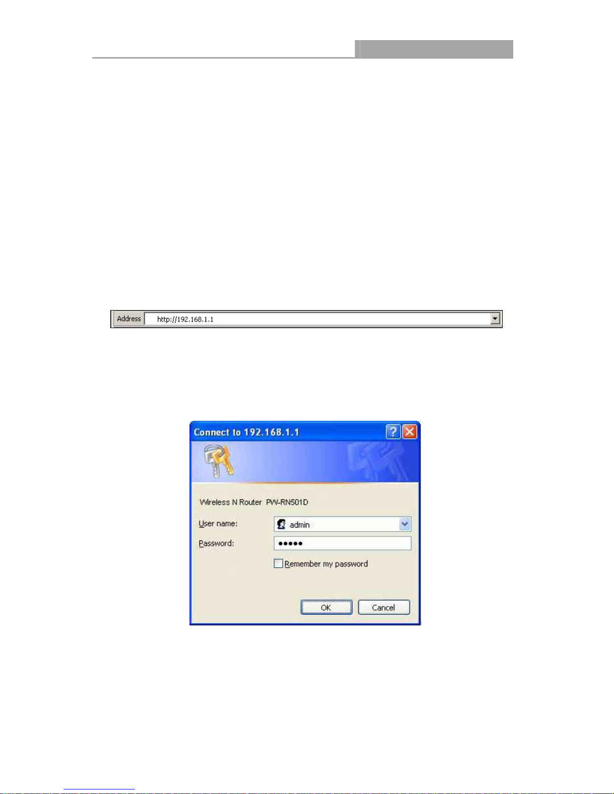
1. To access the configuration utility, open a web-browser and type in the default IP address
192.168.1.1 in the address field of the browser.
Figure 3-3
After a moment, a login window will appear, similar to the Figure 3-4. Enter admin for the
User Name and Password, both in lower case letters. Then click the OK button or press the
Enter key.
Figure 3-4 Login Windows
Log in the Router
Note:
If the above screen does not pop-up, it means that your Web-browser has been set to a proxy.
Go to Tools menu>Internet Options>Connections>LAN Settings, in the screen that appears,
cancel the Using Proxy checkbox, and click OK to finish it.
- 10 -
NI-7075349
Wireless Router 300N
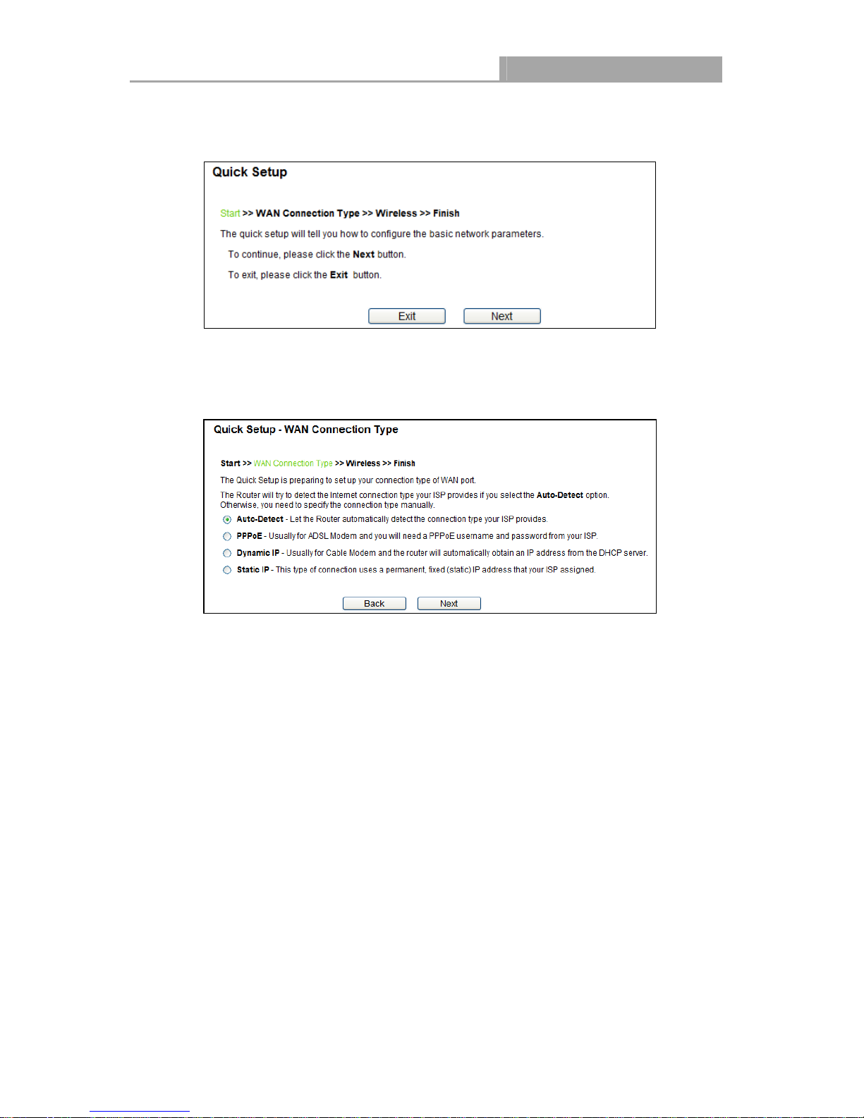
1. After successfully log in, you can click the Quick Setup menu to quickly configure your
Router.
Figure 3-5 Quick Setup
2. Click Next, and then WAN Connection Type page will appear, shown in Figure 3-6.
Figure 3-6 WAN Connection Type
The Router provides Auto-Detect function and supports three popular ways PPPoE,
Dynamic IP and Static IP to connect to the Internet. It’s recommended that you make use of
the Auto-Detect function. If you are sure of what kind of connection type your ISP provides,
you can select the very type and click Next to go on configuring.
3. If you select Auto-Detect, the Router will automatically detect the connection type your ISP
provides. Make sure the cable is securely plugged into the WAN port before detection. The
appropriate configuration page will be displayed when an active Internet service is
successfully detected by the Router.
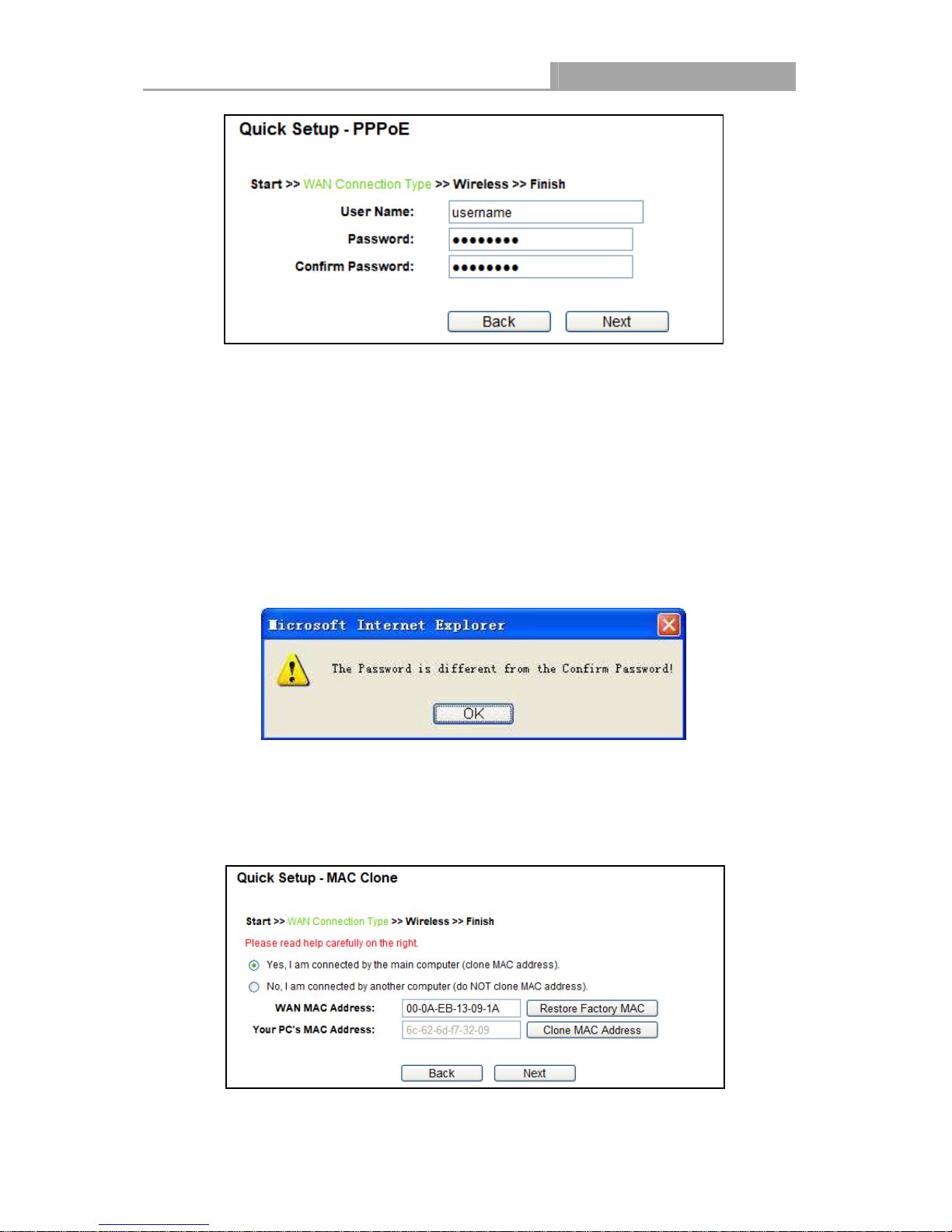
1) If the connection type detected is PPPoE, the next screen will appear as shown in Figure
3-7.
- 11 -
NI-7075349
Wireless Router 300N
Figure 3-7 Quick Setup - PPPoE
User Name/Password - Enter the User Name and Password provided by your ISP.
These fields are case sensitive. If you have difficulty with this process, please contact your
ISP.
Confirm Password - Re-enter the password provided by your ISP to ensure the
Password you entered is correct. If the Password is different from the Confirm Password,
the screen will appear as shown below. Click OK, and re-enter the Password and
Confirm Password.
2) If the connection type detected is Dynamic IP, the next screen will appear as shown in
Figure 3-8.
If you are visiting the Router from the main computer, please select Yes, and then
click Clone MAC Address.
Figure 3-8 Quick Setup – MAC Clone
- 12 -
NI-7075349
Wireless Router 300N
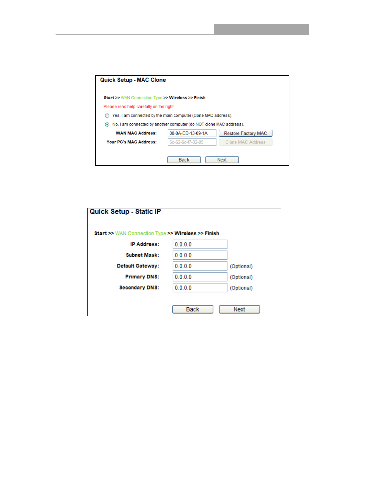
If you are visiting the Router from another computer, rather than the main computer,
please select No, and then enter the main computer’s MAC in the field WAN MAC
Address.
Figure 3-9 Quick Setup – MAC Clone
3) If the connection type detected is Static IP, the next screen will appear as shown in Figure
3-10.
IP Address - This is the WAN IP address as seen by external users on the Internet
(including your ISP). Enter the IP address into the field.
Subnet Mask - The Subnet Mask is used for the WAN IP address, it is usually
255.255.255.0.
Default Gateway - Enter the gateway IP address into the box if required.
Primary DNS - Enter the DNS Server IP address into the box if required.
Secondary DNS - If your ISP provides another DNS server, enter it into this field.
Figure 3-10 Quick Setup - Static IP
- 13 -
NI-7075349
Wireless Router 300N
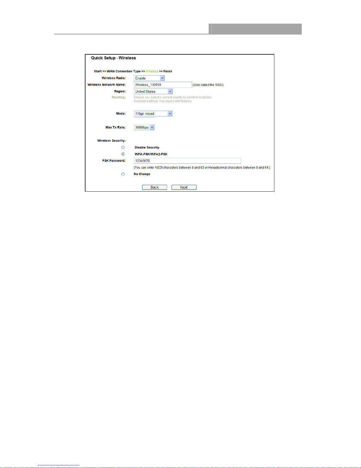
4. Click Next to continue, the Wireless settings page will appear as shown in Figure 3-11.
Figure 3-11 Quick Setup – Wireless
Wireless Radio - The wireless radio can only be enabled/disabled by using the WIFI
ON/OFF switch on the device.
Wireless Network Name - Enter a value of up to 32 characters. The same name of
SSID (Service Set Identification) must be assigned to all wireless devices in your
network. Considering your wireless network security, the default SSID is set to be
_XXXXXX (XXXXXX indicates the last unique six numbers of each Router’s MAC
address). This value is case-sensitive. For example, TEST is NOT the same as test.
Region - Select your region from the drop-down list. This field specifies the region
where the wireless function of the Router can be used. It may be illegal to use the
wireless function of the Router in a region other than one of those specified in this field.
If your country or region is not listed, please contact your local government agency for
assistance.
Note:
Limited by local law regulations, version for North America does not have region
selection option.
Mode - This field determines the wireless mode which the Router works on.
Channel Width - Select any channel width from the drop-down list. The default setting
is automatic, which can adjust the channel width for your clients automatically.
Channel - This field determines which operating frequency will be used. The default
channel is set to Auto, so the AP will choose the best channel automatically. It is not
- 14 -
NI-7075349
Wireless Router 300N
necessary to change the wireless channel unless you notice interference problems with
another nearby access point.
Max Tx Rate - You can limit the maximum transmission rate of the Router through this
field.
Disable Security - The wireless security function can be enabled or disabled. If
disabled, the wireless stations will be able to connect the Router without encryption. It is
recommended strongly that you choose one of following options to enable security.
WPA-PSK/WPA2-PSK - Select WPA based on pre-shared passphrase.
PSK Password - You can enter ASCII or Hexadecimal characters.
For ASCII, the key can be made up of any numbers 0 to 9 and any letters A to Z, the
length should be between 8 and 63 characters.
For Hexadecimal, the key can be made up of any numbers 0 to 9 and letters A to F,
the length should be between 8 and 64 characters.
Please also note the key is case sensitive, this means that upper and lower case
keys will affect the outcome. It would also be a good idea to write down the key and
all related wireless security settings.
No Change - If you chose this option, wireless security configuration will not change!
These settings are only for basic wireless parameters. For advanced settings, please refer to
4.6 Wireless.
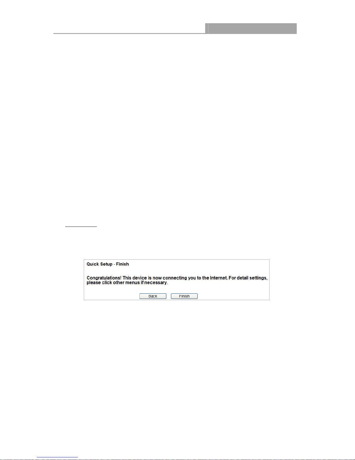
5. Click the Next button. You will then see the Finish page as shown in Figure 3-12.
Click the Finish button to finish the Quick Setup.
Figure 3-12 Quick Setup - Finish
- 15 -
NI-7075349
Wireless Router 300N
Chapter 4. Configuring the Router
This chapter will show each Web page's key functions and the configuration way.
4.1 Login
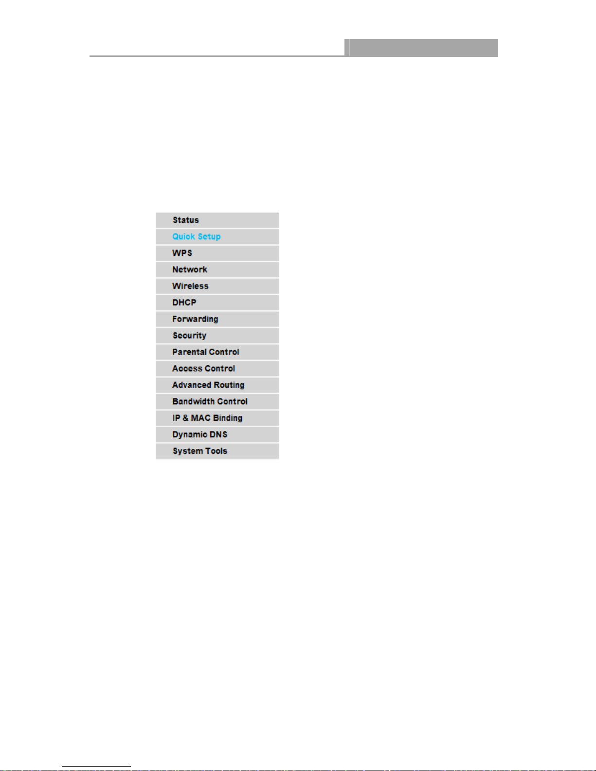
After your successful login, you will see the fifteen main menus on the left of the Web-based utility.
On the right, there are the corresponding explanations and instructions.
The detailed explanations for each Web page’s key function are listed below.
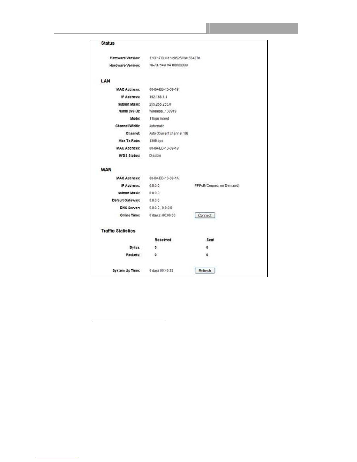
4.2 Status
The Status page provides the current status information about the Router. All information is
read-only.
- 16 -
NI-7075349
Wireless Router 300N
Figure 4-1 Router Status
4.3 Quick Setup
Please refer to 3.2 Quick Installation Guide.
4.4 WPS
This section will guide you to add a new wireless device to an existing network quickly by WPS
(Wi-Fi Protected Setup) function.
a). Choose menu “WPS”, and you will see the next screen (shown in Figure 4-2 ).
- 17 -
NI-7075349
Wireless Router 300N
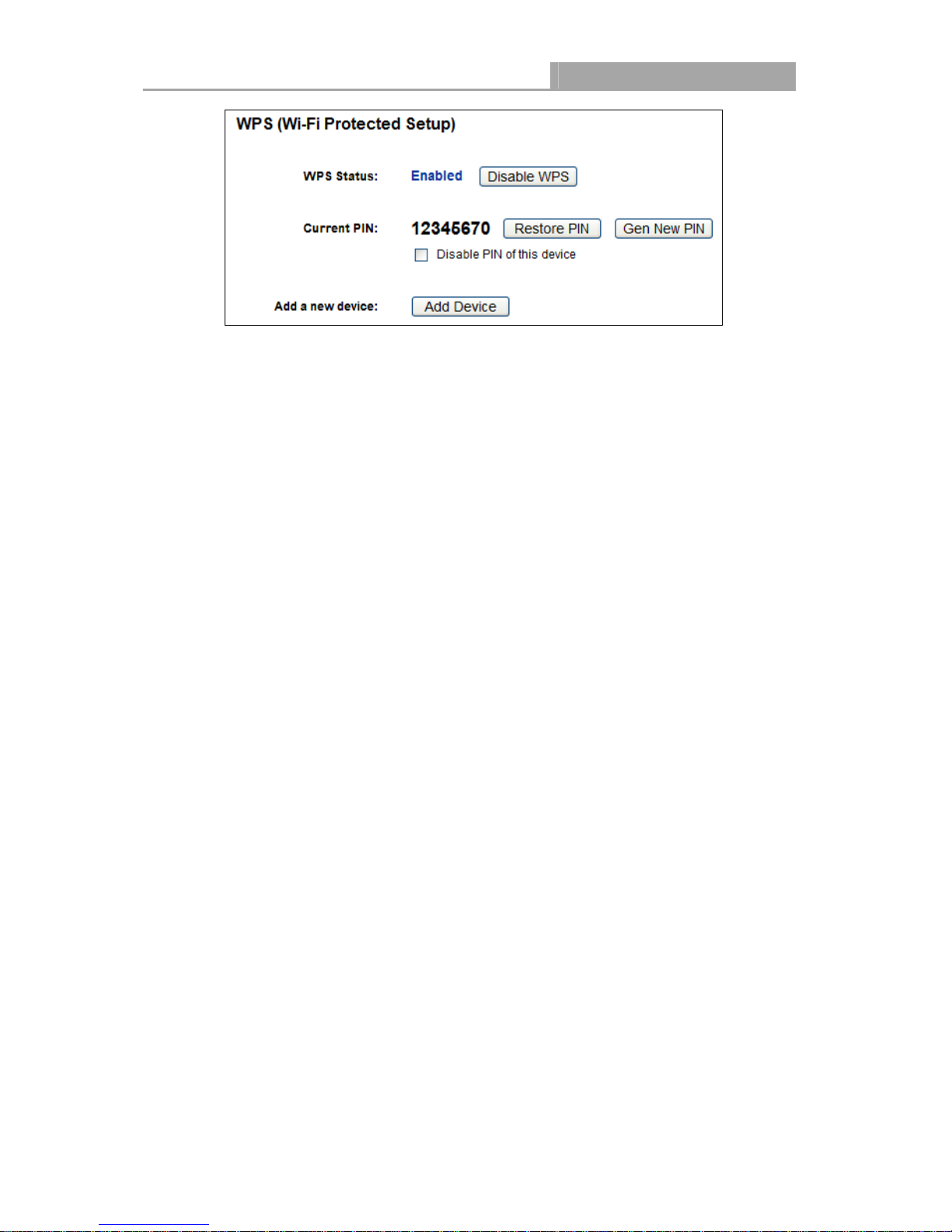
Figure 4-2 WPS
WPS Status - Enable or disable the WPS function here.
Current PIN - The current value of the Router's PIN is displayed here. The default PIN of the
Router can be found in the label attached on the router.
Restore PIN - Restore the PIN of the Router to its default.
Gen New PIN - Click this button, and then you can get a new random value for the Router's
PIN. You can ensure the network security by generating a new PIN.
Disable Device’s PIN - You can disable the Router’s PIN manually here. If the router
receives multiple failed attempts to authenticate an external registrar, this function will be
disabled automatically.
Add Device - You can add a new device to the existing network manually by clicking this
button.
b). To add a new device:
If the wireless adapter supports Wi-Fi Protected Setup (WPS), you can establish a wireless
connection between wireless adapter and Router using either Push Button Configuration (PBC)
method or PIN method.
Note:
To build a successful connection by WPS, you should also do the corresponding configuration of
the new device for WPS function meanwhile.
I. Use the Wi-Fi Protected Setup Button
Use this method if your client device has a Wi-Fi Protected Setup button.
Step 1: Press the WPS/RESET button on the back panel of the Router for one second.
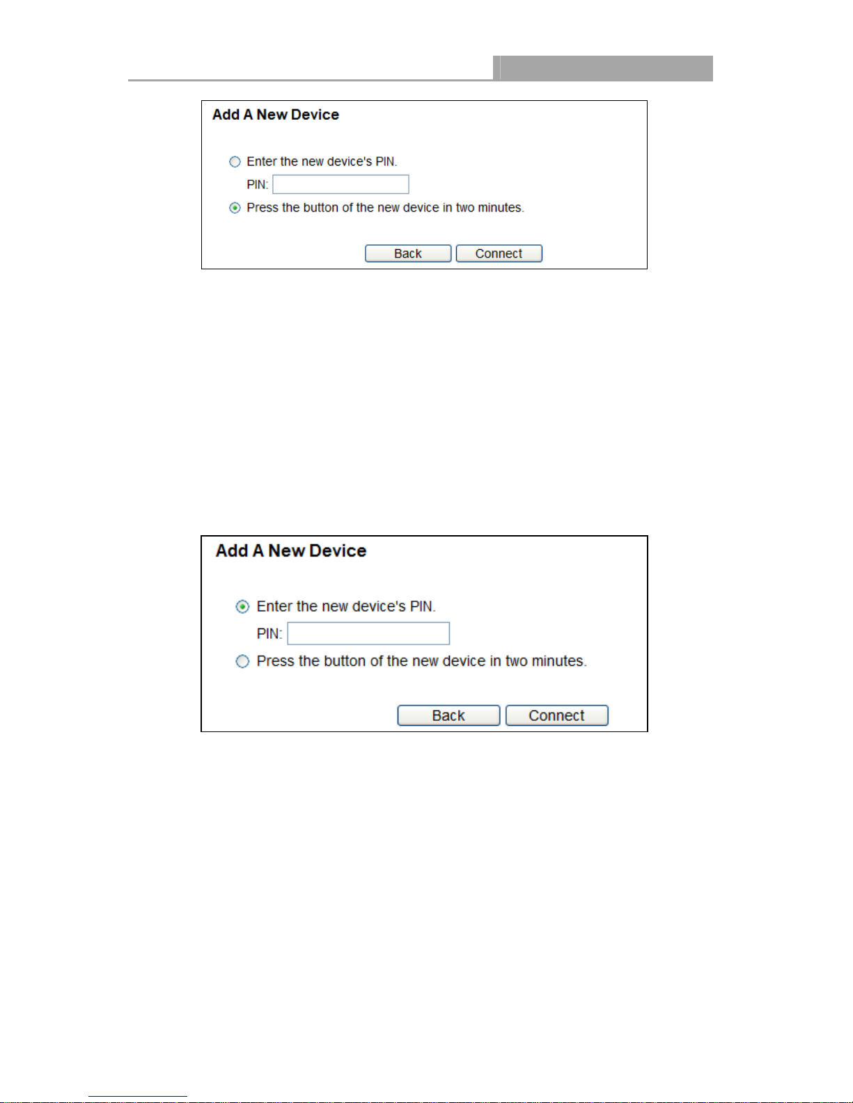
You can also keep the default WPS Status as Enabled and click the Add Device button
in Figure 4-2, then Choose “Press the button of the new device in two minutes” and
click Connect. (Shown in the following figure)
- 18 -
NI-7075349
Wireless Router 300N
Figure 4-3 Add A New Device
Step 2: Press and hold the WPS button of the client device directly.
Step 3: The Wi-Fi Protected Setup LED flashes for two minutes during the Wi-Fi Protected Setup
process.
Step 4: When the WPS LED is on, the client device has successfully connected to the Router.
Step 5: Refer back to your client device or its documentation for further instructions.
II. Enter the client device’s PIN on the Router
Use this method if your client device has a Wi-Fi Protected Setup PIN number.
Step 1: Keep the default WPS Status as Enabled and click the Add Device button in Figure 4-2,
then the following screen will appear.
Figure 4-4 Add A New Device
Step 2: Enter the PIN number from the client device in the field on the above WPS screen. Then
click Connect button.
Step 3: “Connect successfully” will appear on the screen of Figure 4-4, which means the client
device has successfully connected to the Router.
III. Enter the Router’s PIN on your client device
Use this method if your client device asks for the Router’s PIN number.
Step 1: On the client device, enter the PIN number listed on the Router’s Wi-Fi Protected Setup
screen. (It is also labeled on the bottom of the Router.)
Step 2: The Wi-Fi Protected Setup LED flashes for two minutes during the Wi-Fi Protected
- 19 -
NI-7075349
Wireless Router 300N
Setup process.
Step 3: When the WPS LED is on, the client device has successfully connected to the Router.
Step 4: Refer back to your client device or its documentation for further instructions.
Note:
1) The WPS LED on the Router will light green for five minutes if the device has been
2) The WPS function cannot be configured if the Wireless Function of the Router is disabled.
successfully added to the network.
Please make sure the Wireless Function is enabled before configuring the WPS.
4.5 Network
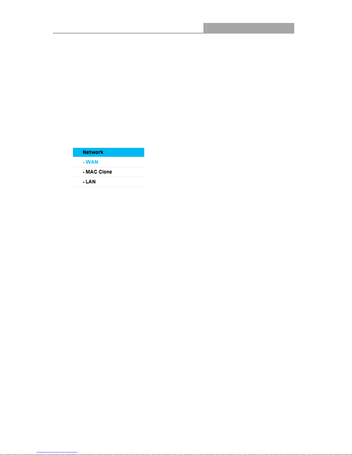
Figure 4-5 the Network menu
There are three submenus under the Network menu (shown in Figure 4-5): LAN, WAN and MAC
Clone. Click any of them, and you will be able to configure the corresponding function.
4.5.1 WAN
Choose menu “Network →→→→ WAN”, you can configure the IP parameters of the WAN on the
screen below.
1. If your ISP provides the DHCP service, please choose Dynamic IP type, and the Router will
automatically get IP parameters from your ISP. You can see the page as follows (Figure
4-6):
- 20 -
NI-7075349
Wireless Router 300N
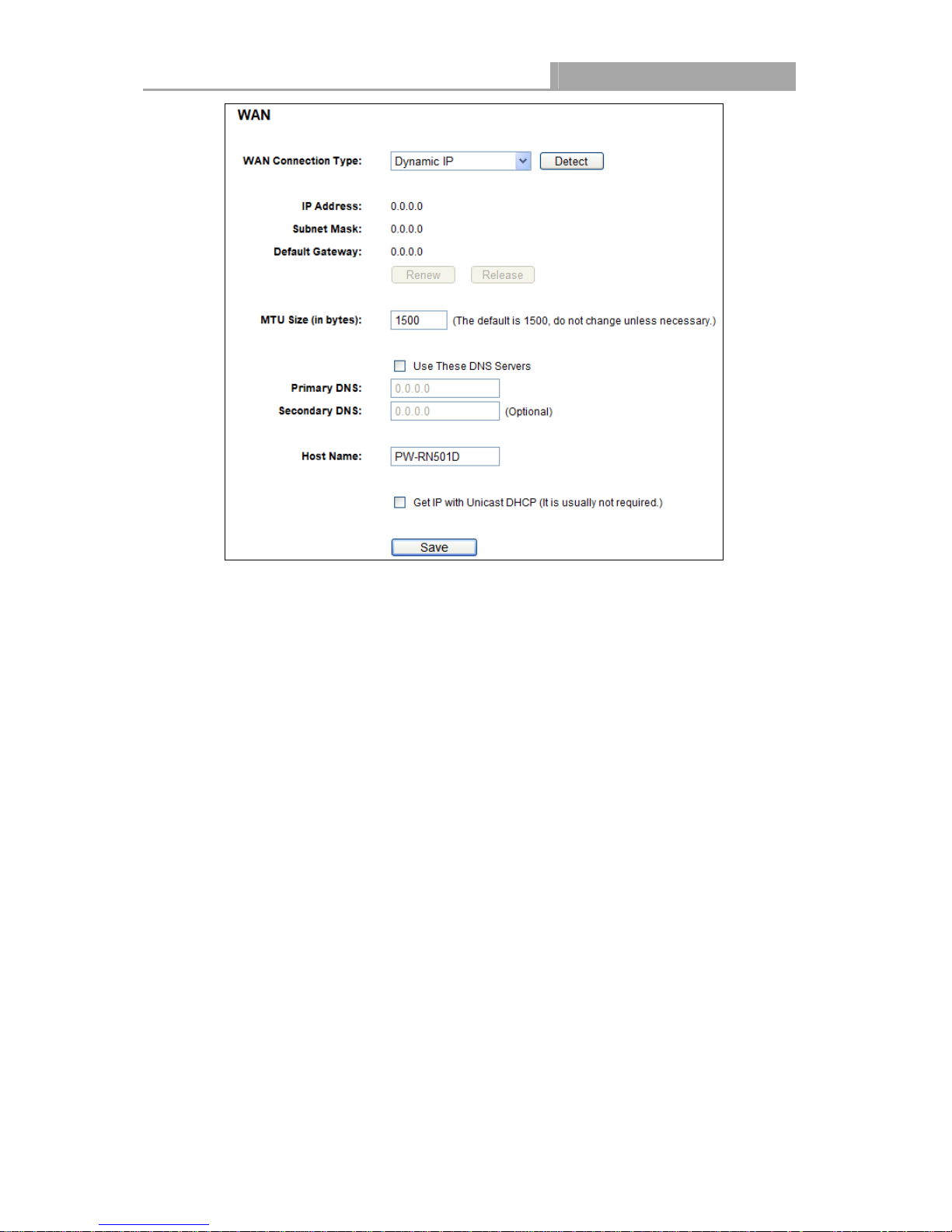
Figure 4-6
This page displays the WAN IP parameters assigned dynamically by your ISP, including IP
address, Subnet Mask, Default Gateway, etc. Click the Renew button to renew the IP
parameters from your ISP. Click the Release button to release the IP parameters.
MTU Size - The normal MTU (Maximum Transmission Unit) value for most Ethernet networks
is 1500 Bytes. It is not recommended that you change the default MTU Size unless required
by your ISP.
Use These DNS Servers - If your ISP gives you one or two DNS addresses, select Use
These DNS Servers and enter the primary and secondary addresses into the correct fields.
Otherwise, the DNS servers will be assigned dynamically from your ISP.
Note:
If you find error when you go to a website after entering the DNS addresses, it is likely that
your DNS servers are set up improperly. You should contact your ISP to get DNS server
addresses.
WAN – Dynamic IP
Host Name - This option specifies the Host Name of the Router.
Get IP with Unicast DHCP - A few ISPs' DHCP servers do not support the broadcast
applications. If you cannot get the IP Address normally, you can choose this option. (It is
rarely required.)
- 21 -

NI-7075349
Wireless Router 300N
Click the Save button to save your settings.
2. If your ISP provides a static or fixed IP Address, Subnet Mask, Gateway and DNS setting,
select Static IP. The Static IP settings page will appear, shown in Figure 4-7.
Figure 4-7
WAN - Static IP
IP Address - Enter the IP address in dotted-decimal notation provided by your ISP.
Subnet Mask - Enter the subnet Mask in dotted-decimal notation provided by your ISP,
usually is 255.255.255.0.
Default Gateway - (Optional) Enter the gateway IP address in dotted-decimal notation
provided by your ISP.
MTU Size - The normal MTU (Maximum Transmission Unit) value for most Ethernet networks
is 1500 Bytes. It is not recommended that you change the default MTU Size unless required
by your ISP.
Primary/Secondary DNS - (Optional) Enter one or two DNS addresses in dotted-decimal
notation provided by your ISP.
Click the Save button to save your settings.
- 22 -
NI-7075349
Wireless Router 300N
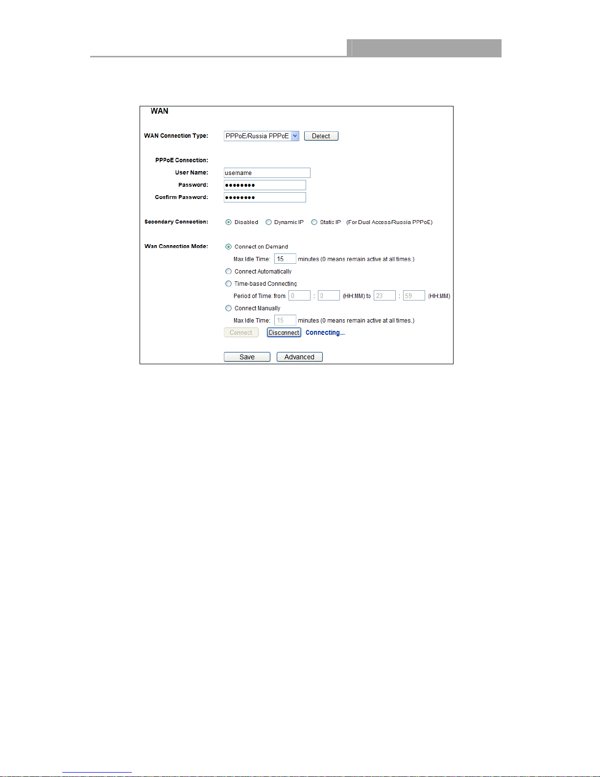
3. If your ISP provides a PPPoE connection, select PPPoE/Russia PPPoE option. Then
should enter the following parameters (Figure 4-8):
Figure 4-8
User Name/Password - Enter the User Name and Password provided by your ISP. These
WAN - PPPoE
fields are case-sensitive.
Secondary Connection - It’s available only for PPPoE Connection. If your ISP provides an
extra Connection type such as Dynamic/Static IP to connect to a local area network, then you
can check the radio button of Dynamic/Static IP to activate this secondary connection.
Disabled - The Secondary Connection is disabled by default, so there is PPPoE
connection only. This is recommended.
Dynamic IP - You can check this radio button to use Dynamic IP as the secondary
connection to connect to the local area network provided by ISP.
Static IP - You can check this radio button to use Static IP as the secondary connection
to connect to the local area network provided by ISP.
Connect on Demand - In this mode, the Internet connection can be terminated automatically
after a specified inactivity period (Max Idle Time) and be re-established when you attempt to
access the Internet again. If you want your Internet connection keeps active all the time,
please enter “0” in the Max Idle Time field. Otherwise, enter the number of minutes you want
to have elapsed before your Internet access disconnects.
Connect Automatically - The connection can be re-established automatically when it was
down.
- 23 -
NI-7075349
Wireless Router 300N
Time-based Connecting - The connection will only be established in the period from the
start time to the end time (both are in HH:MM format).
Note:
Only when you have configured the system time on “System Tools Time” page, will the
Time-based Connecting function can take effect.
Connect Manually - You can click the Connect/Disconnect button to connect/disconnect
immediately. This mode also supports the Max Idle Time function as Connect on Demand
mode. The Internet connection can be disconnected automatically after a specified inactivity
period and re-established when you attempt to access the Internet again.
Click the Connect button to connect immediately. Click the Disconnect button to disconnect
immediately.
Caution: Sometimes the connection cannot be terminated although you specify a time to Max Idle
Time because some applications are visiting the Internet continually in the background.
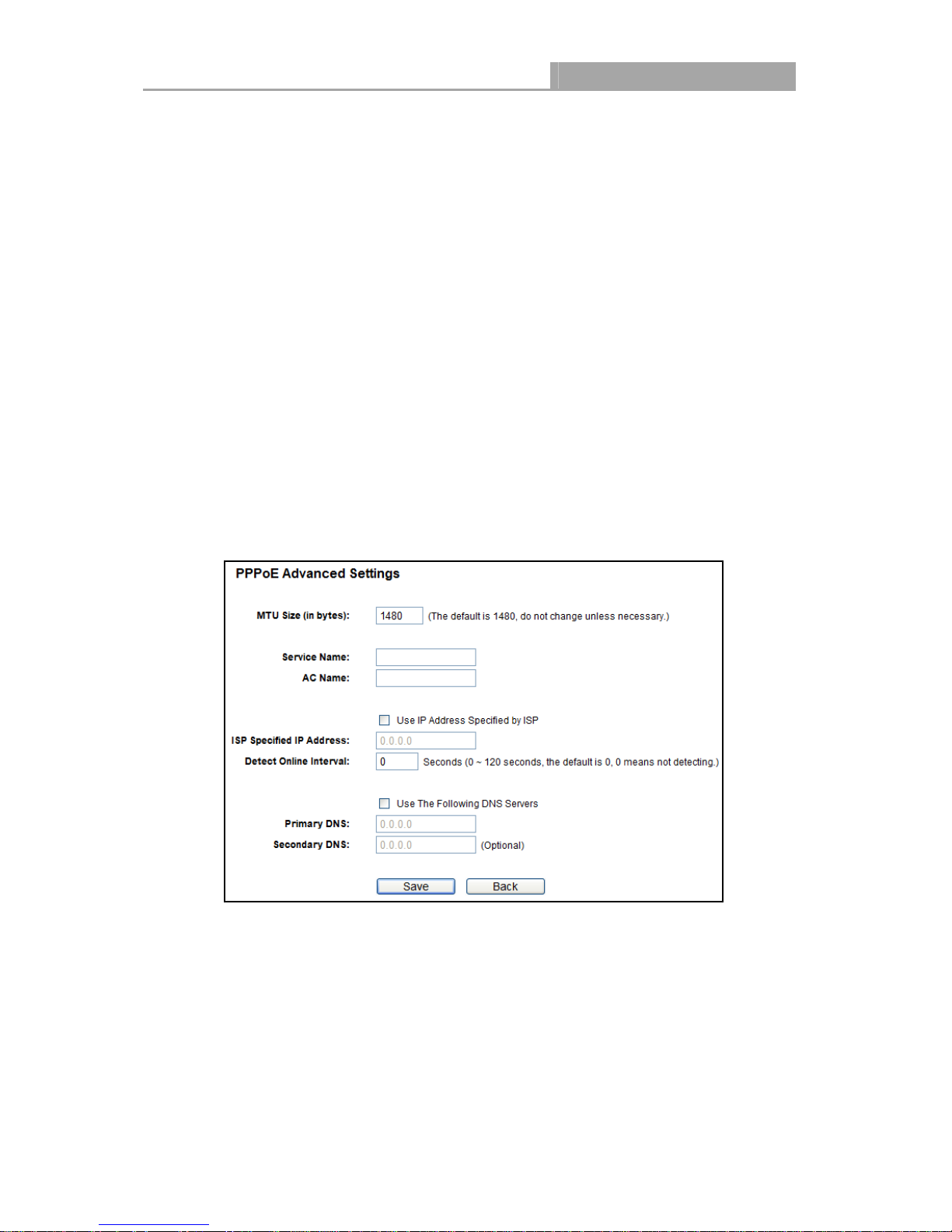
If you want to do some advanced configurations, please click the Advanced button, and the page
shown in Figure 4-9 will then appear:
MTU Size - The default MTU size is “1480” bytes, which is usually fine. It is not
recommended that you change the default MTU Size unless required by your ISP.
Service Name/AC Name - The service name and AC (Access Concentrator) name should
not be configured unless you are sure it is necessary for your ISP. In most cases, leaving
these fields blank will work.
ISP Specified IP Address - If your ISP does not automatically assign IP addresses to the
Figure 4-9 PPPoE Advanced Settings
- 24 -
 Loading...