

Page 1
ICE TECH SS / SP Technical Service
Manual
1
TECHNICAL SERVICE MANUAL
ICE CUBE MAKERS
MODELS:
ICETECH SS / SP 25
ICETECH SS / SP 35
ICETECH SS / SP 45
ICETECH SS / SP 60
ICETECH SS / SP 80
ICETECH SS / SP 135
CAREFULLY READ THE INSTRUCTIONS CONTAINED IN THIS MANUAL SINCE THEY PROVIDE IMPORTANT
INFORMATION RELATIVE TO SAFETY DURING INSTALLATION, USE AND MAINTENANCE.
Page 2

ICE TECH SS / SP Technical Service
Manual
2
TABLE OF CONTENTS
1. INTRODUCTION ............................................................................................................................................... 3
1.1. Warnings ..................................................................................................................................................... 3
1.2. Description .................................................................................................................................................. 4
1.3. Operating principle .................................................................................................................................... 4
1.4. Wiring diagram ........................................................................................................................................... 7
2. SPECIFICATIONS ............................................................................................................................................ 8
2.1. Installation diagrams for inlet/outlet tubes and dimensions ................................................................ 8
2.2. Consumption data, weights, crated dimensions and volumes ........................................................... 9
2.3. Production tables for Ice Flakers .......................................................................................................... 11
3. DELIVERY & UNPACKING ........................................................................................................................... 14
4. INSTALLATION ............................................................................................................................................... 16
4.1. Recommended placement of unit ......................................................................................................... 17
4.2. Water and Drainage ................................................................................................................................ 17
4.3. Connecting unit to water source (water-cooler units) ........................................................................ 18
4.4. Connecting unit to drain (water-cooled models) ................................................................................. 18
4.5. Electrical connection ............................................................................................................................... 18
5. OPERATION .................................................................................................................................................... 19
5.1. Preliminary check .................................................................................................................................... 19
5.2. Starting up ................................................................................................................................................ 19
6. ADJUSTMENTS .............................................................................................................................................. 20
7. MAINTENANCE AND CLEANING INSTRUCTIONS ................................................................................. 21
8. MAINTENANCE AND CLEANING PROCEDURES .................................................................................. 22
8.1. Special advise concerning R-404 Refrigerant .................................................................................... 25
9. TROUBLESHOOTING ................................................................................................................................... 26
Page 3

ICE TECH SS / SP Technical Service
Manual
3
1. INTRODUCTION
1.1. Warnings
This appliance should be installed by approved Technical Service Personnel.
This plug should be accessible at all times.
To reduce the risk of electrical shock, ALWAYS disconnect the machine BEFORE cleaning or
maintaining the equipment. Do not attempt to install, service, or modify this machine. Improper
use by other than specially trained technicians is extremely dangerous and may result in a fire or
electric shock.
This machine should not be placed outdoors or exposed to rain.
Connect to drinking water mains.
This appliance is not intended for use by young children or infirm persons without supervision.
Young children should be supervised to ensure that they do not play with the appliance.
IMPORTANT!
• DO NOT ATTEMPT TO SERVICE THIS MACHINE AS IT IS DANGEROUS AND COULD
CAUSE SEVERE DAMAGE TO THE UNIT.
•SERVICE SHOULD ONLY BE CARRIED OUT BY TRAINED, QUALIFIED PERSONNEL.
•WE STRONGLY RECOMMEND USING ONLY ORIGINAL REPLACEMENT PARTS
AVAILABLE FROM AN AUTHORIZED DISTRIBUTOR.
•WASTE AND OTHER MATERIAL SHOULD BE DISPOSED OF ACCORDING TO LOCAL
REGULATIONS AND PROCEDURES FOR WASTE DISPOSAL.
•CLEANING AND MAINTENANCE ARE NOT COVERED BY THE WARRANTY.
Page 4

ICE TECH SS / SP Technical Service
Manual
4
1.2. Description
Main Features of the Machine
Anti-blocking spray nozzles.
Pump without seals.
High pressure safety pressostats even in air-cooled machine.
Large condensers (work well at high ambient temperatures; and reduce cooling water
consumption in water-cooled machines).
Transparents cubes.
1.3. Operating principle
WHEN SWITCHING ON THE MACHINE FOR THE FIRST TIME, THE MACHINE SHOULD BE
PLACED ON THE DEFROSTING STAGE. To do so, turn the wheels on the timer until the
microswitches are depressed. At this moment, the compressor is working; the water inlet valve
and hot gas inlet valve are both open. The water bin fills with water, any excess is lost via the
maximum level overflow. After a period of time controlled by the timer (3-4 minutes usually), the
hot gas valve and water inlet valve are closed. The pump then sends water to the evaporator
where the ices cubes are gradually formed.
The evaporation temperature SPowly descends until it reaches the thermostat set point, which
sets off the timer at this temperature for about 16 minutes. Once this time has elapsed, the
defrosting stage (3-4 minutes) begins. The pump is off and the hot gas and water valves are open.
Some water is sent to the top of the evaporator to help the cubes unstick.
Once the defrosting stage is over, the cycle begins again, and so it continues until the bin is full
of ice, and contact between the bin thermostat situated at the top of the bin and the ice will stop
the machine. The bin thermostat will never stop the machine in mid-cycle.
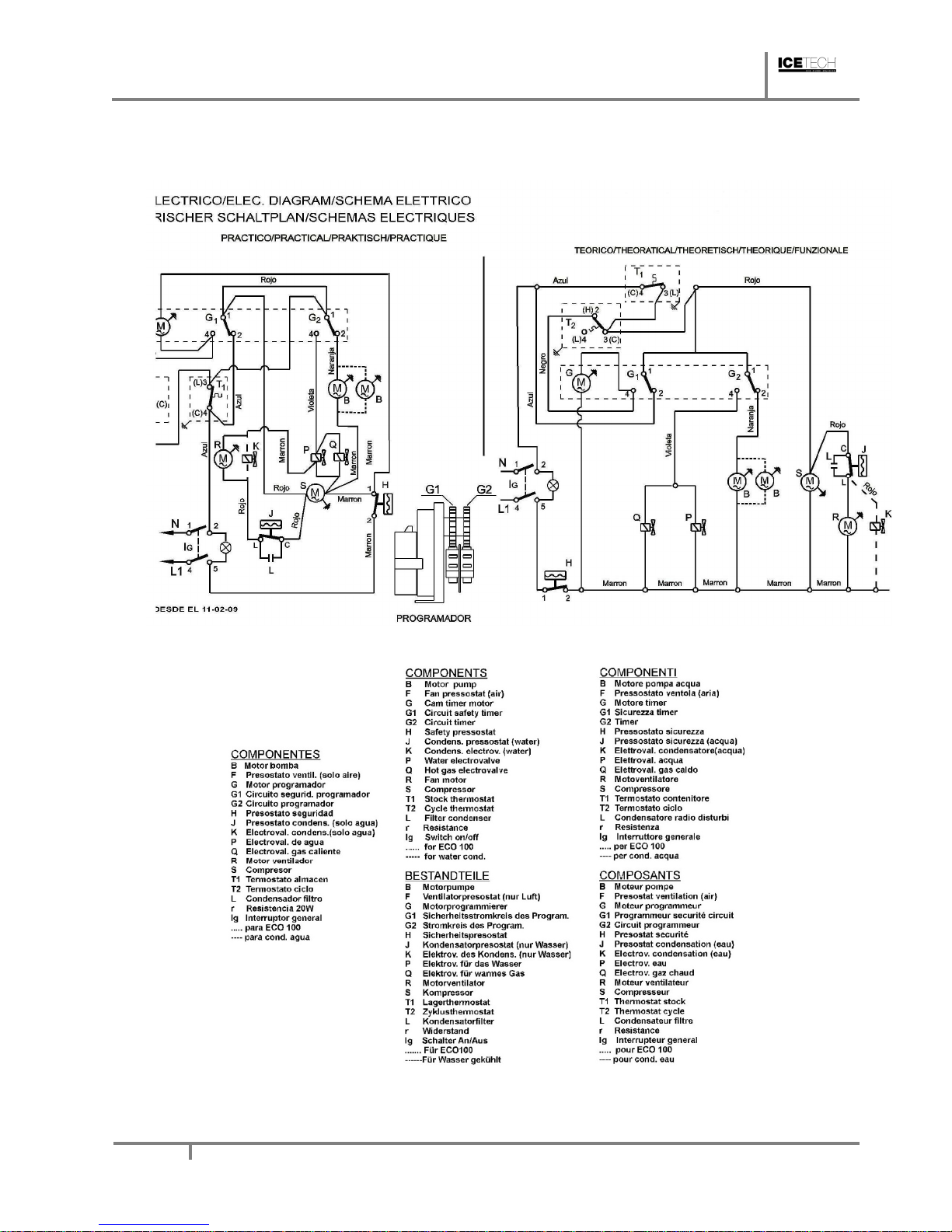
OPERATING PRINCIPLE FOLLOWING THE ELECTRIC DIAGRAM (TIMER ON DEFROST MICROSWITCHES DEPRESSED)
Current reaches the machine via the line connecting the blue (1) and brown (4) terminals. The
brown wire connects the compressor and timer motor. The blue wire connects bin thermostat T1
Page 5

ICE TECH SS / SP Technical Service
Manual
5
which closes the circuit with 3. A different blue wire goes to 2 on terminal G1 which at this moment
is connecting 1 and 4. A red wire connects bin thermostat T1 and micros G1 and G2 which close
the circuit with 4 and provide current via G1 to the timer G.
At this point the following are connected:
• COMPRESSOR (S)
• WATER INLET VALVE (P)
• HOT GAS VALVE (Q)
• TIMER MOTOR (G)
After 2 to 4 minutes micros G1 and G2 will open and close circuits 1-2. Via terminal 2 on micro
G2, current reaches the pump. Circuit 4 on micro G2 which provides current to the hot gas valve
(Q) and water inlet valve (P) will be interrupted. Since the thermostat is between 1 and 3 the timer
will receive no current. The compressor continues switched on.
Air-cooled machines have a fan (R) which is controlled by the pressostat (F). In water-cooled
models without pressostatic valve, pressostat (J) opens and closes the condenser electrovalve
(K).
Evaporator temperature decreases until the cycle thermostat (T2) set point is reached, at this
temperature circuit 1-2 will be closed and timer motor (G) will switch on.
Once the cycle is over, the pins on the timer wheels will force the micros to change circuits,
stopping the pump and opening the hot gas valve and water valve. The combined effect of hot
gas and water sprayed on the top of the evaporator will release the ice cubes and change the
position of the cycle thermostat (T2).
The ice production and defrosting cycle will continue until the ice storage bin is full, at which point
cycle thermostat (T1) will disconnect the machine, but never during a cycle, but at the beginning
of the defrosting stage, since during the production cycle, current will reach the pump via terminals
1-2 of micro G1.
The machine will remain disconnected until the level of ice in the bin drops below the thermostat
because of ice consumption. At this point the machine will connect automatically.
Page 6

ICE TECH SS / SP Technical Service
Manual
6
Page 7
ICE TECH SS / SP Technical Service
Manual
7
1.4. Wiring diagram
Page 8
ICE TECH SS / SP Technical Service
Manual
8
2. SPECIFICATIONS
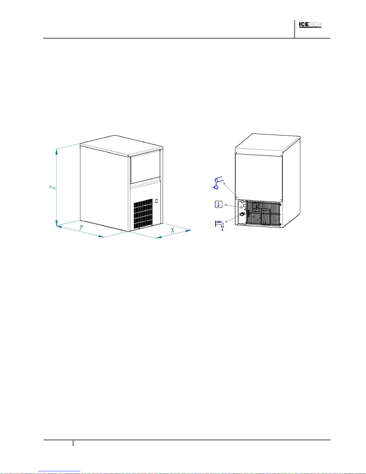
2.1. Installation diagrams for inlet/outlet tubes and dimensions
Page 9
ICE TECH SS / SP Technical Service
Manual
9
2.2. Consumption data, weights, crated dimensions and volumes
MODEL
WEIGHT
DIMENSIONS
WEIGHT
DIMENSION
WATER
COND.
WATER
TOTAL
NET
L/Hour
FABR.
L/Hour
L/Hour
(KG)
X*Y*Z
(KG)
(M3)
ICE TECH
25A
5.1 5.1 34 350x470x590 40 0.20
ICE TECH
25W
18 5.1 23.1 34 350x470x590 40 0.20
ICE TECH
35A
14 14 42 435x605x695 50 0.26
ICE TECH
35W
20 14 34 42 435x605x695 50 0.26
ICE TECH
45A
18.2 18.2 44 435x605x695 52 0.35
ICE TECH
45W
24 18.2 42.2 44 435x605x695 52 0.35
ICE TECH
60A
28.8 22.6 54 515x640x830 65 0.40
ICE TECH
60W
30 28.8 58.8 54 515x640x830 65 0.40
ICE TECH
80A
14.6 14.6 64 645x640x860 75 0.48
ICE TECH
80W
54 14.6 68.6 64 645x640x860 75 0.48
ICE TECH
135A
17.2 17.2 134 930x565x1050
145 0.63
ICE TECH
135W
59 17.2 76.2 134 930x565x1050
145 0.63
Page 10

ICE TECH SS / SP Technical Service
Manual
10
MODEL
HIGH PRESSURE
LOW
FUSE
REFRI.
PRESSURE
SAFETY
TOTAL
CONSUMPTION
MIN MAX
(GR)
Kg/cm
2
psi
Kg/cm2
psi
Kg/cm2
(A) (A) (W)
ICE TECH
25A
190 15 214 17 250 2.5 2 10 360
ICE TECH
25W
190 15 214 17 250 2.5 2 10 360
ICE TECH
35A
230 15 214 17 250 2.5 2.2 10 400
ICE TECH
35W
270 15 214 17 250 2.5 2.2 10 400
ICE TECH
45A
230 15 214 17 250 2.5 3.2 10 450
ICE TECH
45W
270 15 214 17 250 2.5 3.2 10 450
ICE TECH
60A
380 15 214 17 250 2.5 3.5 10 460
ICE TECH
60W
350 15 214 17 250 2.5 3.5 10 460
ICE TECH
80A
400 15 214 17 250 2.5 3 10 720
ICE TECH
80W
380 15 214 17 250 2.5 3 10 720
ICE TECH
135A
380 15 214 17 250 2.5 4.5 10 1150
ICE TECH
135W
390 15 214 17 250 2.5 4.5 10 1150
Page 11

ICE TECH SS / SP Technical Service
Manual
11
2.3. Production tables for Ice Flakers
ICE TECH 25
Tw/Ta 45
40 35 30 25 20 15 10
35
6 8 10 12 13 13 14 14
30
9 12 13 15 16 17 17 17
25
12 15 16 18 19 20 20 20
20
15 17 19 20 22 22 23 23
15
17 19 21 23 24 25 25 25
10
19 21 23 25 26 26 27 27
5
21 23 25 26 27 28 28 28
ICE TECH 35
Tw/Ta 45
40 35 30 25 20 15 10
35
9 12 14 16 18 19 19 19
30
9 13 16 19 21 23 24 24
25
18 21 23 25 27 28 20 20
20
21 24 27 29 30 31 32 32
15
24 27 30 32 34 35 35 35
10
27 30 33 35 36 37 38 38
5
29 32 35 37 39 40 40 40
Page 12

ICE TECH SS / SP Technical Service
Manual
12
ICE TECH 45
Tw/Ta 45
40 35 30 25 20 15 10
35
11 15 19 21 23 24 25 25
30
17 21 25 27 29 30 31 31
25
23 27 30 32 34 36 36 36
20
27 31 35 37 39 40 41 41
15
32 35 39 41 43 45 45 45
10
35 39 42 45 47 48 49 49
5
38 42 45 48 50 51 52 51
ICE TECH 60
Tw/Ta 45
40 35 30 25 20 15 10
35
14 19 23 26 28 30 31 31
30
21 26 30 33 36 37 38 38
25
28 33 37 40 42 44 44 44
20
34 38 42 46 48 50 50 50
15
39 43 47 51 53 55 55 55
Page 13

ICE TECH SS / SP Technical Service
Manual
13
10
43 48 52 55 57 59 60 60
5
46 51 55 58 61 62 63 63
ICE TECH 80
Tw/Ta 45
40 35 30 25 20 15 10
35
19 26 31 36 39 41 42 42
30
29 36 41 46 49 51 52 41
25
38 45 50 54 58 60 61 61
20
46 53 58 62 66 68 69 69
15
53 59 65 69 72 75 76 75
10
59 65 71 75 78 80 81 81
5
63 70 75 80 83 85 86 86
ICE TECH 135
Tw/Ta 45
40 35 30 25 20 15 10
35
30 40 48 55 60 63 65 64
30
45 55 63 70 75 78 80 80
25
59 69 77 84 89 92 94 93
20
71 81 89 69
101
104
106
105
15
81 91
100
106
111
115
116
116
Page 14

ICE TECH SS / SP Technical Service
Manual
14
3. DELIVERY & UNPACKING
Upon receipt, thoroughly inspect the packing container. If there appears to be damage to the
container contact the shipper immediately. Unpack unit in the presence of delivery personnel
noting any damage on the waybill.
ITV packing bears the “Green Point” on all models according to the European Directives on
management of Packaging and Waste Disposal.
Be sure to include model name and serial number on all claims. Serial number is located in the
following three places:
(1) Packing
There is a label stuck onto the cardboard packing bearing this serial number (1).
(2) Machine body
On the back of the machine (1).
(3) Rating plate and serial number
Located at the back of the machine.
Water cooled machines: check that the drainage hose at the back of the machine is in good condition.
Verify that the installation kit is inside the bin, and has the following pieces: scoop, 3/4’ water hose, two
small filters and user manual.
In all models there is a large particle filter (5 micres) with accessories, and an ice dispersion cone.
10
90
100
109
115
120,
123
125
125
5
98
108
116
123
128
131
132
132
Page 15

ICE TECH SS / SP Technical Service
Manual
15
Page 16

ICE TECH SS / SP Technical Service
Manual
16
WARNING: DO NOT LEAVE PACKING MATERIALS (PLASTIC BAGS, CARDBOARD
BOXES, ETC.) WITHIN REACH OF CHILDREN.
4. INSTALLATION
The ice cube maker is delivered on a small wooden pallet and is protected with a cardboard box and
packaging. Loosen the cardboard box by cutting the straps, then lift vertically.
After having removed the packaging, make sure the machine is complete. If in doubt do not use it
and go to the distributor who sold it to you.
This operation has to be performed with the wooden base structure firmly placed on the ground. All
packaging elements (plastic bags, cartons, etc.) must not be left at children's reach, since they are
a potential source of danger.
Place the machine where it is to be installed, and verify, using a level control, that the machine is in
a horizontal position.
IMPORTANT!
If the gap between the back of the machine and the wall of the room/bar is not sufficient, or if it is
going to receive hot air from another machine, we strongly advise you, in case of not being able to
change the location of the machine, to INSTALL A WATER-COOLED MACHINE.
Page 17

ICE TECH SS / SP Technical Service
Manual
17
Bear in mind the previous considerations if the premises where the machines is located are very
dusty, or smoky. If possible make arrangements so that the machine may be moved frontwise in
order to carry out maintenance.
4.1. Recommended placement of unit
IMPORTANT!
ICETECH machines are intended to operate at room temperature between 5°C and 43°C and
with water temperature ranging between 5°C and 35°C. You may encounter evaporator/gearbox
malfunctions should the machine run at temperatures below the recommended minimum. When
running above maximum recommended temperatures you can expect shorter compressor life and
decreased production.
Air-cooled units receive air input via front of machine and expel air through rear grille.
IMPORTANT!
If front and/or rear ventilation is inadequate, obstructed, or in close proximity to other heat
producing machinery, use of a water-cooled unit is strongly recommended.
The above mentioned also applies should unit be installed in an area where dust, smoke, or other
airborne pollutants may be present. Units—especially air-cooled ones—should not be installed in
kitchens. To facilitate access to condenser and/or water pressure valve, allow sufficient space at
front of the machine. Ensure that flooring is firm and even.
4.2. Water and Drainage
Water quality influences ice hardness, flavour, and quality as well as condenser life.
Keep in mind the following points:
a) WATER IMPURITIES: Major impurities are eliminated by filters provided. Filters should be
cleaned regularly depending on purity of water. For minor impurities we recommend
installing a 5-micron filter.
b) WATER WITH MORE THAN 500 PPM: Ice will be less hard and tend to adhere. Lime
deposits may impede proper functioning. In water cooled models, condenser obstruction
is likely. Installation of a high quality water softener is recommended.
Page 18

ICE TECH SS / SP Technical Service
Manual
18
c) CHLORINATED WATER: Chlorine taste can be avoided by installing a carbon filter
(NOTE: You may encounter water with all aforementioned properties.)
d) PURIFIED WATER: A 10% reduction in overall production may occur.
4.3. Connecting unit to water source (water-cooler units)
• Use 1.3 m. flexible tube (with the two filters attached) provided. NOTE: We advise using a
single faucet fixture.
• Water pressure should be between 0.7 and 6 Kgs/cm2. (10/85 Psi.)
• If water pressure exceeds these values, installation of appropriate corrective units will be
necessary.
• It is important that water tubing does not come close to or in contact with any heat sources
or heat generated by unit as this could decrease production.
4.4. Connecting unit to drain (water-cooled models)
• Drain must be located at least 150mm below machine level. Drain tube must have an inner
diameter of 30mm and a minimum gradient of 3 cm per metre.
4.5. Electrical connection
• Unit is provided with a 1.5 m cord and Schucko socket.
•It is recommended to install a switch and adequate fuses. Nominal voltage and intensity are
indicated on rating plate as well as on this manual's technical pages. Voltage fluctuations greater
than 10% can cause problems or prevent machine from starting.
•Line to base of plug must have a minimum section=2.5 mm2.
•Be sure voltage indicated on rating plate corresponds to that of mains supply.
IMPORTANT!
Supply socket must be properly earthed. Be sure to check standard for country where appliance
is going to be installed.
Page 19

ICE TECH SS / SP Technical Service
Manual
19
5. OPERATION
5.1. Preliminary check
a) Is machine levelled?
b) Are voltage and frequency of mains supply the same as indicated on rating plate?
c) Is drainage system working properly?
d) Is air circulation and room temperature adequate? (Air-cooled models)
AMBIENT TEMPERATURE WATER TEMPERATURE
MAXIMUM 40° C 35° C
MINIMUM 5° C 5° C
e) Is water pressure adequate?
MAXIMUM 0.7 Kg/cm2
MINIMUM 6 Kg/cm2
ATENTION: Check that voltage and mains frequency is the same as in the rating plate.
5.2. Starting up
Once preliminary check has been completed (ventilation, connections, temperature, etc.),
proceed as follows:
1) Open water faucet. Check for leaks.
2) Plug machine into electricity mains supply.
3)Push the (blue) switch found on the machina front side.
4) Ensure that there are no strange vibrations or scraping sounds
5) Check that the water curtain moves freely
6) Verify that spray nozzles are all working
7) After 10 minutes, check that the water bin has no leaks on the maximum level overflow.
Page 20

ICE TECH SS / SP Technical Service
Manual
20
8) At the cycle’s end, there should be frost formed on the compressor inlet tube except for the
last 50 mm.
IMPORTANT!
Advise the final user on maintenance procedures which are not included in warranty, as well as
those breakdowns caused by neglect of proper maintenance procedures.
6. ADJUSTMENTS
Condenser water valve pressostat
This pressostat controls high pressure by opening and closing the condenser water valve.
Differential is a fixed 1 Kg/cm2 (14 psi.). The valve closes at 16 Bar (228 psi.) which is
equivalent to a water exit temperature of 38ºC. Below this pressure it will be difficult to unstick
the cubes in the defrosting stage. Above this pressure, compressor life and ice production are
both reduced. Pressure can be increased by turning the small screw on the pressostat
clockwise. A full turn is equivalent to about 1.5 Bar.
Pressure Control
Fan pressostat (air condensation)
Pressure Control operates on high pressure by starting and stopping fan. Differential is a fixed
(1Bar or 14 psi.) Cut-off pressure must be 16 Bar (228 psi.) Low pressure values may cause
Page 21

ICE TECH SS / SP Technical Service
Manual
21
gearbox malfunction. Pressure values higher than 16 Kg/cm2 may shorten compressor life and
diminish ice production.
Pressure can be regulated by rotating screw on Pressure Control Valve (clockwise to increase
pressure). One full turn is aquivalent to about 1.5 Bar.
Safety pressostat
This safety device trips when pressure is too high. Pressure might reach
the limit when:
a) Air circulation is not sufficient, room temperature is too high, condenser
is dirty or fan motor is broken. (air-cooled models)
b) Insufficient water in the cooling circuit, inlet water temperature is too high
or fan motor is broken (water -cooled models).
HIGH PRESSURE SET POINTS (non-adjustable):
27-21 Kg/cm2 (380-296 Psi.)
7. MAINTENANCE AND CLEANING INSTRUCTIONS
IMPORTANT!
**Maintenance and cleaning procedures as well as problems derived from failing to carry them
out are not covered by the warranty.
Proper maintenance is essential to obtain favourable ice quality and optimum functioning of unit.
Frequency depends on water quality and characteristics of room where unit is installed.
IMPORTANT:
** Maintenance/cleaning procedures should take place at least once every six months. If
concentration of air pollutants is high, complete procedures on a monthly basis.
Page 22

ICE TECH SS / SP Technical Service
Manual
22
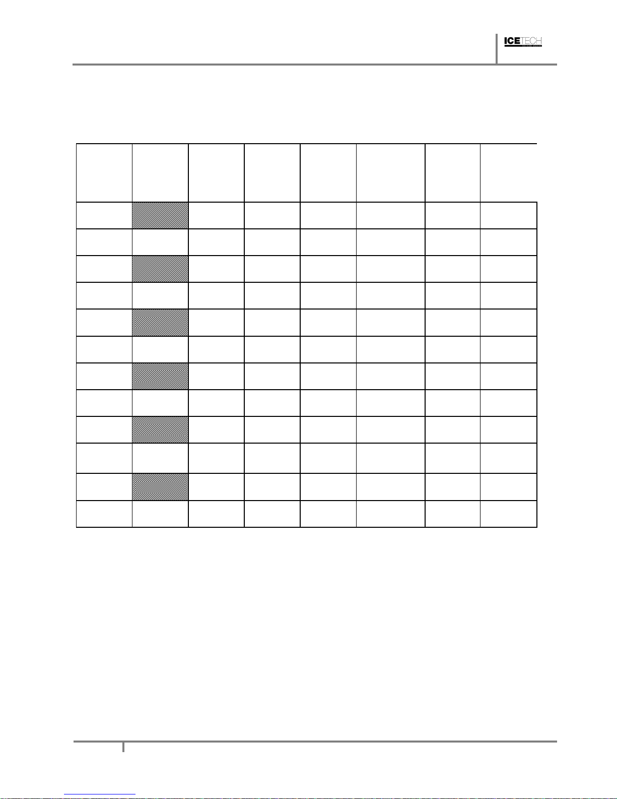
MAINTENANCE TABLE:
PROCEDURE
MONTHLY
QUARTERLY
HALF
YEARLY
YEARLY BIENNIAL DURATION
Air condenser
cleaning
30 minutes
Water condenser
cleaning
90 minutes
Inyectors cleaning
30 minutes
Fabrication head
filter cleaning
30 minutes
Water circuit
cleaning
45 minutes
Sanitary cleaning
30 minutes
Water filter
cleaning/replacement
30 minutes
Gearbox cleaning
--
General unit cleaning
--
Depending on room characteristics
Depending on water quality
Carried out by owner
Essential
Maintenance and cleaning procedures as well as problems derived from failing to carry them out
ARE NOT COVERED BY THE WARRANTY. Service personnel will invoice you for travel
expenses, time invested and materials required for maintenance and cleaning of unit.
8. MAINTENANCE AND CLEANING PROCEDURES
WARNING: Unit should always be disconnected during maintenance/cleaning procedures.
Water Condenser
1) Disconnect machine.
2) Close water faucet.
3) Disconnect water entry/exit from condenser.
Page 23

ICE TECH SS / SP Technical Service
Manual
23
4) Prepare a solution of 50% phosphoric acid in distilled water.
5) Distribute solution through condenser. (Solution is more effective at 35°-40°C).
WARNING!
DO NOT USE HYDROCHLORIC ACID
Air Condenser
1) Disconnect machine.
2) Close water faucet.
3) Clean condenser using a vacuum cleaner, soft brush and/or low-pressure air.
Evaporator/Water Trough
1) Disconnect machine.
2) Remove drain plug situated in lower bearing.
3) Use a container to collect water.Allow water to flow for 2 to 3 minutes.
4) Close water entrance and replace plug.Prepare a solution of 50% phosphoric acid in distilled
water.
Do not use hydrochloric acid.
5) SPowly pour solution into water deposit. (Solution is more effective at 35°-40°C).
6) Let solution stand for 20 minutes.
7) Remove lower plug and empty deposit.
8) Replace plug.
9) Fill container with solution to maximum capacity.
10) Connect machine and wait for unit to automatically shut off when remaining liquid drains.
WARNING:** Discard ice produced during cleaning procedure.
11) Disconnect machine.
12) Remove plug.
13) Open faucet and let water run for 2 to 3 minutes.
14) Close faucet, place plug, open faucet and connect the machine.
**At this point sanitary cleaning starts
15) SPowly add bleach to water deposit for at least 5 minutes.
Page 24

ICE TECH SS / SP Technical Service
Manual
24
16) Allow machine to make ice for at least 15 minutes.
WARNING:** Discard ice produced during cleaning procedure.
17) Disconnect unit, place cover and check for water leaks.
18) Change joint in water plug if necessary.
19) Replace filters if necessary. (Machines provided with 5mm filters).
20) Reconnect machine.
Cleaning the ice bin
1) Unplug the machine, turn off water supply, and empty storage bin of ice
2) Wipe with a kitchen cloth soaked in bleach and detergent
3) If white lime stains do not vanish, rub with some lemon or vinegar, wait for a few minutes and
wipe with the cloth again.
4) Rinse with plenty of water, dry, and run the machine
Cleaning the outside of the machine
Follow the same procedure as for the ice bin.
Spray nozzles and connecting pipes
1) Remove the curtain (it can be cleaned with vinegar or phosphoric acid, rinse, clean with bleach,
rinse)
2) Remove the metal grill and clean likewise
3) Pull the connecting pipe upwards with some force.
4) Remove the spray nozzles by pulling them out one by one from the square pipe, and remove
the pipe ends. Clean everything
5) Pull out the round wire mesh filter with some force.
6) Put everything back together again.
ATTENTION; IT IS ESSENTIAL THAT SPRAY NOZZLES ARE COMPLETELY
PERPENDICULAR, OTHERWISE SOME CUBES MAY NOT BE FORMED WELL.
7) Place the grill over the nozzles, with the back SPots secure.
8) Install the curtain, ensuring that all of the strips can move freely.
9) Run the machine but discard the first set of ice cubes.
Cleaning the water inlet filters
Page 25

ICE TECH SS / SP Technical Service
Manual
25
These round wire gasket filters placed on either end of the water hose to mains, often become
blocked in the first few days of use, especially when the plumbing installation is new. Clean them
under a jet of water.
Checking for water leaks
This must be done whenever maintenance is carried out on the machine: check all water
connexions, braces, tubes and hoses in order to eliminate leaks and prevent breakages and
flooding. Check that the valve closes tightly on models with an automatic cleaning system.
8.1. Special advise concerning R-404 Refrigerant
• R-404 is a mixture of 3 liquid-phase gases. On evaporating, the 3 component gases separate
• Always use the liquid phase valve (at the end of condenser or accumulator) for refills and
purges.
• When replacing a compressor, wash inside of circuit with a suitable solvent + pump, dry with
nitrogen gas, REPLACE THE DRIER WITH ONE SUITABLE FOR R-404, which must also
have ANTI-ACID properties.
• If you need to add oil, use one which is specific for R-404 (POE). If you are in doubt, contact
the machine manufacturer.
• If there is a leak anywhere in the circuit where R-404 in the GAS phase, and a refill of over
10% is required, then ALL THE GAS IN THE CIRCUIT MUST BE PURGED AND THEN
REFILL AS DESCRIBED PREVIOUSPY (LIQUID PHASE VALVE)
• When charging via low-pressure valve, do not start compressor immediately, allow about one
hour for liquid to gasify.
Page 26

ICE TECH SS / SP Technical Service
Manual
26
9. TROUBLESHOOTING
PROBLEM POSSIBLE CAUSES SOLUTION
1) None of the electrics work. A) The machine is not plugged in. A) Plug the machine.
B) The line fuse has blown. B) Replace fuse.
C) The current line is wrongly connected
in the junction box.
C) Check connections.
D) The cut off micro-switch is faulty or
wrongly adjusted.
D) Check, adjust or change.
E) Safety pressostat faulty. E) Replace.
2) All the electrics work except A) Loose wire. A) Check connections.
compressor. B) Faulty relay . B) Replace relay.
C) Faulty “Klixon”. C) Replace Klixon.
D) Faulty compressor. D) Replace compressor.
3) All the electrics work but the A) Voltage too low. A) Check voltage.
compressor “klixons” (cycles B) Dirty condenser. B) Clean condenser.
intermitenttly). C) Obstruction in air circulation. C) Move machine to a correct
position.
D) Fan has broken. D) Replace fan.
E) Starter capacitor faulty. E) Replace condenser.
F) Fan presostat faulty or wrongly
adjusted.
F) Replace or adjust presostat.
G) Water presostat valve faulty or
wrongly adjusted.
G) Replace or adjust.
H) Cooling water pressostat is faulty or
badly adjusted.
H) Adjust or change.
I) Cooling water entry valve is faulty. I) Change.
J) Non-condensable gases in system. J) Purge system.
4) Everything appears to be running
correctly but no ice is being made in the
evaporator.
A) Unprimed pump. A) Check overflow, water bin for
leaks, water entry valve and prime
the pump.
B) Faulty pump. B) Replace.
C) Water does not enter into the bin. C) Check water entry valve and
change if is necessary.
D) There is water in the gas circuit. D) Replace the drier, empty the
refrigerant (vacuum) and charge
new refrigerant.
E) Water tray is dry. E) Check overflow pipe and for
leaks. Inspect draining valve in
machines with automatic cleaning
system.
F) Freezing system is faulty (dirty
condenser, water presostat or entrance
valve faulty or wrongly adjusted
insuficient refrigerant.
F) Clean condenser, check all the
system components: pressostat,
water inlet valve, refrigerant
charge, etc.
5) Ice cubes form correctly but do not
unstick.
A) Water inlet filters dirty. A) Clean filters on both ends of
water hose to mains.
Page 27

ICE TECH SS / SP Technical Service
Manual
27
PROBLEM POSSIBLE CAUSES SOLUTION
B) Low water pressure. B) Increase water pressure if
possible. (This can often be done
by removing flowmeter on faucet).
C) Faulty fan or pressostat. C) Check fan and re-adjust
pressostat or replace.
D) Inlet cooling water valve. D) Check and replace (water-
cooled models only) if faulty.
E) Pressostat is faulty.
Adjust (40-43ºC), repair/replace
(w-cooled models).
F) Room or water temperature below
7ºC
F) Add one pin to each timer
wheel, in order to increas the
unstick time.
G) Faulty micro or timer. G) Replace
H) Production cycle too long. H) Adjust cycle thermostat to
increase the unsticking time.
I) Hot gas valve does not open. I) Check valve.
6) Low ice production. A) Blocked condenser or air access to
condenser.
A) Clean condenser; improve air
circulation by lifting machine from
floor and moving away from walls
and hot air sources .
B) In water-cooled machines:dirty
condenser, badly adjusted valve,
pressostat, faulty water inlet valve or
faulty pressostatic valve.
B) Clean condenser; check,
adjust or replace.
C) Faulty hot gas valve, doesn’t close
totaly.
C) Replace.
D) Faulty fan or pressostat, faulty inlet
cooling water valve.
D) Check fan and re-adjust
pressostat or replace.
E) Refrigerant charge too high or too
low.
E) Adjust.
F) Faulty water inlet valve: leaks and
does not close fully.
F) Check and replace.
G) Inefficient compressor. G) Replace.
7) Ice cube are so large that they stick A) Cycle thermostat is too low or faulty. A) Adjust or change.
together and form a SPab or plate of ice B) Timer wheels do not turn. B) Tighten screws on timer.
(especially in very low ambient and
water
C) Timer motor is faulty. C) Check and replace.
temperatures). D) Micros on timer are faulty. D) Replace, check for bridging.
8) Ice cubes are too large (especially in
low ambient and water temperatures).
A) Cycle thermostat is adjusted too
high.
A) Adjust until desired cube size.
9) Ice cubes are too small, and empty A) Cycle thermostat is adjusted too low. A) Adjust until desired cube size.
(especially in high ambient and water
temperatures).
B) Low refrigerant charge. B) Add refrigerant until there is
frost formation 5 cm from the
compressor at the end of the
cycle.
Page 28

ICE TECH SS / SP Technical Service
Manual
28
10) Ice cubes are empty, rough edges
and very white.
A) Insufficient water in water pan;
unprimed pump.
A) Correct a major water leak.
B) Obstructed spray nozzles. B) Clean.
C) Curtain does not close fully. C) Adjust the curtain, clean scale
(lime) on curtain metal axis.
D) DP 90 and 140 only: buoy and valve
mechanism is obstructed.
D) Check, clean and replace.
11) Machine doesn’t stop even when
bin is full.
A) Faulty or badly adjusted bin
thermostat.
A) Adjust and replace if
necessary.
12) Ice cubes melt in bin. A) Obstruction in drains (within machine
or in premises).
A) Unblock.
 Loading...