

IceTech SP 25, SS 25, SP 35, SS 35, SP 45 Technical & Service Manual
...
ICE TECH SS / SP Technical Service
Manual
1
TECHNICAL SERVICE MANUAL
ICE CUBE MAKERS
MODELS:
ICETECH SS / SP 25
ICETECH SS / SP 35
ICETECH SS / SP 45
ICETECH SS / SP 60
ICETECH SS / SP 80
ICETECH SS / SP 135
CAREFULLY READ THE INSTRUCTIONS CONTAINED IN THIS MANUAL SINCE THEY PROVIDE IMPORTANT
INFORMATION RELATIVE TO SAFETY DURING INSTALLATION, USE AND MAINTENANCE.

ICE TECH SS / SP Technical Service
Manual
2
TABLE OF CONTENTS
1. INTRODUCTION ............................................................................................................................................... 3
1.1. Warnings ..................................................................................................................................................... 3
1.2. Description .................................................................................................................................................. 4
1.3. Operating principle .................................................................................................................................... 4
1.4. Wiring diagram ........................................................................................................................................... 7
2. SPECIFICATIONS ............................................................................................................................................ 8
2.1. Installation diagrams for inlet/outlet tubes and dimensions ................................................................ 8
2.2. Consumption data, weights, crated dimensions and volumes ........................................................... 9
2.3. Production tables for Ice Flakers .......................................................................................................... 11
3. DELIVERY & UNPACKING ........................................................................................................................... 14
4. INSTALLATION ............................................................................................................................................... 16
4.1. Recommended placement of unit ......................................................................................................... 17
4.2. Water and Drainage ................................................................................................................................ 17
4.3. Connecting unit to water source (water-cooler units) ........................................................................ 18
4.4. Connecting unit to drain (water-cooled models) ................................................................................. 18
4.5. Electrical connection ............................................................................................................................... 18
5. OPERATION .................................................................................................................................................... 19
5.1. Preliminary check .................................................................................................................................... 19
5.2. Starting up ................................................................................................................................................ 19
6. ADJUSTMENTS .............................................................................................................................................. 20
7. MAINTENANCE AND CLEANING INSTRUCTIONS ................................................................................. 21
8. MAINTENANCE AND CLEANING PROCEDURES .................................................................................. 22
8.1. Special advise concerning R-404 Refrigerant .................................................................................... 25
9. TROUBLESHOOTING ................................................................................................................................... 26

ICE TECH SS / SP Technical Service
Manual
3
1. INTRODUCTION
1.1. Warnings
This appliance should be installed by approved Technical Service Personnel.
This plug should be accessible at all times.
To reduce the risk of electrical shock, ALWAYS disconnect the machine BEFORE cleaning or
maintaining the equipment. Do not attempt to install, service, or modify this machine. Improper
use by other than specially trained technicians is extremely dangerous and may result in a fire or
electric shock.
This machine should not be placed outdoors or exposed to rain.
Connect to drinking water mains.
This appliance is not intended for use by young children or infirm persons without supervision.
Young children should be supervised to ensure that they do not play with the appliance.
IMPORTANT!
• DO NOT ATTEMPT TO SERVICE THIS MACHINE AS IT IS DANGEROUS AND COULD
CAUSE SEVERE DAMAGE TO THE UNIT.
•SERVICE SHOULD ONLY BE CARRIED OUT BY TRAINED, QUALIFIED PERSONNEL.
•WE STRONGLY RECOMMEND USING ONLY ORIGINAL REPLACEMENT PARTS
AVAILABLE FROM AN AUTHORIZED DISTRIBUTOR.
•WASTE AND OTHER MATERIAL SHOULD BE DISPOSED OF ACCORDING TO LOCAL
REGULATIONS AND PROCEDURES FOR WASTE DISPOSAL.
•CLEANING AND MAINTENANCE ARE NOT COVERED BY THE WARRANTY.

ICE TECH SS / SP Technical Service
Manual
4
1.2. Description
Main Features of the Machine
Anti-blocking spray nozzles.
Pump without seals.
High pressure safety pressostats even in air-cooled machine.
Large condensers (work well at high ambient temperatures; and reduce cooling water
consumption in water-cooled machines).
Transparents cubes.
1.3. Operating principle
WHEN SWITCHING ON THE MACHINE FOR THE FIRST TIME, THE MACHINE SHOULD BE
PLACED ON THE DEFROSTING STAGE. To do so, turn the wheels on the timer until the
microswitches are depressed. At this moment, the compressor is working; the water inlet valve
and hot gas inlet valve are both open. The water bin fills with water, any excess is lost via the
maximum level overflow. After a period of time controlled by the timer (3-4 minutes usually), the
hot gas valve and water inlet valve are closed. The pump then sends water to the evaporator
where the ices cubes are gradually formed.
The evaporation temperature SPowly descends until it reaches the thermostat set point, which
sets off the timer at this temperature for about 16 minutes. Once this time has elapsed, the
defrosting stage (3-4 minutes) begins. The pump is off and the hot gas and water valves are open.
Some water is sent to the top of the evaporator to help the cubes unstick.
Once the defrosting stage is over, the cycle begins again, and so it continues until the bin is full
of ice, and contact between the bin thermostat situated at the top of the bin and the ice will stop
the machine. The bin thermostat will never stop the machine in mid-cycle.
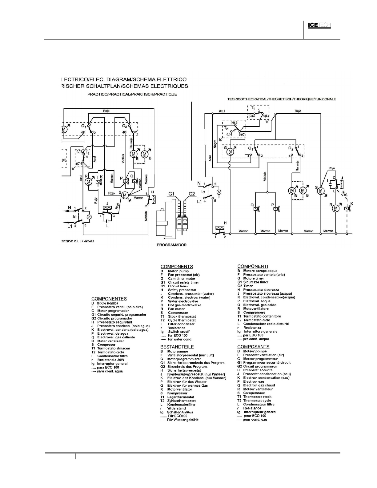
OPERATING PRINCIPLE FOLLOWING THE ELECTRIC DIAGRAM (TIMER ON DEFROST MICROSWITCHES DEPRESSED)
Current reaches the machine via the line connecting the blue (1) and brown (4) terminals. The
brown wire connects the compressor and timer motor. The blue wire connects bin thermostat T1

ICE TECH SS / SP Technical Service
Manual
5
which closes the circuit with 3. A different blue wire goes to 2 on terminal G1 which at this moment
is connecting 1 and 4. A red wire connects bin thermostat T1 and micros G1 and G2 which close
the circuit with 4 and provide current via G1 to the timer G.
At this point the following are connected:
• COMPRESSOR (S)
• WATER INLET VALVE (P)
• HOT GAS VALVE (Q)
• TIMER MOTOR (G)
After 2 to 4 minutes micros G1 and G2 will open and close circuits 1-2. Via terminal 2 on micro
G2, current reaches the pump. Circuit 4 on micro G2 which provides current to the hot gas valve
(Q) and water inlet valve (P) will be interrupted. Since the thermostat is between 1 and 3 the timer
will receive no current. The compressor continues switched on.
Air-cooled machines have a fan (R) which is controlled by the pressostat (F). In water-cooled
models without pressostatic valve, pressostat (J) opens and closes the condenser electrovalve
(K).
Evaporator temperature decreases until the cycle thermostat (T2) set point is reached, at this
temperature circuit 1-2 will be closed and timer motor (G) will switch on.
Once the cycle is over, the pins on the timer wheels will force the micros to change circuits,
stopping the pump and opening the hot gas valve and water valve. The combined effect of hot
gas and water sprayed on the top of the evaporator will release the ice cubes and change the
position of the cycle thermostat (T2).
The ice production and defrosting cycle will continue until the ice storage bin is full, at which point
cycle thermostat (T1) will disconnect the machine, but never during a cycle, but at the beginning
of the defrosting stage, since during the production cycle, current will reach the pump via terminals
1-2 of micro G1.
The machine will remain disconnected until the level of ice in the bin drops below the thermostat
because of ice consumption. At this point the machine will connect automatically.

ICE TECH SS / SP Technical Service
Manual
6
ICE TECH SS / SP Technical Service
Manual
7
1.4. Wiring diagram
ICE TECH SS / SP Technical Service
Manual
8
2. SPECIFICATIONS
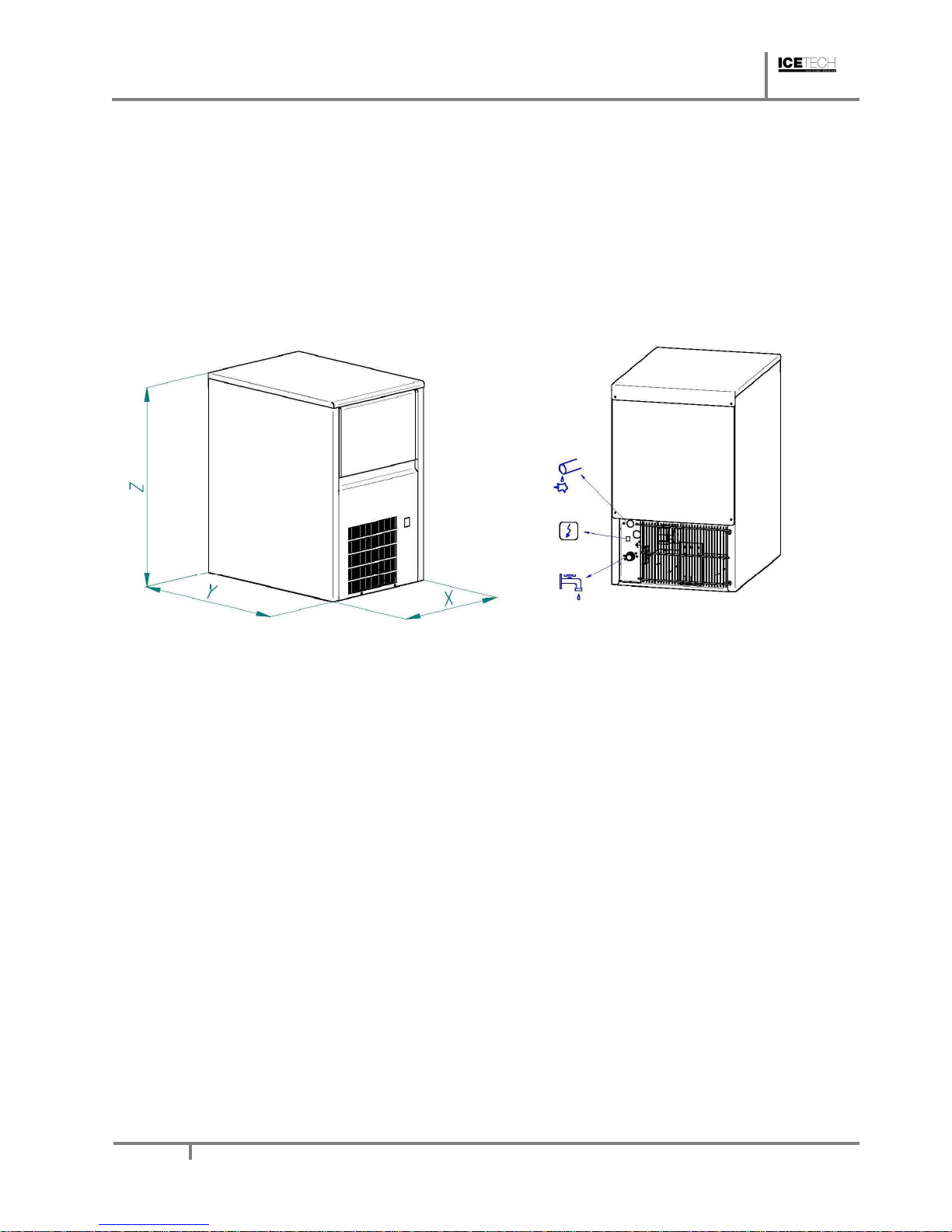
2.1. Installation diagrams for inlet/outlet tubes and dimensions
ICE TECH SS / SP Technical Service
Manual
9
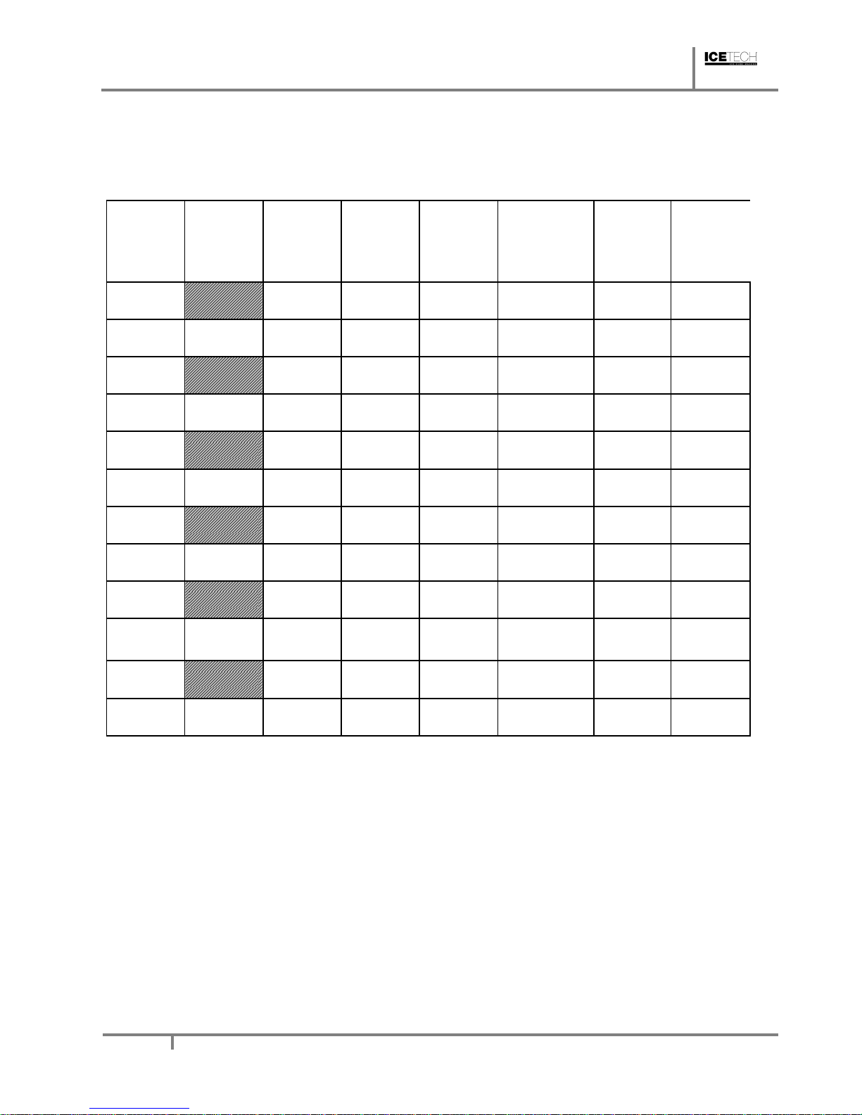
2.2. Consumption data, weights, crated dimensions and volumes
MODEL
WEIGHT
DIMENSIONS
WEIGHT
DIMENSION
WATER
COND.
WATER
TOTAL
NET
L/Hour
FABR.
L/Hour
L/Hour
(KG)
X*Y*Z
(KG)
(M3)
ICE TECH
25A
5.1 5.1 34 350x470x590 40 0.20
ICE TECH
25W
18 5.1 23.1 34 350x470x590 40 0.20
ICE TECH
35A
14 14 42 435x605x695 50 0.26
ICE TECH
35W
20 14 34 42 435x605x695 50 0.26
ICE TECH
45A
18.2 18.2 44 435x605x695 52 0.35
ICE TECH
45W
24 18.2 42.2 44 435x605x695 52 0.35
ICE TECH
60A
28.8 22.6 54 515x640x830 65 0.40
ICE TECH
60W
30 28.8 58.8 54 515x640x830 65 0.40
ICE TECH
80A
14.6 14.6 64 645x640x860 75 0.48
ICE TECH
80W
54 14.6 68.6 64 645x640x860 75 0.48
ICE TECH
135A
17.2 17.2 134 930x565x1050
145 0.63
ICE TECH
135W
59 17.2 76.2 134 930x565x1050
145 0.63
 Loading...