

Page 1

USER MANUAL
MANUAL DEL UTILIZADOR
MODELS / MODELOS
50C-CD 55
85C-CD 90
135C-GR 140
150
200/175-GR 220
400/355
550/475-GR 560
G550-GR 560S
1100
G110 0
Page 2

USER MANUAL
MANUAL DEL UTILIZADOR
Page 3

THIS MANUAL IS PART OF THE PRODUCT. READ IT CAREFULLY IN ORDER
TO USE AND MAINTAIN THE EQUIPMENT CORRECTLY. IT IS IMPORTANT TO
KEEP IT FOR FUTURE TROUBLESHOOTING AND REFERENCE.
WARNING
The installation of this equipment should be done by the Technical Assistance Service department.
The inlet jack should always be placed on an accessible location.
ALWAYS disconnect the power supply from the machine BEFORE any cleaning or maintenance service.
Any change needed on the electrical installation for the appropriate connection of the machine, should be
exclusively performed by qualied and certied professional personnel only.
Any use by the ice maker not intended to produce ice, using drinking water, is considered inappropriate.
It is extremely dangerous to modify or intend to modify this machine, and shall make any type warranty
void.
This machine should not be used by children or handicapped without the proper supervision and
monitoring.
Children should be monitored to assure that they should not play near the equipment.
This machine is not intended to be used outdoors nor exposed to the rain.
Connect the equipment to the drinking water network.
The machine should be connected using the power cable supplied with the equipment. The connection is
not intended for xed cabling.
ENGLISH
IT IS MANDATORY TO GROUND THE EQUIPMENT.
To avoid possible discharges on individuals or damages to the equipment, the
machine should be grounded pursuant local and/or national regulations as the
case may be.
THE MANUFACTURER SHALL BE HELD HARMLESS IN CASE OF DAMAGES
ARISING DUE TO THE LACK OF THE GROUND INSTALLATION.
In order to assure the proper operation and efciency of this equipment, it is of paramount importance to
follow the recommendations of the manufacturer, SPECIALLY THOSE RELATED TO CLEANING AND
MAINTENANCE OPERATIONS, which should be performed mostly by qualied personnel only.
CAUTION:
Do not try to perform repairs. The intervention of non-qualied personnel, besides of being dangerous,
could result in serious malfunctioning. In case of damages, contact your distributor. We recommend to
always use original replacement and spare parts.
Perform all discharge and recovery of materials or waste according the national regulations in force.
5
55
Page 4
ENGLISH
RECEPTION OF THE MACHINE
Inspect the outside packing. In case of damages, MAKE THE CORRESPONDING CLAIM TO THE
CARRIER.
To conrm the existence of damages, UNPACK THE MACHINE IN THE PRESENCE OF THE CARRIER and
state any damage on the equipment on the reception document, or on a separate instrument. As from May
1, 1998, we complie with the European regulations on management of packing and packing waste, inserting
the “Green Dot Label” on all their packages.
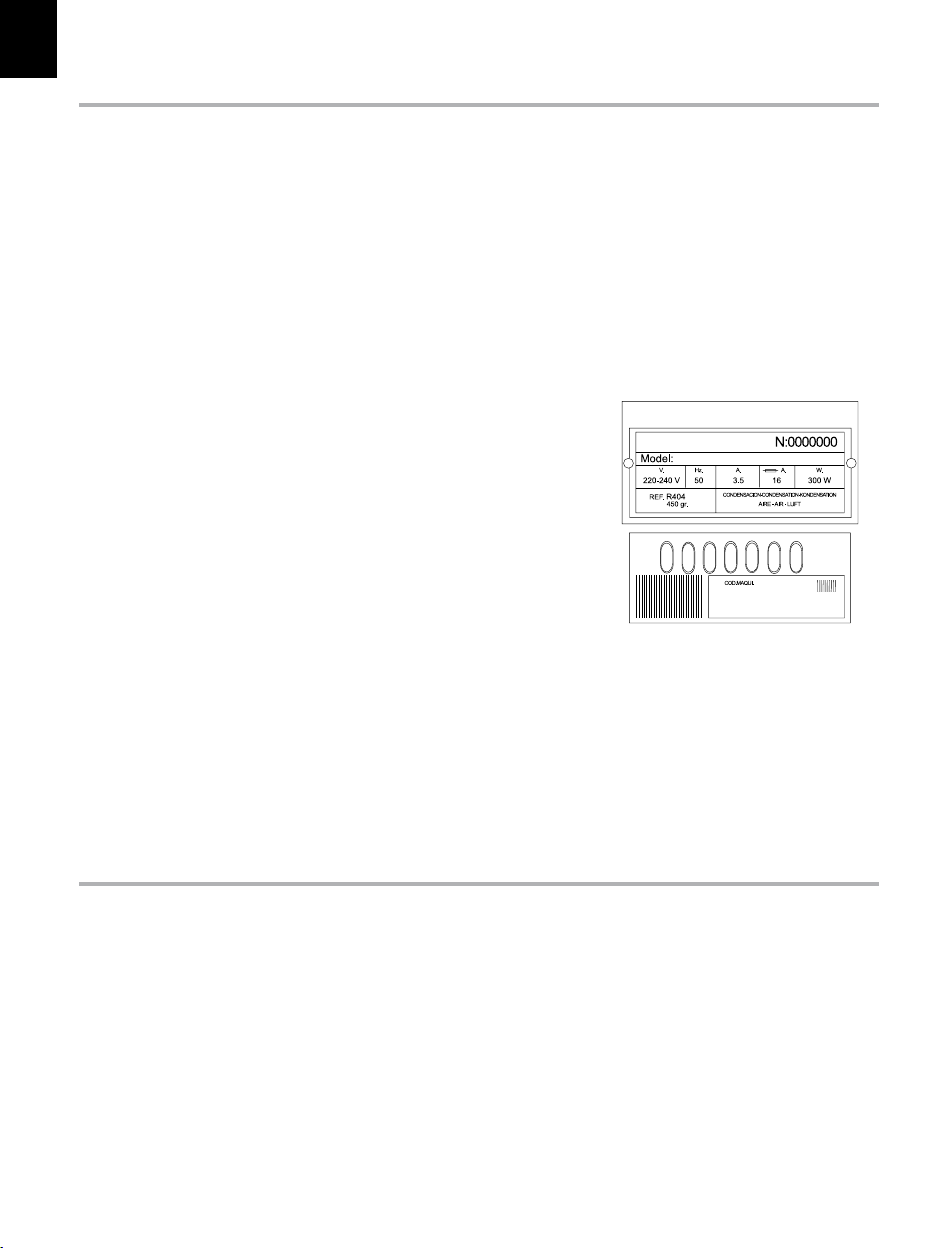
Always state the machine number and model. This number is printed on four locations:
1. PACKING
On the outside, it contains a label with the manufacturing number (1).
2. EXTERIOR OF THE EQUIPMENT
On the back of the equipment, there appears a label
with the same characteristics as the previous one (1).
3. NAMEPLATE
On the back of the machine.
Check that in interior of the machine the
installation kit is complete and comprises:
- Ice scraper, ¾ gas pipe, lters and manual.
- 22 mm drain hose in models 45 and 85
and in water cooled machines
- In some models, shims are included.
- Warranty and serial number.
(1)
CAUTION: ALL PACKING ELEMENTS (plastic bags, carton boxes and wood pallets)
SHOULD BE KEPT OUTSIDE THE REACH OF CHILDREN, AS THEY ARE A SOURCE
OF POTENTIAL HAZARD.
INSTALLATION
THIS ICE MAKER IS NOT DESIGNED FOR OUTDOOR OPERATION.
An incorrect installation of the equipment may cause damages to individuals, animals
or other materials, being the manufacturer not responsible for such damages.
CAUTION:
The machines are designed to operate at room temperature between 5ºC (41ºF) and 43ºC (109.40ºF), with
inlet water temperature between 5ºC (41ºF) and 35ºC (95ºF).
The reduction motor is excessively forced if operated under the minimum temperatures. Above the
maximum temperature, the life of the compressor is shortened and the production is substantially less.
Do not place anything over the maker or facing the front louver.
66
Page 5
In case the front louver is not enough, the exit is either total or partially obstructed or due to its placement
it will receive hot air from another device, we recommend, in case it is not possible to change the location
of the machine, TO INSTALL A WATER CONDENSER.
IT IS IMPORTANT THAT THE WATER PIPING DO NOT PASS BY OR NEAR SOURCES
OF HEAT SO AS NOT TO LOSE ICE PRODUCTION.
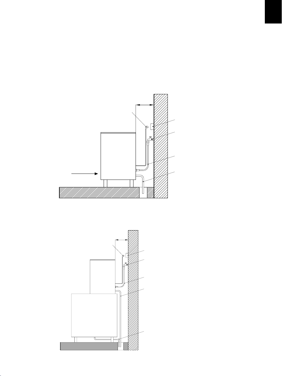
THREAD THE SUPPORT LEGS TO THE BASE OF THE MACHINE ON THE
HOUSING SET TO SUCH END AND REGULATE THE HEIGHT AS TO HAVE THE
EQUIPMENT PERFECTLY LEVELED.
>4''
>10 cm
Jack
Base jack
Bib
Water connection hose
ENGLISH
Ventilation louver
IN MODULAR MACHINES
Jack
>4''
>10 cm
Discharge hose
Base jack
Bib
Water connection hose
Condenser discharge outlet
Silo drainage
7
7
Page 6
ENGLISH
1. WATER AND DRAINAGE
Water quality has a remarkable inuence on the appearance,
hardness and avor of the ice as well as, on the machines
condensated by water, on the life of the condenser.
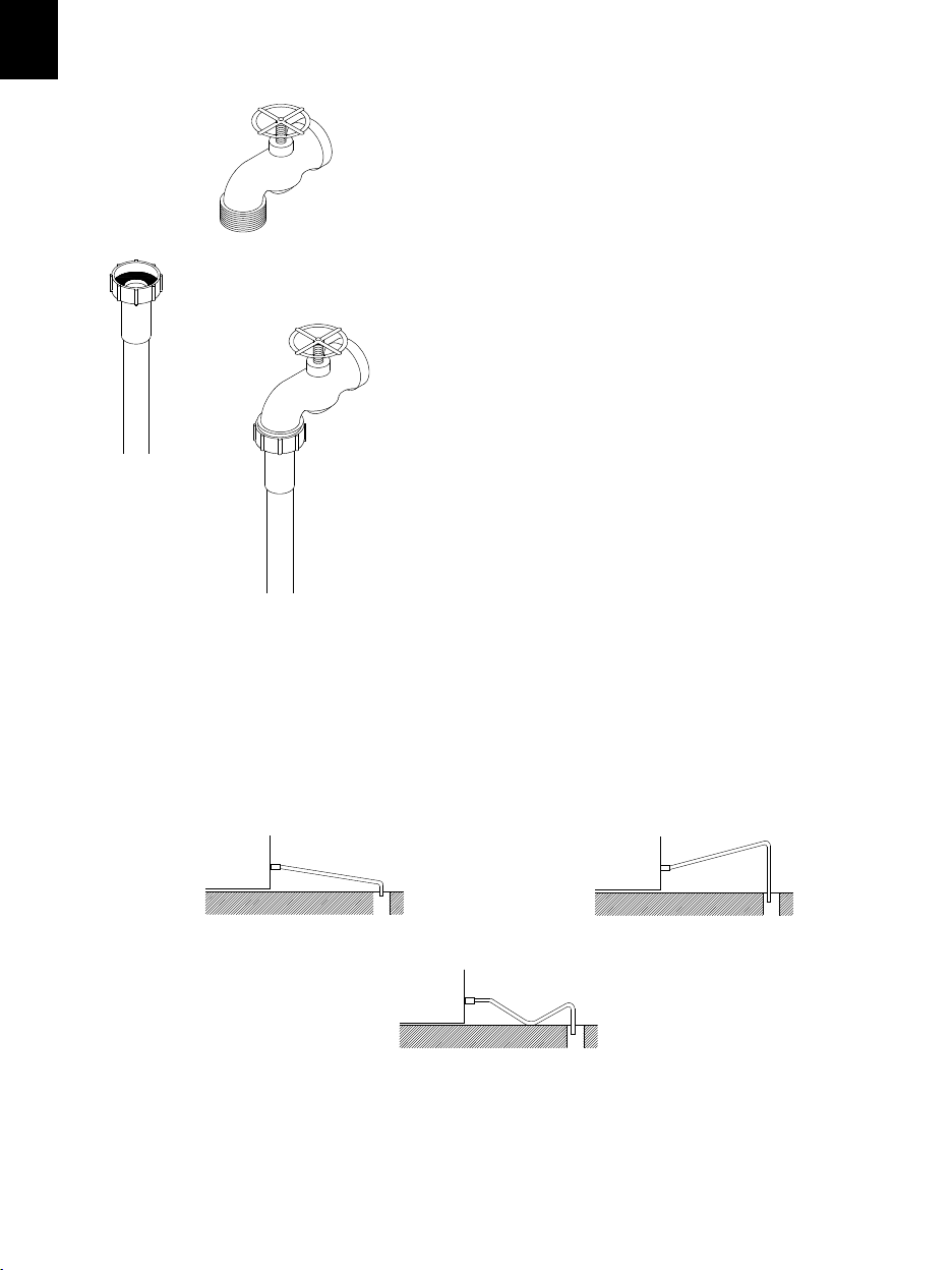
2. CONNECTIONS TO THE WATER
NETWORK
Use a exible pipe (1.3 m – 4.27 feet length) with the two lter
joints supplied with the machine. We strongly discourage the
use of two-exit bibs and two switches as, due to an error
could close that back one, leaving the machine without water
supply. This could result on a damage call without actually
existing one.
Pressure should be established between 0.7 and 6 Bar (10 /
85 psi.)
If pressures overpass such values, install the necessary
corrective devices.
INSTALL A 10 µ PARTICLE FILTER INCLUDED IN THE
KI T.
3. CONNECTION TO DRAINAGE
Drainage should be located lower to the machine level, at 150 mm (5.91 inches) minimum.
It is convenient that the drainage pipe is of 30 mm (1.18 in) of interior diameter and with a
minimum gradient of 3 cm (1.18 in) per meter (see gure).
CORRECT INCORRECT
Descending
INCORRECT
8
Ascending
Page 7
4. ELECTRICAL CONNECTION
IT IS MANDATORY TO GROUND THE EQUIPMENT.
To avoid possible discharges on individuals or damages to the equipment, the
machine should be grounded pursuant local and/or national regulations as the
case may be.
THE MANUFACTURER SHALL BE HELD HARMLESS IN CASE OF DAMAGES
ARISING DUE TO THE LACK OF THE GROUND INSTALLATION.
The machine is supplied with a 1.5 m (4.92 feet) cable of length. In case the supply cable is damaged, it should
be replaced by a cable of special assembly to be furnished by the manufacturer or post-sale service. Such
replacement should be performed by qualied technical service only.
The machine should be places in such a way as to allow a minimum space between the back and the wall to
allow an easy access and without risks to the cable jack.
Safeguard the base of the jack.
It is convenient to install adequate switches and fuses.
The line up to the jack should have a minimum section of 2.5 mm2 (0.0038 in2)
Voltage and tension are indicated in the nameplate and on the technical specications
of this manual. Variation on voltage above the 10% stated on the nameplate could
result on damages or prevent the machine start-up.
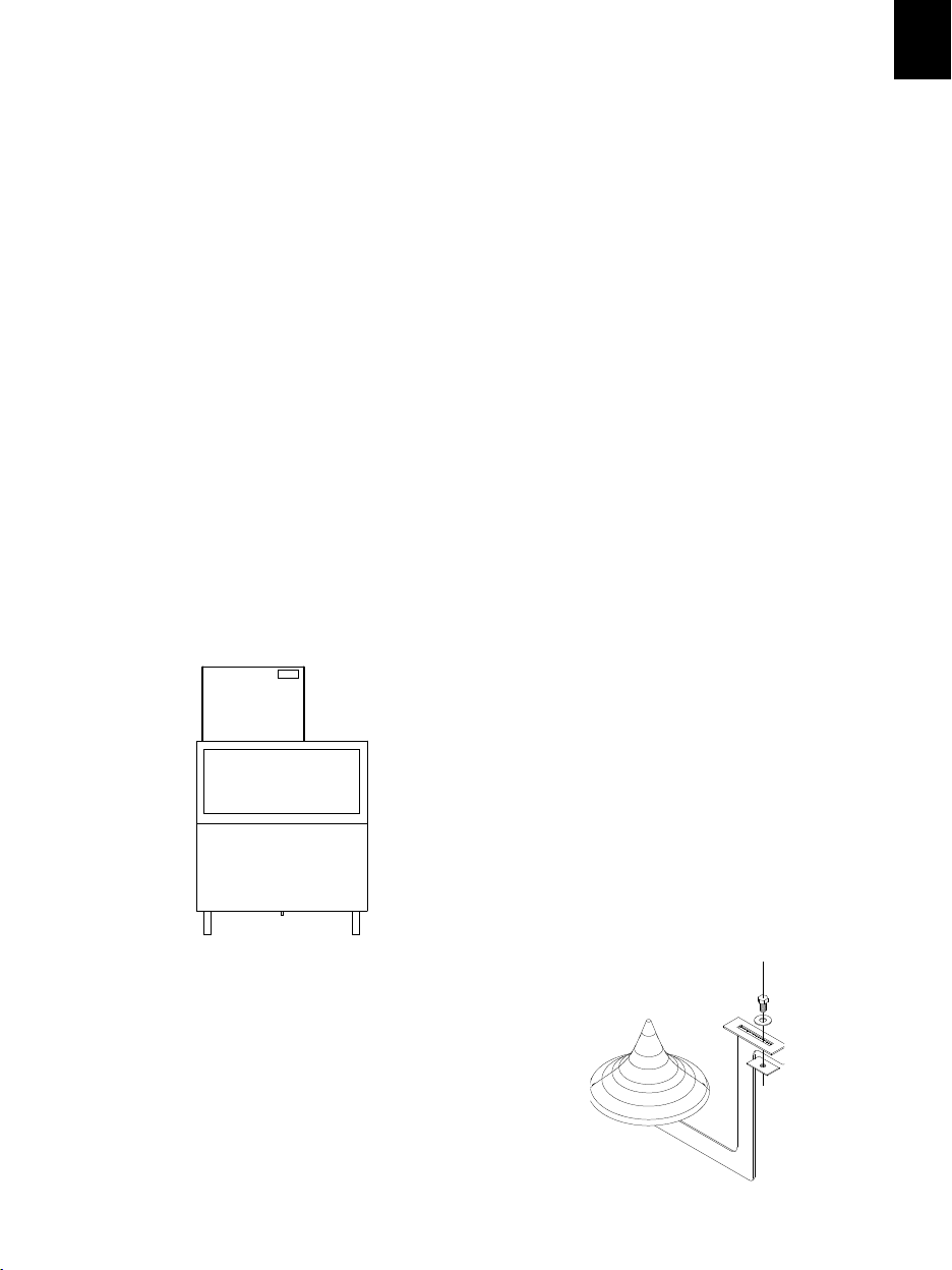
5. INSTALLATION OF MODULAR EQUIPMENTS OVER DEPOSITS OR SILOS
ENGLISH
Modular makers should be installed over deposits
or silos, following the instructions contained in this
manual.
The resistance and stability of the
container-machine/s assembly should be veried,
as well as the fastening elements.
6. ASSEMBLY OF THE DISPERSION CONE
(MODULAR MODELS)
This device distributes the ice in the silos, and
avoids ice compression under the exit pipe.
Changing its position, the ice could be directed to
any direction.
9
Page 8
ENGLISH
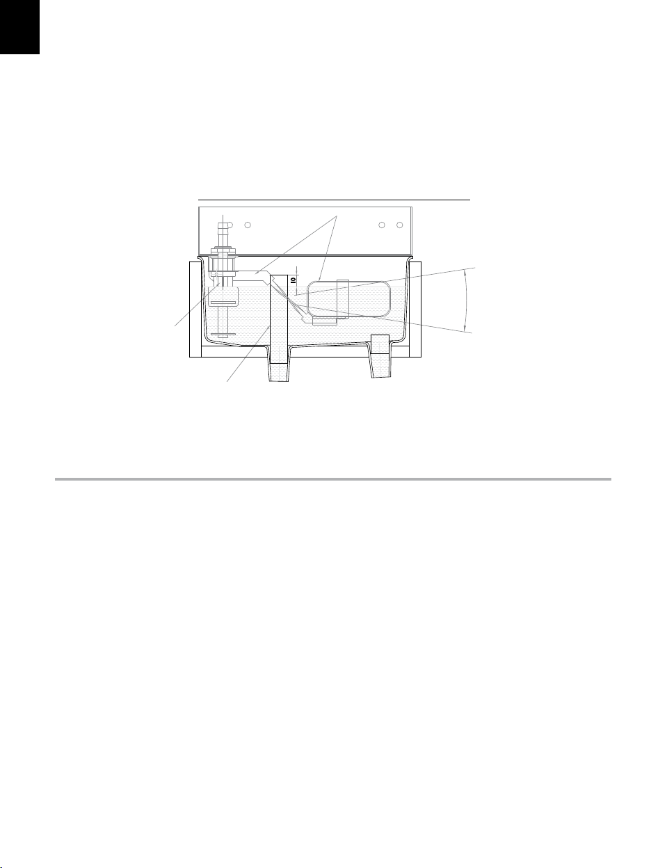
7. WATER LEVEL
The function of the water level is to maintain the necessary ow on the evaporator, and using the magnetic
micro device incorporated, stop the operation of the machine until the water reaches again the container.
The models 400, 550 and 1100 have a water pressostat replacing the micro-magnetic.
The optimum level is located on the horizontal indicated in the gure, and its regulation is made following
the indications appearing below.
FLOAT VALVE REGULATION
FL OAT
PROBE
SAFETY OVERFILL
Turn upwards to increase the level,
and down wards to d ecrea se it.
(Grab from the me tallic a rm, NE VER
FROM TH E FLOAT)
START-UP
1. Previous Checkup
a) Is the machine leveled?
b) Voltage and frequency are the same as those on the nameplate?
c) Are the discharges connected and operating?
d) ** If air condensed: Is the air circulation and its temperature appropriate?
RO OM WATER
MAXIMUM 43ºC / 109,40ºF 35ºC / 95ºF
MINIMUM 5ºC / 41ºF 5ºC / 41ºF
e) ** Is water pressure appropriate?
MINIMUM 0,7 Bar (10 psi)
MAXIMUM 6 Bar (85 psi)
NOTE: In case input water pressure is higher that 6 Bar (85 psi), install a pressure reducer. THE BIBB
CONNECTION PRESSURE SHOULD NEVER BE REDUCED.
10
Page 9

2. Start-up
Once the installation instructions are followed (ventilation, site conditions, temperatures, water quality,
etc.), proceed as follows:
1. In the case of modular modules, remove the cover to access the installation kit (lters, connection hoses,
dispersion cones, etc.).
2. In case of compact models, open the deposit door to access the installation kit.
3. Open the water inlet. Verify the existence of leakages.
4. Connect the machine to the electrical network.
5. Verify that there are no vibrations or frictions on the elements.
6. After the 10 minutes of the timer installed in the electric panel, the machine will start the operation.
7. In the case of modular models (mainly in three-phase equipments), having the cover removed, verify that
the motor is rotating in the correct direction.
8. Verify that after 15 minutes, the frost on the aspiration pipe is at 20 mm (0.78 in) of the compressor.
CAUTION:
INSTRUCT THE USER ABOUT MAINTENANCE, INFORMING THAT
MAINTENANCE AND CLEANING OPERATION AS WELL AS DAMAGES
DUE TO THE LACK OF SUCH OPERATIONS: ARE NOT INCLUDED ON THE
WARRANTY.
The technical installer shall invoice traveling costs, hours and materials used on such operations.
ENGLISH
MAINTENANCE AND CLEANING INSTRUCTIONS
CAUTION: Maintenance and cleaning operations and damages as the lack of those activities: Are not
included on the warranty.
If a good maintenance is performed, the machine will continue producing a good quality ice and will be free
of damages.
Maintenance and cleaning intervals will depend on the conditions of the location and water quality.
CAUTION: At least, one revision and cleaning should be performed every six months.
On dusty environments, it might be necessary to clean the condenser on a monthly basis.
MAINTENANCE AND CLEANING PROCEDURES:
** CAUTION: For all cleaning and maintenance operations: Disconnect the machine from the power
supply.
11
Page 10

ENGLISH
1. Water condenser
1. Disconnect the machine.
2. Disconnect the water inlet or close the bibb.
3. Disconnect the water inlet and outlet from the condenser.
4. Prepare a solution at the 50% of phosphoric acid and distilled or demineralized water.
5. Make the solution circulate through the condenser. (The solution is more effective if hot – between 35ºC
[95ºF] and 40ºC [104ºF]).
DO NOT USE HYDROCHLORIC ACID.
2. Air Condenser
1. Disconnect the machine.
2. Disconnect the water inlet or close the bibb.
3. Clean the louvered area with the help of an aspirator with a brush, non-metallic brush or low-pressure
ai r.
3. Cleaning the Stock Container (Compact models)
1. Disconnect the machine, close the water and empty the ice-cube stock.
2. Use a dishcloth and bleach with detergent.
4. Exterior Cleaning
Use the same procedure as the one indicated for the container.
5. Cleaning of the Inlet Filters
They are easily obstructed during the rst days of operation, MAINLY WITH NEW PIPING
INSTALLATIONS.
Loose the hose and clean it under water.
6. Water Leak Control
When working on the machine, always check the water connections, status of the clamps and hoses with
the purpose of avoiding leakages and prevent damages or oods.
12
Page 11

PANELES DE CONTROL / CONTROL PANEL
1. MODELO 45-CD50 / MODEL 45-CD50
Piloto verde: Indica que la máquina está activada. Puede estar parada por termostato de stock.
Pulsador negro: Pone la máquina en funcionamiento. También rearma la máquina cuando está parada por
algún elemento de seguridad.
Pulsador rojo: Para la máquina completamente.
Green Led: Indicates that the machine is activated. Might be stopped due to the bin thermostat
Black Switch: Starts the operation of the machine. Also rearms the machine when it is stopped by some
security element.
Red Switch: Stops the machine completely
Pilot o verde
Green Led
Pulsador negro
Black Switch
Pulsador rojo
Red Switch
2. MODELO 85-CD90 / MODEL 85-CD90
Pulsador verde: Pone la máquina en funcionamiento indicándonoslo con el piloto encendido.
Piloto rojo: Nos indica que la máquina está parada por algún elemento de seguridad
Piloto naranja: Nos indica cuando el almacén de hielo está lleno.
Green Switch: Starts the operation of the machine. It is indicated with the led on.
Red Led: Indicates that the machine is stopped by a security element.
Orange Led: Indicates that the storage bin is full of ice.
Piloto naranja
Orange Led
Piloto rojo
Red Led
Pulsador verde
Green Switch
133
Page 12

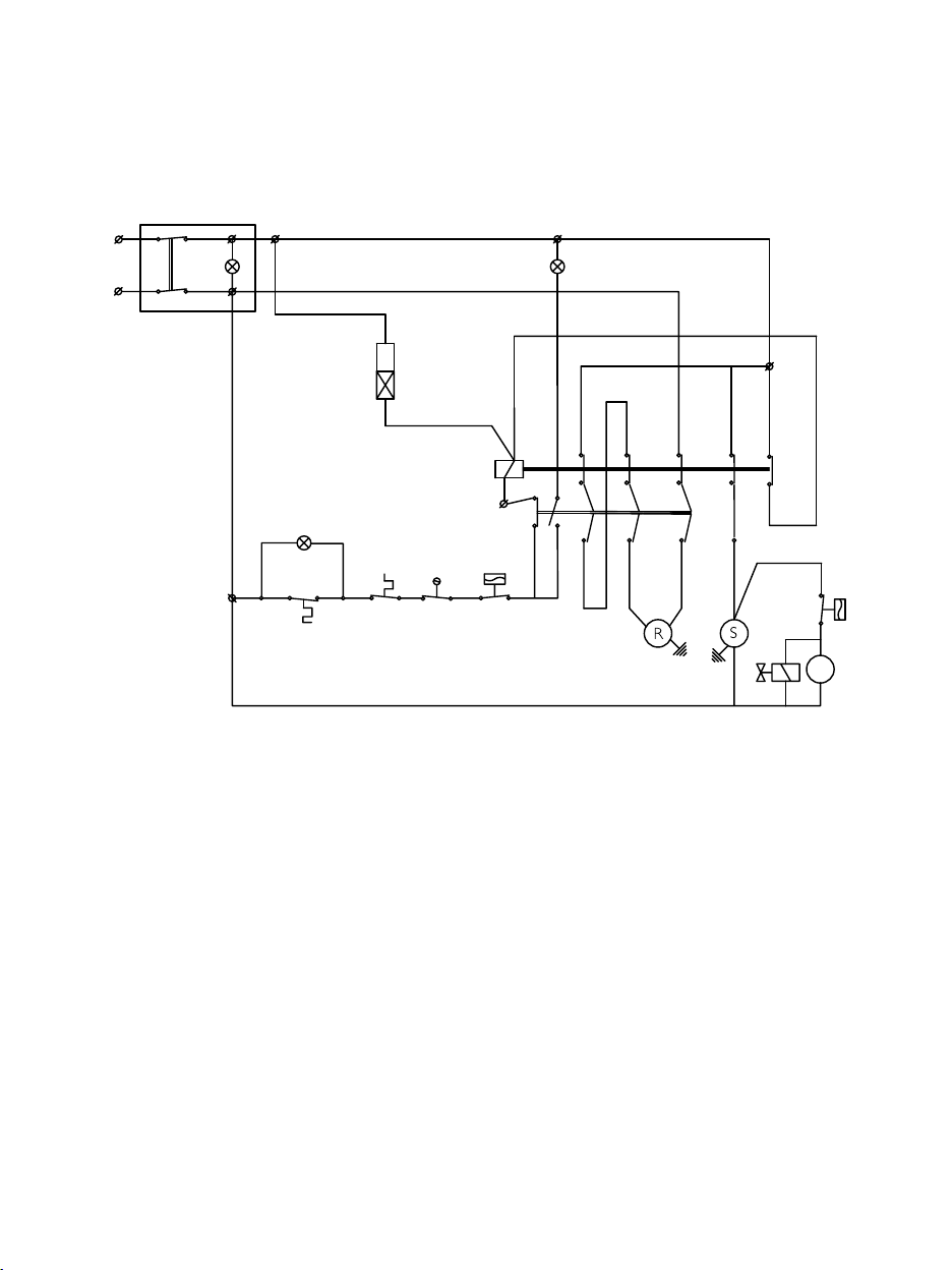
ESQUEMAS ELéCTRICOS / WIRING DIAGRAM
45-CD50
Ps
L
Marrón/Brown
K
N
-Presostato ventilador
Pv.
-Ventilador
V.
-Electroválvula condensaciónEw.
-Compresor
S.
-Interruptor de marcha
Ir.
-Interruptor de paroIs.
-Paro por llenado
Ts.
-Micro boya falta de agua
Iw.
Ps.
-Presostato de seguridad
-Motorreductor
R.
Pt.- Protector térmico motor
-LED Verde linea
K
Ir
Is
Pt
Iw
Negro/Black
(1)
9
Rojo/Red
Pv
Ts
R S
58
L
C
(2)
V
Ew
Azul/Blue
-Fan pressostat
Pv.
-Fan
V.
-Condenser water valveEw.
-Compressor
S.
-On switch
Ir.
-Off switchIs.
-Full storage bin stop
Ts.
-Water low level float switch
Iw.
Ps.
-High pressure safety pressostat
-GearmotorR.
-Motor thermal protectionPt.
K- LED Green on
13
14
Gris/Grey
Violeta/Violet
12
26/05/2008 plano: 24/10
134
Page 13
85-CD90
N
L
Ip
Azul/Blue
IIII
Marrón/brown
A
1
Tem.
L
A
2
2
L
1
Violeta/Violet
Violeta/Violet
L
98
97
T
1
Gris/Grey
Gris/Grey
A
1
c
1
Marrón/brown
II
Pt
Violeta/Violet
Ts
A
2
96
95
Ps
Iw
L
C
3
4
LL
22
T
T
2
3
Rojo/red
Marrón/brown
Negro/Black
3
a1
C
4
L
Pv
C
(2)
V
Ew
Tem.
-Contactor
C
1
-Presostato ventilador (sólo cond.por aire)Pv.
-VentiladorV.
-Compresor
S.
-Interruptor de paro-marchaIp.
-Paro por llenado
Ts.
-Micro boya falta de aguaIw.
-Presostato de seguridad
Ps.
-Motoreductor
R.
Pt.- Protector térmico motor
-Electroválvula condensaciónEw.
04/10/2010 plano:24/10
Tem.
-Start timer-Temporizador a la conexion
-Contactor
C1
-Fan pressostat (only air cooled models)
Pv.
V. -Fan
-Compressor
S.
Ip.
-On/off switch
Ts.
-Full storage bin stop
Iw.- Water low level float switch
Ps.
-High pressure safety pressostat
R. -Gearmotor
Pt.
-Motor thermal protection
-Condenser water valveEw.
III-Verde linea / Green on
-Ambar llenado/ Yellow full
III
-Termico Motorreductor/Thermic gearmotor
135
Page 14

MONOFÁSICA / MONOPHASE
N
Azul/Blue
Azul/Blue
A
Negro/Black
Negro/Black
1
1
L
2
L
3
L
Azul/Blue
A
1
Azul/Blue
L1
Tem.
A
2
Ps
Marrón/Brown
A
2
CL
C
c
1
Rojo/Red
1
T
c
2
2
T
c
3
T
3
T1T
Rojo/Red
Rojo
Agua
Iw-Pw
Dis.
21
LL
2
(1)
R
S
Red
Water
3
L
3
T
Violeta/Violet
Ambar
Llenado
Yellow
Full
Gris/
Grey
St
4
Blanco/
2
1
White
Pt
Marrón/Brown
Rojo
/Red
Marrón/Brown
2
Azul
linea
Blue
on
Disyuntor
Breaker
1
Marrón/Brown
Ip
45
(1)SÓLO EN LA IQ550-GR560S / ONLY IQ550-GR560S
Tem.
-Temporizador a la conexion
-Contactor
C.
c
-Contacto (Motorreductor)
1
c
-Contacto (Compresor)
2
c.
-Contacto autoalimentacion
3
Dis.
-Disyuntor (Motorreductor)
Pv.
-Presostato ventilador (solo cond.por aire)
-Ventilador
V.
-Compresor
S.
Ip.
-Interruptor de paro-marcha
St.
-Paro por llenado
Iw.
-Micro boya falta de agua
Pw.
-Presostato de agua (IQ400/550-GR560S)
-Presostato de seguridadPs.
R.
-Motoreductor
-Protector térmico motor
Pt.
01/02/2011 plano: 24/10
Pv
V
Tem.
-Start timer
C.
-Contactor
c1-contact (gearmotor)
c
-Contact (Compressor)
2
c.
-Feedback contact
3
-Circuit Breaker (motorgear)
Dis.
-Fan pressostat (only air cooled models)
Pv.
V.
-Fan
S.
-Compressor
Ip.
-On/off switch
St.
-Full storage bin stop
Iw.
-Water low level float switch
-Water pressostat (IQ400/550-GR560S)
Pw.
Ps.
-High pressure safety pressostat
R.
-Gearmotor
-Motor thermal protectionPt.
136
C
L
Page 15

400/550-GR560 R404A TRIFÁSICA / 400/550-GR560 R404A TRIPHASE
Pv
3.6 A
OVERLOAD SETTING
REGULACION TERMICOS
COMPRESOR
COMPRESSOR
II
Rojo/Red
V
Rojo/Red
C
L
V
L
a2
C
63/NO
14/22
3
L
2
L
1
L
2
A
2
c
3
T
Negro/Black
2
T
1
T
98
97
95
96
1
A
R
Negro/Black
Marrón/Brown
1.3 A
MOTORREDUCTOR
GEARMOTOR
01/02/2011
Marrón/Brown
R
Negro/Black
STN
11
T
SR
DF
Ps
Red
Water
(1)
Iw-Pw
Agua
Rojo
Negro/Black
Azul/Blue
IV
Gris/Grey
4
St
21
III
Ip
Pt
14 12
-Termico compresor/Thermic compressor
-Detector de fase/Phase sequence relay
-Contacto auxiliar autoalimentacion/Auxiliar contact feedback
-Protector térmico motor/Motor thermal protection
-Motoreductor/Gearmotor
-Condensador filtro/Electrical interference filter (capacitador)
DF.1CaIPt.
R.
L.
a1
C
63/NO
14/22
3
L
2
L
1
L
Violeta/Violet
2
L
Marrón/Brown
A
1
c
1
A
2
A
3
T
Negro/Black
2
T
1
T
98
97
95
96
1
A
S
Negro/Black
Marrón/Brown
-Contacto auxiliar autoalimentacion/Auxiliar contact feedback
2
Ca
-Termico Motorreductor/Thermic gearmotor
IIIVIII
-Ambar llenado/ Yellow full
-Azul linea / Blue on
-Fase cambia/Phase sequence
V
Tem.
Violeta/Violet
2
1 C
I
54
Rojo/Red
Marrón/Brown
Marrón/Brown
-Temporizador a la conexion/Start Timer
Tem.
-Compresor/Compressor
-Interruptor de paro-marcha/On-off switch
-Paro por llenado/Full storage bin stop
-Presostato ventilador (sólo cond.por aire)/Fan Pressostat (only air cooled models)
-Contactor (Motorreductor)/Contact (Gearnotor)
-Contactor (Compresor)/Contact (Compressor)
1
c
-Ventilador/Fan
V.2cS.Pv.
Ip.
St.
-Micro boya falta de agua/Water low level float switch
-Presostato de seguridad/High pressure safety pressostat
Pw.- Presostato de agua/Water pressostat
Iw.
Ps.
137
Page 16

GENERADOR 550-GR560S / GENERATOR 550-GR560S
R
S
T
Marrón/Brown
Negro/Black
Negro/Black
RDFS14T
11
12
Rojo/Red
Pt
1
4
A
1
2
L
3
A
2
c
1
A
1
95
96
L
97
98
T
3
Negro/Black
Marrón/Brown
1
L
T
T
2
1
Negro/Black
63/NO
14/22
T1
a1
C
A
2
5
1
2
Violeta/Violet
Iw-Pw
Ip
2
I
St
Gris/Grey
4
II
V
III
R
Verde/Green
15
A
1
T2
18
A
2
IV
SL
N
Azul/Blue
T1
-Temporizador a la conexion / Start timer
T2
-Temporizador retardo solenoide / liquid valve timer
c
1
-Contactor (Motorreductor) / Contact (gearmotor)
SL.
-Solenoide de líquido / Liquid valve
Ip.
-Interruptor de paro-marcha / On-off switch
-Paro por llenado / Full storage bin stop
St.
-Micro boya falta de agua / Water low level float switch
Iw.
Pw.- Presostato de agua / Water pressostat
01/02/2011 plano: 24/10
138
R.
-Motoreductor / Gearmotor
Pt.
-Protector térmico motor / Motor thermal protection
DF.
-Detector de fase / Phase sequence relay
1
Ca
-Contacto auxiliar motorreductor / Auxiliar contact gearmotor
I
-Azul linea / Blue on
II
-Ambar llenado / Yellow full
-Fase cambia / Phase sequence
III
-Termico Motorreductor / Thermic gearmotor
IV
V
-Rojo: agua / Red: Water
Page 17

1100 R404A TRIFÁSICA / 1100 R404A TRIPHASE
Rojo/Red
Marron/Brown
Azul/Blue
Negro/Black
N
TSR
1
3
4
Ca
3
L
2
L
1
L
1
2
A
A
1
A
1
c
Tem.
3
T
Rojo/Red
T
Rojo/Red
S
1 2
T
Rojo/Red
98
97
95
96
2
A
V
1
14
11
T
Marron/Brown
12
1
Iw
R S
DF
IV
IV
1
Ca
3
4
3
L
2
L
1
L
98
97
2
1
A
A
Tem.
95
96
2
1
A
A
1
c
St
Gris/Grey
3
T
2
T
1
T
I
2
Violeta/Violet
1
Rojo/Red
Rojo/Red
Rojo/Red
2
St
2
Gris/Grey
S
2
4
3
Ca
3
L
2
L
1
L
97
95
2
1
A
A
2
c
III
L C
Ps
Marron/
Brown
CL
Ps
III
2
Ca
3
4
3
L
2
L
1
L
97
95
2
1
A
A
2
c
II
Pv
L
L
3
T
2
T
1
T
98
96
White
Blanco/
Violeta/Violet
White
Blanco/
Pv
L
L
3
T
2
T
1
T
98
96
3.6 A
1.3 A
C
15-09-08
V
OVERLOAD SETTING
REGULACION TERMICOS
MOTORREDUCTOR /
GEARMOTOR
COMPRESOR /
Negro/Black
Negro/Black
R
COMPRESSOR
Negro/Black
Pt
Marron/
Ip
Ip
Brown
1 -Contacto auxiliar motorreductor / Auxiliar contact gearmotor
Ca2 -Contacto auxiliar autoalimentación / Auxiliar contact feedback
I -Térmico compresor / Thermic compressor
II -Térmico motorreductor / Thermic gearmotor
III -Verde línea / Green on
IV -Ambar llenado / Yellow full
L. -Condensador filtro / Electrical interference filter (capacitador)
Pt. -Protector térmico motor / Motor thermal protection
DF. -Detector de fase / Phase sequence relay
Ca
V -Fase cambia / Phase sequence
Marron/Brown
II
C
V
Negro/Black
R
Negro/Black
Negro/Black
Pt
c2 -Contactor (compresor) / Contact (compressor)
Pv. -Presostato ventilador (solo cond.por aire) / Fan pressostat (only air cooled)
V. -Ventilador / Fan
S. -Compresor / Compressor
Ip. -Interruptor de paro-marcha / On-off switch
St. -Paro por llenado / Full storage bin stop
Iw. -Presostato falta de agua / Water low pressure switch
Ps. -Presostato de seguridad / High pressure safety pressostat
Tem. -Temporizador a la conexion / Start timer
c1 -Contactor (motorreductor) / Contact (gearmotor)
R. -Motorreductor / Gearmotor
139
Page 18

GENERADOR 1100 / GENERATOR 1100
Marron/Brown
Negro/Black
R
Negro/Black
S
Ip
1
T1
A
Violeta/
Violet
Iw
V
T1
3
1
L
2
L
3
L
2
A
Pt
I
2
A
a1
C
4
Black
1
T
Negro/
2
Black
T
R
Negro/
Brown
3
T
Marron/
98
97
95
96
1
A
1
c
15
1
Azul/Blue
IV
18
2
ASLA
13-12-08
T2
III
1 -Contacto auxiliar motorreductor / Auxiliar contact gearmotor
I -Verde línea / Green on
II -Ambar llenado / Yellow full
III -Fase cambia / Phase sequence
IV -Térmico motorreductor/ Thermic gearmotor
V -Agua / Water
DF. -Detector de fase / Phase sequence relay
IIII
14
11
TS
12
R
Gris/Grey
Gris/Grey
4
4
St
Blanco/
White
St
2
1
2
1
Ca
DF
Ip
1
A
Violeta/
Violet
Iw
V
T1
3
1
L
2
L
3
L
2
A
Pt
T
I
2
A
a1
C
4
Black
1
T
Negro/
2
Black
T
Negro/
R
Brown
3
T
Marron/
98
97
95
96
1
A
1
c
15
1
ASLA
Azul/Blue
IV
18
2
T1 -Temporizador a la conexion / Start timer
T2 -Temporizador válvula líquido / Liquid valve timer
Pt -Protector térmico motor / Motor thermal protection
Ip. -Interruptor de paro-marcha / On-off switch
St. -Paro por llenado / Full storage bin stop
Iw. -Micro boya falta de agua / Water low level float switch
R. -Motorreductor / Gearmotor
T2
N
140
Page 19

141
Page 20

142
Page 21

NOTAS / NOTES
Page 22

C/1866 - 14/J/13
 Loading...