

Page 1
PRODUCT MANUAL FOR MODEL
IOD16022 AND IOD22030
COUNTER TOP DISPENSER
Part Number 9081286-01 Print Date 7/01P
Page 2

IOD16022
Introduction IOD22030
To the owner or user: This product manual is a source of information about the installation, start up,
cleaning, maintenance and repair of the product.
The IOD16022 and IOD22030 are ice only counter top dispensers designed to use 22 inch wide and
30 inch wide respectfully Ice-O-Matic cubed ice machines as the source of ice.
Ice from the cuber falls into the insulated bin where it is stored until needed. When a user pushes the
dispense button, a rotating wheel scoops the ice up to the top front of the bin where there is an outlet
to the ice chute. Ice will dispense continually for as long as the push button or lever is depressed or
until the bin is empty.
Table of Contents
Specification/Limitations Page 2-3
Installation Page 4-7
Cleaning Page 8-9
Service Diagnosis Page 10
Parts List Page 11-19
Wiring Diagram Page 20-21
Warranty Information Page 3
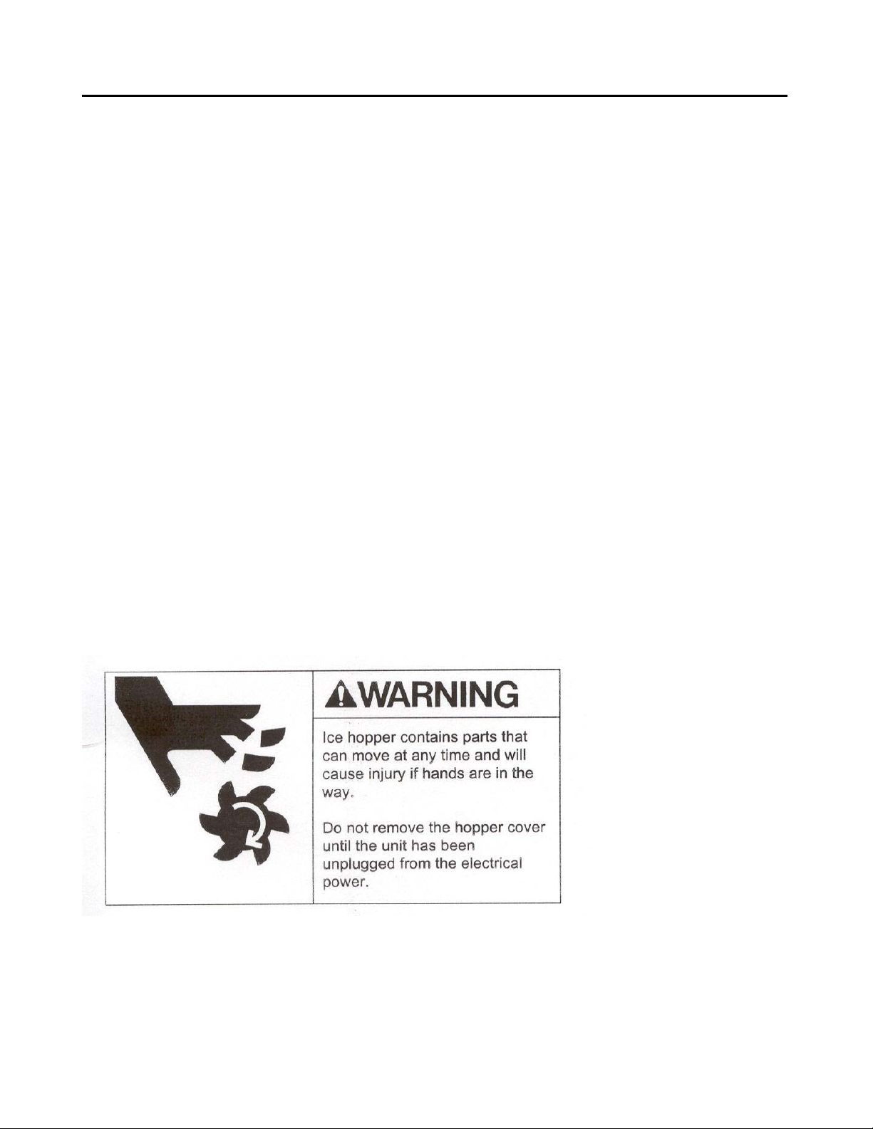
Note the warning symbol where it appears in this manual.
It is an alert for important safety information on a hazard
that might cause serious injury.
Keep this manual for future reference.
Page 1
Page 3

IOD16022
Specifications IOD22030
Limitations:
Must meet the same limitations as the cuber installed on top of it:
50° F. air minimum
100° F. air maximum
Must be installed indoors.
Must allow at least 6 inch clearance at the rear and both sides when using an air cooled ice
machine.
Must allow space for the utility connection at the back.
Must have a drain.
Options (Field Installed) ( *Required )
*Thermostatic Bin Control Kit (22 Inch Ice Series) Part Number 1051134-01
*Thermostatic Bin Control Kit (30 Inch Ice Series) Part Number 1051020-02
Manual Water Glass Filler Kit Part Number KISWGF
Ice Machine Adapters
*22 inch cuber Part Number KBT2222
*30 inch cuber Part Number KBT3030
*22 inch machine on a 30 inch dispenser Part Number KBT2230
Leg Kit Part Number KIOD4
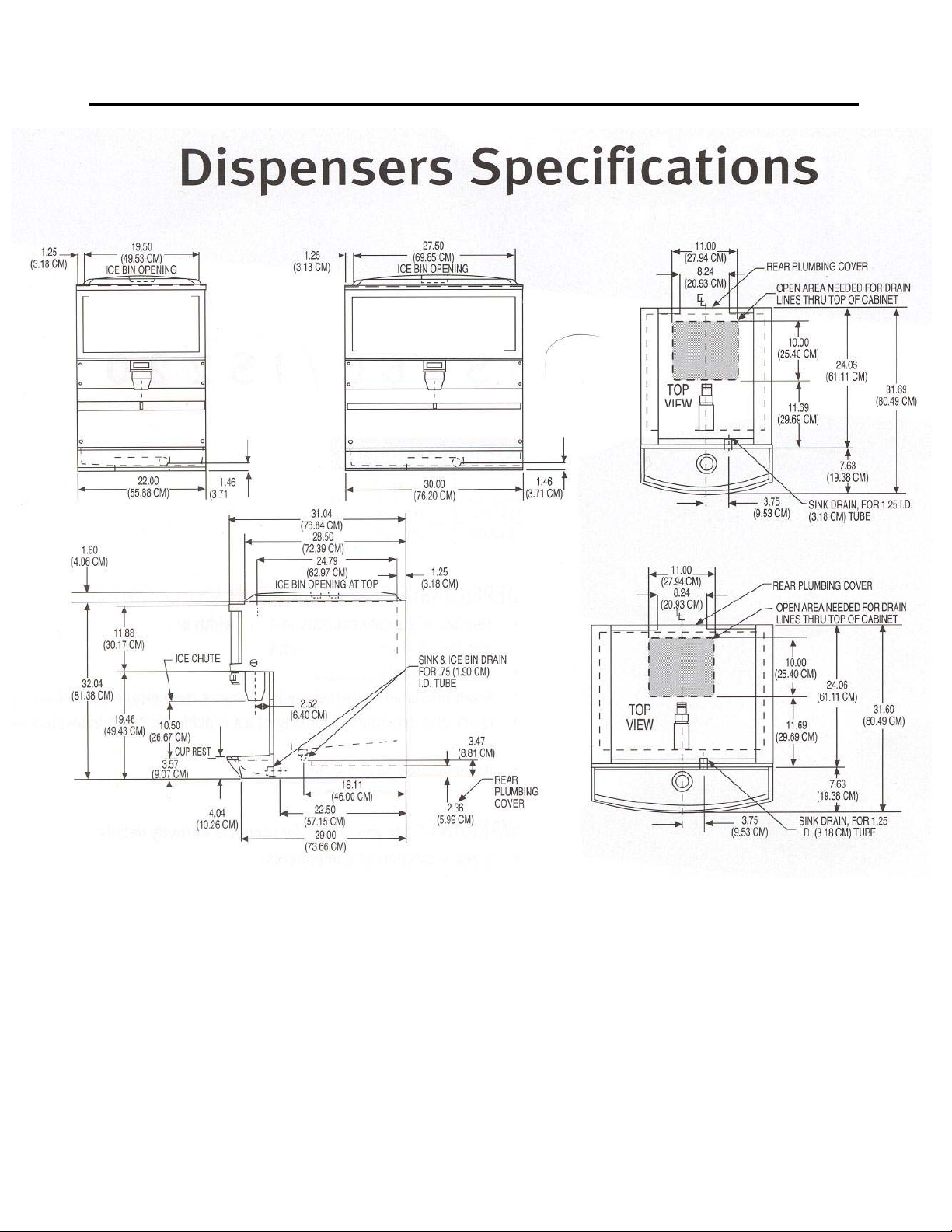
Dispenser Specifications
Storage Basic Min. Circuit
Model Number Capacity(lbs-kgs) Electrical Actuation Ampacity Max. Fuse Size
IOD16022 160/70 115/60/1 Lever 2 15
IOD16022 160/70 115/60/1 Button 2 15
IOD22030 220/100 115/60/1 Lever 2 15
IOD22030 220/100 115/60/1 Button 2 15
Dimensions ( Inches)
Model Number Width Depth Height
IOD16022 22 inches 32 inches 34 inches
IOD22030 30 inches 32 inches 34 inches
Note: Counter top legs are included with the dispenser.
Page 2
Page 4
IOD16022
OD160
O
030
Specifications IOD22030
Front View
I
22
Front View
I
D22
Ice-O-Matic ice machines are not designed for outdoor installations.
Machine requires voltage indicated on rating nameplate. Failures caused by improper voltage are not
considered factory defects. Extended periods of operation at temperatures exceeding limitations
constitutes misuse under the terms of the Ice-O-Matic Manufacture’s Limited Warranty, resulting in a
loss of warranty coverage. Specifications and design are subject to change without notice.
The IOD16022 and IOD22030 carry a 2 year Parts warranty and a 1 year Labor Warranty.
Page 3
Page 5

IOD16022
Installation: General IOD22030
Equipment Description
The IOD16022 and IOD22030 are counter top mounted ice only dispensers. These units are
designed to dispense cube ice only and have ice storage capacities of 160 lb. and 220 lb.
respectively.
Site Preparation
The site chosen for the dispenser must be capable of supporting the dispenser with a full bin of ice
plus all other loads being placed on the surface supporting the dispenser. If an ice machine is being
placed on the dispenser, the weight of the ice machine must be included in the calculations to
determine the support structure needed for the dispenser.
Allow sufficient clearance above the unit for removal of the cover and for pouring ice into the bin.
A 115 volt, 15 amp electric outlet needs to be located within 6 feet of the unit. The outlet must be
properly grounded and fused. No other electrical appliance should be on the circuit. ALL
ELECTRICAL WIRING MUST CONFORM TO NATIONAL AND LOCAL CODES
Do not place the dispenser next to heat sources such as ovens, heat ducts or in the warm air
discharge from adjacent equipment.
The unit must be located near a building drain. Drain lines must be properly vented and pitched to
ensure free flowing of wastewater to the drain.
These dispensers are designed to dispense cubed ice only. Do not use flaked, crushed or
compressed ice forms.
If an Ice-O-Matic ice machine is to be placed on top of the dispenser, an adapter will be required.
Ice Machine Adapter 22 inch cuber Part Number KBT2222
Ice Machine Adapter 22 inch cuber on 30 wide dispenser Part Number KBT2230
Ice Machine Adapter 30 inch cuber Part Number KBT3030
Dispenser Preparation
Remove the shipping carton and discard.
Remove the merchandiser by lifting up on the merchandiser and pulling it forward.
Remove the drain pan from the skid, and all hardware from the bin.
Remove the splash panel by removing the two phillips head screws near the bottom corners of the
panel.
Remove the 4 brackets holding the dispenser to the skid.
(Optional) Screw 4 legs into the well nuts in the bottom of the dispenser.
In order to comply with NSF requirments, this unit must be either elevated above the counter
top sufficiently to provide space for cleaning under the unit or the unit must be sealed to the
counter top. Elevating the unit may be accomplished by using legs. (IOM Part Number KIOD4)
Page 4
Page 6
IOD16022
Installation: General IOD22030
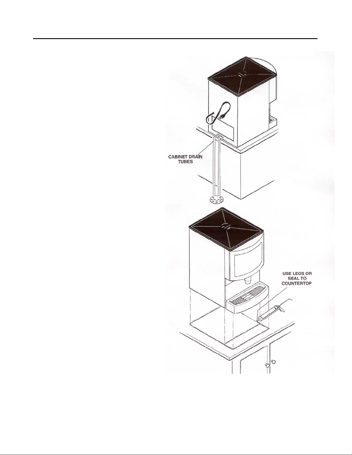
Drain Line Installation (Dispenser)
Connect a ¾” ID flexible drain hose to
the drain nipple located under the ice
storage bin. Clamp the hose in place
and insulate the hose to prevent
condensation.
Connect a ¾” ID flexible drain hose
to the drain tube at the back of the
drain pan. Clamp the drain hose
in place.
Dispenser Installation
If the dispenser is to be sealed to the
counter top, the drain tubing should be
available and planned such that the
connections may be finished after the
unit has been sealed to the counter.
Sealing may be accomplished by the
Use of RTV rubber sealant such as
Dow Corning 731.
With the unit located on the counter
as desired:
Tilt or lift the unit to expose the bottom
flanges of the base frame.
Apply the sealant to cover the bottom
Flanges of the base frame
Return the unit to the desired position
on the counter top.
Add sealant around the base frame and
Counter top to provide a seal with a radius
of ½ inch. Follow the sealant manufacturer’s
instructions on the package for working with
the sealant, and cleaning up.
Seal around all access holes in the counter
Top with Permagum or Mortite caulk
or an equivalent material.
Route the drain lines to the building drain.
The drain lines must be pitched and vented
to ensure proper flowage of the wastewater.
Page 5
Page 7
IOD16022
Installation: General IOD22030
Final Preparation
Install the drain pan on the dispenser by engaging the slots in the metal backplate of the drain pan
onto the brackets protruding from the lower left and right hand corners of the dispenser front. Push
down on the drain pan to lock it into place.
When applicable, seal the drain pan to the counter top. If the dispenser is to be sealed to the counter
top, use the sealant recommended in the “Dispenser Installation” section of the instructions.
Place the cup rest into the drain pan.
Install the fluorescent bulb into the bulb holders located on the top sloped portion of the front of the
dispenser.
Place the merchandiser on the unit.
Sanitize the ice storage system. (See page 9)
Start-Up
Fill the bin with sanitary ice.
Place the cover on top of the dispenser.
Note:
This unit is provided with a timer that will activate the ice dispenser rotor for 1 to 6
seconds each time the unit is plugged into an electrical outlet and every 2 hours thereafter.
The agitation cycle helps to keep the ice from fusing together during long periods of non-use.
No ice is dispensed during the agitation.
Plug the unit’s power cord into the electrical outlet. The rotor should turn for a few seconds and the
fluorescent bulb should illuminate. Dispense several containers of ice.
Check all connections including drain hoses for leaks. Repair as required.
Page 6
Page 8

IOD16022
Installation: General IOD22030
Ice Machine Installation
Make sure the counter the dispenser is place on is structurally able to hold the combined weight of the
dispenser, ice and ice machine.
Remove the dispenser cover. (Retain for future use)
Place the appropriate stainless steel KBT adapter onto the top of the dispenser.
22 inch wide ice machine on a 22-inch wide dispenser. Part number KBT2222
22 inch wide ice machine on a 30-inch wide dispenser. Part Number KBT2230
30 inch wide ice machine on a 30-inch wide dispenser. Part Number KBT3030
Install the thermostatic bin control kit when applicable. Part Number 1051020-02
Note: The thermostatic bin control kit is required on all ICE Series Cubers.
Using silicone sealant, place a bead of sealant onto the top edges of the area on the adapter where
the ice machine will go.
Install the ice machine onto the dispenser, center the machine left to right and align the machine flush
to the back.
Install the thermostatic bin control cap tube into the thermal well mounted in the bin.
Note: The thermostatic bin control kit is required on all ICE Series Cubers.
Fasten together at the back of the machine using fasteners from the icemaker and mounting hardware
from the kit.
Place the front cover plate onto the dispenser in front of the ice machine.
Follow the ice machine start-up instructions included with the ice machine.
Completion
Make a final check for any leaks and correct as necessary.
Reinstall the splash panel and secure it with two Phillips head screws.
Check for proper operation of the dispense system.
Instruct the site manager regarding the requirements for maintaining, operation and sanitizing the
dispenser.
Page 7
Page 9

IOD16022
Cleaning and Sanitizing IOD22030
The dispenser must be cleaned and sanitized periodically as prescribed by local health authority or
the product supplier, which ever has jurisdiction. Ice-O-Matic recommends the dispenser be cleaned
and sanitized at least monthly if not specified by local code requirement.
Dispenser Cleaning and Sanitizing Procedures
WARNING: When using cleaning fluids or any chemicals, rubber gloves and eye protection
should be worn.
The sink, grill and splash panel should be cleaned daily.
The ice storage system should be sanitized monthly.
Daily:
Lift up and remove the grill from the sink.
Use soap, hot water and a clean cloth to wash the sink and splash panel: rinse with hot water,
allowing plenty of hot water to run down the drain.
Wash the grill, then rinse with clean water. Place the grill back in sink.
Clean all exterior surfaces of the unit with warm water and a sponge. Rinse out the sponge with clean
water, wring excess water out of the sponge, and wipe off external surfaces of the unit. Wipe unit dry
with a clean soft cloth. Do not use abrasive type cleaners.
Pour hot water
down sink to clean
out drain
Splash panel
Grill
Page 8
Page 10

IOD16022
Cleaning and Sanitizing IOD22030
Monthly And Initial Start-Up:
Sanitize the ice storage system
Disconnect power to the dispenser and ice machine.
Remove the dispenser front cover plate in front of the ice machine and discard all remaining ice,
Mix a solution of 1 ounce of household bleach to 2 gallons of potable water, or: mix a solution of any
approved sanitizer, following the directions for mixing and applying that sanitizer.
Unscrew the sweep arm from the rotor shaft,
and pull the rotor from the hopper.
Using a clean cloth or sponge, wipe all interior
surfaces of the storage hopper with the sanitizing
solution, allow to air dry.
Wipe all surfaces of the rotor and sweep arm
with the sanitizing solution, allow to air dry.
Lift up & out and remove the upper front panel.
Twist the clear ice chute 1/3 turn and pull down to
remove.
Locate the two thumbscrews holding the upper ice
chute and remove them. Remove the upper ice chute
from the machine.
Thoroughly wipe the surfaces of the bin door and both ice
chutes with the sanitizing solution, and allow to air dry.
Place the upper ice chute back into the dispenser and secure with the thumb screws.
Place the clear ice chute back into the dispenser and replace the upper front panel.
Reassemble the rotor and sweep arm assembly and replace the dispenser cover plate.
Reconnect power to the ice machine and dispenser.
Page 9
Page 11

IOD16022
Service Diagnosis/Electrical Sequence IOD22030
Service Diagnosis
PROBLEM PROBABLE CAUSE CORRECTION
Will not dispense No ice in hopper Fill bin with ice
ice
Vend switch does not close Check vend switch, replace if open
Drive motor not working Check drive motor, replace if not working
Door solenoid will not open door Check/replace door and solenoid
Rotor will not turn Check hub of rotor
Relay for vend switch does not Check relays, replace as required
close during operation
Electrical Sequence Reference Wiring Diagram, Page 20-21
Ice Vending
Ice is dispensed as long as the vend lever or push button is depressed or until the bin is empty.
When the ice vend lever or push button is depressed, the vend switch closes, and makes a circuit to
the coil of relay A.
When relay A is energized, relay A’s contacts 4-6 and 5-3 close. Relays A’s contacts 5-1 open
When relay A’s contacts 4-6 close, they make a circuit to the door solenoid, which opens the ice door.
When relays A’s contacts 5-3 close, they make a circuit to the coil of relay B.
When relays A’s contacts 5-1 open, the circuit to the timer is opened.
When relay B’s coil is energized, it closes a circuit to the gearmotor, and the gearmotor turns the
rotor.
Agitation
Relay A’s contacts 5-1 are closed and make a circuit to the timer.
The timer is energized when the unit is not dispensing. The timer switch will close for a few seconds
every two hours.
When the timer switch is closed, it makes a circuit to relay B’s coil.
When relay B is energized, it powers the gearmotor and the rotor is turned.
Page 10
Page 12

IOD16022
IOD16022 and IOD2230 Service Parts IOD22030
This parts list contains the service parts available for the IOD16022 and IOS22030 ice only dispenser.
Check the model number on the data plate and refer to the correct column listing for the specific
dispenser. These two models share many common components but also have components that are
model specific.
Check carefully that the correct part is identified and ordered.
TABLE OF CONTENTS
Cabinet Pictorial Page 12
Cabinet Parts Listing Page 13
Cabinet Front Pictorial Page 14
Cabinet Front Parts Listing Page 15
Control Box Pictorial Page 16
Control Box Parts Listing Page 17
Ice Door and Solenoid Assembly Pictorial Page 18
Ice Door and Solenoid Assembly Parts Listing Page 19
Wiring Diagram Page 20-21
Page 11
Page 13

IOD16022
IOD16022 and IOD2230 Service Parts IOD22030
Cabinet
Page 12
Page 14

IOD16022
IOD16022 and IOD2230 Service Parts IOD22030
Cabinet
IOD16022 IOD22030
Item Number Part Number Part Number Description
1 30064502 30064512 Black Lid
2 30074312 30074312 Side Panel Extension
3 3012236901 3012236901 Gearmotor Assembly
4 N/A N/A Drain Hose
5 2066110000 2066110000 Leg Kit
6 30074311 30074311 Side Panel Extension
7 1117390000 1117390000 Switch, Lock and Key
8 3002304001 3002304001 Rotor
9 3A34760001 3A34760001 Hub Assembly
10 3A34810001 3A34810001 Mounting Plate, Hub
11 3A34817001 3A34817001 Gearmotor Plate
12 3002310305 3002310305 Sweep Arm
Page 13
Page 15

IOD16022
IOD16022 and IOD2230 Service Parts IOD22030
Cabinet Front
Page 14
Page 16

IOD16022
IOD16022 and IOD2230 Service Parts IOD22030
Cabinet Front
IOD16022 IOD22030
Item Number Part Number Part Number Description
1 30064206 30064226 Cover, Merch. Black-Lever
30064218 30064238 Cover, Merch. Black-Push Button
30069901 30069901 Screws For Cover
2 3015075218 3015075418 Merch. Sign
3 3002307101 3002307101 Bezel for Ice Switch Button
4 3002307200 3002307200 Button, Ice Switch
5 30072700 30072700 Push Button Switch Bracket
6 30073000 30073000 Microswitch (Push Button)
3012157001 3012157001 Microswitch (Lever)
7 3002306801 3002306801 Ice Chute
8 30072800 30072830 Ice Chute Panel
9 3000570132 30077031 Grill/Cup rest
10 30061102 30061122 Black Drain Pan Assembly
11 3A34794005 3A34795009 Panel, Lever
3034794006 3A34795010 Panel, Push Button
12 30061810 30076010 Splash Panel
13 30073200 30073200 Screw
14 3012237201 3012237201 Boot For Microswitch
15 3A34806001 3A34806001 Lever (Lever Models Only)
16 3003072706 3003072706 Thumbscrew
Page 15
Page 17

IOD16022
IOD16022 and IOD2230 Service Parts IOD22030
Control Box
Page 16
Page 18

IOD16022
IOD16022 and IOD2230 Service Parts IOD22030
Control Box
IOD16022 IOD22030
Item Number Part Number Part Number Description
1 3000480001 3000480001 Relay
2 1193210500 1193210500 Transformer
3 2021610000 2021610000 Starter Socket
4 3012238501 3012238501 Bulb Holder
5 30073510 30073530 Control Box Cover
6 3012237701 3012237702 Fluorescent Tube
7 3002306701 3002306701 Cover
8 3013088201 3013088201 Rubber Mounts
9 3A32683003 3A32683003 Solenoid
10 3013059500 3013059500 Door Gasket
11 N/A N/A Transformer
12 3012237101 3012237101 Agitation Timer
13 3000522001 3000522001 Thumb Screw
14 3000477000 3000477000 Spout Adapter Assembly
15 3012238601 3012238601 Starter
16 3012238002 3012238002 Ballast (Not Shown)
Page 17
Page 19

IOD16022
IOD16022 and IOD2230 Service Parts IOD22030
Ice Door and Solenoid Assembly
Page 18
Page 20

IOD16022
IOD16022 and IOD2230 Service Parts IOD22030
Ice Door And Solenoid Assembly
IOD16022 IOD22030
Item Number Part Number Part Number Description
1 3A34801001 3A34801001 Ice Door
2 1061400000 1061400000 Cotter Pin (6 Req.)
3 3002308902 3002308902 Solenoid Link
3000463000 3000463000 Solenoid Link Bushings
4 3002308801 3002308801 Long Axle
5 1034580000 1034580000 Washer
6 3A32685001 3A32685001 Axle, Linkage
7 2066990000 2066990000 Solenoid
8 3A32690002 3A32690002 Torsion Spring
9 3A34802001 3A34802001 Door Hinge
10 1061400000 1061400000 Cotter Pin
11 3000463000 3000463000 Plastic Hinge Bushing (6 Req.)
3000482000 3000482000 Kit, Door Assembly
Page 19
Page 21

IOD16022
IOD16022 and IOD2230 Wiring Diagrams IOD22030
Page 20
Page 22

IOD16022
IOD16022 and IOD2230 Wiring Diagrams IOD22030
Page 21
 Loading...