

Page 1
SERVICE AND INSTALLATION MANUAL
Part Number 9081270-01
Date 9/10
THE ICE SERIES CUBERS
ICE0250 through ICE2100 SERIES*
*Includes Undercounter and 22 Inch Series
Ice-O-Matic
11100 East 45th Ave
Denver, Colorado 80239
-
Page 2

ICE Series Notes
Table of Contents
Table of Contents Page A1
General Information
How To Use This Manual Page A2
Model And Serial Number Format Page A3
Electrical And Mechanical Specifications Page A5-A8
Installation Guidelines Page A9
Electrical And Plumbing Requirements Page A10-A17
Remote Condenser Installation Page A18-A19
How The Machine Works Page A20
Undercounter Model Bin Removal Page A21-A22
Warranty Information Page A23-A24
Scheduled Maintenance
Maintenance Procedure Page B1
Cleaning and Sanitizing Instructions Page B1-B2
Winterizing Procedure Page B3
Cabinet Care Page B4
Troubleshooting Trees
How to Use The Troubleshooting Trees Page C1
Troubleshooting Trees Table Of Contents Page C2
Troubleshooting Trees Page C3-C18
Water System
Water Distribution And Components Page D1-D5
Refrigeration System
Refrigeration Cycle And Components Page E1
Harvest Cycle Page E5
Remote System Page E5-E6
Pump Down System Page E7
Refrigerant Specifications Page E8-E20
Electrical System
Control Circuit Page F1
Compressor And Start Components Page F1-F2
Untimed Freeze Cycle Page F3
Timed Freeze Cycle Page F4
Harvest Cycle Page F5-F9
Pump Down System Page F9
Wiring Diagrams Page G1
Page 3

ICE Series Table Of Contents
Table of Contents
Table of Contents Page A1
General Information
How To Use This Manual Page A2
Model And Serial Number Format Page A3
Installation Guidelines Page A5
Electrical And Plumbing Requirements Page A6-A13
Remote Condenser Installation Page A14-A15
How The Machine Works Page A16
Undercounter Model Bin Removal Page A17-A18
Warranty Information Page A19-A20
Scheduled Maintenance
Maintenance Procedure Page B1
Cleaning and Sanitizing Instructions Page B1-B2
Winterizing Procedure Page B3
Cabinet Care Page B4
Troubleshooting Trees
How to Use The Troubleshooting Trees Page C1
Troubleshooting Trees Table Of Contents Page C2
Troubleshooting Trees Page C3-C18
Water System
Water Distribution And Components Page D1-D5
Refrigeration System
Refrigeration Cycle And Components Page E1
Harvest Cycle Page E5
Remote System Page E5-E6
Pump Down System Page E7
Electrical System
Control Circuit Page F1
Compressor And Start Components Page F1-F2
Untimed Freeze Cycle Page F3
Timed Freeze Cycle Page F4
Harvest Cycle Page F5-F9
Pump Down System Page F9
Electrical Sequence ICE1400-2100 Version 3 Page F10
Wiring Diagrams Page G1
Cuber Performance Data Page H1
Specifications Page I1
Page A1
Page 4

ICE Series General Information
How To Use This Manual
Ice-O-Matic provides this manual as an aid to the service technician in installation, operation,
and maintenance of the ICE Series (electro-mechanical) cube ice machines. If used properly
this manual can also assist the service technician to troubleshoot and diagnose most of the
problems that may occur with the machine.
The first two sections of this manual provide general information and maintenance information.
The remainder of the manual beginning with Section C provides troubleshooting and service
information. Section C contains flow charts called troubleshooting trees. Page C-1 provides
instructions on using the troubleshooting trees. Each troubleshooting tree is named to describe
a particular problem with the operation of the machine.
When following the troubleshooting trees, the service technician will be led through questions
and checks and end up with a probable solution. When using the troubleshooting trees, it is
important that the service technician understand the operation and adjustments of the
components being checked and the component suspected of malfunctioning. A detailed
description of the operation and adjustments of the components as well as other service
information is available in the pages that follow Section C.
Sections D, E, and F focus on a particular system in the ice machine: water distribution system,
refrigeration system, and it is important that these sections be used together with the
Troubleshooting Trees in Section C.
Most aspects of the ICE Series machines are covered in this manual, however, should you
encounter any conditions not addressed herein, please contact the Ice-O-Matic Technical
Service Department for assistance. You may also fax, e-mail or write the Ice-O-Matic Technical
Service Department:
Ice-O-Matic
11100 E. 45th Ave.
Denver, Co. 80239
Attn: Technical Service Department
E-Mail: Tech.service@iceomatic.com
Telephone Numbers Any Service communication must include:
800-423-3367 All Department • Model Number
888-349-4423 Technical Assistance Only • Serial number
303-371-3737 • A detailed explanation of the problem
Note the warning symbol where it appears in this manual.
It is an alert for important safety information on a hazard
that might cause serious injury.
Keep this manual for future reference.
The ICE Series Service Parts Manuals are available separately.
Ice-O-Matic products are not designed for outdoor installation.
Page A2
Page 5

ICE Series General Information
Model and Serial Number Format
Model Numbers
040 0 H A
ICE
Cube Size: H=Half (3/8 X 7/8 X7/8) F=Full (7/8 X 7/8 X7/8)
Voltage: 0=115V 5=240/50/1 6=208-230/60/1 7=208-230/60/3
Approximate 24 hour ice production: (x 10 @ 70°F/21°C Air and 50°F/10°C Water)
Series: Slab ice cuber, Stainless Steel Cabinet
Serial Number Date Code
The first letter in the serial number indicates the month and decade of manufacture.
The first digit in the serial number indicates the year of manufacture.
Example: A0XX-XXXXX-Z is manufactured January 2000
A1XX-XXXXX-Z is manufactured January 2001
1990-1999 MONTH 2000-2004
M JANUARY A
N FEBRUARY B
P MARCH C
Q APRIL D
R MAY E
S JUNE F
T JULY G
U AUGUST H
V SEPTEMBER I
W OCTOBER J
Y NOVEMBER K
Z DECEMBER L
Note: The letter O and letter X are not used.
Reference new serial number format on next page.
Condenser Type: A=Air W=Water R=Remote T=Top Discharge Air Cooled
Page A3
Page 6
ICE Series General Information
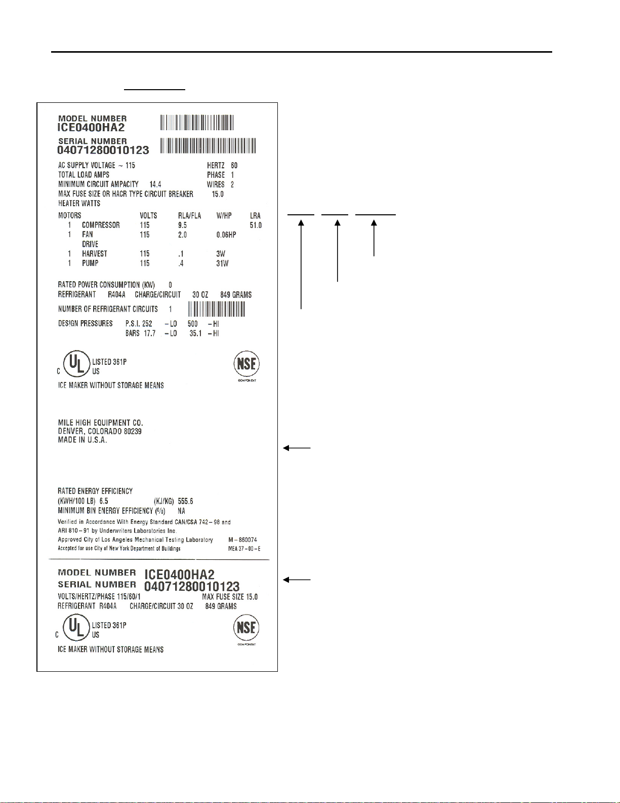
Model and Serial Number Format
Sample Only
This format is 14 characters long and begins with a
date code followed by the Ice-O-Matic identifier, and
then a sequential number. This is an entirely
numerical serial number.
The new serial number will look like the example.
0407 1280 010123
010123 is the serial identifier.
1280 is the identifier. (Ice-O-Matic)
0407 is the date code, in YYMM format. (2004 July)
The date code will change monthly and yearly to
reflect the date of manufacture.
Large data plate will be placed on the back of
the unit.
Small data plate will be placed by the service
valves.
Page A4
Page 7

ICE Series General Information
Installation Guidelines
Note: Installation should be performed by an Ice-O-Matic trained Service Technician.
For proper operation of the Ice-O-Matic ice machine, the following installation guidelines must be
followed. Failure to do so may result in loss of production capacity, premature part failures, and
may void all warranties.
Ambient Operating Temperatures
Minimum Operating Temperature: 50°F (10°C)
Maximum Operating Temperature 100°F (38°C), 110°F (43°C) on 50 Hz. Models.
Note: Ice-O-Matic products are not designed for outdoor installation.
Incoming Water Supply (See Plumbing Diagram for line sizing Page A6-A13)
Minimum incoming water temperature: 40°F (4.5°C)
Maximum incoming water temperature: 100°F (38°C)
Minimum incoming water pressure: 20 psi (1.4 bar)
Maximum incoming water pressure: 60 psi (4.1 bar)
Note: If water pressure exceeds 60 psi (4.1 bar), a water pressure regulator must be
installed.
Drains: All drain lines must be installed per local codes. Flexible tubing is not recommended.
Route bin drain, purge drain and water condenser drain individually to a floor drain. The use of
condensate pumps for draining water is not recommended by Ice-O-Matic. Ice-O-Matic assumes
no responsibility for improperly installed equipment.
Water Filtration: A water filter system should be installed with the ice machine.
Clearance Requirements: Self contained air cooled ice machines must have a minimum of 6
inches (15cm) of clearance at the rear, top, and sides of the ice machine for proper air circulation.
Stacking: If the ice machines are to be stacked, refer to the instructions in the stacking kit.
Ice-O-Matic does not endorse stacking air-cooled ice machines.
Dispenser Application: A thermostatic bin control kit must be installed if the ICE Series ice
machine is placed on a dispenser. A bin top may or may not be required. (Exception is the
CD400 Dispenser)
Electrical Specifications: Refer to the serial plate at the rear of the ice machine or the charts
starting on page H1.
Adjustments
Level the machine within 1/8 inch in all directions.
Check the bin control for proper adjustment, Page F9
Check the water in the water trough for proper level, Page D1
Check the ice bridge for proper thickness, Page F4
Check the cam switch adjustment. Page F8
Check the water regulating valve adjustment if water cooled, Page E2
Page A5
Page 8
ICE Series General Information
Electrical and Plumbing Requirements: ICEU150, ICEU200, ICEU205 and ICEU206
Page A6
Page 9
ICE Series General Information
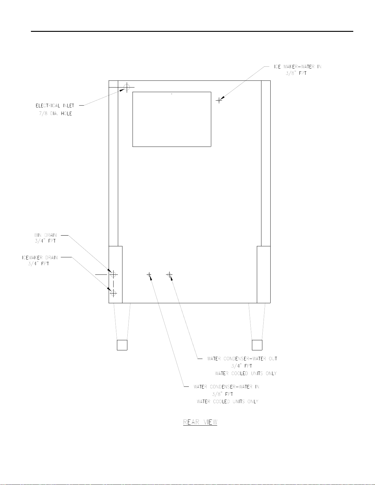
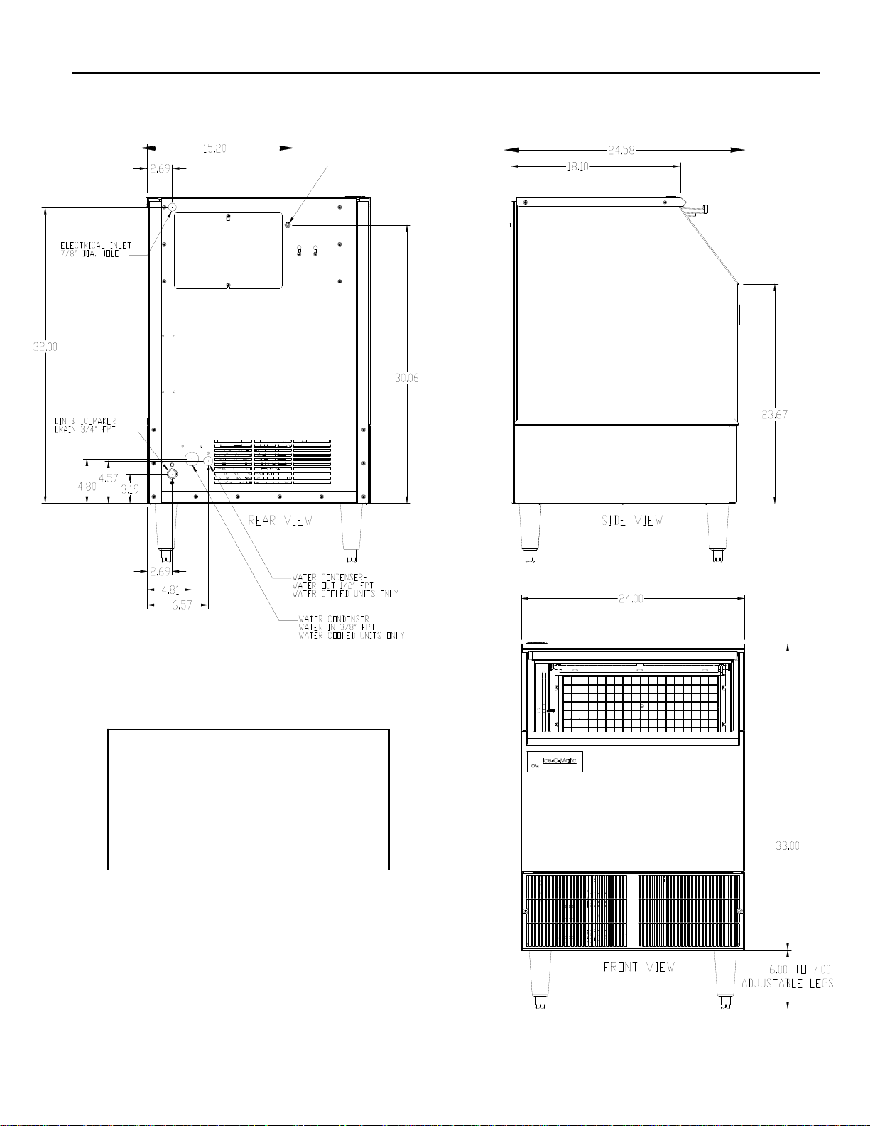
Electrical and Plumbing Requirements: ICEU150, 220, 225 and 226
ICE MAKER WATER-IN
3/8 FPT OR 1/4 Male Flare
Note: The ICEU150, ICEU220, ICEU225
and ICEU226 do not have a splash
curtain.
These models utilize a thermostatic
bin control in place of a mechanical
bin switch.
Page A7
Page 10
ICE Series General Information
Electrical and Plumbing Requirements: ICEU300 and 305
ICE MAKER WATER-IN
3/8 FPT OR 1/4 Male Flare
Note: The ICEU300 does not have a
splash curtain.
This model utilize a thermostatic bin
control in place of a mechanical bin
switch.
Page A8
Page 11
ICE Series General Information
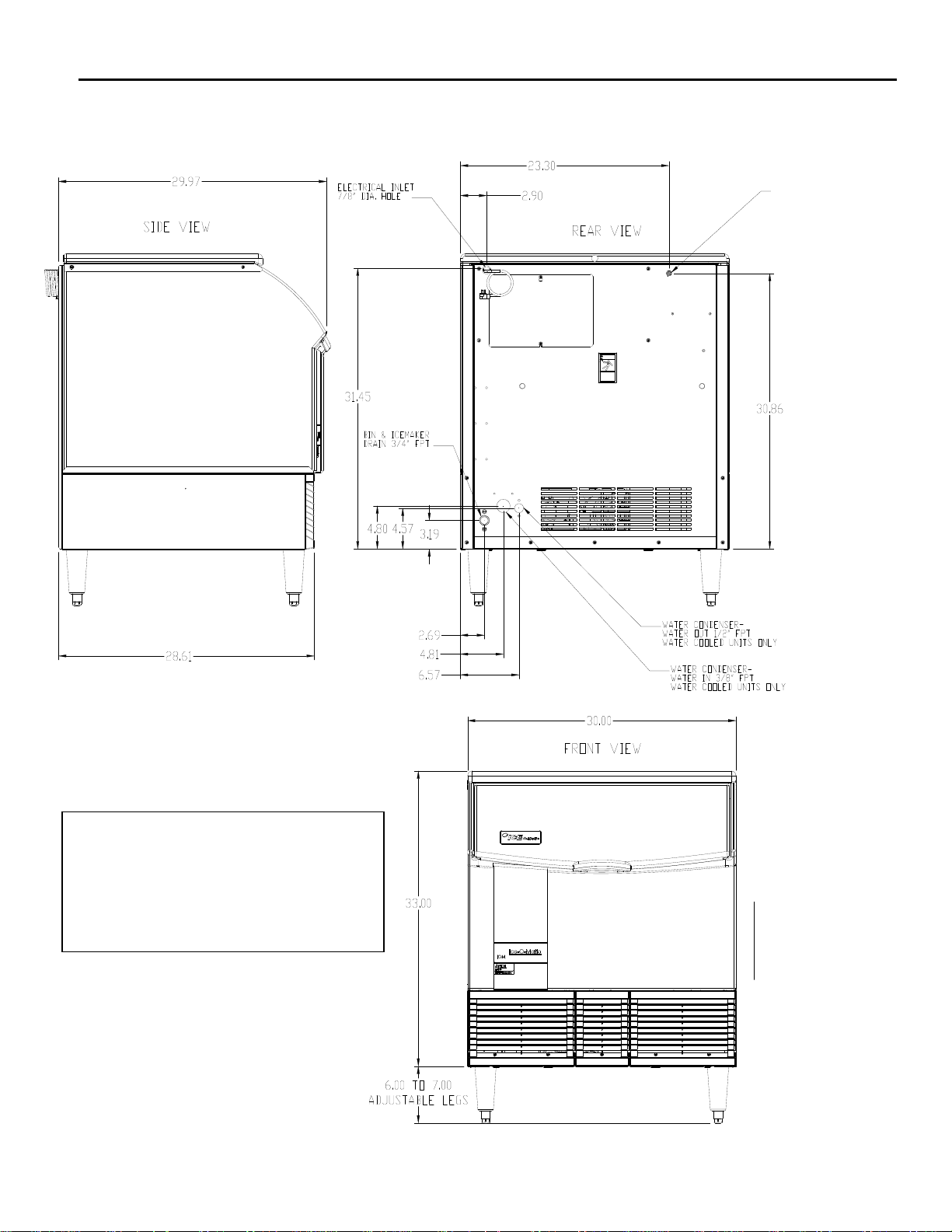
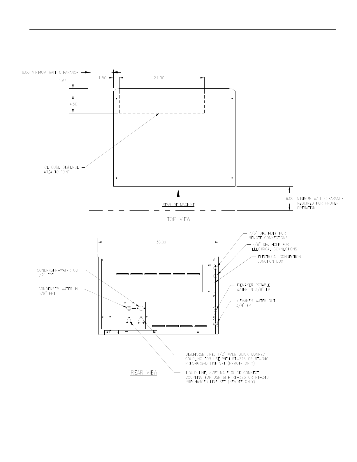
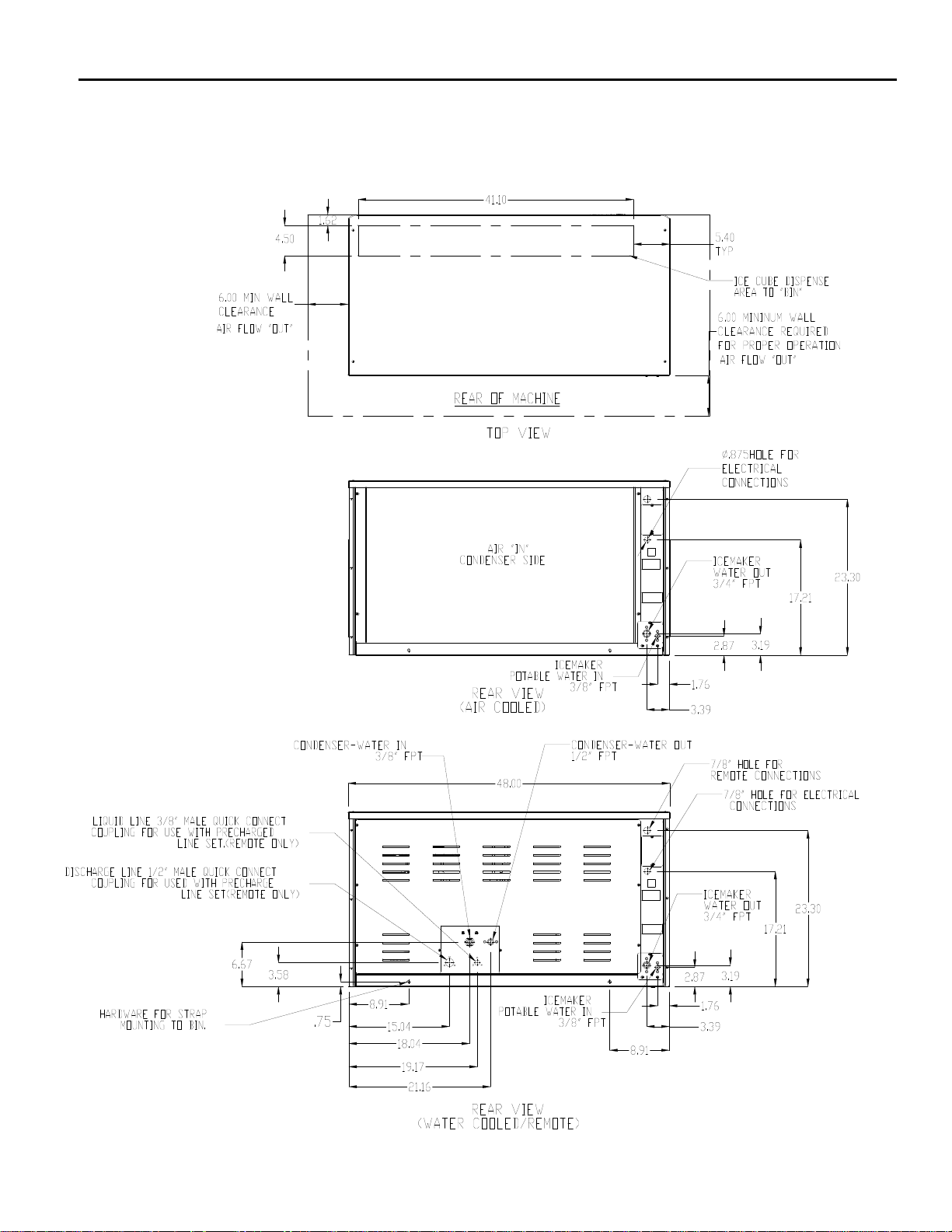
Electrical and Plumbing Requirements: ICE0250, ICE0400, ICE0500, ICE0606, ICE0806
and ICE1006 (30 Inch Wide Cubers)
Page A9
Page 12
ICE Series General Information
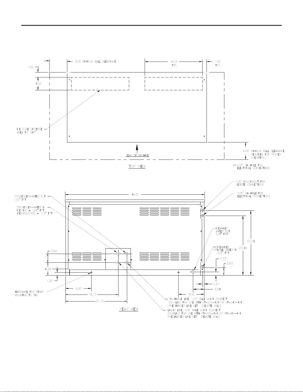
Electrical and Plumbing Requirements: ICE1406, ICE1806, ICE2106 (48 Inch Wide Cubers)
Prior to January 2008
Page A10
Page 13
ICE Series General Information
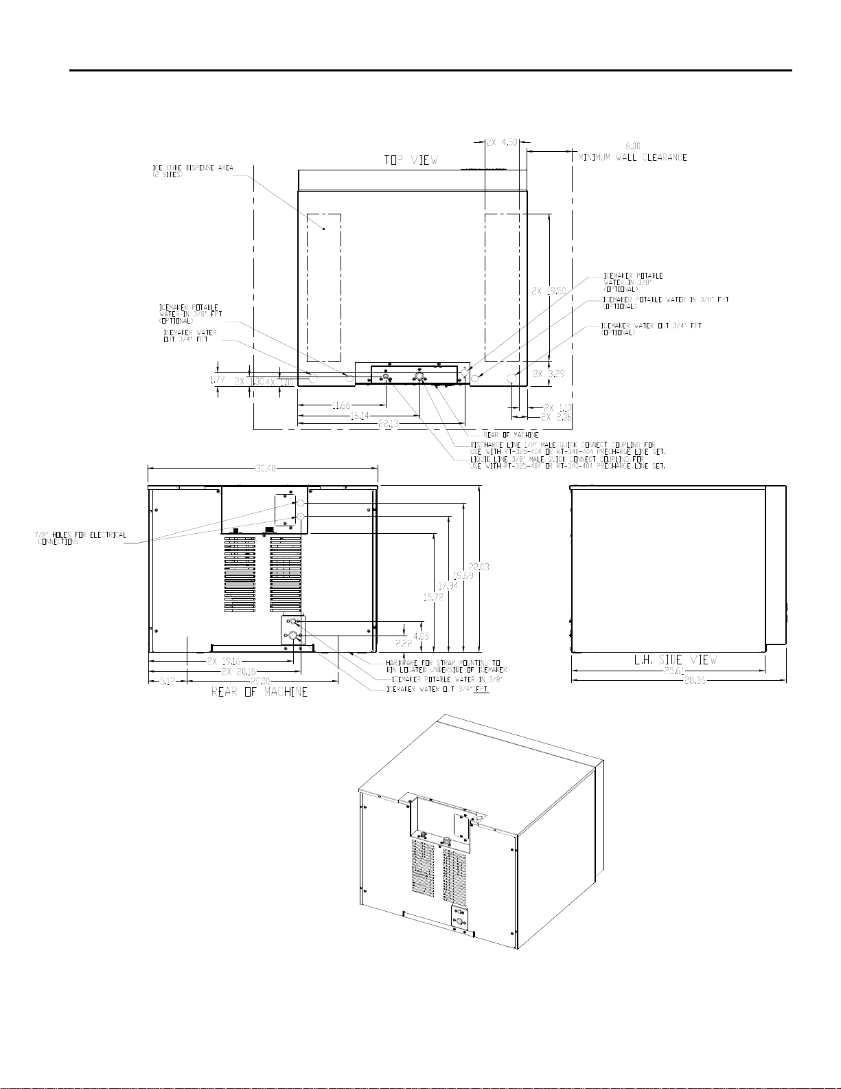
Electrical and Plumbing Requirements: ICE0320 and ICE0520 (22 Inch Wide Cubers)
Page A11
Page 14
ICE Series General Information
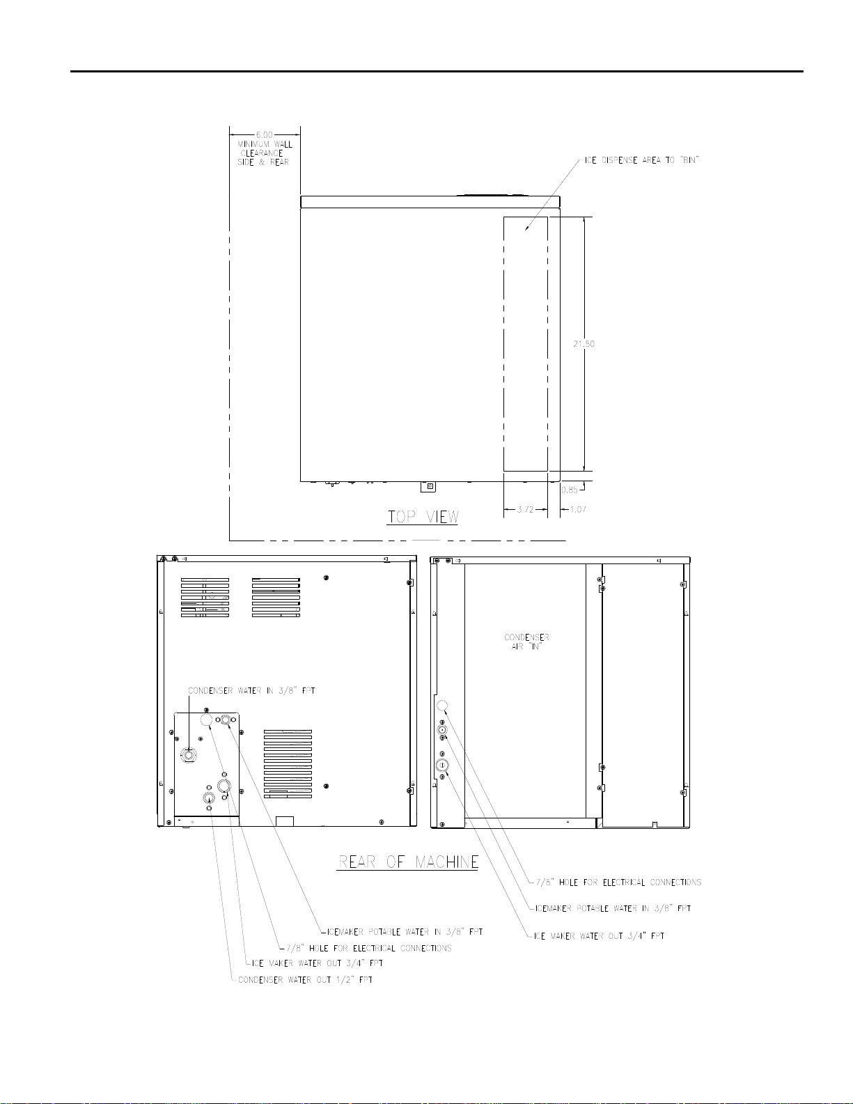
Electrical and Plumbing Requirements: ICE1400, ICE1800 and ICE2100 Revision 3
(From January 2008)
Page A12
Page 15
ICE Series General Information
Electrical and Plumbing Requirements: ICE1506 Remote
Page A13
Page 16
ICE Series General Information
Remote Condenser Installation
For proper operation of the Ice-O-Matic ice machine, the following installation guidelines must be
followed. Failure to do so may result in loss of production capacity, premature part failure, and
may void all warranties.
Installation Guidelines
Ambient operating temperatures: -20°F (-28.9°C) to 120°F (48.9°C)
Maximum refrigerant line length: 60 ft. (18.29 Meters)
Maximum vertical rise: 16 ft. (4.88 Meters)
Minimum condenser height: ICE Series ice machine remote condensers must not be
installed more than 6 feet (1.3 meters) below the refrigerant line quick connects at the rear of the
ice machine. No part of the refrigerant lines, between the ice machine and the remote
condenser, should fall below this point. Condensers must have a vertical airflow.
Air Flow
Page A14
Page 17
ICE Series General Information
The following remote ice makers incorporate the mixing valve in the condenser. This configuration allows
up to a 100 foot calculated remote line set run. Reference the diagram below to calculate the maximum 100
foot line set run.
ICE Machine Model Number Remote Condenser Model Number
ICE2100R3&4 VRC5061B
ICE1800R3&4 VRC5061B
ICE1400R3&4 VRC2661B
ICE1506HR2&3 VRC2661B
ICE1006R3&4 VRC2061B
ICE0806R3&4 VRC2061B
ICE0606R3&4&5 VRC1061B
ICE0500R3&4 &5 VRC1001B
Limitations for new remote machines that have the mixing valve mounted in the condenser.
Maximum Rise is 35 feet.
Maximum Drop is 15 feet.
Maximum equivalent run is 100 feet.
Formula for figuring maximum equivalent run is as follows:
Rise x 1.7 + Drop x 6.6 + horizontal run = equivalent run.
Examples: 35 ft. rise x 1.7 + 40 ft. horizontal = 99.5 equivalent feet line run
35 ft. rise
40 ft. horizontal
Verify the ICE machine is compatible with the remote
condenser. Some ice machines and some remote
condensers may or may not have a Mixing Valve (Head
Master). Only one valve is required per system. Kits are
available to modify the condenser for compatibility. For
more information contact your Ice-O-Matic Distributor.
34 ft. horizontal
10 ft. drop x 6.6 + 34 ft horizontal = 100
equivalent feet line run
Page A15
10 ft. drop
Page 18

ICE Series General Information
How the ICE Machine Works
A general description of how the ICE Series cubers work is given below. The remainder of the
manual provides more detail about the components and systems.
With the ICE/OFF/WASH switch in the ICE position, the compressor, water pump and condenser
fan motor (when applicable) will energize starting the freeze cycle.
During the freeze cycle, water is circulated over the evaporator(s) where the ice cubes are formed.
When the suction pressure has pulled down to the proper cut-in pressure of the timer initiate
(pressure control), the contacts will close and energize the time delay module (timer). See Page
F3 for proper cut-in pressures. At this time the cubes will close to completion.
The remaining portion of the freeze cycle is determined by the timer setting. The timer is pre-set at
the factory to achieve the proper ice bridge thickness but may need to be adjusted upon initial
start-up, see Page F4 for initial timer settings.
Once the amount of time on the timer has passed, the control relay will be energized and the
machine will enter harvest. Power is now supplied to the water purge valve, hot gas valve, and the
harvest motor. The water purge valve opens, and allows the water pump to purge the water
remaining in the water, removing impurities and sediment. This allows the machine to produce
clear ice cubes and keep mineral build up at a minimum. The hot gas solenoid opens allowing hot
gas to go directly to the evaporator, heating the evaporator and breaking the bond between the
evaporator and the ice slab.
The harvest assist motor, which is also energized during harvest, turns a slip clutch, which pushes
a probe against the back of the ice slab. Once the evaporator has reached approximately 40°F
(4.5°F) in temperature, the slip clutch overcomes the bonding of the ice to the evaporator and
pushes the slab of ice off of the evaporator and into the storage bin. The clutch also actuates a
switch that rides on the outer edge of the clutch. When the clutch completes one revolution, the
switch is tripped and the machine enters the next freeze cycle.
When ice drops into a full bin during harvest, the splash curtain is held open which activates a bin
switch shutting the machine off. When ice is removed from the bin, the splash curtain will close
and the machine will come back on.
Page A16
Page 19
ICE Series General Information
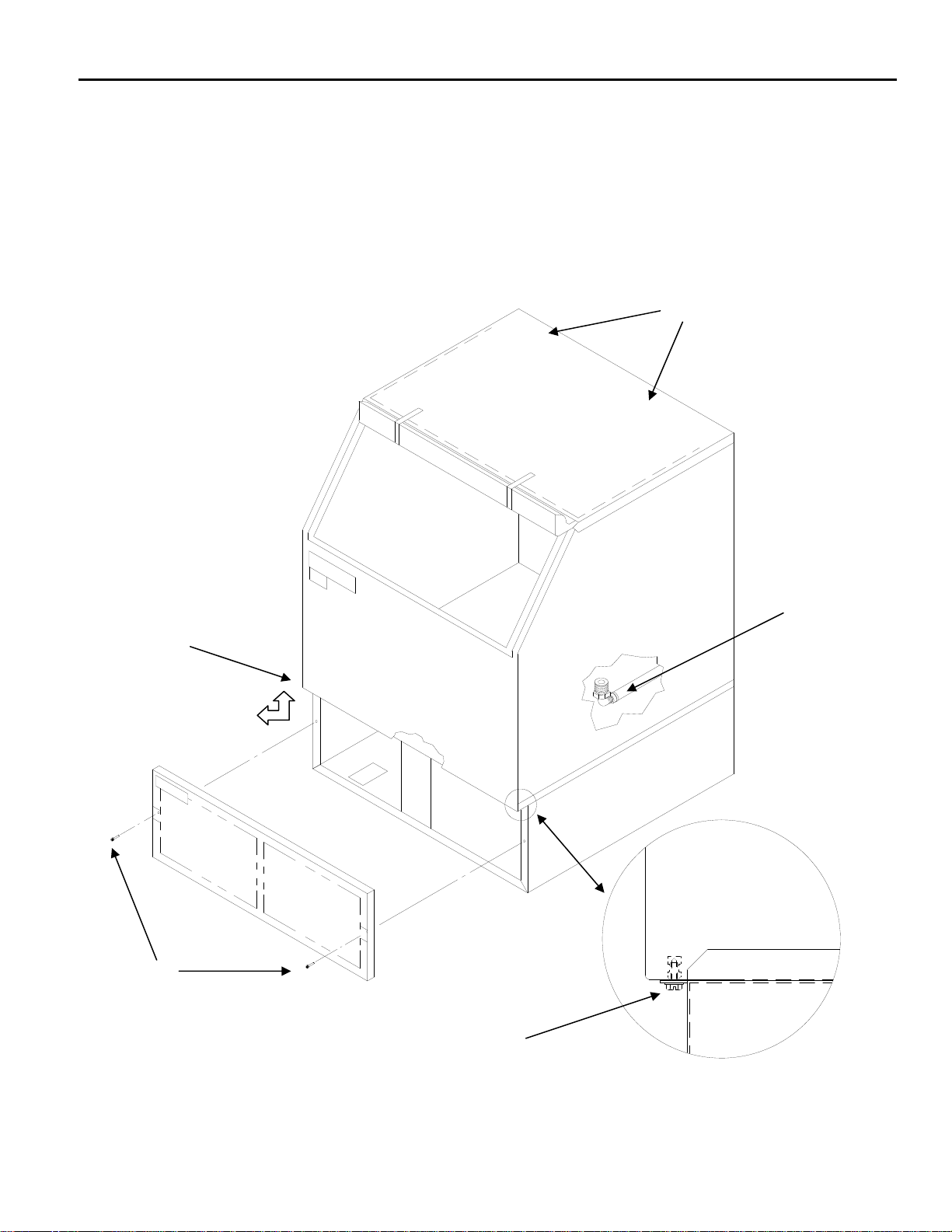
Undercounter Bin Removal-ICEU300 and ICEU150-220 (From 6/08) Series
The storage bin can be removed by:
1 Remove the lower grill.
2. Remove two screws securing bin to cabinet base.
3. Remove the thumbscrews from the back wall of the bin.
4. Disconnect bin drain.
5. Lift front of bin slightly and pull bin forward to remove.
3
2
Page A17
Page 20
ICE Series General Information
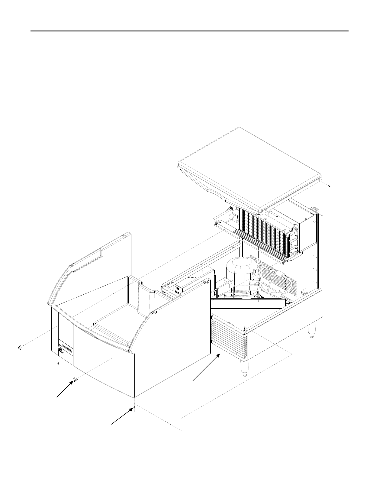
Undercounter Bin Removal-ICEU150/200 Series (Prior to 6/08)
The storage bin can be removed by:
1. Remove the two screws at the rear of the top panel.
2. Remove the two screws from the front panel.
3. Remove two screws securing bin to cabinet base.
4. Disconnect bin drain.
5. Lift front of bin slightly and pull bin forward to remove.
1
2
4
5
3
Page A18
Page 21

ICE Series General Information
Warranty Information
Every Ice-O-Matic machine is backed by a warranty that provides both parts and labor coverage.
PARTS LABOR
Two years on all parts* Two years on all components*
Three years on all ICE Maker parts* Three years on all cube ICE Maker components*
Five years on compressors*
Five years on cuber evaporators*
Water Filtration System Extended Warranty Program
Purchase a new Ice-O-Matic IFQ or IFI Series Water Filtration System with a new ICE Series ICE
Machine, replace the filter cartridge every 6 month and Ice-O-Matic will extend the limited cuber
evaporator warranty to 7 years parts and labor.
•New machine and filter must be installed at same time.
•Must send in both the machine and water filter registration cards within 10 days of
installation.
•Must send in additional registration card for each new filter installed. This must be done
every 180 days (6 months) or less.
•Program is available with all IFQ and IFI filter systems.
•Replacement filter must be model number IOMQ or IOMWFRC.
•Available in the USA and Canada only.
Warranty If, during the warranty period, customer uses a part for this Ice-O-Matic equipment other
than an unmodified new part purchased directly from Ice-O-Matic, Ice-O-Matic Distributors, or any
of its authorized service agents and/or the part being used is modified from its original
configuration, this warranty will be void. Further, Ice-O-Matic and its affiliates will not be liable for
any claims, damages or expenses incurred by customer which arises directly or indirectly, in whole
or in part, due to the installation of any modified part and/or part received from an unauthorized
service center. Adjustments are not covered under warranty.
Warranty Procedure
Matic authorized representative travels to the installation address to perform warranty service, the
service representative will advise customer the warranty is void. Such service call will be billed to
the customer at the authorized service center’s then-applicable time and material rates.
If the customer is using a part that results in a voided warranty and an Ice-O-
Page A19
Page 22

ICE Series General Information
•
•
•
Ice-O-Matic
Domestic & International Limited Warranty
Mile High Equipment LLC (the “Company”) warrants Ice-O-Matic brand ice machines, ice dispensers, remote condensers, water filters, and ice
storage bins to the end customer against defects in material and factory workmanship for the following:
• Cube ice machines,”GEM” model compressed ice
machines ,” MFI” model flake ice machines and remote
condensers. - Thirty-six (36) months parts and labor
• “EF” and “EMF” model flake ice machines - Twenty-four
(24) months parts and labor
• CD model dispensers - Thirty-six (36) months parts and
labor
An additional twenty-four (24) month warranty on parts (excluding labor) will be extended to all cube ice machine evaporator plates and
compressors, “GEM” model compressed ice machine compressors, and “MFI” model flake ice machine compressors from the date of original
installation. An additional thirty-six (36) month warranty on parts (excluding labor) will be extended to all “EF” and “EMF” model flake ice machine
compressors from the date of original installation. The company will replace EXW (Incoterms 2000) the Company plant or, EXW (Incoterms 2000)
the Company-authorized distributor, without cost to the Customer, that part of any such machine that becomes defective. In the event that the
Warranty Registration Card indicating the installation date has not been returned to Ice-O-Matic, the warranty period will begin on the date of
shipment from the Company. Irrespective of the actual installation date, the product will be warranted for a maximum of seventy-two (72) months
from date of shipment from the Company.
ICE-model cube ice machines which are registered in the Water Filter Extended Warranty Program will receive a total of eighty-four (84) months
parts and labor coverage on the evaporator plate from the date of original installation. Water filters must be installed at the time of installation and
registered with the Company at that time. Water filter cartridges must be changed every six (6) months and that change reported to the Company to
maintain the extended evaporator warranty.
No replacement will be made for any part or assembly which (I) has been subject to an alteration or accident; (II) was used in any way which, in the
Company’s opinion, adversely affects the machine’s performance; (III) is from a machine on which the serial number has been altered or removed;
or, (IV) uses any replacement part not authorized by the Company. This warranty does not apply to destruction or d amage caused by unauthori zed
service, using other than Ice-O-Matic authorized replacements, risks of transportation, damage resulting from adverse environmental or water
conditions, accidents, misuse, abuse, improper drainage, interruption in the electrical or water supply, charges related to the replacement of nondefective parts or components, damage by fire, flood, or acts of God.
This warranty is valid only when installation, service, and preventive maintenance are performed by a Company-authorized distributor, a Companyauthorized service agency, or a Company Regional Manager. The Company reserves the right to refuse claims made for ice machines or bins used
in more than one location. This Limited Warranty does not cover ice bills, normal maintenance, after-install adjustments, and cleaning.
Limitation of Warranty
This warranty is valid only for products produced and sh ipped from the Company after January, 2007. A product produced or installed
before that date shall be covered by the Limited Warranty in effect at the date of its shipment . The liability of the Company for breach of
this warranty shall, in any case, be limited to the cost of a new part to replace any part, which proves to be defective. The Company
makes no representations or warranties of any character as to accessories or auxiliary equipment n ot manufactured by the Company.
REPAIR OR REPLACEMENT AS PROVIDED UNDER THIS WARRANTY IS THE EXCLUSIVE REMEDY OF THE CUSTOMER. MILE HIGH
EQUIPMENT SHALL NOT BE LIABLE FOR ANY INCIDENTAL OR CONSEQUENTIAL DAMAGES FOR BREACH OF ANY EXPRESS OR
IMPLIED WARRANTY ON THIS PRODUCT. EXCEPT TO THE EXTENT PROHIBITED BY APPLICABLE LAW, ANY IMPLIED WARRANTY OR
MERCHANTABILITY OR FITNESS FOR A PARTICULAR PURPOSE ON THIS PRODUCT IS LIMITED IN DURATI ON TO THE LENGTH OF THIS
WARRANTY.
Filing a Claim
All claims for reimbursement must be received at the factory within 90 days from date of ser vice
this time period will be void. The model, the serial number and, if necessary, proof of installation, must be included in the claim. Claims for labor
to replace defective parts must be included with the part claim to receive consideration. Payment on claims for labor will be limited to the published
labor time allowance hours in effect at the time of repair. The Company may elec t to require the return of components to validate a claim. Any
defective part returned must be shipped to the Company or the Company-authorized distributor, transportation charges pre-paid, and properly
sealed and tagged. The Company does not assume any responsibility for any expenses incurred in the field incidental to the repair of equipment
covered by this warranty. The decision of the Company with respect to repair or replacement of a part shall be final. No person is authorized to give
any other warranties or to assume any other liability on the Company’s behalf unless done in writing by an officer of the Company.
GOVERNING LAW
This Limited Warranty shall be governed by the laws of the state of Delaware, U.S.A., excluding their conflicts of law principles. The United Nations
Convention on Contracts for the International Sale of Goods is hereby excluded in its entirety from application to this Limited Warranty.
Mile High Equipment LLC, 11100 East 45
Parts and Labor
Ice storage bins -Twenty-four (24) month parts and labor
IOD model dispensers - Twenty-four (24) months parts, Twelve (12) months
labor
Water filter systems - Twelve (12) months parts and labor (not including filter
cartridges)
to be eligible for credit. All claims outside
th
Avenue, Denver, Colorado 80239 (303) 371-3737
January 2007
Page A20
Page 23

ICE Series Scheduled Maintenance
Maintenance
Note: Maintenance should be performed by an Ice-O-Matic trained Service Technician.
Electrical shock and/or injury from moving parts inside this
machine can cause serious injury. Disconnect electrical
supply to machine prior to performing any adjustments or
repairs.
Failure to perform the required maintenance at the frequency specified will void warranty coverage
in the event of a related failure. To insure economical, trouble free operation of the machine, the
following maintenance is required every 6 months.
Maintenance Procedure
1. Clean the ice-making section per the instructions below. Cleaning should be performed a
minimum of every 6 months. Local water conditions may require that cleaning be performed more
often.
2. Check ice bridge thickness. See page F4 for proper thickness and adjustment procedure.
3. Check water level in trough. See page D1 for proper water level and adjustment.
4. Clean the condenser (air-cooled machines) to insure unobstructed air flow.
5. Check for leaks of any kind: Water, Refrigerant, Oil, Etc.
6. Check the bin switch for proper adjustment. See page F9 for bin switch adjustment.
7. Check the cam switch adjustment. See page F8 for cam switch adjustment.
8. Check the water valve (water-cooled machines) for proper adjustment. See page E2.
9. Check all electrical connection.
10. Oil the fan motor if the motor has an oil fitting. (Self contained air-cooled models only)
Cleaning and Sanitizing
1. Harvest problems may occur if the following procedures are not performed every 6 months.
2. Remove the ice machine front panel.
3. Make sure that all the ice is off of the evaporator. If ice is being made, wait for cycle
completion, then turn the machine “OFF” at the ICE/OFF/WASH selector switch.
4. Remove or melt all ice in the storage bin.
Page B1
Page 24

ICE Series Scheduled Maintenance
Cleaning and Sanitizing (continued)
5. Add recommended amount of approved Nickel Safe ice machine cleaner to the water trough
according to label instructions on the container.
6. Initiate the wash cycle at the ICE/OFF/WASH switch by placing the switch in the “WASH”
position. Allow the cleaner to circulate for approximately 15 minutes to remove mineral
deposits.
7. Depress the purge switch and hold until the ice machine cleaner has been flushed down the
drain and diluted by fresh incoming water.
8. Terminate the wash cycle at the ICE/OFF/WASH switch by placing the switch in the “OFF”
position. Remove the splash curtain and inspect the evaporator and water spillway to assure all
mineral residue has been removed.
9. If necessary, wipe the evaporator, spillway and other water transport surfaces with a clean soft
cloth to remove any remaining residue. If necessary, remove the water distribution tube,
disassemble and clean with a bottlebrush, see page D2. Reassemble all components and
repeat steps 4 through 7 as required to remove residue.
10. Turn OFF ice machine water supply and clean the water trough thoroughly to remove all scale
or slime build-up. If necessary, remove the water trough to reach all splash areas and float.
11. Prepare 1½ to 2 gallons (5.7 to 7.5 liters) of approved (EPA/FDA) sodium hypochloride food
equipment sanitizer to form a solution with 100 to 200 ppm free chlorine yield.
12. Add enough sanitizing solution to fill the water trough to overflowing and place the
ICE/OFF/WASH switch to the “WASH” position and allow circulation to occur for 10 minutes
and inspect all disassembled fittings for leaks. During this time, wipe down all other ice
machine splash areas, plus the interior surfaces of the bin, deflector and door with the
remaining sanitizing solution. Inspect to insure that all functional parts, fasteners, thermostat
bulbs (if used), etc. are in place.
13. Depress the purge switch and hold until sanitizer has been flushed down the drain. Turn ON
the ice machine water supply and continue to purge to the diluted sanitizing solution for another
1 to 2 minutes.
14. Place the ICE/OFF/WASH switch to the “ICE” position and replace the front panel.
15. Discard the first two ice harvests.
Page B2
Page 25
ICE Series Winterizing Procedures
Winterizing Procedures
Important!
Whenever the ice machine is taken out of operation during the winter months, the procedure below
must be performed. Failure to do so may cause serious damage and will void all warranties.
1. Turn off water to machine.
2. Make sure all ice is off of the evaporator(s). If ice is being made, initiate harvest or wait for
cycle completion.
3. Place the ICE/OFF/WASH switch to the “OFF” position.
4. Disconnect the tubing between the water pump discharge and water distribution tube.
5. Drain the water system completely.
6. On water cooled machines, hold the water regulating valve
open by prying upward on the water valve spring with a
screwdriver while using compressed air to blow all the water out
of the condenser.
7. Remove all of the ice in the storage bin and discard.
Page B3
Page 26

ICE Series Cabinet Care
Cleaning stainless steel
Commercial grades of stainless steel are susceptible to rusting. It is important that you properly
care for the stainless steel surfaces of your ice machine and bin to avoid the possibility of rust or
corrosion. Use the following recommended guidelines for keeping your stainless steel looking like
new:
1. Clean the stainless steel thoroughly once a week. Clean frequently to avoid build-up of
hard, stubborn stains. Also, hard water stains left to sit can weaken the steel's corrosion
resistance and lead to rust. Use a nonabrasive cloth or sponge, working with, not across, the
grain.
2. Don't use abrasive tools to clean the steel surface. Do not use steel wool, abrasive sponge
pads, wire brushes or scrapers to clean the steel. Such tools can break through the "passivation"
layer - the thin layer on the surface of stainless steel that protects it from corrosion.
3. Don't use cleaners that use chlorine or chlorides. Don't use chlorine bleach or products like
Comet to clean the steel. Chlorides break down the passivation layer and can cause rusting.
4. Rinse with clean water. If chlorinated cleansers are used, you must thoroughly rinse the
surface with clean water and wipe dry immediately.
5. Use the right cleaning agent. The table below lists the recommended cleaning agents for
common stainless steel cleaning problems:
Cleaning Activity Cleaning Agent Method of Application
Routine cleaning Soap, Ammonia, Windex, or Apply with a clean cloth
detergent with water. or sponge. Rinse with
Fantastik, 409 Spic’nSpan clean water and wipe dry.
Liquid are also approve for
Stainless Steel.
Removing grease or Easy-Off or similar oven Apply generously, allow
fatty acids cleaners. to stand for 15-20 minutes.
Rinse with clean water.
Repeat as required.
Removing hard water spots Vinegar Swab or wipe with clean cloth.
and scale. Rinse with clean water and
dry.
Page B4
Page 27

ICE Series Troubleshooting Trees
How To Use The Troubleshooting Trees
The troubleshooting trees were developed to be used in conjunction with the service information in
the sections that follow. If used together as intended, these two parts of the manual will allow the
ice machine service technician to quickly diagnose many of the problems encountered with the ice
machines. When used as designed, the troubleshooting trees can lead you from a general
symptom to the most likely component to suspect as the cause of the problem. The trees are not
designed to be “parts changer guides”: please do not use them as such.
Components returned to the factory for warranty are tested by the factory and will not be covered
under the warranty policy if they are not defective.
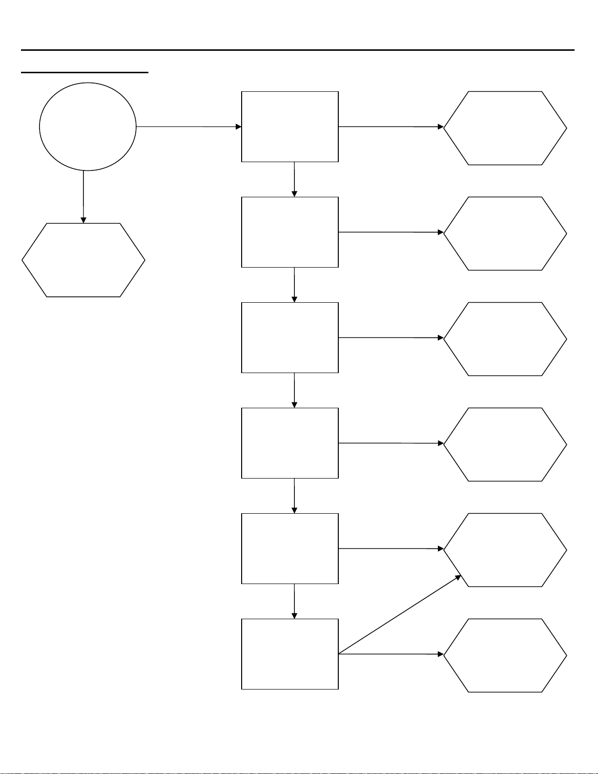
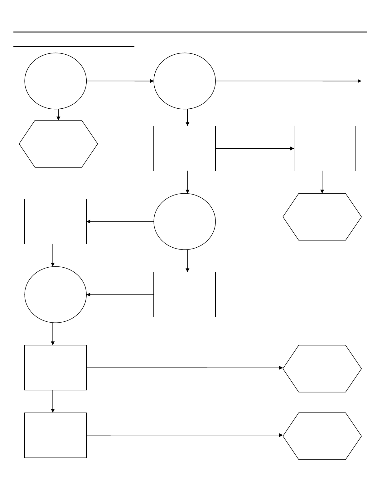
The troubleshooting trees are made of three types of boxes:
QUESTION boxes (Circle) ask a yes/no question and the answer will lead to either another
question box, a check box or a solution box.
CHECK boxes (Rectangle) will suggest a point to check for proper operation, and will often refer
you to a page in the service information sections of this manual. The result of the check may lead
to another box, or a solution box.
SOLUTION boxes (Hexagon) suggest the most likely component to cause the malfunction
described in the heading of the tree. When reaching a solution box, DO NOT immediately assume
the component is defective. The final step is to verify that the component is indeed defective, by
using the service information in the sections that follow.
To use the troubleshooting trees, first find the page with the heading describing the type of
problem occurring. Begin at the top of the page and follow the tree, step-by-step. When a check
box is reached, it may be necessary to refer to another section in the manual.
Once a solution box is reached, refer to the appropriate section to verify that the component in the
solution box is, indeed, the problem. Adjust, repair or replace the component as necessary.
?
9
!
Page C1
Page 28

ICE Series Troubleshooting Trees
Troubleshooting Trees Table Of Contents
Machine Does Not Run C3
Machine Runs, Does Not Make Ice C4 – C5
Slow Production (Cube Formation Good) C6
Low Suction Pressure C7
High Suction Pressure C8
Cubes Are Hollow C9
Uneven Bridge Thickness C10
Ice Bridge Thickness Varies Cycle To Cycle C11
Machine Produces Cloudy Ice C12
Poor Water Distribution Over Evaporator C13
Machine Does Not Enter Harvest C14
Machine Enters Harvest, Then Returns To Freeze Prematurely C15
Length Of Harvest Excessive C16
Ice Does Not Release From Evaporator C17
Hot Evaporator, Low Suction Pressure (Remote Only) C18
Page C2
Page 29
ICE Series Troubleshooting Trees
K
K
Machine Does Not Run
Is the selector
switch set to
ICE?
NO
Set selector
Switch to the
ICE position
YES NOT OK
Check for correct
power supply to the
Pressure Safety
Temperature Safety
machine
Check High
Control
Check High
Control
OK
TRIPPED
OK
OPEN
Correct field
wiring deficiency
Reset and
identify reason
for high head
pressure
Replace or
identify reason
for being open.
OK
Check Bin Control
for proper
adjustment, see
page F9
GOOD
Is this a Remote
unit?
OK
Is the Liquid line
Solenoid energized
and open?
BAD
NO
O
NOT O
Adjust as
required or
replace if
defective
Selector Switch
could be
defective, see
page F1
Find reason for
non-activity or
replace if
defective
Page C3
Page 30
ICE Series Troubleshooting Trees
Machine Runs, Does Not Make Ice
Is water
running over
the
evaporator?
NO
Go to the
Troubleshooting
Tree on page
C12
Check High
Pressure reset if
necessary
YES GO TO PAGE C5
Check for power to
the compressor
YES
Is the
compressor
running?
NO
GOOD
bad contactor or coil.
contactor coil
OK
Does the unit
have a remote
condenser?
Check contactor for
Replace if defective
Compressor or
Start
Components
could be
defective, see
page F2
OK
Continue if the
machine has a
remote
condenser
OK
Check the suction
pressure, is it low or
high?
LOW
Check refrigerant
charge
HIGH
OK
OK
NO
Check Selector
Switch,
Replace if defective
Pumpdown
Control possibly
bad
Liquid Line
Solenoid not
opening
Page C4
Page 31

ICE Series Troubleshooting Trees
Machine Runs, Does Not Make Ice (continued)
Is water
leaking out of
the Purge
Drain or Water
Trough?
YES
Repair water
leakage defect
NO
Check refrigerant
pressures, see page
E1
LOW SUCTION OK
Recover and weigh
in refrigerant charge
OK
Low side
restriction or
defective TXV
HIGH OR NORMAL
SUCTION
If head pressure is
also high, make sure
Condenser is clean
and machine has
good air flow
Check Hot Gas
Valve for leakage
during freeze, see
page E5
OK
Check for inefficient
Compressor
Page C5
Page 32

ICE Series Troubleshooting Trees
K
Slow Production (Cube Formation Good)
Does
installation
meet
guidelines?
Correct any
installation
defects
NO
YES
Check for excessive
head pressure
TOO HIGH
Is this unit air
cooled or
water cooled?
AIR
Condenser
OK
Is the Air
clean?
Check refrigeration
system, Section E
YES
Check refrigeration
system, Section E
NO
WATER
Check Water
Regulating Valve,
See page E2
O
See Condenser
service information
page E2
NOT OK
Clean
Condenser and
Condenser Fan
Blade
Adjust or
replace Water
Regulating
Valve
Page C6
Page 33

ICE Series Troubleshooting Trees
Low Suction Pressure
Does
installation
meet
guidelines?
YES
Is the water
flow over the
Evaporator
correct?
YES
Check for correct
head pressure, see
page E10
NOT OK
NO
NO
Is the
machine a
remote unit?
YES
NO
Correct
deficiency in
installation
Go to
Troubleshooting
Tree on page
C12
Low charge,
locate and
repair leak,
evacuate and
recharge
system
OK
Check TXV for
moisture based
restriction
WET SYSTEM
Replace drier,
evacuate and
recharge
system
See
Troubleshooting
Tree page C18
DRY SYSTEM NOT OK
Check for refrigerant
tubing restriction,
Check Evaporator
coil separation, see
crimps, etc.
OK
NOT OK
page E4
OK
TXV possibly
defective, see
page E3 and
page E4
Correct
restricted tubing
Replace
defective
Evaporator
Page C7
Page 34

ICE Series Troubleshooting Trees
K
High Suction Pressure
Have you
checked the
“Slow
Production”
Tree?
Is the head
pressure also
high?
Is the machine
installed to
specifications?
YES
YES
NO
NO
NO
Correct
installation
defects
Go to “Slow
Production”
Troubleshooting
Tree
Check Hot Gas
Valve, see page E5
NOT OK
Hot Gas Valve
is possibility
defective
OK
Replace
Compressor
NOT O
Check Compressor,
see page E1
OK
TXV could be
defective, see
Expansion
Valve, see page
E3 and E4
YES
Is the
Condenser
dirty?
Check for leaking
Purge valve
NO
YES
Repair or
replace
defective part
Clean the
Condenser
OK OK
Check Condenser
Fan Motor and
Blade for proper
operation, and/or
Water Valve or
Mixing Valve
NOT OK
TVX Thermal
bulb loose or
TXV could be
defective
STILL TOO
HIGH
Evacuate and
recharge system
Page C8
Page 35

ICE Series Troubleshooting Trees
K
Cubes Are Hollow
Is the water
temperature
above 100°F
(38°C)?
YES
Water
temperature too
high, correct
water
temperature
NO
Is there good
water flo w
over the
Evaporator?
NO
Go to the “Poor
Water Distribution
Over Evaporator”
Troubleshooting
Tree, page C13
YES
Is water
leaking from
the Purge
Drain?
NO
Check Timer for
proper setting, see
page F4
NOT O
Timer Initiate
Control out of
adjustment of
defective
YES
OK
Purge Valve has
an obstruction
or could be
defective
Timer Module
requires
adjustment or
could be
defective
Page C9
Page 36

ICE Series Troubleshooting Trees
Uneven Bridge Thickness
Make sure
supply water
temperature is
below 100°F
(38°C)
Check for water
leaking out of Purge
Drain
Dirty or
defective Purge
Valve
OK
NO
NO
Is water
running into
the bin?
Are the
Evaporator(s)
flooded? See
page E4 and
E5
NO
Check the suction
pressure, is it high or
low? See pageE1
YES
YES
HIGH
Problem in
water syst em,
see pages D1
and D2.
Serpentine coil
on back of
evaporator
could be
separated, see
page E4
Hot Gas Valve
could be
leaking, see
page E5
LOW
Make sure the
system is charged
properly, recover the
charge and weigh in
the correct amount
OK
Refer to page
E3 and E4 for
TXV diagnosis.
Page C10
Page 37

ICE Series Troubleshooting Trees
Ice bridge Thickness Varies Cycle To Cycle
Is air and
water temps
consistent and
within
guidelines?
YES
Check the Purge
Valve for water leaks
OK
Check Hot Gas
valve for proper
operation
NO
NOT OK
NOT OK
Correct
installation
deficiency
Clean Purge
Valve or replace
if defective
Replace Hot
Gas Valve
OK
Check Timer Initiate
Control for proper
operation
OK
Check Solid State
Timer for proper
operation
OK
TXV(s) could be
defective, see
page E3 and E4
NOT OK
NOT OK
Replace Timer
Initiate
Adjust Timer or
replace if
defective
Page C11
Page 38

ICE Series Troubleshooting Trees
Machine Produces Cloudy Ice
Is water
running evenly
across the
evaporator?
YES
Doe machine
meet
installation
guidelines?
See Section A
YES
Cloudiness is a
result of properties
in the incoming
supply water
NO
NO
See “Poor
Water Running
Over Evaporator
Troubleshooting
Tree page C13
Correct
installation
deficiency
Page C12
Page 39

ICE Series Troubleshooting Trees
Poor Water Distribution Over The Evaporator
Is the machine
level?
NO
Level the
machine
YES
OBSTRUCTED CLEAR
Is the water
level in the
Water Trough
correct? See
Section D
YES
Check Water
Distribution Tube for
obstructions or
improper assembly
See Section D
NO
Is the supply
water
pressure
correct?
Is water
leaking from
the Purge
Drain?
YES
NO
NO
YES
Correct
deficiency in
supply water
pressure
Purge valve
stuck open,
clean or replace
if defective
Float Valve not
adjusted
properly or
could be
defective
Clean Water
Distribution
Tube; insure
that it is
assembled
correctly
Check Water Pump
for proper operation
BAD
Water Pump
obstructed or
may be
defective
GOOD
Clean
Evaporator and
Spillway. See
Section B for
cleaning
instructions
Page C13
Page 40

ICE Series Troubleshooting Trees
K
KOK
K
Machine Does Not Enter Harvest
Will suction
pressure drop
below cut-in of
Timer Initiate?
YES
Does the
manual Purge
Switch
energize the
Purge Valve?
NO
Is the freeze
pattern on the
Evaporator
even?
Check for signs of a
weak Compressor,
see page E1
YES
NO
YES
Check Timer Initiate
Control for correct
cut-in pressure
Check Purge Valve
to make sure it is not
leaking, if it is
replace valve or
remove obstruction
Make sure system is
not overcharged
NOT OK
OK
OK
Hot Gas Valve
could be leaking
TXV(s) may be
stuck open, see
page E3 and E4
Timer Initiate
Control out of
adjustment or
may be
defective
High
Temperature
Safety Control
may be open,
see page F8
NO
O
Check Timer
Number 1 for proper
setting and
operation
O
Check Timer
Number 2
O
Relay Number 1
or Relay Base
may be
defective
Page C14
NOT OK
Timer may be
defective
Page 41

ICE Series Troubleshooting Trees
Machine Enters Harvest, Then Returns To Freeze Prematurely
Is the Harvest
Assist working
properly? See
page F6
NO
Adjust as
required or
replace
defective part
YES
Check the Manual
Purge Switch
Normally Closed
contacts. See page
F1
CLOSED
Check High
Temperature Safety
Control. See page
F8
CLOSED
Relay 1 or relay
Base may be
defective
OPEN
OPEN
Purge Switch is
defective
High
Temperature
Safety Control is
defective
Page C15
Page 42

ICE Series Troubleshooting Trees
Length Of Harvest Excessive
Does the
machine meet
installation
guidelines?
YES
Check Harvest
Assist Assembly for
proper operation,
see page F6
NOT OK
Adjust or
replace
defective part
NO
Correct
installation
deficiency
OK NO
Is the ice
formation
even on the
Evaporator?
YES
Does the
machine have
a remote
condenser?
YES
Low refrigerant
charge, repair
leak and weigh
in proper charge
Remote: Check
Mixing Valve
operation, page E6
Water Cooled: check
Water Valve for
proper adjustment
NO
Check suction
pressure during
harvest. See page
E5
OK
Clean Evaporator
per instructions in
Section B
OK
TOO LOW
STILL TOO LONG
Hot Gas Valve
may be
defective
Go to “Ice Does
Not Release”
Troubleshooting
Tree, page C17
Page C16
Page 43

ICE Series Troubleshooting Trees
Ice Does Not Release From Evaporator
Is the ice
bridge
correct? See
page F4
NO
Set proper
bridge
thickness, see
page F4
Check Purge valve
and Tubing for
obstructions and
proper operation,
see page D2
YES
YES
NOT OK
Is the machine
level?
YES
Does water
run over the
Evaporator
during
harvest?
Replace Purge
Valve or repair
tubing
obstruction
NO
NO
Clean the
Evaporator, see
page B2
OK
OK
Level the
machine
Check Harvest
Assist for proper
operation, see page
F6
NOT OK
Repair Harvest
Assist as
required
OK
Check Relay 1 and
Relay Base for
proper operation,
see page F5
OK
Selector
Switch may be
defective,
WASH contacts
closed in ICE
mode
Relay or Relay
Base defective
Check suction
pressure during
harvest, see page
E5
TOO LOW
Check discharge
pressure during
freeze, see page E2
TOO LOW
Low ambient or
Water regulating
Valve set too
low
GOOD
GOOD
Evaporator may
be defective,
see page E4
and E5
Hot Gas valve
may be
restricted or
defective, see
page E5
Page C17
Page 44

ICE Series Troubleshooting Trees
Hot Evaporator, Low Suction And Discharge Pressure (Remote Only)
Does the
machine meet
the installation
guidelines?
YES
Does the
machine have
the proper
refrigeration
charge?
NO
NO
YES
Correct
installation
deficiency
Mixing Valve
may be
defective, see
page E6
Repair leak,
evacuate and
weigh in
refrigerant
charge per
nameplate
Page C18
Page 45

ICE Series Water System
Water Distribution and Components
Water enters the machine through the float valve located in the water trough. The water trough
holds water used for ice making. The float valve is used to maintain the proper water level in the
water trough. During the freeze cycle water is continuously circulated over the evaporator by the
water pump. When the machine enters harvest, the purge valve (not shown) opens and mineral
laden water is pumped out of the water trough to the drain. After water is purged from the trough,
the water pump and purge valve are de-energized and the trough refills.
Float Valve
The water level can be adjusted by carefully bending the arm of the float. The water level should
be ½ inch (13mm) above the top of the water pump impeller housing during the freeze cycle.
If the float valve does not allow water into the trough or water flow is slow, the float valve may be
restricted. Remove and disassemble the float valve and clean the orifice. If the water flow is still
slow, check the water pressure to be sure it is at least 20 PSI (1.4 bar).
If the float valve does not stop the water flow, make sure the water pressure to the machine does
not exceed 60 PSI (4.1 Bar). Install a water pressure regulator if the pressure is too high. If the
water pressure is not the problem, the float plunger or the entire float valve assembly may need to
be cleaned or replaced.
Page D1
Page 46

ICE Series Water System
Water Distribution Tube
Water is pumped to a distribution tube located at the top of the evaporator and is used to distribute
water evenly over the evaporator. The distribution tube can be removed and dissembled for
cleaning if the hole becomes plugged or if there is excessive mineral build-up in the water system.
The water distribution tube is a tube within a tube. Water enters and fills the inner tube and exits
through a series of holes along the top of the inner tube. Water then fills the outer tube and exits
through a series of holes along the bottom of the outer tube. For proper water flow over the
evaporator, it is important that the tube be assembled correctly after cleaning. The tube can be
checked for proper assembly by checking the “bump” on the flanges at the tube ends, the “bump”
should be at the top.
Water Distribution Disassembly
Remove 2 screws holding the distribution tube to the evaporator spillway. Remove the clamp
holding the water tube to the distribution tube. Twist the end caps of the distribution tube
counterclockwise and pull to remove the inner tube halves from the outer tube. To reassemble,
push the inner tube halves into the outer tube with the holes facing the same direction. Make sure
the inner tube halves seat together completely. Twist the end caps clockwise ½ turn to lock the
inner tubes in place. The holes in the tubes will now be facing in the opposite directions. e directions.
Important! For proper water flow over the evaporator, the inner tube holes must face up. Important! For proper water flow over the evaporator, the inner tube holes must face up.
Turn counterclockwise to remove
Page D2
Page 47

ICE Series Water System
Water Splash Curtain
The water splash curtain covers the evaporator to prevent water from splashing into the bin and is
also used to actuate the bin switch. When the bin becomes full of ice, the splash curtain is held
open when the ice drops off of the evaporator. The actuator tab or wire bale on the splash curtain
will release pressure on the bin switch and the machine shuts off. See bin control on page F9.
On single evaporator units, the splash curtain can be opened or removed during the freeze cycle
and the machine will continue to run until the ice drops from the evaporator. On dual evaporator
units, if the curtain is opened or removed during the untimed freeze cycle, or during defrost, the
machine will shut down. If the curtain is opened or removed during the timed freeze cycle, the unit
will continue to operate.
The splash curtain can be removed by swinging the bottom of the curtain away from the
evaporator and lifting the right side of the curtain up and out of the hinge pin slot. To reinstall the
curtain, position the left side pin into the slot first, then insert the right hand side with the actuator
tab of the curtain behind the bin switch.
Note: The ICE0250 and ICE0305 utilize a curtain-retaining clip. The ICE Undercounter Series
ice machines do not
utilize a splash curtain.
Proper position of wire bale switch actuator
Water splash curtain actuator tab
positioned behind bin switch
Page D3
Page 48

ICE Series Water System
Water Purge Valve
When the machine enters the harvest cycle, the water pump continues to run and the purge valve
opens. This allows mineral laden water to be pumped from the water trough to the drain. This
helps keep the water system clean. The water pump and purge valve de-energizes once the water
is flushed from the water trough. The cam switch controls the length of time that the water pump
and purge valve remains energized see page F7. The purge valve can also be energized
manually by pushing the purge switch. The purge switch is used when cleaning the water system
to flush cleaning solution down the drain. See page B1 for cleaning instructions.
The purge valve must be completely closed during the freeze cycle. If water leaks through the
purge valve during the freeze cycle, the freeze cycle will be extended due to the float allowing
warm water into the trough and poor ice formation will result. The purge valve may be defective or
need cleaning.
The purge valve can be disassembled for cleaning by:
1. Disconnect electrical power form the ice machine.
2. Lift and remove the coil retainer cap.
3. Leave the coil wires attached to the coil and lift coil from the valve body. (Note coil orientation)
4. Rotate the enclosing tube ¼ turn counterclockwise to remove.
5. Remove the enclosing tube, plunger and diaphragm from the valve body
6. Reverse procedure to reassemble.
The purge valve can be easily cleaned or rebuilt without
removing the entire valve body. Dirty or clogged purge
valves are not considered a warranty repair.
Coil Cap Enclosing Tube Diaphragm
Coil Plunger Body
Page D4
Page 49

ICE Series Water System
Water Trough
The water trough can be easily removed by the following procedures:
1. Disconnect power to the ice machine.
2. Shut the water supply off to the ice machine.
3. Remove water splash curtains when
applicable.
4. Remove water trough mounting screws.
5. Carefully remove water trough from the ice
machine.
6. Reverse procedure to reassemble.
Mounting Screws
ICE 30 Inch Wide Models
ICE 22 Inch Wide Models
ICEU150/200 Models
Mounting Screws
Mounting Screws
ICE 48 Inch Wide Models
Version 3 Water
Trough
Mounting Screws
Mounting Screws
Mounting Screws
ICEU300
ICE1506 Model
Page D5
Page 50

ICE Series Refrigeration System
Refrigerant Cycle and Components
Before diagnosing the refrigeration
system, it is very important that the
refrigerant charge be correct.
Whenever the refrigeration system
has been opened, the filter-drier
must be replaced and the proper
refrigerant charge must be weighed
in. See refrigerant charge data on
page A5–A8.
Refrigerant Pressures
The suction pressure at the
beginning of the freeze cycle can vary +/- 10 psi
(.7 bar) depending on operating conditions. Reference Chart on page I1-I6. Pressures less than
this may indicate an undercharge. The discharge pressure on water-cooled units should be 250
psi (17.01 bar) for R404a units and 150 psi (10.21 bar) for R134a units. The discharge pressure
on air cooled units will vary with ambient conditions but will typically run higher than water cooled
units. Remote condensers located in ambient temperatures below 70°F (21°C) will typically run a
lower discharge pressure. See Mixing Valve later in this section.
Refrigerant in a gas state is pumped throughout the refrigeration system by a hermetic
compressor to the condenser. Heat is removed from the refrigerant either by forced air
movement through an air-cooled condenser or transferring heat from the refrigerant to water
through a water-cooled condenser. The refrigerant changes to a liquid when cooled.
The refrigerant in a liquid state passes through a filter drier. The filter drier traps
small amounts of moisture and foreign particles from the system. The filter drier must
be replaced whenever the refrigeration system is opened or if the refrigerant charge
has been completely lost.
Compressor
The compressor runs during the entire cycle. If the valves in the
compressor are damaged, the compressor will be unable to pump
refrigerant efficiently. Damaged valves are usually the result of another
problem in the refrigeration system such as liquid refrigerant returning to
the compressor, oil slugging or high head pressure. When a compressor
is replaced it is important that the refrigerant charge be weighed in and
the system checked for proper operation to prevent a repeat failure.
An inefficient compressor will usually have a higher than normal suction
pressure at the end of the cycle. The freeze cycle will be longer than normal and/or the harvest
cycle may be excessively long. Check the compressor amperage draw 5 minutes into the freeze
cycle. If the compressor amp draw (Reference data plate on ice machine back panel) is less than
70% of rated full load amps, the compressor may be inefficient. These symptoms may also be
caused by other problems, therefore it is important to use the troubleshooting trees when
diagnosing a problem. See Electrical System for more information on the compressor and
compressor start components.
Page E1
Page 51

ICE Series Refrigeration System
Air Cooled Condenser (Self Contained)
The air condenser is located in the back of the cabinet. Air is pulled
through the condenser by a fan motor and discharged through the right
hand side panel. The ICE1400 has 2 fan motors and discharges through
the right side and left side panels. The ICE Undercounter air intake
and discharge is through the front panel. A top air discharge is available
on the ICE250-ICE0606.
Do not block airflow as it will cause premature failure of the
machine and will void the warranty.
Water Cooled Condenser
If the machine has been properly installed, the water flow through the
condenser will be in a direction opposite the refrigerant flow. The water
condenser supply pressure must be between 20 psi (1.4 bar) and 60 psi
(4.1 bar). A water-regulating valve is used to control the flow of water
into the condenser. In areas that have poor water quality, the
condenser may eventually become coated with mineral deposits. This
will decrease the efficiency of the condenser resulting in high head
pressure. Water cooled condensers replaced due to excessive mineral
build up or freezing will not be covered under warranty.
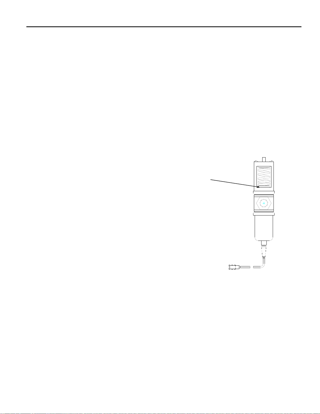
Water Regulating Valve
The water-regulating valve controls the head pressure by regulating the amount of
water flow through the condenser. The bellows of the regulating valve are
connected to the high-pressure side of the refrigeration system. As the head
pressure rises, the bellows expand increasing the water flow through the water
condenser. Adjusting the spring pressure screw on top of the water valve can vary
the rate of water flow. The valve should be adjusted to maintain a discharge
pressure of 250 psi (17.01 bar) on R404a units and 150 psi (10.21 bar) on R134a
units. Water exiting the condenser should be between 100°F (38°C) and 110°F
(43°C). When the machine is off, the water valve will close completely, stopping the
flow of water through the condenser. If the water flow does not stop when the
machine is off, the valve may need cleaning or replaced.
Air Cooled Condenser (Remote)
See Pages E5 and E7
High Pressure Safety Control (Manual Reset)
If the discharge pressure becomes excessive, the high-pressure safety
control will open and shut the machine off. The high-pressure safety control
opens at 450 psi (30.62 bar) on R404a units and 250 psi (17.01 bar) on
R134a units. The high-pressure safety control is used on all water-cooled and remote
units and select air-cooled units.
High Pressure Safety Control (Automatic Reset)
The automatic reset high pressure control opens at 450 psi (30.62 bar) and closes at
338 psi (23.00 bar). The high-pressure safety control is used on all water-cooled and
remote units and select air-cooled units.
Page E2
Page 52

ICE Series Refrigeration System
Thermostatic Expansion Valve (TXV)
The thermostatic expansion valve meters the flow of refrigerant into the
evaporator changing its state from a high-pressure liquid to a low-pressure
liquid. This drop in pressure causes the refrigerant to cool. The cooled
refrigerant absorbs heat from the water circulating over the evaporator. As
the evaporator fills with liquid refrigerant, the evaporator becomes colder.
The flow of refrigerant into the evaporator is controlled by the temperature at the outlet of the
evaporator. The expansion valve bulb, mounted to the top of the suction line, senses the
evaporator outlet temperature causing the expansion valve to open or close. As ice forms on the
evaporator, the temperature drops and the flow of refrigerant into the evaporator decreases,
resulting in a drop in suction pressure.
The evaporator should become completely flooded (filled with liquid refrigerant) during the freeze
cycle. A completely flooded evaporator will have a uniform freeze pattern (ice formation across the
evaporator). A starved evaporator (not enough liquid refrigerant) will have poor or no ice formation
at the top of the evaporator, and the tube(s) exiting the evaporator will not frost. All tubes should
be within 10 degrees of each other and frosted approximately 5 minutes from the start of the freeze
cycle.
An expansion valve that is restricted or not opening properly will starve the evaporator resulting in
lower than normal suction pressure. A low refrigerant charge will also starve the evaporator and
cause low suction and discharge pressures. If not sure of the amount of charge in the system, the
refrigerant should be recovered and the correct charge be weighed in before a defective valve can
be diagnosed.
If the evaporator is starved but the suction pressure is higher than normal, the TXV is not the
problem; refer to the troubleshooting tree in section C. If the TXV sticks open or if the thermal bulb
is not making good contact with the suction line, the flow of refrigerant into the evaporator will be
too great and liquid refrigerant will flood the compressor. The suction pressure will remain higher
than normal and the machine will remain in an extended freeze cycle. Ice will build evenly but will
be very thick.
Symptom Problem Possible Remedy
Evaporator flooded but suction 1 TXV thermal bulb not making 1 Tighten bulb clamp and
pressure not dropping. good contact with suction insulate bulb.
Compressor has been checked line or uninsulated
and appears to be good. 2 TXV bulb installed incorrect 2 Locate bulb on top of
Suction line at compressor may suction line
be colder than normal 3 System overcharged 3 Recharge system
4 TXV stuck open 4 Replace TXV
Evaporator starved, no frost 1 Machine low on charge 1 Recover refrigerant
on line(s) exiting evaporator. and weigh in proper
Suction pressure is low. charge
See Evap. Diagram Pg.E4 2 TXV restricted or stuck 2 Replace TXV and
closed drier
Continued Page E4
Page E3
Page 53

ICE Series Refrigeration System
Thermostatic Expansion Valve (Continued)
A dual evaporator machine will have one TXV for each evaporator. If one TXV sticks open and the
other is operating normally, the suction pressure will be higher than normal and both evaporators
will build thick ice. It is recommended that both valves be replace if one sticks open.
If one TXV sticks closed and one is operating normally, the suction pressure will be normal or low
but the evaporator with the defective valve will be starved (thick ice at the bottom and thin ice at
the top).
Evaporator
As water is circulated over the front of the evaporator, liquid refrigerant is circulated through the
tubing attached to the back of the evaporator. As the liquid refrigerant in the tubing vaporizes, it
absorbs heat from the water causing the water to freeze. The evaporator should be completely
flooded throughout most of the freeze cycle. A flooded evaporator will build ice evenly across the
evaporator. A starved evaporator will have uneven ice formation. Most problems with ice
formation or harvesting are not related to a defective evaporator, use the Troubleshooting Trees in
section C for additional help.
Refrigerant enters the evaporator through the bottom tube and exits through the top tube. On
(Prior to 0801) models ICE800, 1000, 1800 and 2100 the refrigerant line at the TXV outlet splits
into two feeder tubes. This split occurs at the distributor, which is a fitting that is soldered to the
TXV. One feeder tube from the distributor feeds the top of the evaporator; the other tube feeds the
bottom of the evaporator. The evaporator tubes run parallel, in opposite directions, along the back
of the evaporator creating a dual pass.
If the evaporator is flooded but not building ice evenly, it is possible the evaporator has coil
separation. Evaporator coil separation is the separation of the refrigerant tubing from the back of
the evaporator plate. This is very rare but occasionally occurs.
To confirm coil separation, remove and check the back of the evaporator. If the coil is separated,
the evaporator must be replaced. If the outlet(s) of the evaporator is not frosted, the problem is not
with coil separation (Refer to the troubleshooting trees, section C).
ICE800, 1000, 1800 and 2100 Prior to Jan, 2008
In
Out
In
Out
Out
In
Page E4
Page 54

ICE Series Refrigeration System
Note: Permanent discoloration of the evaporator plating is normal and will cause no problems with
harvesting the ice or sanitary conditions. Before condemning the evaporator for plating problems,
be certain it is not just discoloration. Good evaporators will not be covered under warranty. If the
spillway (plastic evaporator top) becomes damaged, it can be replaced. It is not necessary to
replace the entire evaporator.
As liquid refrigerant leaves the evaporator, it changes to a low-pressure gas before returning to the
compressor. Liquid refrigerant must not return to the compressor or damage will result. Frost on
the suction line at the inlet of the compressor indicates liquid returning to the compressor. Check
for frost at the end of the freeze cycle. If liquid is returning to the compressor, the problem must be
located and corrected. See Refrigerant Charge, Thermostatic Valve and Evaporator.
Harvest Cycle
Once the freeze cycle is complete, the machine enters the harvest cycle. The hot gas valve
opens to allow hot discharge gas to enter the evaporator.
Hot Gas Valve
When the machine enters harvest the hot gas valve coil is energized opening
the hot gas valve. Discharge gas is pumped through the hot gas valve directly
into the evaporator. The evaporator temperature will reach approximately 40°F
(4.5°C). The suction pressure during harvest should be a minimum of 70 psi
(4.8 bar) for R404a units or 50psi (3.4 bar) for R134a units. The discharge
pressure will drop during harvest.
If the hot gas valve does not completely open during harvest, there will not be enough hot gas in
the evaporator to defrost the ice. If there is not enough hot gas entering the evaporator, the
suction pressure will be lower than the above stated pressures. It is important when making this
check that the machine has the proper refrigerant charge, normal head pressure and the
compressor is functioning properly. If the hot gas valve leaks during the freeze cycle, ice will not
form on the top of the evaporator and suction pressure will be higher than normal. To check if the
hot gas valve is leaking, let the machine run in the freeze cycle for approximately 5 minutes. Now
feel the temperature between the inlet and outlet of the valve. A definite temperature difference
should be felt. If the lines are the same temperature and the suction pressure is higher than
normal; the valve is leaking and should be replaced. Use Troubleshooting Trees in section C.
Remote System
Machines that use remote condensers have several components that are not used in self
contained machines. A mixing valve controls the head pressure when the ambient temperature at
the condenser drops below 70°F (21°C). When the bin fills with ice or is turned off at the selector
switch, the machine will pump all the refrigerant into the receiver before shutting off.
Remote Condenser
For proper operation, the remote condenser must be installed properly.
Improper installation will void the warranty. See remote guidelines on page
A14. The location of the remote condenser should be such that the ambient
air temperature does not exceed 120°F (48.9°C). If ambient temperature
exceeds 120°F (48.9°C) ice production will decrease until the ambient
temperature decreases.
Air
Flow
Page E5
Page 55

ICE Series Refrigeration System
Remote Condenser (Continued)
If the airflow is restricted or the condenser is dirty, the head pressure will be excessively high, slow
production will result and the compressor may overheat and eventually become damaged. The
condenser coil and fan blades must be kept clean. The condenser can be cleaned with
compressed air or by using a brush. If a brush is used, brush in the direction of the fins taking care
not to bend the fins. If the condenser fins are bent, this will restrict the airflow through the
condenser and the fins will need to be straightened with a fin comb. Problems related to a dirty
condenser or poor airflow will not be covered under warranty. Note: The condenser fan motor runs
continually, it will shut off when the icemaker shuts off.
Mixing Valve
When the temperature at the condenser is above 70°F (21°C), the refrigerant flow from the
compressor is directed by the mixing valve through the condenser and into the receiver. When the
temperature at the condenser drops below 70°F (21°C), the pressure in the bellows of the mixing
valve becomes greater than the pressure of the liquid refrigerant coming from the condenser. This
change allows the valve to partially restrict the flow of
refrigerant leaving the condenser and allows discharge
gas to by-pass the condenser and flow directly into the
receiver, mixing with the liquid refrigerant from the
condenser. The amount of discharge gas that
bypasses the condenser increases as the ambient
temperature decreases. This action of the mixing
valve allows the discharge pressure to be maintained
at approximately 240 psi (16.5 bar) during low ambient
conditions. If the refrigerant system is undercharged
and the ambient temperature is below 70°F (21°C), the
mixing valve will not work properly. The mixing valve
will allow too much refrigerant to bypass the
condenser.
Problem Possible Cause Remedy
1 Head pressure low, Line between A. Valve Defective, not allowing A. Replace valve
valve and receiver cold. Ambient discharge gas into receiver
condenser temp. below 70°F (21°C)
2 Head pressure low, Line between A. System low on charge. A. Leak check. Recover
valve and receiver hot. B. Valve defective, not refrigerant and weigh
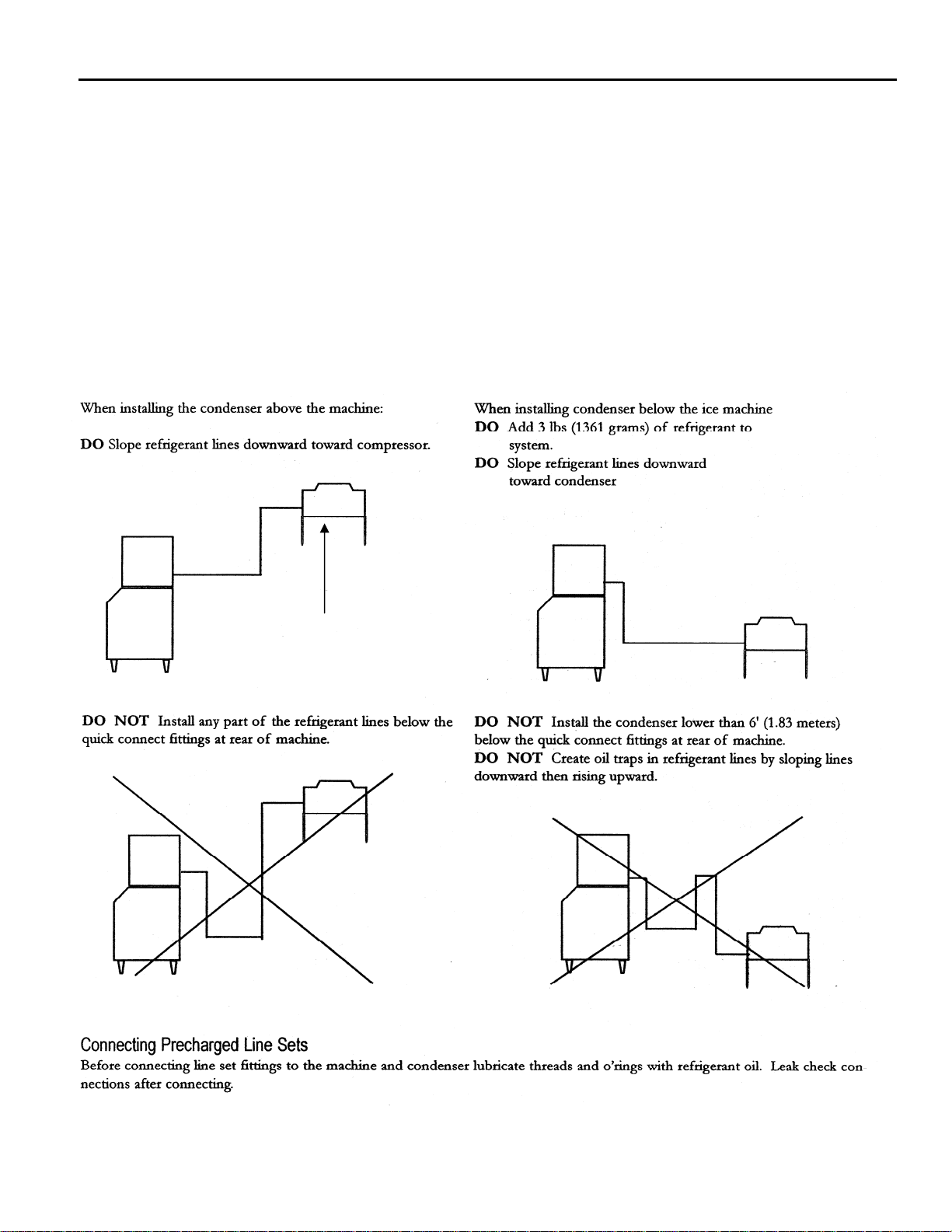
allowing liquid in proper charge.
into receiver. B. Replace valve
3. Head pressure low, Line A. Valve defective not A. Replace valve.
returning from condenser allowing refrigerant
is cool. Ambient condenser to circulate through
temperature is above 70°F (21°C) condenser.
Page E6
Page 56

ICE Series Refrigeration System
Pump Down System (Remote Only)
The pump down system prevents liquid refrigerant from migrating to the evaporator and compressor during the off cycle and prevents the compressor from slugging or starting under an excessive load.
Liquid Line Solenoid
When a machine with a remote condenser shuts off, the liquid line solenoid valve,
located at the outlet of the receiver, is de-energized causing the valve to close
completely restricting the flow of refrigerant. The compressor will pump all of the
refrigerant into the condenser and receiver.
As the system pumps down, the pressure on the low side of the system drops. When the suction
pressure drops to 10 psi (.68 bar), the pump down control opens and shuts the machine off. See
page F9 for pump down control operation. Liquid refrigerant is stored in the condenser and
receiver while the machine is off. It is normal for the machine to pump down once or twice an hour
as the pressures equalize.
When the machine comes back on (the bin switch closes or the selector switch placed to the ICE
position), the liquid line solenoid valve opens and the refrigerant is released from the receiver.
When the suction pressure rises to 35 psi (2.38 bar) the pump down control closes and the
machine comes back on. If the machine will not pump down, the valve may not be closing all the
way. A weak compressor will also prevent the machine from pumping down. Check for signs of a
weak compressor before replacing the liquid line solenoid. Prior to replacing the valve,
disassemble and check for obstructions that may not allow the valve to seat.
Receiver
If the system has a remote condenser, the refrigerant will enter a receiver before
passing through the filter drier. The receiver holds reserve liquid refrigerant during
the freeze cycle. The receiver also stores liquid refrigerant during the off cycle.
Page E7
Page 57

ICE Series Refrigeration System
Refrigerant
Refrigerant in a high-pressure liquid form is fed to an expansion valve where the refrigerant is
reduced to a low-pressure liquid. Under this low pressure, the liquid will absorb heat from the
evaporator causing the liquid to change to a vapor. This vapor is the drawn into the compressor
where the temperature and pressure of the vapor are increased. The high temperature, high
pressure vapor flows to the condenser where the heat is removed, causing the vapor to return to
the liquid form, making the refrigerant ready to flow back to the evaporator to pick up more heat.
Most Ice-O-Matic ice machine use R134a or R404a refrigerant. Always check the serial number
data plate for the proper type of refrigerant and the amount used in the machine you are servicing.
R404a and R134a are both HFC refrigerants, which result in no ozone depletion factor. R404a
cylinders are orange in color, R134a cylinders are light blue in color.
Important: When discharging refrigerant from an icemaker, recover as much of the
refrigerant as possible with a recovery device or some other means to prevent the
refrigerant from entering the atmosphere.
Method of Charging Refrigerant
In order to achieve a properly charged refrigeration system, the system must be completely
evacuated.
To achieve a complete evacuation you will need a service gauge manifold with properly maintained
hoses, and a vacuum pump capable of pulling a 50-micron vacuum. This will require a two-stage
pump.
Connect the service gauge manifold to the high and low side service ports and vacuum pump.
Make sure the valves on the gauge manifold are closed, then start the pump.
Note: Do not use a refrigeration compressor as a vacuum pump. Compressors are able to
pull only a 50,000-micron vacuum.
After the vacuum pump has been started, open the valves on the gauge manifold. This will allow
the refrigeration system to start being evacuated.
If there has not been an excessive amount of moisture in the system, allow the vacuum pump to
pull the system down to about 200 microns or 29.9 inches or less. Once this has been achieved,
allow the vacuum pump to operate for another 30 minutes. Then close the valves on the gauge
manifold and stop the vacuum pump. Then watch your gauges. A rise to 500 microns in three (3)
minutes or less indicates a dry system under a good vacuum.
If your gauge registers a more rapid rise, the system either has moisture remaining or there is a
leak in the system, requiring a check for the leak, and repair and another complete evacuation.
Note: Seal the ends of the gauge manifold hose and pull them into a deep vacuum to determine if
the leak is not in the hoses. The gauge manifold should be able to hold the vacuum for three (3)
minutes.
Page E8
Page 58

ICE Series Refrigeration System
If the refrigeration system is extremely wet, use radiant heat to raise the temperature of the
system. This action will cause the moisture to vaporize at less of a vacuum.
The use of two (2) valves, one between the vacuum pump and gauge manifold and the other
between the refrigerant cylinder and the gauge manifold allows you to evacuate and charge the
system without disconnecting any hoses. If the hoses were disconnected, air or moisture will have
the opportunity to enter the hoses and then the system.
A properly charged icemaker is a service technician’s greatest ally. Proper charging will allow any
concern with the icemaker to be accurately diagnosed.
The refrigerant charge must be weighed into the icemaker either by using a charging scale or with
a dial-a-charge.
The amount of proper refrigerant required for the icemaker is printed on the serial data plate
attached to the icemaker and is listed on the following pages. Never vary the amounts from those
listed.
Remote models with sixty (60) foot lineset runs will need an additional fifteen (15) ounces of
refrigerant added.
In some cases the complete refrigerant charge may not enter the refrigeration system. In those
instances, close the gauge manifold high side valve and disconnect the manifold from the high side
port.
When the icemaker is completely charged, secure the caps to the service ports and check to make
sure the ports are not leaking refrigerant.
Reference Tables on Page I6 and I16.
Page E9
Page 59

ICE Series Electrical System
g
Control Circuit
All machines in this manual are electro-mechanical controlled; however the control circuitry on the single evaporator units differs from the dual evaporator units and is detailed below.
Selector Switch
The selector switch is used to put the machine into the ICE making or WASH cycle or to turn the
machine OFF. The WASH position allows only the water pump to run and is used during the
cleaning process to circulate cleaning solution throughout the water system. When the selector
switch is turned to the ICE position, the machine begins the freeze cycle.
Contactor
When the selector switch is in the ICE position, the contactor coil is energized and
pulls in the contactor contacts. This energizes the compressor start components,
which starts the compressor.
Purge Switch
The purge switch is a momentary switch used to manually energize the purge valve. It is used
during the cleaning process to flush the cleaning solution from the water trough. The purge valve
will remain energized as long as the purge switch is depressed.
Note: Single Evaporator Units. The normally closed contacts of the purge switch also create a
circuit to relay 1. These contacts should remain closed unless the switch is depressed. If the
switch is defective and the normally closed contacts are open when the machine enters harvest,
the machine will return to freeze when the timer initiate control opens.
Compressor and Start Components
The compressor should run during the entire cycle. If the machine is in the ICE position but the
compressor is not running, check the compressor contactor to see if it is engaged. If the contactor
is not engaged, the problem is not with the compressor or the compressor start components. If the
contactor is engaged and there is correct voltage through the contactor, there could be a problem
with one of the starting components or the compressor. It is recommended that the compressor
starting components be replaced when replacing a compressor.
Compressor Check
If the compressor uses an
internal overload, be
certain that the compressor has cooled and the overload has reset before diagnosing the
compressor. If the compressor is cool and is still not running, check the compressor motor
windings by first removing the wires at the compressor terminals. With an ohmmeter, check for
continuity between all three terminals, if an open circuit exists between any of the terminals, the
compressor may need to be replaced. Check for continuity from each terminal to the compressor
body, if continuity is found from any terminal to the compressor body, the compressor windings are
shorted to ground and the compressor will need to be replaced. If the compressor appears to be
good at this point, it is advisable to use a compressor analyzer to isolate the compressor from the
start components while checking for a locked rotor. If an analyzer is not available, the compressor
starting components must be checked.
Disconnect power before servicin
Page F1
Page 60

ICE Series Electrical System
Compressor Check (Continued)
If all starting components are good, check the voltage from the common terminal of the
compressor, making sure proper voltage is supplied to the compressor and all wiring is properly
connected. If the compressor does not start and there is excessive amperage draw, (see locked
rotor amps on compressor tag) the compressor has a locked rotor and should be replaced.
Important: Compressors returned to the factory for warranty are tested and will not be covered
under the warranty policy if they are not defective.
Overload (External)
If there is no amperage draw check the compressor overload. The compressor overload can be
checked for continuity after removing it from the compressor and letting it cool to room
temperature. If there is no continuity between the two terminals, replace the overload. If the
overload is suspected of opening prematurely, it should be replaced with an overload, which is
known to be good.
Capacitors
The start capacitor is an electrical storage device used to provide starting torque to the
compressor. If a start capacitor is defective, the compressor will not start properly.
The run capacitor is an electrical storage device used to improve the running characteristics and
efficiency of the compressor.
Before checking a capacitor, it should be discharged by shorting across the terminals. If a run or
start capacitor is cracked, leaking or bulging it should be replaced. If a capacitor is suspected of
being defective, it can easily be checked by replacing it with a capacitor of the correct size, which
is known to be good. If the compressor starts and runs properly, replace the original capacitor. A
capacitor tester can also be used.
Start Relay
The start relay breaks the electrical circuit to the start windings when the compressor motor speed
increases. If the relay is defective, the compressor will not start or it may start but will run for a
very short time.
A compressor relay can be checked by removing the relay and checking the relay contacts for
damage and check for continuity across the closed relay points. Check the relay coil with an
ohmmeter. If no continuity is read, replace the relay.
Page F2
Page 61

ICE Series Electrical System
Untimed Freeze Cycle
During the freeze cycle the compressor, water pump and condenser fan motor(s) (if used) are
running. On remote systems the liquid line solenoid is also energized, see Refrigeration System.
As ice forms on the evaporator, the suction pressure drops. The machine is in the untimed portion
of the freeze cycle and will remain in untimed freeze until the suction pressure drops low enough to
close the timer initiate control. See page I1-I6 for operating pressures.
Timer Initiate
The timer initiate is a low-pressure control that closes (cut in) on a drop in suction pressure. When
the timer initiate control closes, the freeze timer is energized and the machine enters the timed
portion of the freeze cycle. When the machine enters harvest, the suction pressure rises and
opens the control. The timer initiate control should be adjusted per the chart on page I1-I6.
The timer initiate is factory set and does not normally need to be adjusted. If the ice bridge
thickness is incorrect, the freeze timer should be adjusted rather than the timer initiate. See page
F4 for freeze timer adjustment procedure. The timer initiate may need to be adjusted if excessive
time (more than 7 minutes) is needed on the timer to achieve proper bridge thickness of if very little
time (less than 1 minute) is needed on the timer to achieve proper bridge thickness.
If the timer initiate is suspected of being out of adjustment or not operating properly, check the
control as follows. Make sure the high temperature safety control is not open, see page F8. Turn
the machine off and disconnect incoming power by unplugging the machine or switching the circuit
breaker OFF. Attach one lead of a voltmeter to terminal 1 and the other lead to terminal 2 of the
timer initiate control. Reconnect incoming power and turn the machine to the ICE position.
Connect a low pressure gauge to the machine. The volt meter should read line voltage until the
timer initiate control closes at which point the voltmeter should read zero volts. Note the suction
pressure at this point. Adjust the timer initiate if necessary. Turning the adjustment screw counter
clockwise will lower the cut in pressure, turning the adjustment screw
clockwise will raise the cut in pressure. The differential is preset and
does not require adjustment. If the control cannot be adjusted to the
correct pressure setting or if the cut in point is erratic the control must be
replaced. If the suction pressure is not dropping properly, see the
Troubleshooting Tree “Machine Does Not Enter Harvest” in Section C.
Relay 1
Relay 1 is used to energize the fan motor on air-cooled units. The fan is energized through the
common and normally closed contacts.
Relay 2 (Note: Relay 2 is not used on Undercounter models)
On single evaporator machines, relay 2 is used only to bypass the bin control during the freeze
cycle and the first part of the harvest cycle. Relay 2 is energized through the normally closed
contacts of the cam switch at the beginning of the freeze cycle. When energized, Relay 2 will
prevent the machine from shutting off if the bin switch opens. The relay will remain energized until
the cam switch is lifted onto the high part of the cam during harvest. At this time the machine will
shut off if the bin switch is open.
Relay 3 and Relay 4 (ICE1506 Applications) Relay 3 and Relay 4 bypass the bin switches to
allow the curtains to open and close during the freeze cycle on an ice dispenser application. This
will prevent the ice machine from shutting off during dispenser agitation.
Adjustment Screw
Page F3
Page 62

ICE Series Electrical System
Timed Freeze
When the freeze timer is energized, the machine
is in the timed portion of the freeze cycle. The
freeze timer will time out the remainder of the
freeze cycle. Once the time has passed, the
machine will enter the harvest cycle.
Freeze Timer
The freeze time is an adjustable timer used to
control the ice bridge thickness. The freeze timer
is factory set but may need to be adjusted upon
initial start up of the machine. When time is
added to the freeze timer, the length of the freeze
cycle is increased, therefore the ice bridge
thickness is increased. When time is removed
from the timer, the freeze cycle is decreased and
the ice bridge thickness is decreased.
The freeze timer can be adjusted by sliding one
or more switches to either the ON or OFF
position to obtain the setting which will produce
the proper bridge thickness. A timer setting of 128 and 256
switched ON will provide an initial timer setting.
The ice bridge thickness should be approximately 3/16”
(5mm) on the ICEU undercounter series, ICE0250 and
ICE0305, and 1/8” (3 mm) on ICE0400 and larger units.
If the bridge is too thick, remove enough time from the
timer to achieve proper thickness. If the bridge is too
thin, add enough time to the timer to achieve proper
thickness.
Check the freeze timer for proper operation as follows: Make sure that the high temperature safety
control is not open, see page F8. Turn the machine OFF and disconnect the incoming power by
unplugging the machine or switching the circuit breaker OFF. Attach one lead of a voltmeter to
terminal 1 and the other lead to terminal 3 of the timer.
Reconnect incoming power and turn the machine to the ICE position. The volt meter should read
zero volts until the timer initiate closes at which point the timer will energize and line voltage should
be read.
When the timer counts out, the voltmeter will again read zero volts. The time it takes the freeze
timer to time out, once it has been energized should match the timer adjustment. If it does not or if
the timer never closes, the timer is defective.
Note: The hot gas delay timer utilized on the ICE1400, ICE1506, ICE1606, ICE1800 and
ICE2100 Series cubers should always be set at 4 seconds. (Not applicable on Version 3 & 4)
Sample Timer
Combine time in seconds
Bridge Thickness
Page F4
Page 63

ICE Series Electrical System
Harvest Cycle
Single Evaporator Machines
Once the freeze timer has timed out, power is sent to relay 1 and the machine enters the harvest
cycle. Once in harvest motor, the purge valve, hot gas valve and harvest motor are energized.
The water pump continues to run during the first part of the harvest cycle so that mineral laden
water remaining in the water trough can be pumped through the purge valve to the drain. The
harvest motor turns the clutch assembly to actuate the cam switch.
The cam switch is in the normally closed position during freeze and at the beginning of harvest.
Once the clutch turns far enough to actuate the cam switch, the water pump and purge valve is deenergized. The harvest motor continues to turn the clutch. When the cam switch returns to the
normally closed position, the machine returns to the freeze cycle.
If the bin switch is open when the cam switch is actuated by the high part of the cam, the machine
will shut off. Remote units pump down before shutting off.
Relay 1
When relay 1 is energized, the normally open contacts (1-B) close sending power to the hot gas
valve and harvest motor and (1-A) close sends power to the purge valve and the coil of relay 1 to
keep the coil energized when the timer initiate opens. The fan motor on self contained air cooled
model are wired through the NC contacts of relay 1, when the contacts open during harvest, the
condenser fan motor is de-energized.
Relay 2 See Page F4.
Dual Evaporator Machines (Prior to Jan 08)
Once the freeze timer has counter out, power is sent to: (A) harvest motor 1 and relay coil 1
through the normally closed contacts of cam switch 1, (B) to harvest motor 2 and relay coil 2
through the normally closed contacts of cam switch 2. The contacts of relay 1B and 2B closing,
energizes the 4-second hot gas delay timer (Right Hand Timer)
This 4-second delay will allow the harvest motors to rotate and allow the cam switches to switch to
the normally open position before the low-pressure control opens during hot gas. The cam
switches are now in the normally open position and will continue to energize the harvest motors
and relays until the cam rotates and the switch returns to the normally closed position.
Once the 4-second delay timer has timed out, the hot gas valves and purge valve will energize
and allow hot gas into the evaporators. The bin control switches are by passed through the
normally open contacts of relay 1A and 2A.
The bin switches are bypassed to allow the cam switch to return to the normally closed position
prior to the machine shutting down if the curtain is open. Each harvest assist motor will only make
one revolution prior to shutting down on full bin or advancing to the next freeze cycle.
Both hot gas valves and the water purge valve remain energized until both harvest assist motors
complete one revolution. The water pump is energized throughout the harvest cycle. The unit will
shut down if the curtains are open during the freeze cycle. Remote units pump down before
shutting off. The fan motors on self contained air cooled model are wired through the NC contacts
of relay 1B, when the contacts open during harvest, the condenser fan motors are de-energized.
Page F5
Page 64

ICE Series Electrical System
Harvest Assist Assembly
The harvest assist assembly
has several purposes: to assist
in moving the ice off of the
evaporator, to control the
length of harvest and to
terminate harvest. When the
machine enters harvest, power
is sent to the harvest motor
which turns a slip clutch. A
probe is attached to the
rotating clutch and is pushed
against the back of the ice
slab. The clutch begins to slip
when the probe applies
approximately 25 ounces of
pressure against the ice slab.
It takes approximately 1 minute
for hot gas to heat the evaporator enough to loosen the ice from the evaporator plate. At this point
the clutch pressure overcomes the capillary attraction of the ice to the evaporator plate and the ice
begins to move off of the evaporator. As the ice is being pushed, the clutch stops slipping and
begins to turn, extending the probe enough to push the ice completely off of the evaporator.
Harvest Motor
The harvest motor is energized at the beginning of harvest and will remain energized until the
machine returns to the freeze cycle. A defective harvest motor will usually not run. The harvest
motor rotates in a clockwise direction. It is possible for a defective motor to run backwards
(counterclockwise). If this happens the motor must be replaced. It is also possible for a defective
motor to “bump” backwards immediately when entering harvest. This will activate the cam switch
and cause the machine to return to the freeze cycle immediately after entering harvest. If the
machine is in harvest only for a split second, the harvest motor may be defective. Verify the motor
is defective by watching the clutch closely when the machine enters harvest.
Clutch Assembly
The clutch assembly consists of a slip clutch and cam. A probe is attached to the clutch assembly
and the harvest motor turns the clutch during harvest. As the harvest motor turns, the clutch will
slip while the probe is pushed against the ice. The clutch will continue to slip as long as the
pressure required to move the ice is greater than the 25 oz. Once the evaporator has heated
enough to break the bond of ice to the evaporator, the pressure required to move the ice becomes
less than the 25 oz. And the clutch begins to move.
The clutch assembly is not adjustable. If the clutch tension is weak (less than 25 oz.) a slow
harvest or excessive ice meltage during harvest will result. If the clutch pressure becomes too
tight, the force of the probe against the back of the ice may cause the slab to break and the ice
may not fall off of the evaporator. If the clutch tension is suspected of being too tight or loose, turn
the clutch by hand. The clutch should turn smoothly without “grabbing”, but should offer some
resistance. If in doubt as to whether or not the clutch is defective, compare the tension with one
that is known to be good.
Page F6
Page 65

ICE Series Electrical System
Probe Tip and Swivel
The probe tip is attached to the clutch and makes contact with the back of the ice slab during
harvest. The swivel allows the probe tip to pivot as the clutch turns so that the probe is pushed
straight through the evaporator probe guide.
The tip of the probe should be flush with the back of the evaporator or recessed up the 1/16 of an
inch (.16cm). The probe tip must not extend into the freezing area of the evaporator during freeze.
(Note: Units manufactured after June 2004 utilize a non adjustable probe.)
The length of the probe is adjustable by loosening the locknut and adjusting the probe in or out of
the swivel. Once the probe has been adjusted to the proper length, tighten the locknut. If the
probe tip binds during operation it may cause the clutch to slip unnecessarily. This may occur if
the harvest motor mounting bracket is not aligned properly or if the probe tip has excessive mineral
deposits on it. Remove and clean the probe if necessary.
To check the probe tip for binding, remove the shoulder bolt holding the swivel to the clutch and
simulate the movement of the swivel and probe by moving the swivel in a circular motion around
the outer portion of the clutch. The swivel should also move freely. If any resistance is felt the
bracket should be adjusted by loosening the bracket mounting screws and repositioning the
bracket until the probe moves freely.
Cam Switch Operation-Single Evaporator Machines
The actuator arm of the cam switch rides on the edge of the clutch assembly and is actuated by
the high and low portion of the cam. When the machine is in the freeze cycle the actuator arm of
the cam switch is in the low part of the cam. During freeze, power is supplied to the water pump
and relay 2, through the normally closed contacts of the cam switch. When the machine enters
harvest, power is supplied to the water pump and purge valve through the normally closed
contacts of the cam switch and through the normally open contacts of relay 1 (closed during
harvest). The water pump, purge valve and relay 1 remain energized until the cam switch is lifted
on to the high part of the cam. Relay 2 will also de-energize at this time allowing the machine to
shut off if the bin switch opens. Undercounter machines manufactured after July of 2004 will have
the water pump run continually until the machine shuts down.
Cam Switch Operation-Dual Evaporator Machines (Prior to January 2008)
Once the freeze timer has counted out, power is sent to: (A) harvest motor 1 and relay coil 1
through the normally closed contacts of cam switch 1, (B) to harvest motor 2 and relay coil 2
through the normally closed contacts of cam switch 2.
This 4-second delay will allow the harvest motors to rotate and allow the cam switches to switch to
the normally open position before the low-pressure control opens during hot gas. The cam
switches are now in the normally open position and will continue to energize the harvest motors
and relays until the cam rotates and the switch returns to the normally closed position.
The bin switches are bypassed to allow the cam switch to return to the normally closed position,
prior to the machine shutting down if the curtain is open. Each harvest assist motor will only make
one revolution prior to shutting down on full bin or advancing to the next freeze cycle.
Both hot gas valves and the water purge valve remain energized until both harvest assist motors
complete one revolution. The water pump is energized throughout the harvest cycle. The unit will
shut down if the curtains are open during the freeze cycle.
Page F7
Page 66

ICE Series Electrical System
Cam Switch Adjustment
Check the cam switch for proper adjustment by slowing turning the clutch by hand in a
counterclockwise direction while listening for the switch contacts to change. The switch should
have an audible “click” as the roller reaches the high part of the cam. Now slowly turn the clutch in
a clockwise direction and the switch should have an audible “click” as the roller reaches the low
part of the cam. Adjust the switch by loosening the mounting screws and moving the position of
the switch. If the cam switch is suspected of being defective it should be checked with an
ohmmeter. It should not be assumed that the switch is good because a “click” can be heard
when moving the actuator arm.
High Temperature Safety Control
The high temperature safety control is a thermal disc that protects the
machine if the machine “sticks” in the harvest cycle. The high temperature
safety is clamped to the suction line near the expansion valve thermal bulb.
It opens when the suction line temperature reaches 120ºF (48.8ºC) and closes when the
temperature drops to 80ºF (26.6ºC). If the high temperature safety opens during harvest, it will
de-energize the harvest components. If the high temperature safety is defective and fails open
during the freeze cycle, it will not allow the relay(s) to energize and the machine will not enter
harvest. Remove the high temperature safety control and check it with an ohmmeter to verify that
it is defective.
Note 1: ICE0500R3, ICE0606R3, ICE0806R3 and ICE1006R3: The high temperature safety
control specifications have been changed to open at 120ْ F and close at 100ْ F.
Note 2: On models where the high temperature safety control is mounted on the hot gas valve
outlet tube, the specifications are open at 180ºF and close at 120 ºF.
Additionally the high temperature safety control is wired in series with the contactor. If the
high temperature safety control opens for any reason, the compressor will shut down.
This is an automatic reset control. Do not allow the machine to operate without the
high temperature safety control. Damage to the machine may result and the
warranty will be void.
Bin Control Operation
The bin control is used to shut the machine off when the bin fills with ice. The bin control must be
checked upon installation or initial start-up and when performing maintenance. Adjustments are
not covered under warranty.
There is one bin switch for each evaporator. The actuator arm of the bin switch comes in contact
with the splash curtain. When the bin is full of ice, the splash curtain is held open when ice drops
off of the evaporator. This releases the pressure of the bin switch actuator arm allowing the switch
to open.
Single evaporator machines: If the bin switch opens during freeze, or the first part of harvest,
relay 2 bypasses the bin switch and the machine will continue running. If the bin switch is opened
during harvest, when the cam switch is lifted onto the high part of the cam, the machine will shut
off. When the bin switch closes again, the machine will restart.
Dual evaporator machines: If either bin switch opens during the freeze cycle, the machine will
shut off. Relay 1 and relay 2 will bypass the bin switches during defrost. If either bin switch is
open when the machine returns to the freeze cycle, the machine will shut off.
Page F8
Page 67

ICE Series Electrical System
Undercounter machines: A thermostatic bin control is used on the undercounter models. The bin
thermostat is located in the control box with a capillary tube, which is in a brass thermo-well
mounted to the water trough. When ice comes in contact with the capillary tube thermo-well, the
bin thermostat opens and the machine will shut off.
Bin Control Adjustment
All Models (Except Undercounter Models): Check the bin switch for proper adjustment by
swinging the bottom of the curtain away from the evaporator. Slowly bring the curtain towards the
evaporator. The switch should close when the bottom edge of the curtain is even with the outer
edge of the water trough. Adjust the switch by loosening the screws the hold the switch in place.
Move the switch to the proper position and retighten the screws. Recheck the adjustment.
Adjustments are not covered under warranty.
Undercounter Models and ICE1506R
Hold ice against the brass thermal-well making sure the ice is in contact with at least 6 inches (15
cm) of the thermal-well. The bin control should open in approximately 1 minute. Remove the ice.
The bin control should close in approximately 3 minutes. If a major adjustment is required, turn the
adjustment screw counterclockwise (warmer) until it stops then turn the adjustment screw
clockwise (colder) 1/8 of a turn. This should put the control close to the proper adjustment,
recheck and make a minor adjustment if needed. If a minor adjustment is required, turn the
adjustment screw clockwise (colder) or counterclockwise (warmer). Adjustments are not covered
under warranty.
Pump Down System (Remote Only)
If a remote machine is shut down by the selector switch or bin control, the liquid line solenoid valve
is de-energized allowing the valve to close. This blocks the flow of refrigerant causing all the
refrigerant to be pumped into the receiver and condenser. This is done to prevent liquid refrigerant
from migrating into the compressor during the off cycle, which could damage the compressor on
start-up. Also see Pump Down System in the Refrigeration Section on page E7. As the refrigerant
is pumped into the receiver, the suction pressure begins to drop. Once the suction pressure
reaches approximately 10 psi (.68 bar) the pump down control contacts open, which will deenergize the compressor contactor. When the machine is turned back on, power is supplied to the
liquid line solenoid which opens the valve and allows the suction pressure to rise enough to close
the pump down controls contacts.
Pump Down Control
The pump down control is a low pressure control that shuts the machine off when the
suction pressure drops during the pump down phase. The control is factory set to open at
10 psi (.68 bar) and close at 30 psi (2.04 bar). The pump down control does not normally
need to be adjusted, however an adjustment may be made by turning the adjustment
screw. Note: Later model machines have a non adjustable pump down control.
Fan Control
On models utilizing a fan control, the fan will cycle on at 250 psi (17.01) and
cycle off at 200 psi (13.61 bar).
Page F9
Page 68

ICE Series Electrical System
Electrical Sequence for the ICE1400 Series Version 3&4, ICE1800 Series Version 3&4 and
the ICE2100 Series Version 3&4 Cubers. (Manufactured from January, 2008)
ICE1400A/W3&4, 1800W3&4 and 2100W3&4 Electrical Sequence (Includes 50 hz. And 3
Phase)
1. Suction Pressure starts out at approx 60 psi and slowly drops to close the LP Control.
2. The LP Control energizes Relay Number 2 Coil.
3. Relay Number 2A contacts C and NO close to bypass the bin switches, Relay Number 2B
contacts close and energize the timer.
4. The Timer times out and energizes Relay Number 1 Coil.
5. Relay Number 1A contacts C and NO close to send power to Cam Switch Number 2 contacts C
and NC which energizes Harvest Motor 2, Hot Gas 2 and Relay Number 3 Coil.
6. Relay Number 1B contacts C and NO close to energize Harvest Motor 1 and Hot Gas 1
7. Relay Number 1B contacts C and NC open to de-energize the fan motors.
8. When the LP Control opens during hot gas, the circuit is latched through the Purge Switch
contacts C and NC.
9. Relay Number 3A contacts C and NO close to send power to the Selector Switch and Hot Gas
Valves when the curtain is open.
10. Once Cam Switch 2 contacts C and NO close (High Side of the Cam) it will remain energized
from the Selector Switch until contacts C and NC close. (Rotates 360 degrees)
11. Once Cam Switch 1 contacts C and NO close (High Side of the Cam) the Harvest Motor will be
energized and the Water Pump and Purge Valve will be de-energized when contacts C and NC
open.
12. With the bin switches open, Relay Number 3 Coil de-energized due to Cam Switch 2 contacts
C and NC closing, the unit will shut off on full bin.
Notes:
●C=Common
●NC=Normally Closed
●NO-Normally Open
●Relay Number 9 & 12=Common
●Relay Number 1 & 4=Normally Closed
●Relay Number 5 & 8=Normally Open
●The Fan Control on the air cooled model cycles only one fan.
●Relay 1, Puts unit into defrosts.
●Relay 2, Bypasses the Bin Switches and initiates the Timer.
●Relay 3, Bypasses the bin Switches during harvest when Relay 2 is de-energized from a rise in
the suction pressure opening the Low Pressure Control.
Page F10
Page 69

ICE Series Electrical System
Electrical Sequence for the ICE1400 Series Version 3&4, ICE1800 Series Version 3&4 and
the ICE2100 Series Version 3&4 Cubers. (Manufactured from January, 2008)
ICE1400R3&4, 1800R3&4 and 2100R3&4 Electrical Sequence (Includes 50 hz. And 3 Phase)
This unit incorporates a timer upstream of the Low Pressure Control for Low Ambients.
1. Timer number 2 (Six Minutes) is energized from the Selector Switch through Relay Number 3B
contacts C and NC.
2. Timer Number 2 (Six Minutes) times out and energizes Relay Number 2 Coil.
3. Relay Number 2B contacts C and NO close which energizes the Low Pressure Control.
4. The Low pressure Control closes and energizes Timer Number 1.
5. The Timer times out and energizes Relay Number 1 Coil.
6. Relay Number 1A contacts C and NO close to send power to Cam Switch Number 2 C and NC
which energizes Harvest Motor 2, Hot Gas Valve 2 and Relay Number 3 Coil.
7. Relay Number 1B contacts close to energize Harvest Motor 1 and Hot Gas Valve 1.
8. When the Low Pressure Control opens during hot gas defrost, the circuit is latched through the
Purge Switch contacts C and NC.
9. Relay Number 3A contacts C and NO close to send power to the Selector Switch and Hot Gas
Valves when the curtain is open.
10. Once Cam Switch 2 contacts C and NO close (High side of the Cam) it will remain energized
from the Selector Switch until contacts C and NC close. (Rotates 360 degrees)
11. Once Cam Switch 1 contacts C and NO close (High Side of the Cam) the Harvest Motor will be
energized and the Water Pump and Purge Valve will be de-energized when contacts C and NC
open.
12. With the bin switches open, Relay Number 3 Coil de-energized due to Cam Switch 2 contacts
C and NC closing, the unit will shut off on full bin.
Notes:
●C=Common
●NC=Normally Closed
●NO-Normally Open
●Relay Number 9 & 12=Common
●Relay Number 1 & 4=Normally Closed
●Relay Number 5 & 8=Normally Open
●Relay 1, Puts unit into defrosts.
●Relay 2, Bypasses the Bin Switches and initiates the Low Pressure Control
●Relay 3, Bypasses the Bin Switches during harvest when Relay 2 is de-energized from a rise in
the suction pressure opening the Low Pressure Control and energizes Timer Number2
Page F11
Page 70

ICE Series Electrical System
Electrical Sequence for theICE1506 Series Version 3 (Manufactured from January, 2008)
This unit incorporates a timer upstream of the Low Pressure Control for Low Ambients.
1. When the Selector Switch is set to ICE, Relay Number 2 Coil is energized through Cam Switch
contacts C and NC (Bypasses the Bin Controls)
2. Relay Number 4B contacts C and NC energize Timer Number 2 (6 Minutes)
3. Timer number 2 times out and energizes Relay Number 3 Coil.
4. Relay Number 3B contacts C and NO close and energizes the Low Pressure Control.
5. The Low Pressure Control closes to energize Timer Number 1.
6. Timer Number 1 times out and energizes Relay Number 1 Coil
7. Relay Number 1A contacts C and NO close and send power Cam Switch Number 2 C and NC
which energizes Harvest Motor 2, Hot Gas valves and Relay Number 4 Coil.
8. Relay Number 1B contacts C and NO close to energize Harvest Motor 1 and Hot Gas Valve 1.
9. When the Low Pressure Control opens during hot gas, the circuit is latched through the Purge
Switch contacts C and NC.
10. Once Cam Switch 2 contacts C and NO close (High side of the Cam) it will remain energized
from the Selector Switch until contacts C and NC close (Rotates 360 degrees)
11. Once Cam Switch 1 contacts C and NO close (High side of the Cam) the Harvest Motor will be
energized and the Water Pump, Purge Valve and Relay Number 2 Coil will be de-energized
when contacts C and NC open.
12. When Relay Number 2 Coil is de-energized and if the curtain switches or bin stat are open, the
unit will pump down and shut off on full bin.
Notes:
●C=Common
●NC=Normally Closed
●NO-Normally Open
●Relay Number 9 & 12=Common
●Relay Number 1 & 4=Normally Closed
●Relay Number 5 & 8=Normally Open
●Relay 1, Puts unit into defrosts.
●Relay 2, Bypasses the Bin Switches.
●Relay 3,Energizes the Low Pressure Control
●Relay 4,Resets Timer Number 2
Page F12
Page 71

ICE Series Notes
Table of Contents
Table of Contents Page A1
General Information
How To Use This Manual Page A2
Model And Serial Number Format Page A3
Electrical And Mechanical Specifications Page A5-A8
Installation Guidelines Page A9
Electrical And Plumbing Requirements Page A10-A17
Remote Condenser Installation Page A18-A19
How The Machine Works Page A20
Undercounter Model Bin Removal Page A21-A22
Warranty Information Page A23-A24
Scheduled Maintenance
Maintenance Procedure Page B1
Cleaning and Sanitizing Instructions Page B1-B2
Winterizing Procedure Page B3
Cabinet Care Page B4
Troubleshooting Trees
How to Use The Troubleshooting Trees Page C1
Troubleshooting Trees Table Of Contents Page C2
Troubleshooting Trees Page C3-C18
Water System
Water Distribution And Components Page D1-D5
Refrigeration System
Refrigeration Cycle And Components Page E1
Harvest Cycle Page E5
Remote System Page E5-E6
Pump Down System Page E7
Refrigerant Specifications Page E8-E20
Electrical System
Control Circuit Page F1
Compressor And Start Components Page F1-F2
Untimed Freeze Cycle Page F3
Timed Freeze Cycle Page F4
Harvest Cycle Page F5-F9
Pump Down System Page F9
Wiring Diagrams Page G1
Page 72

ICE Series Wiring Diagram
ICEU150/200/205/206 Air and Water Wiring Diagram
Page G1
Page 73

ICE Series Wiring Diagram
ICEU150/200/205/206 Air and Water Wiring Schematic
Page G2
Page 74

ICE Series Wiring Diagram
ICEU150/220/225/226 Air and Water Wiring Diagram
Page G3
Page 75

ICE Series Wiring Diagram
ICEU150/220/225/226 Air and Water Wiring Schematic
Page G4
Page 76

ICE Series Wiring Diagram
ICE0250 Air and Water Wiring Diagram
Page G5
Page 77

ICE Series Wiring Diagram
ICE0250 Air and Water Wiring Schematic
Page G6
Page 78

ICE Series Wiring Diagram
ICE0400 Air and Water Wiring Diagram
Page G7
Page 79

ICE Series Wiring Diagram
ICE0400 Air and Water Wiring Schematic
Page G8
Page 80

ICE Series Wiring Diagram
ICE0405/0406 Air and Water Wiring Diagram
Page G9
Page 81

ICE Series Wiring Diagram
ICE0405/0406 Air and Water Wiring Schematic
Page G10
Page 82

ICE Series Wiring Diagram
ICE0500 Air and Water Wiring Diagram
Page G11
Page 83

ICE Series Wiring Diagram
ICE0500 Air and Water Wiring Schematic
Page G12
Page 84

ICE Series Wiring Diagram
ICE0500 Remote Wiring Diagram
Page G13
Page 85

ICE Series Wiring Diagram
ICE0500 Remote Wiring Schematic
Page G14
Page 86

ICE Series Wiring Diagram
ICE0605/0606/0805/0806/1005/1006 Air and Water Wiring Diagram
Page G15
Page 87

ICE Series Wiring Diagram
ICE0605/0606/0805/0806/1005/1006 Air and Water Wiring Schematic
Page G16
Page 88

ICE Series Wiring Diagram
ICE0605/0606/0805/0806/1005/1006 Remote Wiring Diagram
Page G17
Page 89

ICE Series Wiring Diagram
ICE0605/0606/0805/0806/1005/1006 Remote Wiring Schematic
Page G18
Page 90

ICE Series Wiring Diagram
ICE1007 Air and Water Wiring Diagram
Page G19
Page 91

ICE Series Wiring Diagram
ICE1007 Air and Water Wiring Schematic
Page G20
Page 92

ICE Series Wiring Diagram
ICE1007 Remote Wiring Diagram
Page G21
Page 93

ICE Series Wiring Diagram
ICE1007 Remote Wiring Schematic
Page G22
Page 94

ICE Series Wiring Diagram
ICE1405/1406/1806/2005/2106 Air and Water Wiring Diagram
Page G23
Page 95

ICE Series Wiring Diagram
ICE1405/1406/1806/2005/2106 Air and Water Wiring Schematic
Page G24
Page 96

ICE Series Wiring Diagram
ICE1405/1406/1806/2005/2106 Remote Wiring Diagram
Page G25
Page 97

ICE Series Wiring Diagram
ICE1405/1406/1806/2005/2106 Remote Wiring Schematic
Page G26
Page 98

ICE Series Wiring Diagram
ICE1407/1807/2107 Air and Water Wiring Diagram
Page G27
Page 99

ICE Series Wiring Diagram
ICE1407/1807/2107 Air and Water Wiring Schematic
Page G28
Page 100

ICE Series Wiring Diagram
ICE1407/1807/2107 Remote Wiring Diagram
Page G29
 Loading...