

Page 1
Page 2

TABLE OF CONTENTS PAGE
GENERAL INFORMATION AND INSTALLATION 1
Introduction 1
Unpacking and inspection 1
Location and levelling 1
Electrical connection 2
Water supply and drain connection 2
Final check list 3
Installation practice 3
OPERATING INSTRUCTIONS 4
Start up 4
Operational checks 4
a)
OPERATING PRINCIPLES 6
Freezing cycle 6
Harvest cycle 6
CLEANING INSTRUCTIONS OF WATER SYSTEM 9
Page 3
A B
ICEU 045 - 065
b)
C
A
B
C
ICEU 105
A
B
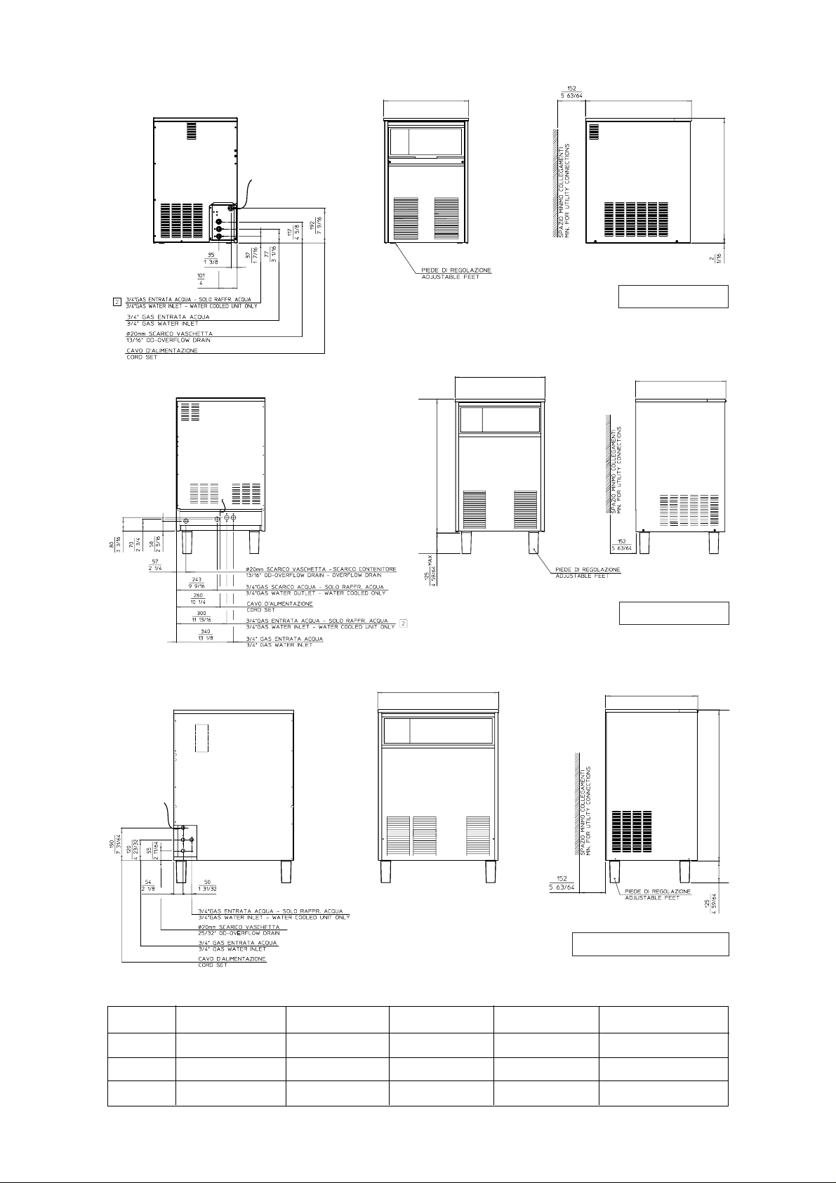
ICEU 085 - 145 - 185
ICEU 045 ICEU 065 ICEU 085 ICEU 105 ICEU 145 - 185
A 389 mm 465 mm 529 mm 529 mm 699 mm
B 515 mm 586 mm 525 mm 535 mm 536 mm
C 640 mm 690 mm 815 mm 796 mm 885 mm
C
Page 4
c)
Page 5

TECHNICAL SPECIFICATIONS - SPECIFICHE TECNICHE - DONNÉES TECHNIQUE - TECHNISCHE ANGABEN
d)
Electric voltage
Alimentazione elettrica 230/50/1 230/50/1 230/50/1 230/50/1 230/50/1 230/50/1
Alimentation électrique -10 ÷ +10% -10 ÷ +10% -10 ÷ +10% -10 ÷ +10% -10 ÷ +10% -10 ÷ +10%
Netzspannung
Condensation Air Water Air Water Air Water Air Water Air Water Air Water
Condensazione Aria Acqua Aria Acqua Aria Acqua Aria Acqua Aria Acqua Aria Acqua
Condensation Air Eau Air Eau Air Eau Air Eau Air Eau Air Eau
Kühlung Luft Wasser Luft Wasser Luft Wasser Luft Wasser Luft Wasser Luft Wasser
Bin capacity (kg)
Capacità contenitore (kg)
Capacité bac glaçons (kg) 8 15 16 18 18 30 30
Lademenge (kg)
Net weight (kg)
Peso netto (kg)
Poids net (kg) 35 39 45 61 73
Nettogewicht (kg)
Cubes per cycle
Cubetti per ciclo
Glaçons par cycle 18 24 24 32 48 48
Würfel per Zyklus
Compressor power HP
Potenza compressore CV
Puissance compresseur CV 1/5 1/4 3/8 3/8 1/2 3/4
Kompressorleistung PS
Running amps
Amperaggio di marcia
Ampérage en marche 2,2 2,4 3,2 3,5 3,8 5,3
Ampere
Start amps
Amperaggio d’avv.
Ampérage de démarr. 9 11 17 18 20 26
Start Ampere
Power (Watts)
Potenza (Watt)
Puissance (Watts) 310 380 500 550 670 830
Leistung (Watt)
Power cons. in 24 hrs (Kwh)
Consumo elettr. in 24 ore (Kwh)
Cons. electr. en 24 hrs (Kwh) 6,3 7,8 10 10 13 16
Stromverbrauch in 24 Std. (kWh)
2
Wire size (mm
Sezione cavi (mm
Section fils (mm2) 3 x 1,5 3 x 1,5 3 x 1,5 3 x 1,5 3 x 1,5 3 x 1,5
Kabelstärke (mm
Water consumption (lt/hr)
Consumo acqua (lt/ora)
Consommation eau (lt/hr) 3 11* 4 12* 6 16* 8 30 * 7 34* 11 42*
Wasserverbrauch (lt/std)
Refrig. charge R 134 A (gr)
Carica refrig. R 134 A (gr)
Charge refrig. R 134 A (gr) 250 250 260 250 290 250 320 250 450 300 450 330
Kühlmittel - Füll. R 134 A (gr)
Refrigerant metering device Capillary tube Capillary tube Capillary tube Capillary tube Capillary tube Capillary tube
Disp. espansione refrigerante Tubo capillare Tubo capillare Tubo capillare Tubo capillare Tubo capillare Tubo capillare
Détente du Rèfrigérant Tube Capillaire Tube Capillaire Tube Capillaire Tube Capillaire Tube Capillaire Tube Capillaire
Kühlmittel - Expansionssystem Kapillarrohr Kapillarrohr Kapillarrohr Kapillarrohr Kapillarrohr Kapillarrohr
Water - Acqua - Eau - Wasser: 15°C (60°F)
)
2
)
2
)
ICEU 045A 045W ICEU 065A 065W ICEU 085A 085W ICEU 105A 105W ICEU 145A 145W ICEU 185A 185W
OPERATING PRESSURES - PRESSIONI DI FUNZIONAMENTO - PRESSIONES DE FONCTIONNEMENT - BETRIEBSDRÜCKE
Discharge pressure - Pressione di mandata Suction pressure - Pressione di aspirazione
Haute pression - Hochdruckbereich Basse pression - Niederdrück
Freezing cycle - Ciclo di congelamento End of freezing cycle - Fine ciclo di congelamento
Cycle de Congélation - Gefrierfase Fin du cycle de congélation - Ende der Gefrierfase
Air cooled - Raffr. ad aria 7÷11 bar 0÷0.1 bar
Refroid. à air - Luftgekühlt 100÷155 psig 0÷1.5 psig
Air cooled - Raffr. ad aria 8.5÷10 bar 0.2÷0.3 bar
Refroid. à air - Luftgekühlt 120÷140 psig 3÷4 psig
Water cooled - Raffr. ad acqua 8.5÷10 bar 0÷0.1 bar
Refroid. à eau - Wassergekühlt 120÷140 psig 0÷1.5 psig
Water cooled - Raffr. ad acqua 9.5 bar 0.2÷0.3 bar
Refroid. à eau - Wassergekühlt 130 psig 3÷4 psig
ICEU 045-065-085
ICEU 105-145-185
ICEU 045-065-085-105
ICEU 145-185
Page 6
d
ICEU 045 - 065 - 085
e)
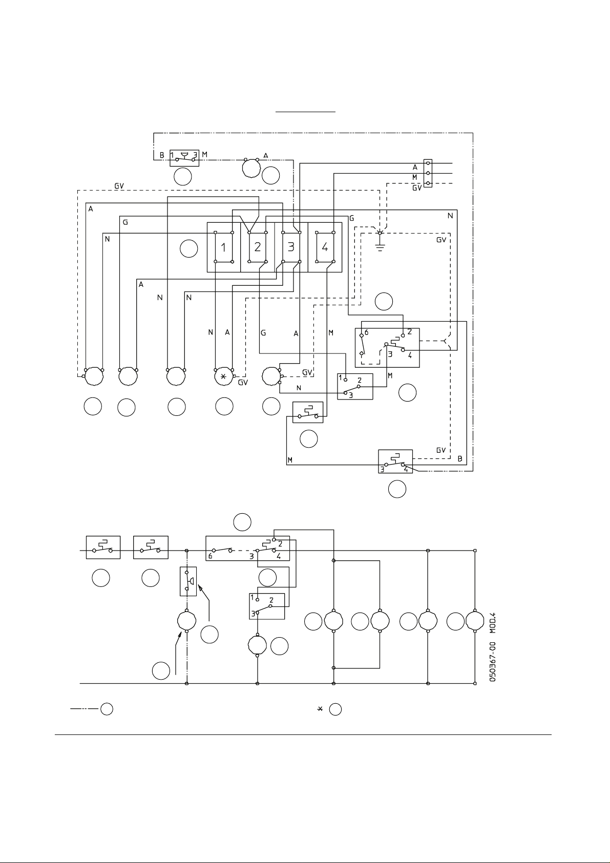
WIRING DIAGRAM - SCHEMA ELETTRICO - SCHÉMA ÉLECTRIQUE - SCHALTUNGSSCHEMA
AIR & WATER COOLED - RAFFREDDAMENTO AD ARIA ED AD ACQUA.
REFROIDISSEMENT A AIR ET A EAU - LUFT- UND WASSERGEKÜHLT
230/50-60/1
B - WHITE
BIANCO
BLANC
WEISS
N - BLACK
11
12
1
NERO
NOIR
SCHWARZ
A - BLUE
BLU
BLEU
BLAU
M - BROWN
MARRONE
MARRON
BRAUN
GV - YELLOW GREEN
GIALLO VERDE
JAUNE VERT
GELB - GRÜN
2
5
7
9 3
12
10
8
6 4
9
3
2
10
8 7 5 6
11
4
JUST FOR WATER COOLED UNIT
SOLO PER RAFF. AD ACQUA
A
SEUL POUR REFR. A EAU
NUR FÜR WASSERGEKÜHLTE EINHEIT
1 TERMINAL BOARD - MORSETTIERA
BORNIER - ANSCHLUSSKASTEN
2 EVAPORATOR THERMOSTAT - TERMOSTATO EVAPORATORE
THERMOSTAT EVAPORATEUR - VERDAMPFERTHERMOSTAT
3 BIN THERMOSTAT - TERMOSTATO CONTENITORE
THERMOSTAT CABINE - SPEICHERTHERMOSTAT
4 COMPRESSOR - COMPRESSORE
COMPRESSEUR - KOMPRESSOR
B
5 WATER PUMP - POMPA
POMPE A EAU - WASSERPUMPE
6 FAN MOTOR - VENTILATORE
MOTOVENTILATEUR - LÜFTERMOTOR
7 WATER SOL. VALVE - VALV. INGR. ACQUA
VANNE ARRIVÉE EAU - WAISSEREINLASSVENTIL
8 HOT. GAS VALVE - VALVOLA GAS CALDO
VANNE GAZ CHAUDS - HEISSGASVENTIL
JUST FOR AIR COOLED UNIT
SOLO PER RAFF. AD ARIA
SEUL POUR REFR. A AIR
NUR FÜR LUFTGEKÜHLTE EINHEIT
9 HI TEMP. THERMOSTAT - TERMOSTATO DI MASSIMA
THERMOSTAT DE SECURITÉ - SICHERHEITSTHERMOSTAT
10 FILLING SWITCH - INTERRUTTORE CARICO
INTERRUPTEUR CHARGEMENT EAU - FÜLLSCHALTER
11 PRESSURE CTRL - PRESSOSTATO
PRESSOSTAT - DRUCKSCHALTER
12 COND. WATER SOL. VALVE - VALV. ALIM. ACQUA COND.
VANNE ARR. EAU CONDEN. - WASSEREINLASSVENTIL KOND.
Page 7

d
ICEU 105
f)
WIRING DIAGRAM - SCHEMA ELETTRICO - SCHÉMA ÉLECTRIQUE - SCHALTUNGSSCHEMA
AIR & WATER COOLED - RAFFREDDAMENTO AD ARIA ED AD ACQUA.
REFROIDISSEMENT A AIR ET A EAU - LUFT- UND WASSERGEKÜHLT
230/50-60/1
A - BLUE
AZZURRO
BLEU
BLAU
TIMER
13
14
2
3
12
B - WHITE
BIANCO
BLANC
WEISS
M - BROWN
MARRONE
MARRON
BRAUN
N - BLACK
NERO
NOIR
SCHWARZ
G - GREY
GRIGIO
GRIS
GRAU
11
9
1
4
7
8
5
106 -
12
11
13
9
2
14
1
1 TERMINAL BOARD - MORSETTIERA
BORNIER - ANSCHLUSSKASTEN
2 EVAPORATOR THERMOSTAT - TERMOSTATO EVAPORATORE
THERMOSTAT EVAPORATEUR - VERDAMPFERTHERMOSTAT
3 BIN THERMOSTAT - TERMOSTATO CONTENITORE
THERMOSTAT CABINE - SPEICHERTHERMOSTAT
4 COMPRESSOR - COMPRESSORE
COMPRESSEUR - KOMPRESSOR
5 WATER PUMP - POMPA
POMPE A EAU - WASSERPUMPE
106 -
13 8
6 FAN MOTOR - VENTILATORE
MOTOVENTILATEUR - LÜFTERMOTOR
7 WATER SOL. VALVE - VALV. INGR. ACQUA
VANNE ARRIVÉE EAU - WAISSEREINLASSVENTIL
8 HOT. GAS VALVE - VALVOLA GAS CALDO
VANNE GAZ CHAUDS - HEISSGASVENTIL
9 PRESSURE CTRL - PRESSOSTATO
PRESSOSTAT - DRUCKSCHALTER
10 COND. WATER SOL. VALVE - VALV. ALIM. ACQUA COND.
VANNE ARR. EAU CONDEN. - WASSEREINLASSVENTIL KOND.
7
5
11 SWITCH - INTERRUTTORE
INTERRUPTEUR - SCHALTER
12 HI THERMOSTAT - TERMOSTATO DI SICUREZZA
THERMOSTAT DE SECURITE - SICHERHEITSTHERMOSTAT
13 TIMER - TIMER
PENDULE - ZEITHUR
14 COMPRESSOR SWITCH - INTERRUTTORE COMPRESSORE
INTERRUPTEUR COMPRESSEUR - KOMPRESSORSCHALTER
4
Page 8

d
ICEU 145 - 185
g)
WIRING DIAGRAM - SCHEMA ELETTRICO - SCHÉMA ÉLECTRIQUE - SCHALTUNGSSCHEMA
AIR & WATER COOLED - RAFFREDDAMENTO AD ARIA ED AD ACQUA.
REFROIDISSEMENT A AIR ET A EAU - LUFT- UND WASSERGEKÜHLT
230/50-60/1
A - BLUE
AZZURRO
BLEU
BLAU
TIMER
13
10
2
3
9
B - WHITE
BIANCO
BLANC
WEISS
M - BROWN
MARRONE
MARRON
BRAUN
N - BLACK
NERO
NOIR
SCHWARZ
G - GREY
GRIGIO
GRIS
GRAU
12
11
1
14
7
8
5
6
4
9
12
3
11
14
2
10
1
4
1 TERMINAL BOARD - MORSETTIERA
BORNIER - ANSCHLUSSKASTEN
2 EVAPORATOR THERMOSTAT - TERMOSTATO EVAPORATORE
THERMOSTAT EVAPORATEUR - VERDAMPFERTHERMOSTAT
3 BIN THERMOSTAT - TERMOSTATO CONTENITORE
THERMOSTAT CABINE - SPEICHERTHERMOSTAT
4 COMPRESSOR - COMPRESSORE
COMPRESSEUR - KOMPRESSOR
5 WATER PUMP - POMPA
POMPE A EAU - WASSERPUMPE
136
6 FAN MOTOR - VENTILATORE
7 WATER SOL. VALVE - VALV. INGR. ACQUA
8 HOT. GAS VALVE - VALVOLA GAS CALDO
9 HI TEMP. THERMOSTAT - TERMOSTATO DI MASSIMA
10 COMPRESSOR SWITCH - INTERRUTTORE COMPRESSORE
7
MOTOVENTILATEUR - LÜFTERMOTOR
VANNE ARRIVÉE EAU - WAISSEREINLASSVENTIL
VANNE GAZ CHAUDS - HEISSGASVENTIL
THERMOSTAT DE SECURITÉ - SICHERHEITSTHERMOSTAT
INTERRUPTEUR COMPRESSEUR - KOMPRESSORSCHALTER
8 5
11 PRESSURE CTRL - PRESSOSTATO
PRESSOSTAT - DRUCKSCHALTER
12 SWITCH - INTERRUTTORE
INTERRUPTEUR - SCHALTER
13 TIMER - TIMER
PENDULE - ZEITHUR
14 CONTACTOR - TELERUTTORE
CONTACTEUR - SCHALTSCHUTZ
Page 9

h)
Capacità di produzione - Ice making capacity - Capacité de production - Eisproduktionskapazität
RAFFREDDAMENTO AD ARIA - AIR COOLED MODELS
CONDENSATION PAR AIR - LUFTKÜHLUNG
Kg.
23
22
21
20
19
18
17
16
15
14
13
PRODUZIONE GHIACCIO PER 24 ORE - ICE PRODUCED PER 24 HRS.
TEMPÉRATURE DE L'EAU - WASSERTEMPERATUR
PRODUCTION DE GLACE PAR 24 HEURES - EISWÜRFELPRODUKTION IN 24 STD.
RAFFREDDAMENTO AD ARIA - AIR COOLED MODELS
Kg.
28
27
26
25
24
23
22
21
20
19
18
PRODUZIONE GHIACCIO PER 24 ORE - ICE PRODUCED PER 24 HRS.
17
16
PRODUCTION DE GLACE PAR 24 HEURES - EISWÜRFELPRODUKTION IN 24 STD.
15
14
TEMPÉRATURE DE L'EAU - WASSERTEMPERATUR
27 21 15
32 2732
TEMPERATURA ACQUA - WATER TEMPERATURE
CONDENSATION PAR AIR - LUFTKÜHLUNG
27 21 15 10
TEMPERATURA ACQUA - WATER TEMPERATURE
°C
10
21
32
38
10 10
°C
10
21
32
38
ICEU 045
TEMPÉRATURE AMBIANT - RAUMTEMPERATUR
TEMPERATURA AMBIENTE - AMBIENT TEMPERATURE
ICEU 065
TEMPÉRATURE AMBIANT - RAUMTEMPERATUR
TEMPERATURA AMBIENTE - AMBIENT TEMPERATURE
RAFFREDDAMENTO AD ACQUA - WATER COOLED MODELS
CONDENSATION PAR EAU - WASSERKÜHLUNG
Kg.
23
22
21
20
19
18
17
16
15
14
13
PRODUZIONE GHIACCIO PER 24 ORE - ICE PRODUCED PER 24 HRS.
PRODUCTION DE GLACE PAR 24 HEURES - EISWÜRFELPRODUKTION IN 24 STD.
PRODUZIONE GHIACCIO PER 24 ORE - ICE PRODUCED PER 24 HRS.
PRODUCTION DE GLACE PAR 24 HEURES - EISWÜRFELPRODUKTION IN 24 STD.
TEMPERATURA ACQUA - WATER TEMPERATURE
TEMPÉRATURE DE L'EAU - WASSERTEMPERATUR
RAFFREDDAMENTO AD ACQUA - WATER COOLED MODELS
CONDENSATION PAR EAU - WASSERKÜHLUNG
Kg.
28
27
26
25
24
23
22
21
20
19
18
17
16
15
14
TEMPERATURA ACQUA - WATER TEMPERATURE
TEMPÉRATURE DE L'EAU - WASSERTEMPERATUR
21 15
27 21 15 103232
°C
10
21
32
38
°C
10
21
32
38
TEMPERATURA AMBIENTE - AMBIENT TEMPERATURE
TEMPERATURA AMBIENTE - AMBIENT TEMPERATURE
TEMPÉRATURE AMBIANT - RAUMTEMPERATUR
TEMPÉRATURE AMBIANT - RAUMTEMPERATUR
RAFFREDDAMENTO AD ARIA - AIR COOLED MODELS
CONDENSATION PAR AIR - LUFTKÜHLUNG
Kg.
42
40
38
36
34
32
30
28
26
24
22
PRODUZIONE GHIACCIO PER 24 ORE - ICE PRODUCED PER 24 HRS.
TEMPÉRATURE DE L'EAU - WASSERTEMPERATUR
PRODUCTION DE GLACE PAR 24 HEURES - EISWÜRFELPRODUKTION IN 24 STD.
27 15
32
TEMPERATURA ACQUA - WATER TEMPERATURE
°C
10
21
32
38
ICEU 085
TEMPÉRATURE AMBIANT - RAUMTEMPERATUR
TEMPERATURA AMBIENTE - AMBIENT TEMPERATURE
RAFFREDDAMENTO AD ACQUA - WATER COOLED MODELS
CONDENSATION PAR EAU - WASSERKÜHLUNG
Kg.
42
40
38
36
34
32
30
28
26
24
22
32
PRODUZIONE GHIACCIO PER 24 ORE - ICE PRODUCED PER 24 HRS.
TEMPÉRATURE DE L'EAU - WASSERTEMPERATUR
PRODUCTION DE GLACE PAR 24 HEURES - EISWÜRFELPRODUKTION IN 24 STD.
27 211021
TEMPERATURA ACQUA - WATER TEMPERATURE
15 10
°C
10
21
32
38
TEMPERATURA AMBIENTE - AMBIENT TEMPERATURE
TEMPÉRATURE AMBIANT - RAUMTEMPERATUR
Page 10

i)
Capacità di produzione - Ice making capacity - Capacité de production - Eisproduktionskapazität
RAFFREDDAMENTO AD ARIA - AIR COOLED MODELS
CONDENSATION PAR AIR - LUFTKÜHLUNG
Kg.
50
48
46
44
42
40
38
36
34
32
30
32
PRODUZIONE GHIACCIO PER 24 ORE - ICE PRODUCED PER 24 HRS.
PRODUCTION DE GLACE PAR 24 HEURES - EISWÜRFELPRODUKTION IN 24 STD.
TEMPÉRATURE DE L'EAU - WASSERTEMPERATUR
RAFFREDDAMENTO AD ARIA - AIR COOLED MODELS
Kg.
75
70
65
60
55
27 21 15 10
TEMPERATURA ACQUA - WATER TEMPERATURE
CONDENSATION PAR AIR - LUFTKÜHLUNG
°C
10
21
32
38
°C
10
21
32
38
ICEU 105
TEMPÉRATURE AMBIANT - RAUMTEMPERATUR
TEMPERATURA AMBIENTE - AMBIENT TEMPERATURE
ICEU 145
RAFFREDDAMENTO AD ACQUA - WATER COOLED MODELS
CONDENSATION PAR EAU - WASSERKÜHLUNG
Kg.
50
48
46
44
42
40
38
36
34
32
30
32
PRODUZIONE GHIACCIO PER 24 ORE - ICE PRODUCED PER 24 HRS.
PRODUCTION DE GLACE PAR 24 HEURES - EISWÜRFELPRODUKTION IN 24 STD.
TEMPÉRATURE DE L'EAU - WASSERTEMPERATUR
RAFFREDDAMENTO AD ACQUA - WATER COOLED MODELS
Kg.
75
70
65
60
55
27 21 15 10
TEMPERATURA ACQUA - WATER TEMPERATURE
CONDENSATION PAR EAU - WASSERKÜHLUNG
°C
10
21
32
38
°C
10
21
32
38
TEMPERATURA AMBIENTE - AMBIENT TEMPERATURE
TEMPÉRATURE AMBIANT - RAUMTEMPERATUR
50
45
40
32
PRODUZIONE GHIACCIO PER 24 ORE - ICE PRODUCED PER 24 HRS.
PRODUCTION DE GLACE PAR 24 HEURES - EISWÜRFELPRODUKTION IN 24 STD.
TEMPÉRATURE DE L'EAU - WASSERTEMPERATUR
RAFFREDDAMENTO AD ARIA - AIR COOLED MODELS
Kg.
85
80
75
70
65
60
55
50
27 21 15 10
TEMPERATURA ACQUA - WATER TEMPERATURE
CONDENSATION PAR AIR - LUFTKÜHLUNG
32
27 21 15 10
°C
10
21
32
38
PRODUZIONE GHIACCIO PER 24 ORE - ICE PRODUCED PER 24 HRS.
TEMPERATURA ACQUA - WATER TEMPERATURE
PRODUCTION DE GLACE PAR 24 HEURES - EISWÜRFELPRODUKTION IN 24 STD.
TEMPÉRATURE DE L'EAU - WASSERTEMPERATUR
TEMPÉRATURE AMBIANT - RAUMTEMPERATUR
TEMPERATURA AMBIENTE - AMBIENT TEMPERATURE
ICEU 185
TEMPÉRATURE AMBIANT - RAUMTEMPERATUR
TEMPERATURA AMBIENTE - AMBIENT TEMPERATURE
50
45
40
32
PRODUZIONE GHIACCIO PER 24 ORE - ICE PRODUCED PER 24 HRS.
PRODUCTION DE GLACE PAR 24 HEURES - EISWÜRFELPRODUKTION IN 24 STD.
TEMPÉRATURE DE L'EAU - WASSERTEMPERATUR
RAFFREDDAMENTO AD ACQUA - WATER COOLED MODELS
Kg.
85
80
75
70
65
60
55
50
27 21 15 10
TEMPERATURA ACQUA - WATER TEMPERATURE
CONDENSATION PAR EAU - WASSERKÜHLUNG
32
27 21 15 10
°C
10
21
32
38
PRODUZIONE GHIACCIO PER 24 ORE - ICE PRODUCED PER 24 HRS.
TEMPERATURA ACQUA - WATER TEMPERATURE
PRODUCTION DE GLACE PAR 24 HEURES - EISWÜRFELPRODUKTION IN 24 STD.
TEMPÉRATURE DE L'EAU - WASSERTEMPERATUR
TEMPERATURA AMBIENTE - AMBIENT TEMPERATURE
TEMPERATURA AMBIENTE - AMBIENT TEMPERATURE
TEMPÉRATURE AMBIANT - RAUMTEMPERATUR
TEMPÉRATURE AMBIANT - RAUMTEMPERATUR
Page 11

Page 1
GENERAL INFORMATION
AND INSTALLATION
A. INTRODUCTION
These Cubers are quality designed, engineered
and manufactured.
Their ice making systems are thoroughly tested
providing the utmost in flexibility to fit the needs
of a particular user.
These ice makers have been engineered to our
own rigid safety and performence standards.
NOTE.
built into this icemaker, it is important that
installation and maintenance be conducted
in the manner outlined in this manual.
B. UNPACKING AND INSPECTION
1. Visually inspect the exterior of the packing
and skid. Any severe damage noted should be
reported to the delivering carrier and a concealed
damage claim form filled in subjet to inspection of
the contents with the carrier’s representative
present.
2. a) Cut and remove the plastic strip securing
the carton box to the skid.
the polystyre protection sheet.
corners and then remove the carton.
3. Remove the front and the rear panels of the
unit and inspect for any concealed damage.
Notify carrier of your claim for the concealed
damage as stated in step 1 above.
4. Open the bin door and remove all internal
support packing and masking tape.
To retain the safety and performance
b) Cut open the top of the carton and remove
c) Pull out the polystyre posts from the
7. See data plate on the rear side of the unit
and check that local main voltage corresponds
with the voltage specified on it.
CAUTION. Incorrect voltage supplied to
the icemaker will void your parts
replacement program.
8. Remove the manufacturer’s registration
card from the inside of the User Manual and fillin all parts including: Model and Serial Number
taken from the data plate.
Forward the completed self-addressed
registration card to the factory.
C. LOCATION AND LEVELLING
WARNING. This Ice Cuber is designed for
indoor installation only. Extended periods
of operation at temperatures exceeding
the following limitations will constitute
misuse under the terms of the
Manufacturer’s Limited Warranty
resulting in LOSS of warranty coverage.
1. Position the unit in the selected permanent
location.
Criteria for selection of location include:
a) Minimum room temperature 10°C (50°F)
and maximum room temperature 40°C (100°F).
b) Water inlet temperatures: minimum 5°C
(40°F) and maximum 35°C (90°F).
c) Well ventilated location for air cooled
models. Clean the air cooled condenser at
frequent intervals.
d) Service access: adequate space must
be left for all service connections through the rear
of the ice maker. A minimum clearance of 15 cm
(6") must be left at the sides of the unit for routing
cooling air drawn into and exhausted out of the
compartment to maintain proper condensing
operation of air cooled models.
5. Check that refrigerant lines do not rub
against or touch other lines or surfaces, and that
the fan blade moves freely.
6. Use clean damp cloth to wipe the surfaces
inside the storage bin and the outside of the
cabinet.
NOTE.
With the unit in “built-in” conditions,
the ice production is gradually reduced in
respect to the levels shown in the graph, up
to a maximum of 10% at room temperatures
higher than 32°C.
The daily ice-making capacity is directly
related to the condenser air inlet temperature, water temperature and age of the machine.
To keep your CUBER at peak performance
levels, periodic maintenance checks must
be carried out as indicated on Cleaning
Section of this manual.
2. Level the unit in both the left to right and
front to rear directions.
Page 12

Page 2
D. ELECTRICAL CONNECTIONS
See data plate for current requirements to
determine wire size to be used on electrical
connections. All icemakers require a solid earth
wire.
The ice machines are supplied from the factory
completely pre-wired and require only electrical
power connections to wire cord provided on the
back of the unit.
Make sure that the ice machine is connected to
its own circuit and individually fused (see data
plate for fuse size).
The maximum allowable voltage variation should
not exceed -10% and +10% of the data plate
rating. Low voltage can cause faulty functioning
and may be responsible for serious damage to
the overload switch and motor windings.
NOTE.
All external wiring should conform to
national, state and local standards and
regulations.
Check voltage on the line and the ice maker’s
data plate before connecting the unit.
E. WATER SUPPLY AND DRAIN
CONNECTIONS
General
When choosing the water supply for the ice cuber
consideration should be given to:
a) Length of run
b) Water clarity and purity
c) Adequate water supply pressure
Since water is the most important single ingredient
in producting ice you cannot emphasize too
much the three items listed above.
Low water pressure, below 1 bar may cause
malfunction of the ice maker unit.
Water containing excessive minerals will tend to
produce cloudy coloured ice cubes, plus scale
built-up on parts of the water system.
fitting and a shut-off valve installed in an
accessible position between the water supply
line and the unit.
Water supply - Water cooled models
(ICEU 145, 185 only)
The water cooled versions of series 65 and 90
require two separate inlet water supplies, one for
the water sprayed for making the ice cubes and
the other for the water cooled condenser.
Connect the 3/4" male fitting of the water
regulating valve using the flexible hose supplied
with the unit to the cold water supply line with
regular plumbing fitting and a shut-off valve
installed in an accessible position between the
water supply line and the unit.
Water drain
The recommended drain tube is a plastic or
flexible tube with 18 mm (3/4") I.D. runs to an
open trapped and vented drain. When the drain
is a long run, allow 3 cm pitch per meter (1/4"
pitch per foot).
A vertical open vent, at the unit drain connection,
is also required for proper sump drainage.
Water drain - Water cooled models
The water drain line from the condenser, on
water cooled versions, is internally connected
with the drain fitting of the unit.
It is strongly recommended therefore to install a
vertical open vent on unit drain line high point to
ensure good draining and to direct the drain line
to a trapped and vented floor drain receptacle.
This to make sure of the proper flow of the
drained water as, in case of poor drainage, the
water ranning out from the condenser may
inopportunely flow, through the unit drain tubing,
into the ice storage bin.
Water supply
Connect the 3/4" male fitting of the solenoid
water inlet valve, using the flexible hose supplied,
to the cold water supply line with regular plumbing
NOTE.
The water supply and the water drain
must be installed to conform with the local
code. In some case a licensed plumber and/
or a plumbing permit is required.
Page 13

Page 3
F. FINAL CHECK LIST
1. Is the unit in a room where ambient
temperatures are within a minimum of 10°C
(50°F) even in winter months?
2. Is there at least a 15 cm (6") clearance
around the unit for proper air circulation?
3. Is the unit level? (IMPORTANT)
4. Have all the electrical and plumbing
connections been made, and is the water supply
shut-off valve open?
5. Has the voltage been tested and checked
against the data plate rating?
6. Has the water supply pressure been
checked to ensure a water pressure of at least
G. INSTALLATION PRACTICE
1 bar (14 psi).
7. Check all refrigerant lines and conduit lines
to guard against vibrations and possible failure.
8. Have the bin liner and cabinet been wiped
clean?
9. Has the owner/user been given the User
Manual and been instructed on the importance of
periodic maintenance checks?
10. Has the Manufacturer’s registration card
been filled in properly? Check for correct model
and serial number against the serial plate and
mail the registration card to the factory.
11. Has the owner been given the name and the
phone number of the authorized Service Agency
serving him?
1. Hand shut-off valve
2. Water filter
3. Water supply line (flexible hose)
4. 3/4" male fitting
5. Vented drain
6. Open trapped vented drain
7. Drain fitting
8. Main switch
9. Power line
WARNING. This icemaker is not designed for outdoor installation and will not function in
ambient temperatures below 10°C (50°F) or above 40°C (100°F).
This icemaker will malfunction with water temperatures below 5°C (40°F) or above 35°C
(90°F).
Page 14

Page 4
OPERATING INSTRUCTIONS
START UP
After having correctly installed the ice maker and
completed the plumbing and electrical
connections, perform the following “Start-up” procedure.
ICEU 045 - 065 - 085
A. Remove the unit front panel and locate the
cleaning switch on the control box.
B. Set the cleaning switch in the cleaning
position (II). This will close the electrical circuit to
the water inlet valve and to the hot gas valve.
C. Switch ON the power line disconnect
switch. Unit will start up in water filling phase
mode.
During this phase the components energized
are:
WATER INLET SOLENOID VALVE
HOT GAS SOLENOID VALVE
The Water pump and the Fan motor are also in
operation.
D. Set the master switch to the ON position.
The compressor switch must stay in the OFF
position. This will close the electrical circuit to the
water inlet valve and to the hot gas valve.
E. Switch ON the power line disconnect
switch. Unit will start up in defrost cycle mode.
During this cycle the components energized are:
WATER INLET SOLENOID VALVE
HOT GAS SOLENOID VALVE
TIMER MOTOR
F. After completion of harvest cycle (about
three minutes) move the compressor switch to
ON position.
NOTE.
During the defrost cycle, the water
inlet solenoid valve is energized. The water
flows through the valve to the back side of the
evaporator platen and then down to fill up the
icemaker sump tank for the next freezing
cycle.
D. Let unit stay in water filling phase mode for
about three/four minutes till water is coming out
from the drain hose, then move the cleaning
switch to the operation position (I).
ICEU 105 - 145 - 185
A. Remove the unit front panel and locate the
timer shaft on the control box.
B. Check that master and the compressor
switch located on the lower left hand side of the
control box are both in the OFF position.
C. Rotate the timer shaft protruding through
the front of the control box clockwise, until and
audible click is heard indicating that the actuator
arm of the microswitch has dropped into the cam
slot (Fig. A).
OPERATIONAL CHECKS
A. The unit now starts its first freezing cycle
with the following components in operation:
COMPRESSOR
WATER PUMP
FAN MOTOR in air cooled version
B. Check to see through the ice discharge
opening that the spray system is correctly seated
and that the water jets uniformely reach the
interior of the inverted cup molds; also make sure
that the plastic curtain is hanging freely and there
is not excessive water spilling through it.
C. The ice making process takes place
thereby, with the water sprayed into the molds
that gets gradually refrigerated by the heat
exchanged with the refrigerant flowing into the
evaporator serpentine.
D. On units ICEU 045 - 065 - 085 when the
evaporator temperature reaches a preset value
the evaporator thermostat or cube size control
changes its contacts; the freezing cycle ends and
starts the defrost or harvest cycle.
E.
On units ICEU 105 - 145 - 185 the time clock
does not rotate at the end of the harvest cycle. It
starts later when the cube size thermostat control
bulb (pig tail) located on the evaporator coil
reaches a temperature of approx. -15°C (5°F).
Page 15

Page 5
Freezing time will range between 20 and 22
minutes in a 21°C ambient temperature, longer if
above this temperature and shorter if below. The
average complete cycle time is between 23 and
25 minutes.
F. Check, during the first defrost/harvest
cycle, that the incoming water flows correctly into
the sump reservoir in order to re-fill it and the
surplus overflows through the overflow drain tube.
G. Check the texture of ice cubes just
released. Right size must have a small depression
(about 5-6 mm) in their crown.
If not, wait for the second defrost/harvest cycle
before performing any adjustment.
H. If required on model ICEU 045, 065 and
085, the length of the freezing cycle can be
modified by turning the knob of the cube size
control or evaporator thermostat located in front
of the control box until the desired size is achieved.
• If the temperature of the room in
which the machine
is place is below
20°C, the cubes will
tend to be partly
hollowed out (see
fig. on right).
• If, on the other
hand, the room
temperature is
above 30°C the
cubes produced
will have a jagged
rim of ice around
the crown.
It should, however, be remembered that if the
room temperature returns later to the 20 ÷ 30°C
range, the knob indicator must once again be
turned to point to the dot (see fig. below).
If the ice cubes are shallow and cloudy, it is
possible that the ice maker runs short of water
during the end of the freezing cycle or, the quality
of the supplied water requires the use of an
appropriate water filter or conditioner.
I. At the end of the defrost or harvest cycle
hold a handful of ice cubes against the bulb of the
storage bin thermostat; the icemaker switch OFF
in about one-two minutes.
Take out the ice from the storage bin thermostat.
The ice maker should restart automatically in
three-four minutes.
NOTE.
The bin thermostat is factory set at
1°C (35°F) OUT and 4°C (39°F) IN.
If it is thought necessary, the above situations
can be rectified by, in the first case, turning the
control knob (as little or as much as is required)
clockwise and, in the second case, turning the
knob to the right counterclockwise.
K. Re-fit the unit front panel then instruct the
owner/user on the general operation of the ice
machine and about the cleaning and care it
requires.
Page 16

Page 6
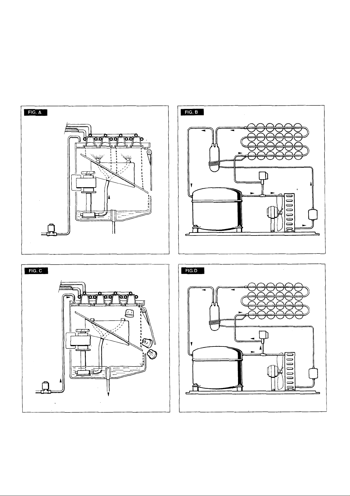
PRINCIPLE OF OPERATION
How it works
In the ice makers the water used to make the ice
is kept constantly in circulation by a water pump
which primes it to the spray system nozzles from
where it is diverted into the inverted cup molds of
the evaporator (Fig. A).
A small quantity of the sprayed water freezes into
ice; the rest of it cascades by gravity into the
sump assembly below for recirculation.
FREEZING CYCLE (Fig. B)
The hot gas refrigerant discharged out from the
compressor reaches the condenser where, being
cooled down, condenses into liquid. Flowing into
the liquid line it passes through the drier/filter,
then it goes all the way through the capillary tube
where it looses its pressure.
Next the refrigerant enters into the evaporator
serpentine (which has a larger diameter then the
capillary tube) and starts to boil off; this reaction
is emphasized by the heat transferred by the
sprayed water.
The refrigerant then increases in volume and
changes entirely into vapor.
The vapor refrigerant then passes through the
suction accumulator (used to prevent that any
small amount of liquid refrigerant may reach the
compressor) and through the suction line. In both
the accumulator and the suction line it exchanges
heat with the refrigerant flowing into the capillary
tube (warmer), before to be sucked in the
compressor and to be recirculated as hot
compressed refrigerant gas.
The freezing cycle on ICEU 045 - 065 - 085 is
controlled by only the evaporator thermostat
which has its bulb in contact with the evaporator
serpentine while in ICEU 105 - 145 - 185 there is
an second phase controlled by a timer.
The electrical components in operation during
the freezing cycle are:
COMPRESSOR
WATER PUMP
FAN MOTOR (in air cooled version)
On ICEU 045 - 065 - 085 air cooled versions the
refrigerant head pressure is gradually reduced
from a value of approx. 11 bars (155 psig) at the
beginning of the freezing cycle with the unit at
21°C (70°F) ambient temperature, to a minimun
value of approx. 7 bars (100 psig) just at the end
of the freezing cycle few seconds before the
starting of the defrost cycle.
On ICEU 105 - 145 - 185 air cooled versions the
refrigerant head pressure is kept between two
pre-set values (10÷8,5 bar - 140÷ 120 psig) with
the unit a 21°C (70°F) ambient temperature.
The declining of the pressure is relied to the
reduction of the evaporating pressure, caused
by the progressive growth of the ice thickness
into the inverted cup molds and to the flow of air
drown through the air cooled condenser by the
fan motor. The above values are in relation as
well to the ambient temperature of the ice maker
site and they are subject to rise with the increase
of this temperature.
On ICEU 045 - 065 - 085 - 105 water cooled
versions the refrigerant head pressure ranges
between 8.5 and 10 bars (120÷ 140 psig) being
controlled by an automatic hi pressure control
that energizes a water solenoid valve located on
the water line to the condenser, which rates the
cooling water to the condenser.
On ICEU 145 - 185 water cooled versions the
head pressure is constant at 9.5 bar (135 psig)
controlled by a water regulating valve.
At starting of freezing cycle the refrigerant suction
or lo-pressure lowers rapidly to 1.0 bar - 14 psig
then it declines gradually - in relation with the
growing of the ice thickness - to reach, at the end
of the cycle, approx. 0÷0.1 bar - 0÷1.5 psig on
the models 045, 065 and 0.85 and 0.2÷0.3 bar
(3÷4 psig) on models 105 - 145 and 185 with the
cubes fully formed in the cup molds.
The total length of the freezing cycle ranges from
23 to 25 minutes.
DEFROST OR HARVEST CYCLE (Fig. D)
On ICEU 045 - 065 - 085 the temperature of the
evaporator thermostat, in contact with the
evaporator serpentine, drops to a pre-set value it
changes its electrical contacts energizing the
herebelow shown components.
(On ICEU 105 - 145 - 185 when the timer microswitch
drops down into the lower portion of the cam it
changes its electrical contacts energizing the
same components).
COMPRESSOR
WATER INLET SOLENOID VALVE
HOT GAS SOLENOID VALVE
The incoming water, passing through the water
inlet valve and the flow control, runs over the
evaporator platen and then flows by gravity
through the dribbler holes down into the sump/
reservoir (Fig. C).
The water filling the sump/reservoir forces part of
the surplus water from the previous freezing
cycle to go out to the waste through the overflow
pipe. This overflow limits the level of the sump
water which will be used to produce the next
batch of ice cubes.
Meanwhile the refrigerant, as hot gas discharged
from the compressor, flows through the hot gas
valve directly into the evaporator serpentine bypassing the condenser.
The hot gas circulating into the serpentine of the
evaporator warms up the copper molds causing
the harvest of the ice cubes. The ice cubes,
released from the cups, drop by gravity onto a
slanted cube chute, then through a curtained
opening they fall into the storage bin.
Page 17

Page 7
On ICEU 045 - 065 - 085 when the temperature
of the evaporator thermostat bulb reaches the
value of +3÷4°C their electrical contacts move
back to the previous position activating a new
freezing cycle and deenergizing both the hot gas
and the water inlet valves (closed).
On ICEU 105 - 145 - 185 as soon as the timer
microswitch completes the bottom part of the
cam and it is pushed again, it activates a new
freezing cycle deenergizing both the hot gas and
the water inlet valves (closed).
NOTE. On models 045, 065 and 085 the
length of the defrost/harvest cycle (not
adjustable) changes according to the
ambient temperature (shorter for hi ambient
temperature and longer for low one).
COMPONENTS DESCRIPTION
A. WATER PUMP
The water pump operates continually throughout
the freezing cycle. The pump primes the water
from the sump to the spray system and through
the spray nozzles sprays it into the inverted cup
molds to be frozen into crystal clear ice cubes.
B. WATER INLET SOLENOID VALVE -
3/4 MALE FITTING
The water inlet solenoid valve is energized only
during the defrost cycle.
When energized it allows a metered amount of
incoming water to flow over the evaporator cavity
to assist the hot gas in defrosting the ice cubes.
The water running over the evaporator cavity
drops by gravity, through the dribbler holes of the
platen, into the sump reservoir.
On 045 - 065 - 085 - 105 water cooled versions
the water inlet solenoid valve has one inlet and
two outlets with two separate solenoids energized
the first (ice productioon) by the contacts 3-2 of
the evaporator thermostat and the second (water
cooled condenser) by a specific hi pressure
control.
C. HOT GAS SOLENOID VALVE
The hot gas solenoid valve consists basically in
two parts: the valve body and the valve coil.
During the defrost cycle the hot gas valve coil is
activated so to attract the hot gas valve piston in
order to give way to the hot gas discharged from
compressor to flow directly into the evaporator
serpentine to defrost the formed ice cubes.
D. BIN THERMOSTAT
The bin thermostat control body is located in the
front of control box behind the front panel.
The thermostat sensing tube is located into a
bulb holder on the side wall of the ice storage bin
where it automatically shuts the icemaker OFF
when in contact with the ice and re-starts the
icemaker when the ice is removed. Factory
settings are 1°C (35°F) OUT and 4°C (39°F) IN.
E. CUBE SIZE CONTROL (EVAPORATOR
THERMOSTAT)
ICEU 045 - 065 - 085
The cube size control (evaporator thermostat)
body is located in the control box behind the front
panel; it’s basically a reverse acting temperature
control which closes the contacts 3-2 when its
temperature decreases and closes the opposite
contacts 3-4 when the temperature rises.
The thermostat sensing bulb is located into a
plastic tube (bulb holder) secured by two clips
directly to the evaporator serpentine.
This control determines the length of the freezing
cycle and correspondingly the size of the cubes.
A lower setting will produce a larger cube
(oversize) while a higher setting a smaller cuber
(shallow size).
When closed on contacts 3-2 it activates the
defrost or harvest cycle components.
The cube size control is set up in the factory
(knob in the black dot position) and doesn't
require any adjustment when the ambient
temperature remains between 20 and 30°C
(70 and 90°F).
ICEU 105 - 145 - 185
The evaporator thermostat with its sensing bulb
intimately in contact with the regrigerant outlet
tube from the evaporator senses the evaporating
refrigerant temperature (which declines in the
course of the freezing cycle) and when this one
reaches the pre-set value, it switches its contacts
from 3-4 to 3-2 to activate the finishing cycle (2nd
phase) which has a pre-set extension determined
by the large diameter lobe of the timer cam.
F. FAN MOTOR (Air cooled version)
The fan motor on 045 - 065 - 085 is electrically
connected in parallel to the water pump and it
operates continuously only during the freezing
cycle keeping the proper head pressure by
circulating air through the condenser fins.
On 105 - 145 - 185 the operation of fan motor is
controlled by a fan pressure control adjusted at
preset values.
G. COMPRESSOR
The hermetic compressor is the heart of the
refrigerant system and it is used to circulate and
retrieve the refrigerant throughout the entire
system. It compresses the low pressure
refrigerant vapor causing its temperature to rise
and become high pressure hot vapor (hot gas)
which is then released through the discharge
valve.
H. WATER SPRAY SYSTEM
Through its nozzles it sprays the water in each
individual cup to be frozen into ice.
I.
SAFETY HI TEMPERATURE THERMOSTAT
Located in the control box it is a manual reset
switch that trips OFF the operation of the machine
when its bulb (located on the liquid line just
before the drier) reaches the temperature of
70°C (158°F).
Page 18

Page 8
J. CLEANING SWITCH (only 045 - 065 - 085)
Located on the bottom left side of the control box
is used to energize the water inlet and the hot gas
valves so to charge the water into the sump tank
of the machine.
K. HI PRESSURE CONTROL (Water cooled
version)
Used only on 045 - 065 - 085 - 105 water cooled
versions it operates to keep between 8.5 and 10
bars (120 ÷ 140 psig) the hi-side or discharge
pressure of the refrigerant system by energizing
the coil of the water inlet solenoid valve that
control the cooling water flow to the condenser.
L. TIMER (only 105 - 145 - 185)
Equipped with two microswitches which plungers
ride one timer cam, the timer is located inside the
control box.
The function of the timer begins when activated
by the cube size control (evap. thermostat).
The large diameter lobe of its cam determines
the length of the 2nd portion of the freezing cycle,
while the cam small diameter lobe, determines
the time cycle for the harvest sequence.
The timer cam can be adjusted to vary the defrost
time as required.
WARNING. Never set the defrost time for
longer than 4 minutes as this will
jeopardize the compressor motor
windings.
Consequently any variation made at the timer
cam setting requires a compensation adjustment,
very fine and very accurate, of the evaporator
thermostat.
M. MASTER SWITCH (only 105 - 145 - 185)
Fitted in the control box the master switch has to
be used to start-up and to stop the ice maker
operation.
N.
COMPRESSOR SWITCH (only 105 - 145 - 185)
Located in the control box is used to de-energized
the compressor during the cleaning.
O. FAN PRESSURE CONTROL
(only 105 - 145 - 185)
Used on air cooled ice makers to maintain the
head pressure within the preset values.
P. WATER REGULATING VALVE
(only 145 - 185 Water cooled version only)
This valve controls the head pressure in the
refrigerant system by regulating the flow of water
going to the condenser.
As pressure increases, the water regulating valve opens to increase the flow of cooling water.
It goes without saying that an extension of the
defrost period will directly reduce the timed portion
of the freezing cycle and viceversa.
Q. CONTACTOR (145 - 185 only)
It operates in order to close or open the electrical
circuit to the compressor.
Page 19

MAINTENANCE AND CLEANING INSTRUCTIONS
Page 9
CLEANING INSTRUCTIONS OF WATER
SYSTEM
1. Remove the front and top panels to gain
access either to the control box and to the
evaporator.
2. Make sure that all ice cubes have been
released from their cups, then switch OFF the
machine at main power switch, on models 045 065 - 085, and on compressor and master
switches on models 105 - 145 - 185.
3. Scoop out all the ice cubes stored into the
bin in order to prevent them from being
contaminated with the cleaning solution.
4. On ICEU 045 - 065 remove the plastic cup
located on the bottom of sump/freezing chamber
to drain out all water and scale deposits.
5. Remove the curtain then, using a bottle,
poor fresh water into the bottom of the sump/
freezing chamber to clean out any possible scale
deposit.
6. Install again the curtain as well as the
bottom plastic cup.
Allow the ice maker to operate for about 20
minutes. Then turn the cleaning toggle switch to
the "cleaning" position (II) till the release of the
ice cubes from their cups.
NOTE.
The amount Cleaner and the time
needed for the cleaning of water system
depends of the water conditions.
2. Turn the cube size control knob
counterclockwise to the OFF position to shut-off
the ice maker then flush out the cleaning solution
from the sump reservoir then pour onto the
evaporator cavity two or three liters of clean
potable water to rinse the mold cups and the
platen.
3. If necessary remove the water spray platen
to clean it separately.
b
7. On all other models, flush out the water from
the sump reservoir by removing the overflow
stand pipe.
8. Prepare the cleaning solution by diluting in
a plastic container one or two liters of warm water
(45°-50°C) with a 0,1-0,2 liters of Ice Machine
Cleaner (on 045 - 065 - 085) and 0,2-0,3 liters on
105 - 145 - 185.
WARNING. The Ice Machine Cleaner
contains Phosphoric and Hydroxyacetic
acids.
These compounds are corrosive and may
cause burns if swallowed, DO NOT induce vomiting. Give large amounts of water
or milk. Call Physician immediately.
In case of external contact flush with
water. KEEP OUT OF THE REACH OF
CHILDREN.
9. Remove the evaporator cover then slowly
pour onto the evaporator platen the cleaning
solution. With the help of a brush dissolve the
most resistant and remote scale deposits in the
platen.
045 - 065 - 085
1. On 045 - 065 - 085 switch ON again the
machine at main power switch to start the
icemaking process.
4. Turn again the cube size control knob to the
normal operating position (black dot). The water
pump is again in operation to circulate the water
in order to rinse the entire water system.
Do the operation as per steps 8 and 9 twice so to
be sure no more traces of descaling solution
remains into the sump.
Pour on the upper side of the evaporator platen
fresh water with a capfull of disinfectant solution
then turn again the machine in normal operating
mode so to sanitize all the water system for
approx. 10 minutes.
NOTE.
Do not mix descaling with disinfectant
solution to avoid the generation of a very
aggressive acid.
5. Flush out the disinfectant solution from the
sump reservoir then with the switch in "cleaning"
position, turn the cube size control knob to the
normal operating position.
When water starts overflowing through the
drain line, set the switch to "operation" position.
The unit is now ready to resume normal
operation.
Page 20

Page 10
105 - 145 - 185
1. On 105 - 145 - 185 slowly rotate the clock
knob clockwise with the aid of a screwdriver until
the microswitch actuator arm is at the start position
of the freezing cycle.
Immediately set the master switch to the ON
position. Leave the compressor switch in the
OFF position.
2. Allow the system to operate for about 20
minutes into the freezing cycle. No ice will be
produced because the compressor is not in
operation.
8. Pour on the upper side of the evaporator
platen fresh water with a capfull of disinfectant
solution then put again the master switch in ON
position so to sanitize all the water system for
approx. 10 minutes.
NOTE.
Do not mix descaling with
disinfectant solution to avoid the generation
of a very aggressive acid.
9. Flush out the disinfectant solution from
the sump reservoir.
Slowly rotate the time clock knob clockwise
until the microswitch actuator arm is in the
START position of the harvest cycle and then
set the master switch to the ON position. Let
the unit run normally through this part of the
cycle. When the defrost has been completed
rotate the time clock knob manually until the
defrost cycle starts again. Do this two times.
Once the water reservoir is properly filled up,
set the compressor switch to the ON position.
The unit is now ready to resume the normal
operation.
10. Place again the evaporator cover and the
unit service panels.
11. Place again the evaporator cover and the
unit service panels.
3. At the end of this period set the master
switch to the OFF position to shut off the icemaker.
4. Remove the overflow drain tube from its
seat to drain out all the cleaning solution and
most of the mineral concentration through the
drain tube and then replace it in its seat.
5. Pour onto the evaporator cavity two or three
liters of clean potable water to rinse the mold
cups and the platen.
6. If necessary remove the water spray platen
to clean it separately.
7. Set again the master switch in ON position.
The water pump is again in operation to circulate
the water in order to rinse the entire water
system.
12. At completion of the freezing and harvest
cycle make sure of proper texture and clearness
of the ice cubes and that, they do not have any
acid taste.
ATTENTION. In case the ice cubes are
cloudy-white and have an acid taste, melt
them immediately by pouring on them
some warm water. This to prevent that
somebody could use them.
13. Wipe clean and rinse the inner surfaces of
the storage bin.
REMEMBER.
To prevent the accumulation
of undesirable bacteria it is necessary to
sanitize the interior of the storage bin with an
anti-algae disinfectant solution every week.
 Loading...