

Ice-O-Matic ICEF 155 Service Manual

Page 1
Page 1
SERVICE MANUAL
ICE UNDERCOUNTER SERIES CUBER
MODEL
ICEF 155
Rev. 07/2014

Page 2
Page 2
TABLE OF
CONTENTS
2
3
Table of contents page
Specifications
GENERAL INFORMATION AND INSTALLATION
Introduction
Unpacking and Inspection
Location and levelling
Electrical connections
Water supply and drain connections
Final check list
Installation practice
OPERATING INSTRUCTIONS
Start up
Operational checks
PRINCIPLE OF OPERATION (How it works)
Water circuit
Refrigerant circuit
Mechanical system
Operating pressures
Components description
Wiring diagram
Service diagnosis
MAINTENANCE AND CLEANING INSTRUCTIONS
General
Icemaker
Cleaning instructions of water system
13
13
15
16
17
5
5
5
5
6
6
7
8
10
25
27
29
29
29
Page 3
Page 3
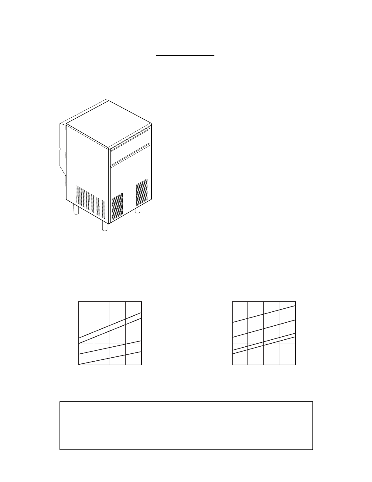
SPECIFICATIONS
ice making capacity
ELECTRONIC FLAKER MODEL ICEF 155
NOTE. With the unit in “built-in” conditions, the ice production is gradually reduced in respect to the
levels shown in the graph, up to a maximum of 10% at room temperatures higher than 32°C.
The daily ice-making capacity is directly related to the condenser air inlet temperature, water
temperature and age of the machine.
To keep your FLAKER at peak performance levels, periodic maintenance checks must be carried
out as indicated on page 29 of this manual.
Important operating requirements:
MIN MAX
- Air temperature 10°C (50°F) 40°C (100°F)
- Water temperature 5°C (40°F) 40°C (100°F)
- Water pressure 1 bar (14 psi) 5 bars (70 psi)
- Electr. voltage
variations fromvoltage
rating specified
on nameplate -10% +10%
32
38
10
21
75
70
65
60
55
50
45
Kg.
32
°C21 15
°C
o
o
AIR COOLED MODELS
WA TER TEMPERATURE
AMBIENT TEMPERATURE
ICE PRODUCED PER 24 HRS.
32
38
10
21
75
70
65
60
55
50
45
Kg.
32
°C21 15
°C
o
o
WATER COOLED MODELS
WA TER TEMPERATURE
AMBIENT TEMPERATURE
ICE PRODUCED PER 24 HRS.
Page 4
Page 4
Start Electric power cons.
Amps Kwh per 24 HR
Basic electr. Amps Watts Nr. of wires Amps fuse
SPECIFICATIONS
Model Cond. unit Finish Comp. HP
Ice bin
cap
Water req.
lt/24 HR
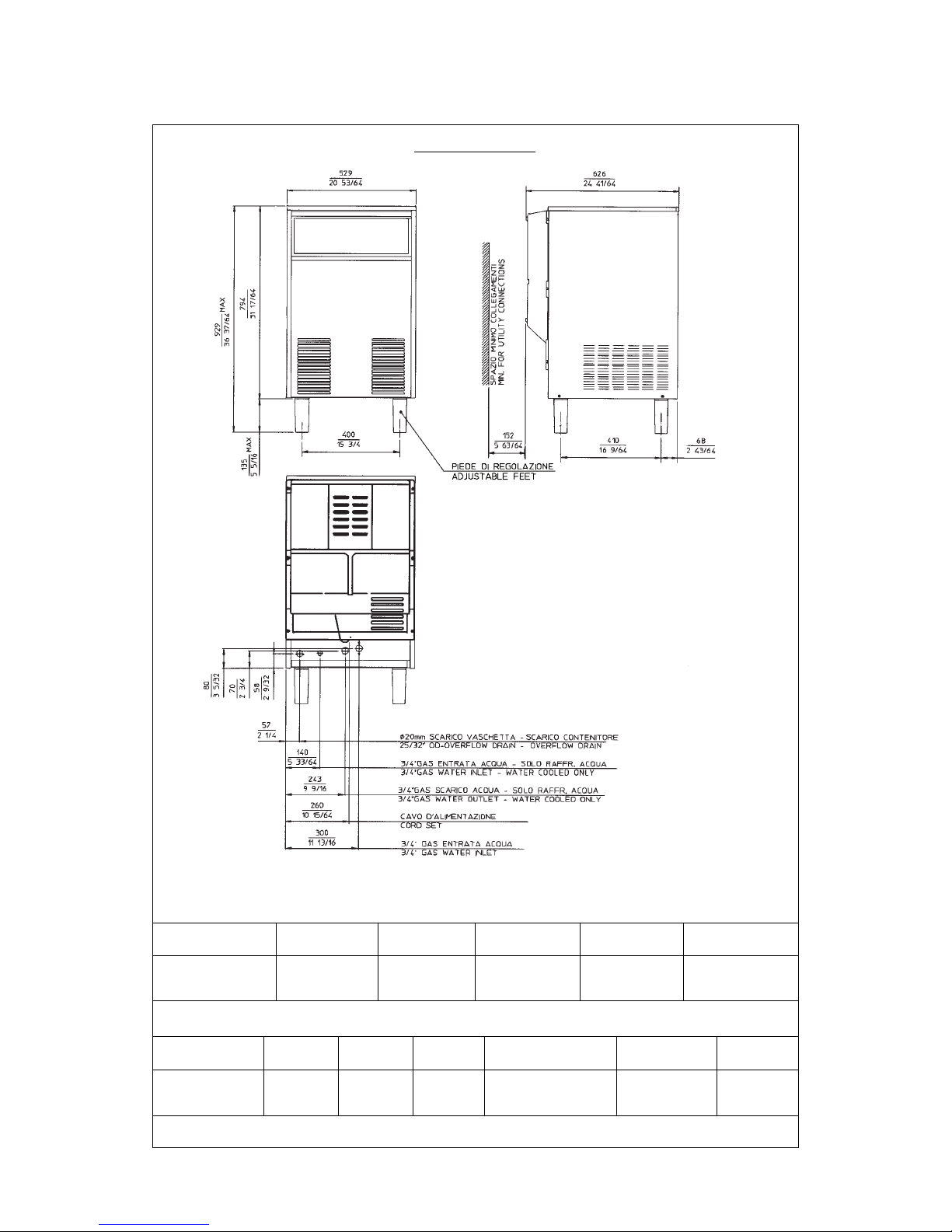
ICEF 155 - MACHINE SPECIFICATIONS
Dimensions:
HEIGHT (less legs) 794 mm.
HEIGHT (with legs) 929 mm.
WIDTH 529 mm.
DEPTH 621 mm.
WEIGHT 51 Kg.
230/50/1 2.2 11 330 7.5 3 x 1.5 mm
2
10
S. Steel 1/4 25 Kg.
ICEF 155 AS Air 53**
ICEF 155 WS Water 300*
* A 15°C water temperature

Page 5
Page 5
GENERAL INFORMATION AND INSTALLATION
A. INTRODUCTION
This manual provides the specifications and the
step-by-step procedures for the installation, startup and operation, maintenance and cleaning for
the ICEF 155 icemakers.
This Electronic Flaker is quality designed,
engineered and manufactured.
Their ice making systems are thoroughly tested
providing the utmost in flexibility to fit the needs
of a particular user.
NOTE. To retain the safety and performance
built into this icemaker, it is important that
installation and maintenance be conducted
in the manner outlined in this manual.
B. UNPACKING AND INSPECTION
1. Call the authorized Distributor or Dealer for
proper installation.
2. Visually inspect the exterior of the packing
and skid. Any severe damage noted should be
reported to the delivering carrier and a concealed
damage claim form filled in subjet to inspection of
the contents with the carrier’s representative
present.
3. a) Cut and remove the plastic strip securing
the carton box to the skid.
b) Cut open the top of the carton and remove
the polystyre protection sheet.
c) Pull out the polystyre posts from the
corners and then remove the carton.
4. Remove the front and the rear panels of the
unit and inspect for any concealed damage.
Notify carrier of your claim for the concealed
damage as stated in step 2 above.
5. Remove all internal support packing and
masking tape. (Leg package and water inlet and
outlet hoses are located in the storage bin
compartment).
6. Check that refrigerant lines do not rub against
or touch other lines or surfaces, and that the fan
blades move freely.
7. Check that the compressor fits snugly onto
all its mounting pads.
8. Use clean damp cloth to wipe the surfaces
inside the storage bin and the outside of the
cabinet.
9. See data plate on the rear side of the unit
and check that local main voltage corresponds
with the voltage specified on it.
CAUTION. Incorrect voltage supplied to
the icemaker will void your parts
replacement program.
10. Remove the manufacturer’s registration card
from the inside of the User Manual and fill-in all
parts including: Model and Serial Number taken
from the data plate.
Forward the completed self-addressed
registration card to the manufacturer.
11. If necessary fit the four legs into their seats
on the machine base and adjust them to the
desired level.
C. LOCATION AND LEVELLING
WARNING. This Ice Flaker is designed for
indoor installation only. Extended periods
of operation at temperature exceeding
the following limitations will constitute
misuse under the terms of the
Manufacturer’s Limited Warranty
resulting in LOSS of warranty coverage.
1. Position the unit in the selected permanent
location.
Criteria for selection of location include:
a) Minimum room temperature 10°C (50°F)
and maximum room temperature 40°C (100°F).
b) Water inlet temperatures: minimum 5°C
(40°F) and maximum 35°C (90°F).
c) Well ventilated location for air cooled models
(Clean the air cooled condenser at frequent
intervals).
d) Service access: adequate space must be
left for all service connections through the rear of
the ice maker. A minimum clearance of 15 cm
(6") must be left at the sides of the unit for routing
cooling air drawn into and exhausted out of the
compartment to maintain proper condensing
operation of air cooled models.
2. Level the unit in both the left to right and front
to rear directions.
D. ELECTRICAL CONNECTIONS
See data plate for current requirements to
determine wire size to be used for electrical
connections. All icemakers require a solid earth
wire.

Page 6
Page 6
All ice machines are supplied from the factory
completely pre-wired and require only electrical
power connections to the wire cord provided at
the rear of the unit.
Make sure that the ice machine is connected to
its own circuit and individually fused (see data
plate for fuse size).
The maximum allowable voltage variation should
not exceed -10% and +10% of the data plate
rating. Low voltage can cause faulty functioning
and may be responsible for serious damage to
the overload switch and motor windings.
NOTE. All external wiring should conform to
national, state and local standards and
regulations.
Check voltage on the line and the ice maker’s
data plate before connecting the unit.
E. WATER SUPPLY AND DRAIN
CONNECTIONS
GENERAL
When choosing the water supply for the ice flaker
consideration should be given to:
a) Length of run
b) Water clarity and purity
c) Adequate water supply pressure
Since water is the most important single ingredient
in producting ice you cannot emphasize too
much the three items listed above.
Low water pressure, below 1 bar may cause
malfunction of the ice maker unit.
Water containing excessive minerals will tend to
produce scale build-up on the interior parts of the
water system while too soft water (with too lo
contents of mineral salts), will produce a very
hard flaker ice.
WATER SUPPLY
Connect the 3/4" GAS male of the water inlet
fitting, using the flexible hose supplied to the cold
water supply line with regular plumbing fitting
and a shut-off valve installed in an accessible
position between the water supply line and the
unit.
If water contains a high level of impurities, it is
advisable to consider the installation of an
appropriate water filter or conditioner.
WATER SUPPLY - WATER COOLED MODELS
The water cooled versions of Ice Makers require
two separate inlet water supplies, one for the
water making the flaker ice and the other for the
water cooled condenser.
Connect the 3/4" GAS male fitting of the water
inlet, using the flexible hose supplied to the cold
water supply line with regular plumbing fitting
and a shut-off valve installed in an accessible
position between the water supply line and the
unit.
WATER DRAIN
The recommended drain tube is a plastic or
flexible hose with 18 mm (3/4") I.D. which runs to
an open trapped and vented drain. When the
drain is a long run, allow 3 cm pitch per meter
(1/4" pitch per foot).
Install a vertical open vent on drain line high point
at the unit drain connection to ensure good
draining.
The ideal drain receptacle is a trapped and
vented floor drain.
WATER DRAIN - WATER COOLED MODELS
Connect the 3/4" GAS male fitting of the
condenser water drain, utilizing a second flexible
hose to the open trapped and vented drain.
This additional drain line must not interconnect to
any other of the units drains.
NOTE. The water supply and the water drain
must be installed to conform with the local
code. In some case a licensed plumber and/
or a plumbing permit is required.
F. FINAL CHECK LIST
1. Is the unit in a room where ambient
temperatures are within a minimum of 10°C
(50°F) even in winter months?
2. Is there at least a 15 cm (6") clearance
around the unit for proper air circulation?
3. Is the unit level? (IMPORTANT)
4. Have all the electrical and plumbing
connections been made, and is the water supply
shut-off valve open?
5. Has the voltage been tested and checked
against the data plate rating?
6. Has the water supply pressure been checked
to ensure a water pressure of at least 1 bar
(14 psi).
7. Have the bolts holding the compressor down
been checked to ensure that the compressor is
snugly fitted onto the mounting pads?
Page 7
Page 7
11. Has the Manufacturer’s registration card
been filled in properly? Check for correct model
and serial number against the serial plate and
mail the registration card to the factory.
12. Has the owner been given the name and the
phone number of the authorized Service Agency
serving him?
8. Check all refrigerant lines and conduit lines
to guard against vibrations and possible failure.
9. Have the bin liner and cabinet been wiped
clean?
10. Has the owner/user been given the User
Manual and been instructed on the importance of
periodic maintenance checks?
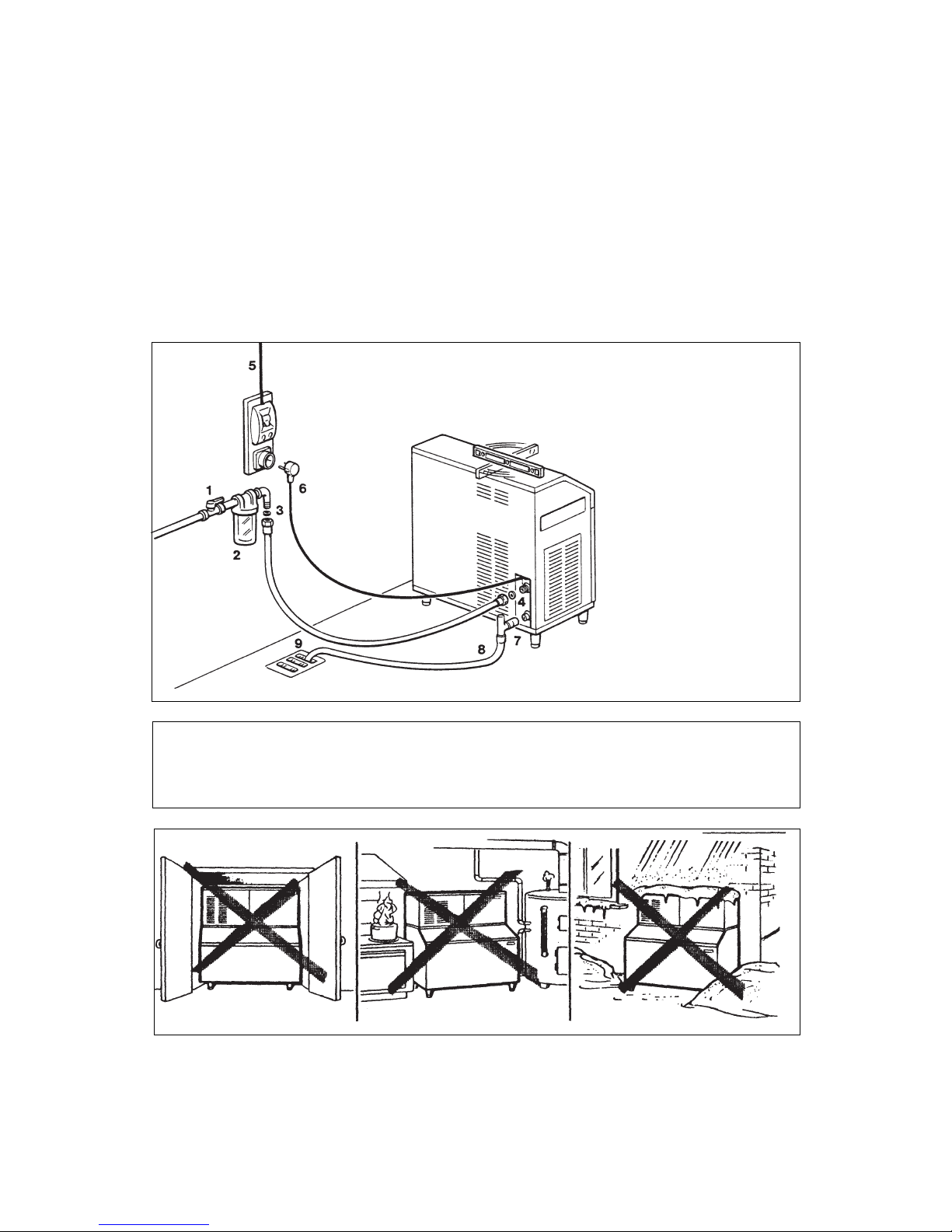
G. INSTALLATION PRACTICE
1. Hand shut-off valve
2. Water filter
3. Water supply line
(flexible hose)
4. 3/4" GAS male fitting
5. Power line
6. Main switch
7. Drain fitting
8. Vented drain
9. Open trapped vented
drain
WARNING. This icemaker is not designed for outdoor installation and will not function in
ambient temperatures below 10°C (50°F) or above 40°C (100°F).
This icemaker will malfunction with water temperatures below 5°C (40°F) or above 35°C
(90°F).
Page 8
Page 8
2
1
L
N
COMPRESSOR
9
10
11
12
13
3
4
5
6
7
8
CONTACTOR COIL
GEAR MOTOR
FAN MOTOR
ELECTRONIC
CARD
RELAYS
TRIAC
RESET
S E N S O R S
DATA PROCESSOR
WATER
LEVEL
GEAR MOTOR ROTATION
CONDENSER TEMP.
EVAPORATOR TEMP.
ICE LEVEL CONTROL
TRANSF.
T>1°C
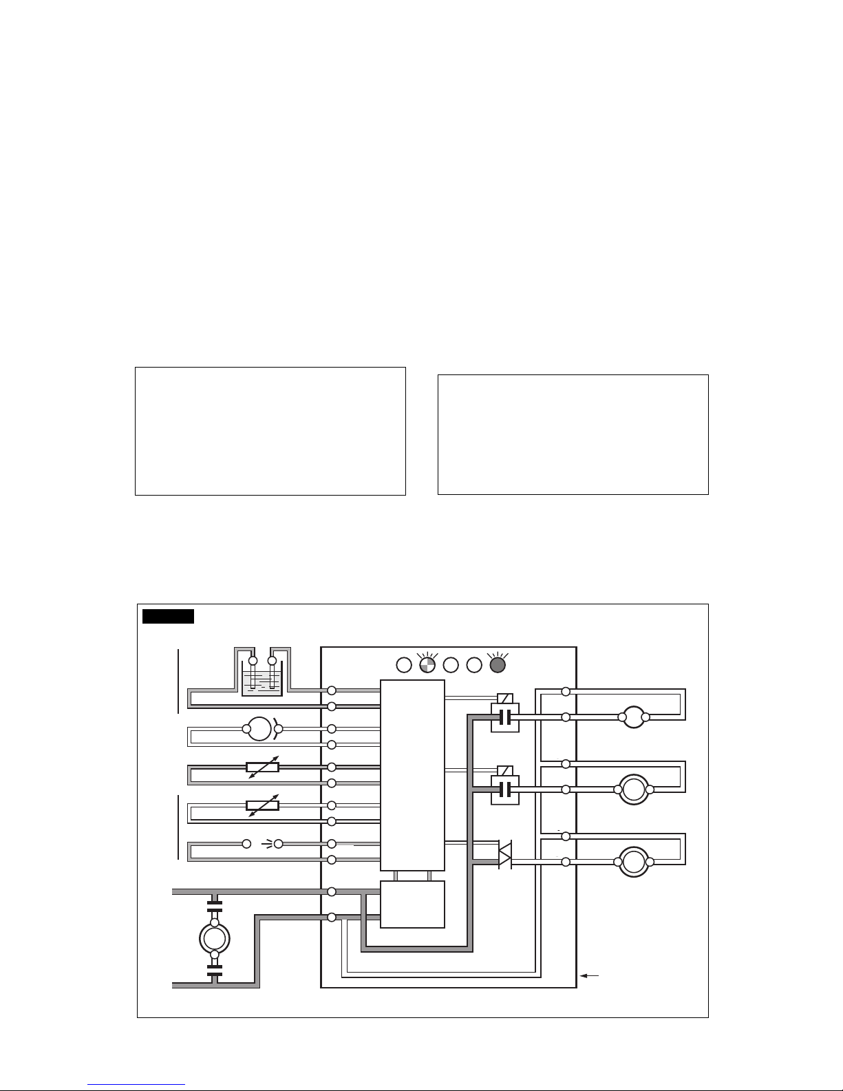
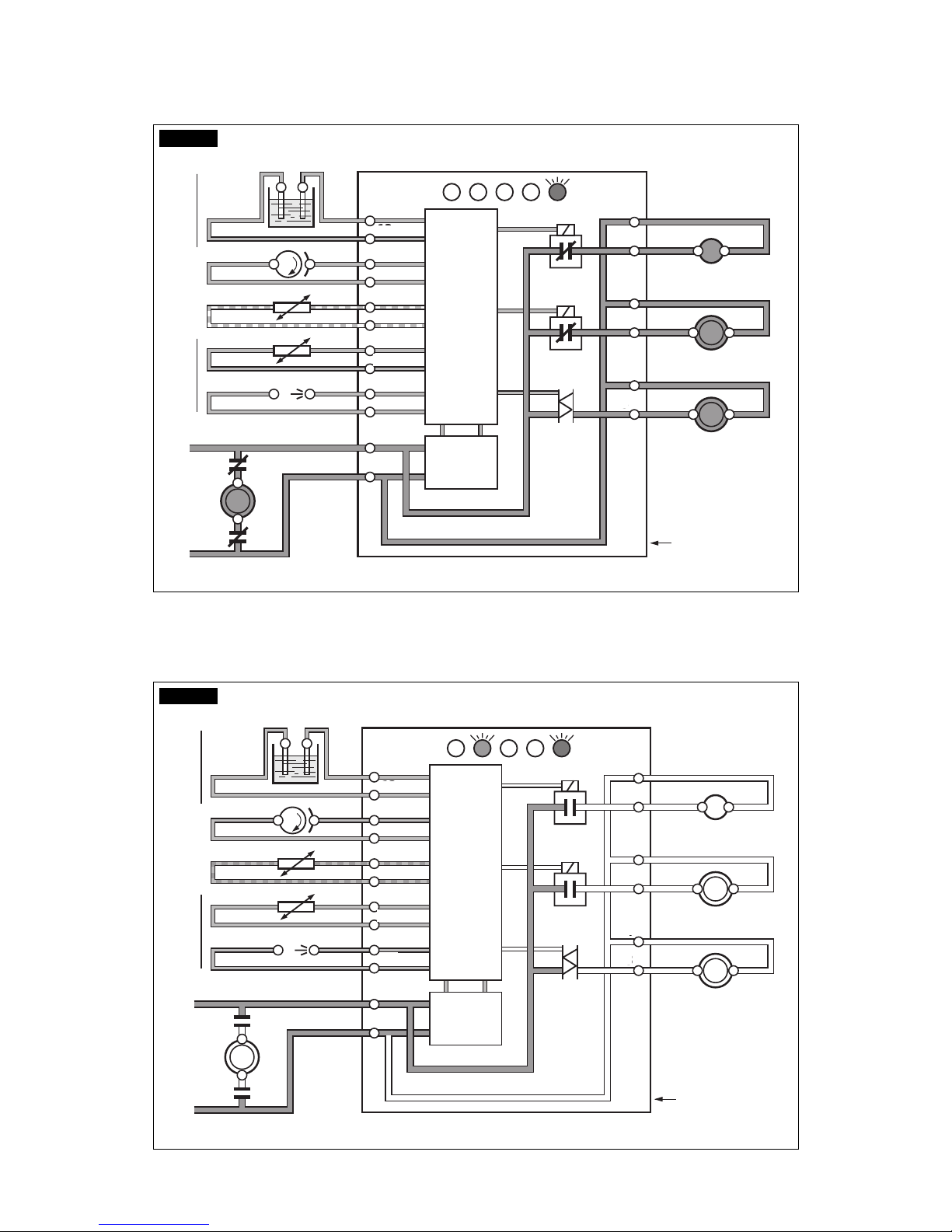
OPERATING INSTRUCTIONS
B. Elapsed the 3 minutes - stand by period - the
unit starts operating with the activation in
sequence of the following assemblies:
GEAR MOTOR
COMPRESSOR
FAN MOTOR (if unit is an air cooled version)
kept under control by the condenser temperature sensor which has its probe within the condenser
fins (Fig.2).
C. After 2 or 3 minutes from the compressor
start up, observe that flaker ice begins dropping
off the ice spout to fall into the storage bin.
NOTE. The first ice bits that drop into the ice
storage bin are not so hard as the evaporating
temperature has not yet reached the correct
operating value. It is necessary to allow the
ice - just made - to cure itself and wait for
about ten minutes for the evaporating temperature to reach the correct value so to
make more hard bits of ice.
L
N
11
10
9
1
2
7
8
6
5
4
3
13
12
FIG. 1
START UP
After having correctly installed the ice maker and
completed the plumbing and electrical
connections, perform the following “Start-up”
procedure.
A. Open the water supply line shutoff valve and
put the unit under electrical power by moving the
main switch, on the power supply line, to the ON
position.
The first LED - GREEN - will glow to signal that
unit is under power.
NOTE. Every time the unit is put under
power, after being kept for sometime in shutoff conditions (electrically disconnected) the
RED LED will blink for 3 minutes after which
the unit will start up with the immediate
operation of the gear motor assembly and,
after few seconds, of the compressor assy
(Fig.1).
Page 9
Page 9
FIG. 2
2
1
L
N
COMPRESSOR
9
10
11
12
13
3
4
5
6
7
8
CONTACTOR COIL
GEAR MOTOR
FAN MOTOR
ELECTRONIC
CARD
RELAYS
TRIAC
RESET
S E N S O R S
WATER
LEVEL
GEAR MOTOR ROTATION
CONDENSER TEMP.
EVAPORATOR TEMP.
ICE LEVEL CONTROL
TRANSF.
T 40÷50°C
DATA PROCESSOR
L
N
11
10
9
1
2
7
8
6
5
4
3
13
12
FIG. 3
2
1
L
N
COMPRESSOR
9
10
11
12
13
3
4
5
6
7
8
CONTACTOR COIL
GEAR MOTOR
FAN MOTOR
ELECTRONIC
CARD
RELAYS
TRIAC
RESET
S E N S O R S
WATER
LEVEL
GEAR MOTOR ROTATION
CONDENSER TEMP.
EVAPORATOR TEMP.
ICE LEVEL CONTROL
TRANSF.
T>75°C
DATA PROCESSOR
L
N
11
10
9
1
2
7
8
6
5
4
3
13
12
 Loading...