


®
Ice Bear
30 Unit
Application Guide
for models:
IB30A-521
IB30A-523
IB30A-543
F004_C © Ice Energy, Inc., 2009. All Rights Reserved. 4May09
Phone: (877) 542-3232
Fax: (970) 545-3634
Email: productservices@ice-energy.com
www.ice-energy.com

Industry Recognition
A
Consortium of US Federal Labs
WORLD’S BEST TECHNOLOGIES,
Gold Award, 2004
ENERGY VENTURE FAIR
Most Promising Company Award,
2003, 2004, 2005
Copyright, Notices, and Trademarks
No reproduction/distribution without permission.
While this information is presented in good faith and believed to be accurate, Ice Energy disclaims the implied
warranties of merchantability and fitness for a particular purpose and makes no express warranties except as may be
stated in its written agreement with and for its customers.
In no event is Ice Energy liable to anyone for any indirect, special or consequential damages. The information and
specifications in this document are subject to change without notice. The information and specifications in this
document are subject to change without notice. Visit www.ice-energy.com
Ice Energy, Ice Bear, and CoolData are registered trademarks and Ice-Ready, Ice-Coil, and Hybrid Cooling are
trademarks of Ice Energy, Inc. Other brand or product names are trademarks of their respective owners.
CALIFORNIA TITLE 24 – 2005
Optional Compliance Measure
Energy Efficiency Standards, 2006
FLEX YOUR POWER AWARD
for Permanent Peak Power Shifting, 2007
ASHRAE / ARI
AHR Expo
Product of the Year, 2004
Energy Management
Green Building Innovation
ward 2009
© Ice Energy, Inc., 2009. All Rights Reserved.
to ensure that you have the latest version.
TOP-10 GREEN BUILDING
Product of 2005
BuildingGreen Magazine
NORTHERN COLORADO
BUSINESS REPORT
Innovative Business Award, 2005
ii Ice Bear® 30 Unit Application Guide

Table of Contents
Introduction ................................................................................................................................................... 1
Ice Bear
A Few of the Unique Installation & Startup Considerations ........................................................................ 3
Ice Bear
Applications .................................................................................................................................................. 9
Controls and Sequence of Operation .......................................................................................................... 12
Product Data and Specifications ................................................................................................................. 17
Engineering Data ........................................................................................................................................ 21
Applying an Ice Bear
Equipment Selection ................................................................................................................................... 24
Installation Considerations .......................................................................................................................... 25
Appendix A – Cooling Load Profiles ......................................................................................................... 33
Appendix B – Guide Specifications ............................................................................................................ 35
Appendix C – Ice Bear 30 Unit Equipment Schedule ................................................................................. 37
Appendix D – Title 24 Building Energy Standards Models ....................................................................... 38
Appendix E – Ice-Ready RTU & Ice-Coil Performance Data .................................................................... 39
®
30 Unit Overview ......................................................................................................................... 2
Definitions of Terms ................................................................................................................................. 2
®
30 Unit Ratings by Ton-hour ........................................................................................................ 3
Ice Bear
Approvals and Code Compliance ............................................................................................................. 4
Ice Bear
®
30 Unit Features ....................................................................................................................... 4
®
30 Unit Components ................................................................................................................. 5
Modes of Operation .................................................................................................................................. 6
Application Parameters ............................................................................................................................. 9
Typical Applications ............................................................................................................................... 10
Sample Ice Bear
Control Schematic .................................................................................................................................. 12
CoolData
®
®
Unit Configurations ................................................................................................... 10
Controller.............................................................................................................................. 14
Sequence of Operation ............................................................................................................................ 15
Ice Bear
Ice Bear
®
30 Unit Ambient Temperature Operating Ranges .................................................................. 21
®
30 Unit ETL Certified Performance Data .............................................................................. 21
®
30 Unit ................................................................................................................... 22
Airside Options ....................................................................................................................................... 22
Ice-Ready™ Rooftop Units .................................................................................................................... 24
Minimum Clearances .............................................................................................................................. 25
Lifting ..................................................................................................................................................... 26
Mounting ................................................................................................................................................ 28
Minimum Requirements for Connection of CoolData
®
Controller Wiring ............................................ 32
Sample Load Profile Spreadsheet ........................................................................................................... 34
Ice Bear® 30 Unit Application Guide iii

List of Figures
Figure 1 – Ice Bear® 30 Unit External View ........................................................................................................ 5
Figure 2 – Ice Bear® 30 Unit Internal View.......................................................................................................... 5
Figure 3 – Refrigerant Flow Schematic – Ice Make Mode ................................................................................... 7
Figure 4 – Refrigerant Flow Schematic – Ice Cooling Mode ............................................................................... 8
Figure 5 – Ice Bear®` 30 Unit (Parallel) with Ice-Ready™ Rooftop Unit .......................................................... 10
Figure 6 – Redundant (Parallel) Split System ..................................................................................................... 11
Figure 7 – Control Schematic ............................................................................................................................. 12
Figure 8 – Single Zone, Single-stage Thermostat with Economizer and Backup Condensing Unit ................... 13
Figure 9 – Single Zone, Two-stage Thermostat with Economizer and Backup Condensing Unit ..................... 13
Figure 10 – CoolData® Controller ...................................................................................................................... 14
Figure 11 – Ice Bear® 30 Unit Dimensions Rear & Side Views ......................................................................... 18
Figure 12 – Ice Bear® 30 Unit Dimensions Top View ....................................................................................... 18
Figure 13 – Ice Bear® 30 Unit Dry Center of Gravity (Left) .............................................................................. 19
Figure 14 – Ice Bear® 30 Unit Dry Center of Gravity (Top) .............................................................................. 19
Figure 15 – Ice Bear® 30 Unit Wet Center of Gravity (Left) .............................................................................. 20
Figure 16 – Ice Bear® 30 Unit Wet Center of Gravity (Top) .............................................................................. 20
Figure 17 – Ice Bear® 30 Unit with an Ice-Ready™ Rooftop Unit .................................................................... 22
Figure 18 – Ice Bear® 30 Unit with an Additional (Slab) Ice-Coil™ ................................................................. 23
Figure 19 – Ice Bear® 30 Unit with an Additional (“N”) Ice-Coil™ .................................................................. 23
Figure 20 – Ice Bear® 30 Unit with a Ductless Liquid Overfeed Coil ................................................................ 24
Figure 21 – Minimum Clearances for Unit-mounted Service Disconnect .......................................................... 25
Figure 22 – Minimum Clearances for Remotely Mounted Service Disconnect ................................................. 26
Figure 23 – Ice Bear® 30 Unit Lifting Points ..................................................................................................... 27
Figure 24 – Recommended Spreader Bar Configuration .................................................................................... 27
Figure 25 – Minimum Recommended Concrete Pad Dimensions ...................................................................... 28
Figure 26 –Sample Precast Concrete Pad ........................................................................................................... 29
Figure 27 – Ice Bear® 30 Unit on Structural Curb with Cap .............................................................................. 30
Figure 28 – Ice Bear® 30 Unit Base Dimensions ................................................................................................ 31
Figure 29 – Ice Bear® 30 Unit Base Cross Section ............................................................................................. 31
Figure 30 – Design-Day Cooling Load Profile (Example) ................................................................................. 33
Figure 31 – Sample Load Profile ........................................................................................................................ 34
iv Ice Bear® 30 Unit Application Guide

Introduction
Introduction
Thermal Energy Storage (TES) is a well-recognized energy management tool that transfers a large portion
of the electricity required for air conditioning from high-price, on-peak hours to low-price, off-peak
hours. TES systems using ice storage allow an air conditioning system to operate during off-peak hours,
transferring clean and less expensive electrical energy into stored energy. The stored cooling energy in
the ice is later delivered to provide air conditioned comfort during on-peak hours when electricity prices
are higher and electrical power is limited, less reliable, and more polluting.
Traditionally, TES systems have benefited only large energy users, such as hospitals, large office
buildings, college campuses, and schools. The ICE BEAR
®
30 unit was developed specifically so that
buildings with small air conditioning and power requirements can receive comparable energy and
environmental benefits using a variety of packaged rooftop and split system air conditioners.
Thermal Energy Storage systems address the electrical system problems that other energy efficiency
measures do not address, in particular, resource allocation to meet the supply and demand of electricity.
Peak energy costs and emission concerns will continue to be a problem for the foreseeable future. Many
utilities offer rate structures that encourage energy management systems such as TES. Time-of-Use
(TOU) rates have become standard tariffs offered by many utilities. The substantial energy price
difference between on-peak and off-peak periods provide a significant financial incentive for using some
form of thermal energy storage. The higher costs of peak electricity reflect the pollution mitigation costs
associated with the higher emissions rates of peak energy generation.
A growing number of states are adopting energy efficiency standards above and beyond the federal
appliance standards. For example, the California Building Energy Efficiency Standards “performance
approach” uses a modified ASHRAE 90.1 methodology to establish the allowable energy consumption of
a proposed building project as compared the energy consumption of a minimally-compliant of a similar
building of similar occupancy, construction type and location. California’s Title 24 Standards estimate a
proposed building’s energy budget using an hourly time-of-use methodology and assigns a unique source
energy multiplier for each hour of the year to arrive at an estimate of the amount of source energy
required to provide the energy needs of the proposed building. The utility’s complete electricity network
costs, such as generation, transmission and distribution, and environmental mitigation are estimated for
each hour of the year establishing a Time Dependent Valuation (TDV) of energy. The resulting
calculation estimates a more accurate hourly cost and environmental impact of building energy
consumption. An hourly TDV multiplier for each of the state’s 16 climate zones translates site energy use
into a more accurate approximation of total source energy costs. When this TDV multiplier is applied to
an Ice Bear unit and conventional air conditioning systems of the equal capacity, the ice storage system
has as much as 22 times more TDV energy savings potential during peak periods.
Utility cost savings are clearly just one of the benefits provided by the Ice Bear unit. Ice storage plays a
significant role in obtaining certification points for the United States Green Building Council’s LEED
program. The Ice Bear unit’s superior cooling comfort, reliability, and reductions in the energy budget
can earn one to five Energy and Atmosphere Credits and up to 6 credits in other categories.
Ice Bear® 30 Unit Application Guide 1
®

Ice Bear® 30 Unit Overview
Ice Bear® 30 Unit Overview
The Ice Bear® 30 unit is an off-the-shelf hybrid condensing unit for use with direct expansion air
conditioning systems. The Ice Bear unit is designed to store energy at night and then shift the on-peak
electrical energy of a condensing unit common to packaged rooftop, split, and mini-split systems. A
typical application will shift the electrical energy consumed by a 5-ton scroll compressor and its
associated condensing unit fans operating under full load conditions for 6 hours continuously.
Electrically, the Ice Bear unit shifts approximately 30 kW-hours of energy to the off-peak, thus reducing
the on-peak demand by about 6 kW for six hours.
The Ice Bear unit runs its integral condensing unit for about 10 hours continuously, during the coolest
part of the night, to store energy in the form of ice (30 latent ton-hours). The control signal from the
thermostat or building management system is received by the Ice Bear unit’s CoolData
Based on the time-of-day, or upon a command to shed electrical demand initiated by the utility, the
controller determines if the Ice Bear hybrid condensing unit or the electrically operated condensing unit
will operate. In the case of the Ice Bear unit, it pumps enough oil free R-410A refrigerant to an Ice-Coil
evaporator to provide effective cooling for up to 5 tons of continuous load for six hours, using less than
300 watts of power. A unique and important design feature is the Ice Bear unit’s cooling performance
independent
of outdoor ambient or rooftop temperature; in other words, it can be 75 °F or 140 °F and the
Ice Bear unit and its associated Ice-Coil’s cooling performance (5-ton rating) is unchanged.
®
controller.
Definitions of Terms
Base System: A refrigerant based, direct expansion (DX) air conditioning system, commonly referred to
as a packaged rooftop unit, split system, or mini-split system. A typical base system includes a
condensing unit, an evaporator, a blower, and controls.
Ice-Coil™ Kit: An Ice-Coil and ancillary equipment needed to convert a packaged rooftop unit into an
Ice-Ready Rooftop Unit.
Ice-Coil™: A flooded evaporator coil provided by Ice Energy, or modified to Ice Energy’s
specifications. The Ice-Coil is dedicated to the Ice Bear unit and is sometimes referred to as a liquid
overfeed evaporator coil.
Ice-Cooling: The process whereby the Ice Bear unit’s stored ice cools the refrigerant used to provide
cooling to a building space during peak energy hours (typically noon to 6pm).
Ice-Make: The nighttime process by which the Ice Bear unit converts its tank of water into a tank of ice
to be used for cooling the next day during the peak energy hours (typically noon to 6pm).
Ice-Ready™ Rooftop Unit: A packaged rooftop unit modified to include an Ice-Coil.
Multi-Stage System: A packaged rooftop unit, typically greater than 5 tons, that includes multiple
independent refrigeration circuits, for example a 10-ton unit with two 5-ton circuits.
Peak Shifting: Shifting electric load from the utility defined on-peak period to the off-peak period. OnPeak hours are typically noon through 6 pm.
Redundant Coil: The addition of an Ice-Coil to a packaged rooftop unit or split system.
®
Summer Mode: The CoolData
available during peak energy hours.
controller’s programming is optimized to ensure that stored cooling is
Standard Circuit: A common DX refrigeration circuit that includes an evaporator coil, expansion
device, and condensing unit.
2 Ice Bear® 30 Unit Application Guide

A Few of the Unique Installation & Startup Considerations
Ton-hours: Capacity in tons times the number of hours (e.g., 5 tons for 6 hours = 30 ton-hours); an
important design consideration for fixed capacity storage units such as the Ice Bear unit.
Winter Mode: The CoolData controller is programmed to extend the Ice Cooling hours to more fully
utilize the stored cooling capacity of the unit.
A Few of the Unique Installation & Startup Considerations
• In addition to the Base System, an Ice-Coil must be used, which is typically a Redundant Coil.
o A flooded evaporator coil is provided by Ice Energy, or modified to Ice Energy’s
specifications, or included as part of an Ice-Ready Rooftop Unit, whose sole purpose is to
connect to the Ice Bear unit. Uniquely, an Ice-Coil does not use any type of expansion
device (orifice, TXV, or EEV); hence the term liquid overfeed or flooded coil. A mixed
phase of liquid and vaporized refrigerant may return to the Ice Bear unit.
• Length, Sizing, and Insulation of the refrigerant supply and return line sets.
o The Ice Bear unit may be located on the ground or on the roof in close proximity to the
Ice-Coil; there are distance and elevation limitations to consider. A unique feature of the
Ice-Coil circuit is that it is charged with oil free
R-410A refrigerant.
o The liquid supply line from the Ice Bear unit to the Ice-Coil and the vapor return line
from the Ice-Coil to the Ice Bear unit are uniquely sized to Ice Energy’s design
specifications. Both the liquid supply and the vapor return line sets must be insulated.
• When to fill with water and its associated weight
o One of the last steps
in the startup sequence is to fill the Ice Bear unit with about 450
gallons of tap water. When to fill the Ice Bear unit is important; filling too soon could
cause significant and costly damage to the unit.
o The filled weight of the Ice Bear unit is an important consideration for both ground
mount and roof mount applications.
• Remote Monitoring and Control
o The Ice Bear unit is centrally monitored and may be controlled remotely. To enable this
feature, the unit must be connected to the Ice Energy Network Operations Center by a
wired or by wireless data service (such as the Internet). Typically, a wireless (3G) data
connection is installed and configured by Ice Energy. Provision may be required for an
external antenna and/or an alternate service (Internet) connection in areas where coverage
is inadequate.
• Heat Pumps
o When applying an Ice Bear 30 unit to a heat pump, the Ice Bear unit must have a
dedicated (redundant) Ice-Coil.
Ice Bear® 30 Unit Ratings by Ton-hour
Importantly, the Ice Bear unit has a limited amount of cooling capacity and therefore proper consideration
of the building’s cooling load profile is a critical step and must not be overlooked. The Ice Bear unit
should not be used as the only source of cooling for typical office building, restaurant, and retail designs.
• Storage capacity: 30 ton-hours at a peak load of 5 tons
o 5 tons for 6 hours, or 4 tons for 7.5 hours, or 3 tons for 10 hours
• Instantaneous output capacity is unaffected by ambient temperature
Ice Bear® 30 Unit Application Guide 3

Ice Bear® 30 Unit Ratings by Ton-hour
Ice Bear® 30 Unit Features
The Ice Bear 30 unit is a highly flexible TES system which can be installed “out-of-the box” in a wide
variety of configurations and environmental settings.
• Storage capacity: 30 ton-hours at a peak capacity of 5 tons
• Remotely programmable Ice Make/Ice Cooling schedules
• Remote monitoring of operation and equipment performance
• Instantaneous output capacity unaffected by ambient temperature
• Versatile staging
o Offloading a single stage of a two-stage Ice-Ready™ rooftop unit
• Rooftop or ground mounting options
• Maximum refrigerant line length: up to 150 feet between Ice Bear 30 and rooftop unit
• Maximum vertical lift: up to 35 feet above the Ice Bear 30 unit.
• Electrical consumption:
o On-peak Ice Cooling: 300 watts (nominal)
o Off-peak Ice Make: 3,470 watts (typical at 75 °F)
• Three models:
o IB30A-521—208/230V, 1 phase
o IB30A-523—208/230V, 3 phase
o IB30A-543—460V, 3 phase
Approvals and Code Compliance
Ice Energy has contracted with Intertek’s ETL SEMKO division to provide independent
confirmation of the capabilities of the Ice Bear 30 Unit. See Ice Bear® 30 Unit ETL Certified
Performance Data later in this manual.
The Ice Bear 30 unit has been approved for use as a Title 24 Compliance Option in the state of California.
Refer to Appendix D – Title 24 Building Energy Standards Models for more information.
4 Ice Bear® 30 Unit Application Guide
Ice Bear® 30 Unit Ratings by Ton-hour
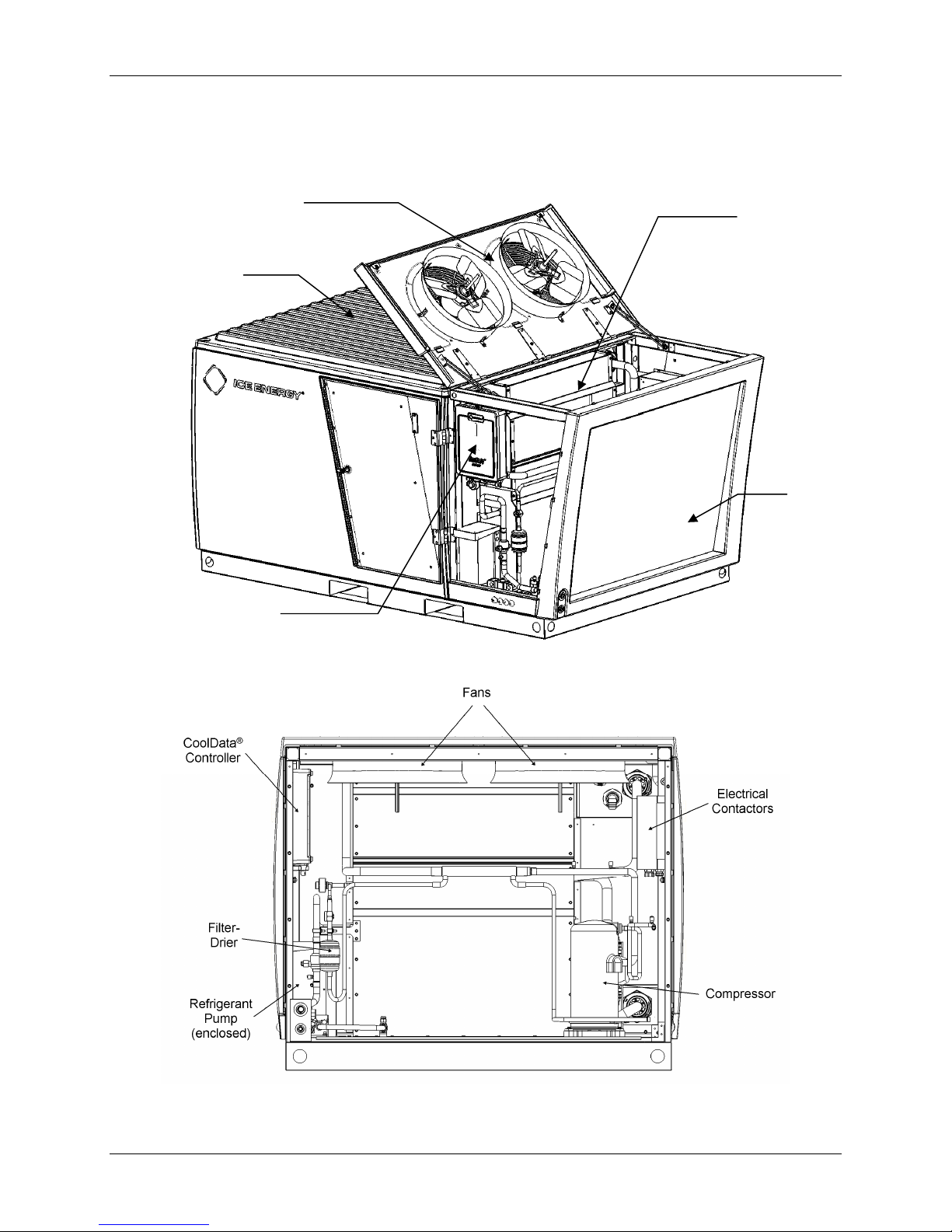
Ice Bear® 30 Unit Components
Fans
Ice Storage
Tank
CoolData®
Controller
Figure 1 – Ice Bear
®
30 Unit External View
Refrigerant
Management
System (RMS)
Ice-Make
Condensing
Coil
Figure 2 – Ice Bear
Ice Bear® 30 Unit Application Guide 5
®
30 Unit Internal View

Ice Bear® 30 Unit Ratings by Ton-hour
Modes of Operation
The Ice Bear unit is capable of operating in the following modes:
• Ice Make mode
o Night (off-peak) operation
o Storing energy, charging, making ice
• Ice Cooling mode
o Peak period operation (call for cooling)
o Discharging the stored energy, melting the ice
Note that Ice Make mode may also be referred to as “Ice Charge” or “Ice Build”. Ice Cooling mode may
also be known as “Ice Discharge” or “Ice Melt”.
Ice Make Mode
During Ice Make mode, the integral and factory pre-charged Ice Bear condensing unit (R-410A
refrigerant and miscible oil) provides low temperature refrigerant to the Ice Bear unit’s Refrigeration
Management System (RMS). On the secondary side of the RMS, a separate, oil-free R-410A charge
automatically circulates through a heat exchanger until the tap water freezes into a solid block of ice.
Ice make is typically 10 hours for a full 30 ton-hour charge and is made during the coolest time of night
or when electrical utility rates are at their lowest, or off-peak times.
Why Make Ice?
It takes 1 BTU of energy to lower the temperature of one pound of water 1 °F.
For example, it takes 1 BTU of energy to lower the temperature of one pound of water from 38 °F to
37 °F.
However, it takes 144 BTU’s of energy to change the state of one pound of water from a liquid to a solid
(ice). Therefore, it takes 144 BTU’s of energy to change the state of one pound of 32 °F water from a
liquid into ice.
The Ice Bear unit’s block of ice is sized to store 30 ton-hours of energy. There are 12,000 BTU’s per ton,
so the 30 ton-hours of stored energy are equivalent to 360,000 BTU’s. A 60,000 BTU/hour cooling load
or exactly the cooling load of one 5-ton Ice Coil (12,000 BTU’s / ton x 5 tons) running for six hours
would consume the entire Ice Make or 360,000 BTU’s of stored energy.
6 Ice Bear® 30 Unit Application Guide

Ice Bear® 30 Unit Ratings by Ton-hour
Figure 3 – Refrigerant Flow Schematic – Ice Make Mode
Ice Bear® 30 Unit Application Guide 7

Ice Bear® 30 Unit Ratings by Ton-hour
Ice Cooling Mode
During Ice Cooling mode, the integral Ice Bear condensing unit is switched off and typically one 5-ton
condensing coil on the Base System is locked out. The Ice Cooling circuit, which includes an ice-on-coil
heat exchanger, a refrigerant pump, and Ice-Coil™ are physically isolated from the Ice-Make circuit and
its refrigerant charge by a unique receiver/separator. When there is a request for cooling, a refrigerant
pump circulates the oil-free liquid R-410-A refrigerant through the liquid supply line to an Ice-Coil
located in the air stream. Typically this is a Redundant Ice-Coil installed into a packaged rooftop unit or a
slab coil mounted in the air supply duct. The vapor return line returns vaporized or mixed phase
refrigerant to the Ice Bear unit’s ice-on-coil heat exchanger where it melts ice and is condensed back into
its liquid state.
Figure 4 – Refrigerant Flow Schematic – Ice Cooling Mode
8 Ice Bear® 30 Unit Application Guide

Applications
Applications
Application Parameters
There are parameters that apply to every Ice Bear unit installation. Below is a list of installation
constraints that need to be strictly followed to ensure proper operation and reliability of the Ice Bear unit.
Installation constraints for the Ice Bear unit:
Item Specification
Line Set Sizing Ice-Coil™ supply line = 1/2”
Ice-Coil return line = 7/8”
(Both lines must be insulated.)
Maximum overall
length (to Ice-Coil)
Maximum vertical head
Ice-Coil supply line
Maximum vertical head
Ice-Coil below Ice Bear
unit
Maximum fittings per
line (supply & return)
Minimum insulation
wall thickness
Isolation valves with
service ports
Sight Glasses Install sight glasses in the Ice-Coil supply and return lines, as close
150 ft including vertical head (maximum 20 fittings)
35 ft
20 ft
20
1/2” or minimum required by local code, whichever is greater.
Isolation valves with service ports must be field installed in the Ice-
Coil supply and return lines, as close as possible to the coil.
to the Ice Bear unit as possible.
Any deviations from the above parameters require review by Ice Energy’s Technology department.
NOTE: When applying an Ice Bear 30 unit to a heat pump, the Ice Bear unit must have a dedicated
(redundant) Ice-Coil.
Ice Bear® 30 Unit Application Guide 9

Applications
Typical Applications
• Single zone
• Single Ice Bear unit or multiple Ice Bear units
• Partial storage system in a multi-stage configuration (displacing one or two stages of a multi-stage
system)
NOTE: When applying an Ice Bear 30 unit to a heat pump, the Ice Bear unit must have a dedicated
(redundant) Ice-Coil.
Sample Ice Bear® Unit Configurations
• Ice Bear unit (parallel) with Ice-Ready™ rooftop unit
• Redundant (parallel) split system
Ice Bear® 30 Unit (Parallel) with an Ice-Ready™ Rooftop Unit
The Ice Bear unit integrates with a modified packaged rooftop unit called an Ice-Ready rooftop unit. The
Ice-Ready rooftop unit, illustrated in the figure below, is a standard rooftop unit modified to include an
additional liquid overfeed coil (Ice-Coil™) that is dedicated to the Ice Bear unit. Specific systems are
available from name brand unit manufacturers as Ice-Ready rooftop units. For a list of currently
approved Ice-Ready rooftop units, and Ice-Coil kits, refer to the Ice-Ready™ Products Selection Guide
(Ice Energy form F091) or visit www.ice-energy.com
Product Services (email productservices@ice-energy.com
. For other airside options, contact Ice Energy
or call (877) 542-3232).
Figure 5 – Ice Bear
10 Ice Bear® 30 Unit Application Guide
®
` 30 Unit (Parallel) with Ice-Ready™ Rooftop Unit

Applications
Redundant (Parallel) Split System
In a redundant split system, the Ice Bear unit provides cooling as part of a separate and parallel redundant
refrigerant loop. It is only designed to take on a load for a designated period of time. The liquid overfeed
Ice-Coil is located downstream of the existing or “regular” standard DX coil.
The Ice Bear unit handles the designated load during peak load conditions, while the remainder of the
system handles the cooling load during the remainder of the day.
Figure 6 – Redundant (Parallel) Split System
Ice Bear® 30 Unit Application Guide 11

Controls and Sequence of Operation
Controls and Sequence of Operation
Control Schematic
Figure 7 – Control Schematic
12 Ice Bear® 30 Unit Application Guide

Controls and Sequence of Operation
Control Configuration Example 1
Figure 8 – Single Zone, Single-stage Thermostat with Economizer and Backup Condensing Unit
Control Configuration Example 2
Figure 9 – Single Zone, Two-stage Thermostat with Economizer and Backup Condensing Unit
Ice Bear® 30 Unit Application Guide 13

Controls and Sequence of Operation
CoolData® Controller
Features
The CoolData controller is an advanced control system that provides both controlling and monitoring
functions for the Ice Bear unit. Also, CoolData has bidirectional control and communication capabilities
for Smart Grid integration, including:
• configuration management
• real-time control
• advanced and optimal control
• real-time status, submetering, and monitoring
• performance analysis and automated diagnostics
• equipment health management
• event capture and analysis
• push and polling communications
• physical & cyber security
• data integrity readied for transactions with enterprise-level communication
Ethernet Cable
Connector
LED Indicators
Figure 10 – CoolData
®
Controller
14 Ice Bear® 30 Unit Application Guide

Controls and Sequence of Operation
Sequence of Operation
The Ice Bear unit is thermostatically controlled in the same manner as a conventional DX system. The
controller for the Ice Bear unit regulates the refrigerant and the unit’s internal components similarly to a
conventional DX air conditioning system. When a packaged unit is equipped with an economizer, the
economizer and the HVAC system will operate normally in collaboration with the Ice Bear unit.
The Ice Bear unit’s programmable controller responds to a single- or two-stage thermostat input. Either
configuration allows the Ice Bear unit to control the base system (allowing DX cooling during Ice Make,
for example). With a two-stage input, the Ice Bear unit and the additional system may be set up to
provide cooling simultaneously; whereas, with a single-stage input, only one system will provide cooling
at any given time. A single stage DX system connected to an Ice Bear unit is referred to as the backup
system. In a two-stage DX system with matching thermostat, the second DX system is referred to as a
parallel system. The programming for the Ice Bear unit’s internal controller is based on the desired Ice
Make and Ice Cooling operations. The Ice Bear unit can be configured to provide Ice Cooling for any
period of time consistent with the maximum cooling capacity, tank charge capacity, and tank recharge
requirements. The desired operating schedules are set prior to shipment or by a certified installer in the
field and can, if required, be reprogrammed remotely for optimization purposes.
The Ice Bear unit integrates with facility control systems and simple thermostats through traditional
24VAC signals, both for control and status feedback. No other communications to a facility management
system are required. The Ice Bear unit is unique as an energy storage device in that it is a fully packaged,
self-contained system. As such, it optimizes its performance independently of a facility management
system. Integration for Supervisory Control and Data Access (SCADA), additional monitoring, and other
advanced features are viable, but are not part of the standard offering.
For California Title 24 compliance applications, the programming is unalterable and operates within the
parameters of the specified product model. Control parameters are given at the factory.
Charging (Ice Make Mode)
Startup Sequence
1. Fan #1 starts and the Electronic Expansion Valve (EEV) is reset. (Charging LED blinks once.)
2. There is a 4 second delay.
3. Fan #2 starts.
4. Initial EEV position is set.
5. There is a 26 second delay.
6. Superheat set point is derived from the Condenser liquid temperature.
7. Compressor starts. (Charging LED blinks 3 times).
8. There is a 10 second delay.
9. EEV will start to control the system. (Charging LED is on solid.)
Full Charge Cutoff Sequence
1. Upon reaching charge cutoff pressure (typically 98.5 psia), the charging operation shuts down after
5 minutes.
2. The EEV is set to the closed position.
Ice Bear® 30 Unit Application Guide 15

Controls and Sequence of Operation
Cooling (Ice Cooling Mode)
Startup Sequence (call for cooling)
1. Refrigerant Pump and Solenoid Valve are energized and Water Pump starts.
2. Refrigerant Pump is initially set to minimum speed. (Cooling LED repeatedly blinks twice.)
3. There is a 10 second delay.
4. Refrigerant Pump is set to its final speed. (Cooling LED on solid until call for cooling ends, ice is
exhausted, or system transitions out of the configured ice cooling time window, as determined by
unit’s specific configuration.)
Shutdown Sequence (no call for cooling)
1. Water and Refrigerant Pumps shut down.
2. There is a 15 second delay.
3. Individual zone relay is closed.
Full Discharge Cutoff Sequence
1. Discharge cutoff condition is achieved; i.e., cutoff pressure is reached (typically 165 psia) or the
Tank water reaches a temperature of 48 °F (typical).
2. There is a 5 minute delay.
3. Refrigerant and Water Pumps are shut down.
4. There is a 15 second delay.
5. Individual zone relays are closed, if defined.
16 Ice Bear® 30 Unit Application Guide

Product Data and Specifications
Product Data and Specifications
Table 1. Ice Bear 30 Unit Cooling Performance
Maximum instantaneous cooling capacity 5 tons
Total storage module capacity 30 ton-hours
Maximum on-peak electrical demand (at maximum
application parameters, excluding crankcase heater)
Nominal on-peak electrical demand (typical installation) 300 watts
Ice Make/recharge time
(from fully melted tank of ice)
Table 2. Ice Bear 30 Unit Physical Properties
Dimensions (W x D x H) 100-1/2” x 61” x 49”
Weight (without water) 1,550 lb.
Weight (filled) 5,550 lb.
Load distribution (filled) 204 lb/linear ft
(156 lb. per ft
Water volume 475 gallons
Refrigerant charge, tank (Ice Cooling) 35 lb R-410A (factory)
Refrigerant charge, compressor (Ice Make) 11 lb 8 oz R-410A (factory)
Table 3. Ice Bear 30 Unit Electrical Properties
350 watts
11.5 hours at 75 °F
outdoor ambient temp.
2
)
Model System Type
IB30A-521
IB30A-523
IB30A-543
208/230V, 1φ
208/230V, 3φ
460V, 3φ
Minimum
Circuit
Ampacity
Maximum
Fuse
(MCA)
41.7 50
27.2 30
13.3 20
Table 4. Ice Bear 30 Unit Sound Ratings
-12
Outdoor Sound Power Level dB – (ref. 10
Overall
dBA
Octave Center Frequency
63 125 250 500 1000 2000 4000 8000
W)
IB30A 80 79.8 84.4 83.3 74.3 72.7 71.3 64.9 56.7
Notes:
1. Above ratings are values derived during Ice Making mode.
2. Compressor/condenser vibration isolation provided by OEM per equipment manufacturers’ standard specifications.
3. Outdoor sound data measured by Intertek in accordance with ARI Standard 370.
4. Ice Make ambient conditions for this test were 69 °F and 55% RH.
5. This test is not part of the ARI Certification.
6. Uncertified sound testing during Ice Cooling mode resulted in a level of 68 dBA.
Ice Bear® 30 Unit Application Guide 17

Product Data and Specifications
Figure 11 – Ice Bear
®
30 Unit Dimensions Rear & Side Views
Figure 12 – Ice Bear
®
30 Unit Dimensions Top View
18 Ice Bear® 30 Unit Application Guide

Product Data and Specifications
See the below figures for dry center of gravity.
Figure 13 – Ice Bear
®
30 Unit Dry Center of Gravity (Left)
Figure 14 – Ice Bear
®
30 Unit Dry Center of Gravity (Top)
Ice Bear® 30 Unit Application Guide 19

Product Data and Specifications
See the below figures for wet (water-filled) center of gravity.
Figure 15 – Ice Bear
®
30 Unit Wet Center of Gravity (Left)
®
Figure 16 – Ice Bear
30 Unit Wet Center of Gravity (Top)
20 Ice Bear® 30 Unit Application Guide

Engineering Data
Engineering Data
Ice Bear® 30 Unit Ambient Temperature Operating Ranges
Ice Make
• Performance tested Ice Make temperature range: 55 °F to 95 °F
• Enabled Ice Make temperature range: 15 °F to 115 °F
• Ice Make is automatically disabled below 15 °F or higher than 115 °F.
Ice Cooling
• Cooling performance is independent of ambient conditions above 15 °F.
• Ice Cooling is automatically disabled when ambient is below 15 °F.
Ice Bear® 30 Unit ETL Certified Performance Data
Table 5. Ice Make Capacity & Power at Ambient Temperature
Outdoor Temperature (°F)
Capacity Energy Capacity Energy Capacity Energy Capacity Energy Capacity Energy
Stored Consumed Stored Consumed Stored Consumed Stored Consumed Stored Consumed
(T-hrs) (kW-hr) (T-hrs) (kW-hr) (T-hrs) (kW-hr) (T-hrs) (kW-hr) (T-hrs) (kW-hr)
1 3.61 2.88 3.49 3.19 3.33 3.53 3.08 3.96 2.80 4.40
2 7.15 5.72 6.76 6.33 6.47 7.00 6.00 7.84 5.46 8.70
3 10.61 8.54 10.01 9.46 9.56 10.47 8.88 11.70 8.07 12.99
4 14.03 11.35 13.22 12.59 12.62 13.94 11.71 15.55 10.66 17.27
5 17.4 14.16 16.41 15.71 15.64 17.41 14.52 19.40 13.23 21.55
6 20.77 16.97 19.59 18.83 18.66 20.87 17.32 23.24 15.79 25.83
Time (hrs)
7 24.12 19.77 22.74 21.94 21.66 24.32 20.10 27.08 18.35 30.10
8 27.46 22.57 25.89 25.04 24.64 27.78 22.88 30.92 20.89 34.37
9 30.75 25.36 29.01 28.13 27.60 31.24 25.63 34.76 23.43 38.63
10 31.57 26.06 31.57 30.71 30.52 34.70 28.38 38.59 25.95 42.89
11 31.57 35.95 31.09 42.42 28.46 47.15
12 31.57 43.11 30.94 51.40
13 31.57 52.50
Actual Make Time (hrs) 9.24 9.84 10.36 11.17 12.25
Typical Demand (kW) 2.82 3.12 3.47 3.86 4.28
55° 65° 75° 85° 95°
Ice Bear® 30 Unit Application Guide 21

Applying an Ice Bear® 30 Unit
Applying an Ice Bear® 30 Unit
The Ice Bear 30 unit minimizes application considerations in that several airside solutions are available
that make it simple to take advantage of hybrid cooling technology. Each of the airside options shown
below involve adding a liquid overfeed coil that is dedicated to the Ice Bear unit, making the overall
solution redundant, capable of delivering 24 hours of cooling, if necessary. When load profiles permit
(i.e., when the Ice Bear unit can meet the entire cooling demand), one may apply the Ice Bear unit in a
standalone configuration.
You may apply the Ice Bear 30 unit with any of the following airside solutions. If the desired airside
solution is not listed below, contact Ice Energy Product Services (call 877-542-3232 or email
productservices@ice-energy.com
NOTE: When applying an Ice Bear 30 unit to a heat pump, the Ice Bear unit must have a dedicated
(redundant) Ice-Coil.
Airside Options
• Ice-Ready™ Rooftop Unit
• Dedicated Slab Liquid Overfeed Coil
• Dedicated “N” Liquid Overfeed Coil
• Dedicated Ductless Liquid Overfeed Coil
).
Ice-Ready™ Rooftop Unit
Figure 17 – Ice Bear
®
30 Unit with an Ice-Ready™ Rooftop Unit
22 Ice Bear® 30 Unit Application Guide

Applying an Ice Bear® 30 Unit
Slab Liquid Overfeed Coil
Figure 18 – Ice Bear
“N” Liquid Overfeed Coil
®
30 Unit with an Additional (Slab) Ice-Coil™
Figure 19 – Ice Bear
Ice Bear® 30 Unit Application Guide 23
®
30 Unit with an Additional (“N”) Ice-Coil™

Equipment Selection
Ductless Liquid Overfeed Coil
®
Figure 20 – Ice Bear
30 Unit with a Ductless Liquid Overfeed Coil
Equipment Selection
As described in the previous section, the Ice Bear unit may be paired with any of the following airside
options:
• Ice-Ready™ Rooftop Unit
• Slab Liquid Overfeed Coil
• “N” Liquid Overfeed Coil
• Ductless Liquid Overfeed Coil
Each of these airside options listed above includes an Ice-Coil™, which is a liquid overfeed coil designed
and tested to Ice Energy specifications.
Ice-Ready™ Rooftop Units
For a list of currently approved Ice-Ready rooftop units, and Ice-Coil kits, refer to the Ice-Ready™
Products Selection Guide (Ice Energy form F091) or visit www.ice-energy.com
options, contact Ice Energy Product Services (email productservices@ice-energy.com
877-542-3232).
For Ice-Ready rooftop unit performance data (including static pressure values), see Appendix E – Ice-
Ready RTU & Ice-Coil Performance Data at the end of this manual.
. For other airside
or call
24 Ice Bear® 30 Unit Application Guide

Installation Considerations
Installation Considerations
Minimum Clearances
In addition to the minimum clearances depicted in the figures that follow, ensure that a 60” vertical
clearance exists to provide for proper condenser fan operation.
NOTE: Local codes/regulations may prevail.
Figure 21 – Minimum Clearances for Unit-mounted Service Disconnect
Ice Bear® 30 Unit Application Guide 25

Installation Considerations
Figure 22 – Minimum Clearances for Remotely Mounted Service Disconnect
CAUTION
If a concrete pad is installed directly against building’s foundation, an approved expansion joint must be
installed to prevent possible noise transfer.
Lifting
Ice Energy recommends a 10’ spreader bar in an “H” configuration with two 6’- 8’ bars running
perpendicular for lifting. Any lifting method other than this one may cause damage to the exterior
components of the unit. Ice Energy is not responsible for any damage caused by alternative lifting
techniques (i.e., damage is not covered by the product warranty). Refer to the Ice Bear
Installation & Maintenance Guide for details.
26 Ice Bear® 30 Unit Application Guide
®
30 Unit

Installation Considerations
The Ice Bear unit’s lifting points are indicated in the figure below.
Lifting Points
Figure 23 – Ice Bear
®
30 Unit Lifting Points
Figure 24 – Recommended Spreader Bar Configuration
See Product Data and Specifications earlier in this manual for dry and wet (water-filled) center of gravity
dimensions.
Ice Bear® 30 Unit Application Guide 27

Installation Considerations
Mounting
The Ice Bear® 30 unit weights are as follows:
Ground Mounting
Provide leveling in compliance with local codes for clearance, easements, and soil compaction
restrictions. The Ice Bear unit must be level to within 1/8" in all directions.
Concrete Pad
• A concrete pad or other approved surface may be used, as designed and reviewed by a licensed
structural engineer.
• Refer back to Minimum Clearances.
• See Figure 25 for minimum recommended pad dimensions.
• Figure 26 provides a sample drawing of a precast concrete pad.
NOTE: Local codes/regulations may prevail.
Weight (without water) 1,550 lb
Weight (filled) 5,550 lb
Load distribution (filled) 156 lb per ft2
204 lb per linear ft
Figure 25 – Minimum Recommended Concrete Pad Dimensions
28 Ice Bear® 30 Unit Application Guide
Concrete
Pad
Ice Bear
Unit Base

Installation Considerations
CAUTION
If concrete pad is installed directly against building’s foundation, an approved expansion joint must be
installed to prevent possible noise transfer.
Ensure that roof drainage system does not undermine the Ice Bear unit’s foundation and that ALL gutters
and downspouts are properly placed and secured.
Ice Bear® 30 Unit Application Guide 29
Figure 26 –Sample Precast Concrete Pad

Installation Considerations
Rooftop Mounting
Follow structural drawings for proper location of the Ice Bear unit. Provide leveling and securing in
compliance with local codes. Level the Ice Bear unit to within 1/8" in all directions. Consult a Structural
Engineer.
Although the Ice Bear unit weighs approximately 5,500 lb, Ice Energy has successfully placed the
equipment on all standard engineered flat roofs with no modifications to the structural frame. Similar to
any piece of equipment to be placed on the roof, a structural analysis by a licensed structural engineer is
required by the permitting agency having jurisdiction over an installation.
Figure 27 illustrates an Ice Bear unit mounted on a curb with cap. Contact Ice Energy for details.
Figure 27 – Ice Bear
®
30 Unit on Structural Curb with Cap
30 Ice Bear® 30 Unit Application Guide

Installation Considerations
Figure 28 illustrates the base dimensions of the Ice Bear 30 unit to assist in designing a structural curb.
Figure 28 – Ice Bear
®
30 Unit Base Dimensions
14 ga (.075”)
Galvanized Steel
SECTION B
Figure 29 – Ice Bear
®
30 Unit Base Cross Section
Ice Bear® 30 Unit Application Guide 31

Installation Considerations
Minimum Requirements for Connection of CoolData® Controller
Wiring
The below items are the minimum requirements for basic common installations. Depending on the scope
of a given installation, additional wiring may be required. Consult plans and engineering drawings to
determine actual requirements. Contact Ice Energy Product Services (call (877) 542-3232) or email
productservices@ice-energy.com
• Conform to engineering layout drawings showing locations of wiring and thermostat.
• Document deviations in the Startup & Verification Report (F018).
• Use one #18AWG insulated 8 conductor cable between Ice Bear unit and each base unit (e.g., air
handler, packaged unit, ductless Ice-Coil) for control only.
• Use one #18AWG insulated (minimum 4 conductor) cable per Current Transducer and one
unshielded (UTP) CAT5e cable between each monitored base unit and the Ice Bear unit for
monitoring only.
• If an alternate data service connection is required, use one CAT5e cable between the Ice Bear unit
and the alternate data service (Internet) location.
) if you have questions.
32 Ice Bear® 30 Unit Application Guide

Appendix A – Cooling Load Profiles
Appendix A – Cooling Load Profiles
A design-day cooling load profile is an hour-by-hour listing of the loads for a 24-hour day. Conventional
air conditioning system sizing is based on the peak design cooling load for the year. Ice storage system
sizing is based on the maximum daily total cooling load (total ton-hours over a 24 hour period) as well as
the peak hourly load (tons). An understanding of the cooling load profile for each cooling circuit is
valuable when designing an Ice Bear unit.
6
5
4
Tons
3
2
1
0
1 2 3 4 5 6 7 8 9 101112131415161718192021222324
Time of Day
Figure 30 – Design-Day Cooling Load Profile (Example)
When designing a building cooling solution using an Ice Bear unit, you will need an hourly load profile
worksheet to determine the design-day cooling solution. You should consider two design days: the day
that requires the maximum total cooling over a 24 hour period and the day with the peak hourly load for
the year.
A load profile worksheet template is provided on the next page.
Oftentimes the Ice Bear unit is used to shift the maximum connected load, 5 tons for six consecutive
hours, coincident with the utilities’ most costly on-peak billing period, typically Noon – 6 pm. This is
especially true when displacing one stage of a multi-stage system in a location that has a high demand
(kW) charge.
Ice Bear® 30 Unit Application Guide 33

Appendix A – Cooling Load Profiles
y
d
g
A
Sample Load Profile Spreadsheet
The following blank spreadsheet is in the form recommended in Air-Conditioning and Refrigeration
Institute (ARI) Guideline T for design of Thermal Energy Storage (TES) systems. The designer should
use this type of spreadsheet and change the column headings to match the specific project. You may
expand the spreadsheet to include the hour-by-hour values for items such as: liquid flow, fluid
temperature, pressure drop, and condensing unit performance.
Time of Cooling Second Ice Ice Ambient Electric Electric
Da
0
1
2
3
4
5
6
7
8
9
10
11
12
13
14
15
16
17
18
19
20
21
22
23
Total
Loa
Profile Unit Ice Bear Ice Bear Periods
(Tons) (Tons) (Tons) (Tons) (db F) (kW)
Condensin
Melt Make
Unit Unit
ir Demand Data
34 Ice Bear® 30 Unit Application Guide
Figure 31 – Sample Load Profile

Appendix B – Guide Specifications
Appendix B – Guide Specifications
Ice Storage Air Conditioning (ISAC) System
Cooling Capacity: Nominal 30 ton-hrs, 5 ton capacity
Duty: exterior installation
Part 1 – General
1.01 SYSTEM DESCRIPTION
A. Outdoor rated ISAC system suitable for pad mounted on-the-ground or rooftop installation. The
ISAC replaces a standard compressor / condenser in order to disassociate system power
consumption from the cooling load profile. The unit will provide cooling to building(s) by
melting stored ice. Ice is made during off-peak periods by an integrated condensing unit, as
determined by an internal controller. Unit shall consist of an ice storage tank with means of heat
extraction and rejection (heat exchanger), R-410A refrigerant, refrigerant management system,
refrigerant pump, and a standard condensing unit.
1.02 QUALITY ASSURANCE
A. ISAC system shall be rated in accordance with established procedures for testing the Ice Make
and Ice Cooling performance accepted and approved by the California Energy Commission
B. ISAC system constructed shall comply with ANSI/ASHRAE 15 safety code latest revision and
comply with NEC
C. ISAC system shall be constructed in accordance with UL 1995 standard
D. ISAC system storage tank shall be capable of withstanding 500-hour salt spray exposure per
ASTM B117
E. Ice storage heat exchange coils shall be leak tested at 150 psig and pressure tested at 275 psig.
1.03 DELIVERY STORAGE AND HANDLING
ISAC system shall be stored and handled according to the manufacturers’ recommendation.
1.04 WARRANTY
Limited warranty for parts and labor per manufacturers’ policy with the following period
limitations:
A. Compressor: 5 years from warranty commencement date
B. Condensing Unit Heat Exchanger: 5 years from warranty commencement date
C. Ice Storage Tank & Unit Heat Exchanger : 5 years from warranty commencement date
Part 2 – Products
2.01 EQUIPMENT
A. General:
Factory-assembled ISAC. Contained within the unit enclosure shall be all factory wiring, piping,
controls, and features required prior to field startup.
B. Ice Storage Tank
1. Storage tank shall be constructed of durable rotomolded polyethylene with a 3/8 inch
wall thickness.
2. Ice Storage Tank shall not require water service after initial install.
C. Integrated Ice Making Unit
The ISAC shall include an integrated Ice Making unit.
D. Refrigerant Management System
Ice Bear® 30 Unit Application Guide 35

Appendix B – Guide Specifications
The refrigerant management system will be responsible for transferring fluid medium (R-410A)
for making ice and for providing building cooling. The refrigerant management system will need
to consist of:
1. A means to convert high pressure refrigerant from condensing unit to low pressure
refrigerant cold enough to make ice
2. A means to circulate the refrigerant to the heat exchanger for making and melting ice
3. A means to circulate liquid refrigerant to an evaporator coil to cool air
4. A means to accumulate cold liquid after the warm return fluid has been cooled by the ice
E. Heat Exchanger
The heat exchanger will be composed of multiple tubes with the inside of the tube rated for
withstanding high refrigerant pressures (up to 500 PSI), providing internal ice-on-coil energy
storage, and external / internal Ice Cooling.
F. Refrigeration Components
Refrigeration circuit shall include a liquid line service valve and suction line service valve
G. Controls and Safeties
1. Minimum control functions shall operate using standard thermostat and air conditioner
24VAC control signals
2. Minimum safety devices shall include:
i. A pressure cut-off to terminate both Ice Make and Ice Cooling processes
ii. Appropriate fuses/ breakers on the electrical connections on the main panel boxes
H. Operating Characteristics of Ice Cooling mode:
The cooling capacity of the unit during Ice Cooling mode shall meet or exceed 60,000 Btu/h
at a suction temperature of 50 F. The power consumption at full load, excluding any fans
used for indoor air circulation, shall not exceed 350 watts.
I. Operating Characteristics of Ice Make:
The capacity of the ice-making condensing unit shall meet or exceed 40,000 Btu/h at 35 F
suction temperature.
J. Electrical Requirements
208/230V, 1φ: minimum circuit ampacity 42, maximum fuse 50 amps
208/230V, 3φ: minimum circuit ampacity 28, maximum fuse 30 amps
460V, 3φ: minimum circuit ampacity 13, maximum fuse 20 amps
Part 3 – Installation
3.01 INSTALLATION OF ISAC SYSTEM GENERAL
Install ISAC system in accordance with manufacturer’s installation instructions. Install units
plumb and level, firmly anchored in locations indicated, and maintain manufacturer’s
recommended clearances.
A. Electrical Wiring
Install and connect electrical devices furnished by the manufacturer but not specified to be factory
mounted. Furnish copy of manufacturer’s electrical connection diagram submittal to electrical
contractor.
B. Piping Connections
Install and connect devices furnished by manufacturer but not specified to be factory mounted.
Furnish copy of manufacturer’s piping connection diagram submittal to piping contractor.
3.02 FIELD QUALITY CONTROL
Start up ISAC unit in accordance with manufacturer’s start up instructions. Test controls and
demonstrate compliance with requirements.
36 Ice Bear® 30 Unit Application Guide

Appendix C – Ice Bear 30 Unit Equipment Schedule
Appendix C – Ice Bear 30 Unit Equipment Schedule
Table 6 illustrates a typical equipment schedule used in plan documents.
Table 6. Sample Thermal Storage Schedule for Mechanical Drawings
Thermal Storage Unit Schedule
Max.
Equipment
ID No.
IB
30 (N)
Make/
Model #
Ice Energy/
IB30A-523
Cooling
Capacity
(tons)
5 30 11.5 at 75°F
(continued)
Electrical Overall
Ph Hz Amps Typ.
Volts
208/230 3 60 30 4.0 101 x 60 x 49 5,550 lb Ice Bear unit to be connected to evaporator
Demand
(kW)
Total
Storage
Capacity
(ton-hrs)
Thermal Storage Unit Schedule
Dimensions
LxWxH
(inches)
Recharge
Time (Hrs)
R-410A 46.5 0.3 475
ambient
Operating
Weight (lb)
Refrig.
Refrig.
coil(s) in new (N) air conditioning units.
Charge
(lb)
Peak Power
Demand (kW)
Remarks
Water
Volume
(gal)
Ice Bear® 30 Unit Application Guide 37

Appendix D – Title 24 Building Energy Standards Models
Appendix D – Title 24 Building Energy Standards Models
For use as a Title 24 Compliance Option in California, the controls for Ice Cooling and Ice Make modes
are predetermined and are factory set. The model numbers listed below are defined by the corresponding
control parameters. For each model, the hours of cooling are indicated. Any cooling load outside of these
hours requires a parallel or backup DX cooling coil circuit.
When using the Ice Bear unit in dual stage cooling, both thermostat signals pass through the Ice Bear unit,
which, in turn, controls the operation of both the Ice Bear unit itself, and the second DX system. This
method assures optimal performance, and Title 24 compliance.
Table 7. Ice Bear Models (Available for Title 24 Compliance)
Parameter IB30 Model
IB30A 060-1218-4
Melt Hours
(peak)
Make Hours 21-11 21-11 19-9
Operating Months Jan-Dec Jan-Dec Jan-Dec
12-20
Jun-Sep
IB30 Model
IB30A 060-1218-6
12-20
May-Oct
IB30 Model
IB30A 060-1319-6
13-19
May-Oct
The appropriate model is determined by the designer and typically involves meeting the cooling load,
optimizing the number of TDV credits, and returning the greatest energy bill savings as determined by the
energy modeling software, such as EnergyPro.
38 Ice Bear® 30 Unit Application Guide

Appendix E – Ice-Ready RTU & Ice-Coil Performance Data
Appendix E – Ice-Ready RTU & Ice-Coil Performance Data
NOTE: The addition of an Ice Energy coil to the Original Equipment Manufacturer’s (OEM) packaged
system does not alter the ability for that equipment to meet the OEM’s published load capacity
specifications (within the ARI established parameters of ±5%). To verify this claim, Ice Energy tests the
OEM equipment before and after the modification for heat transfer capacity, and also blower power
consumption and condensate carryover, in line with the test procedure detailed in ASHRAE Standard 37.
The table below provides a summary of performance data for various Ice-Ready rooftop units.
Table 8. Performance Summary for Ice-Ready Rooftop Units
Ice-Coil
P/N
1861
(CA)
1861
(CA)
2203
(CJ)
2501
(CK)
2364
(TA)
2364
(TE)
2205
(CE)
2527
(LA)
2578
(YA)
2463
(CF)
Unit
RTU Model Description
48TFF006
48TCEA06
48PGDC06
50HJQ006
WSC060E
YSC092A
48PGD012
LGA120H4B
ZH120N15N2
48TMF012
5-ton SE Carrier R22 Gas Pack
5-ton HE Carrier R410A Gas Pack
5-ton UHE Carrier
R-410A Gas Pack
5-ton HE Carrier R22 Heat Pump
5-ton SE Trane R410A Heat Pump
7.5-ton SE Trane
R-22 Gas Pack
10-ton UHE Carrier
R-410A Gas Pack
10-ton HE Lennox
R-410A Gas Pack
10-ton SE York R410A Gas Pack
10-ton SE Carrier
R-22 Gas Pack
Tested
Configuration with
Ice Bear 30 Unit
Displaced 5T with ice
storage
Displaced 5T with ice
storage
Displaced 5T with ice
storage
Displaced 5T with ice
storage
Displaced 5T with ice
storage
Displaced 4.5T with ice
storage & DX
Displaced 5T with ice
storage & DX
Displaced 10T with
dual Ice Bear 30 units
Displaced 5T with ice
storage & DX
Displaced 10T with
dual Ice Bear 30 units
Displaced 5T with ice
storage & DX
Displaced 10T with
dual Ice Bear 30 units
Displaced 5T with ice
storage & DX
Heat Transfer
Capacity
at 75° F
Ice-Coil
(Btu/hr)
71,500 N/A 0.28
60,800 N/A 0.3
59,900 N/A 0.28
61,000 N/A 0.15
63,500 N/A 0.1
N/A 100,200 0.15
67,500 126,100 0.1
120,400 N/A 0.1
58,600 127,200 0.1
120,300 N/A 0.15
N/A 139,400 0.15
129,600 N/A 0.26
70,000 135,100 0.26
Ice + DX
(Btu/hr)
Additional
Static Pressure
Required at
400 scfm/ton
(in. H
O)
2
For a list of currently approved Ice-Ready rooftop units, and Ice-Coil kits, refer to the Ice-Ready™
Products Selection Guide (Ice Energy form F091) or visit the “resources” page at www.ice-energy.com
For other airside options, contact Ice Energy Product Services (email productservices@ice-energy.com
call (877) 542-3232).
.
or
Ice Bear® 30 Unit Application Guide 39

Appendix E – Ice-Ready RTU & Ice-Coil Performance Data
The table below provides a summary of performance data for various ducted Ice-Coils.
Table 9. Performance Summary for Ice-Coils Tested with the Ice Bear 30 Unit
Heat Transfer
Capacity at 75° F
(Btu/hr)
Coil Type Ice-Coil PN
1820 CN-42 Carrier 3.5-ton N-Coil 45,600
N-Coil
Slab
1823 CN-48 Carrier 4-ton N-Coil 50,600
1822 CN-60 Carrier 5-ton N-Coil 61,600
2584 CS-48 Carrier 4-ton Slab 49,200
2600 CS-60 Carrier 5-ton Slab 59,300
2513 LS-60 Lennox 5-ton Slab 69,000
2603 TS-60 Trane 5-ton Slab 61,000
Ice-Coil
Model No.
Description
For a list of currently approved Ice-Coils, refer to the Ice-Ready™ Products Selection Guide (Ice Energy
form F091) or visit the “resources” page at www.ice-energy.com
Energy Product Services (email productservices@ice-energy.com
. For other airside options, contact Ice
or call (877) 542-3232).
40 Ice Bear® 30 Unit Application Guide

Ice Energy, Inc.
9351 Eastman Park Dr., Suite B
Windsor, CO 80550
Phone: (877) 542-3232
(970) 545-3630
Fax: (970) 545-3634
Email: productservices@ice-energy.com
www.ice-energy.com
For parts or service, contact your Ice Energy representative.
 Loading...