

HD Satellite Recorder
Digital Innovation Life
User's Manual
S4000HDPVR


INDEX
INDEX .................................................................................................................................................... 3
Precautions .......................................................................................................................................... 5
1. Important Safety Instructions ...................................................................................................... 5
2. Notice ......................................................................................................................................... 5
3. Copyright .................................................................................................................................... 6
4. Disclaimer ................................................................................................................................... 6
5. Trademarks ................................................................................................................................ 6
Before You Begin ............................................................................................................................... 7
1. Main Features ............................................................................................................................ 7
2. Accessories ................................................................................................................................ 8
Hardware Description ....................................................................................................................... 9
1. Front Panel Configuration .......................................................................................................... 9
2. VFD(Vacuum Fluorescent Display) .......................................................................................... 10
3. Rear Panel Configuration ......................................................................................................... 11
4. Remote Control Unit ................................................................................................................. 12
5. Multi-Brand IR Remote Controller Setting ................................................................................ 15
Connections Diagram ..................................................................................................................... 16
1. Receiver to TV with Digital A/V Output ..................................................................................... 16
2. Receiver to TV With Analog A/V Output ................................................................................... 17
Receiver to TV and VCR .......................................................................................................... 18
3.
4. Connecting to Dish ................................................................................................................... 18
4.1 Connecting one dish to both tuners by Loop through ......................................................... 18
4.2 Connecting each Dish to each Tuner .................................................................................. 19
4.3 Connecting Antenna cable to each Tuner using DiSEqC SW (Recommend) ..................... 19
Guide of Functions .......................................................................................................................... 20
1. Selecting a Service ................................................................................................................... 20
1.1 Using CH UP/DOWN buttons .............................................................................................. 20
1.2 Using Service List ............................................................................................................... 20
1.3 Using Instant Service List .................................................................................................... 20
1.4 Using Recent Service List ................................................................................................... 21
2. Information Window .................................................................................................................. 21
3. Multi-Picture Display. (*) ........................................................................................................... 21
4. Electronic Program Guide (EPG) ............................................................................................. 21
5. Favorite Group ......................................................................................................................... 22
6. Volume Control ......................................................................................................................... 22
7. Pause ....................................................................................................................................... 22
8. Subtitle ...................................................................................................................................... 22
9. Audio Track .............................................................................................................................. 23
10. Teletext
11. PIP (Picture in Picture) ............................................................................................................. 23
..................................................................................................................................... 23
3

PVR (Personal Video Recorder) Function ................................................................................. 25
1. Recording ................................................................................................................................. 25
1.1 Recording methods ............................................................................................................. 25
1.2 Recording Edit ..................................................................................................................... 27
1.3 Long Time recording ........................................................................................................... 27
1.4 Pause during recording ....................................................................................................... 27
2. Time Shifting ............................................................................................................................. 29
3. Playback (Play List) .................................................................................................................. 30
3.1 Recorded Files .................................................................................................................... 30
3.2 Imported Files ..................................................................................................................... 31
3.3 Music ................................................................................................................................... 31
3.4 Photo ................................................................................................................................... 31
4. Bookmark ................................................................................................................................. 31
5. Trick mode ................................................................................................................................ 32
Menu Map ........................................................................................................................................... 33
Main Menu of Guide ......................................................................................................................... 34
1. System Tools ............................................................................................................................ 34
1.1 Storage Manager ................................................................................................................. 34
1.2 Timer Settings ..................................................................................................................... 34
1.3 Service List Manager .......................................................................................................... 35
1.4 Data Transfer ....................................................................................................................... 36
2. Configuration ............................................................................................................................ 37
2.1 Recording Option ................................................................................................................ 37
2.2 Parental Control .................................................................................................................. 37
2.3 Display Setting .................................................................................................................... 38
2.4 Time Setting ........................................................................................................................ 38
2.5 Language Setting ................................................................................................................ 38
2.6 A/V Output Setting .............................................................................................................. 39
3. Installation ................................................................................................................................ 40
3.1 Dish Setting ......................................................................................................................... 40
3.2 Positioner Setting ................................................................................................................ 41
3.3 Service Search .................................................................................................................... 41
3.4 Network Setting ................................................................................................................... 43
3.5 System Recovery ................................................................................................................ 43
3.6 System Information ............................................................................................................. 43
4. Utilities ...................................................................................................................................... 44
4.1 Calculator ............................................................................................................................ 44
4.2 Calendar .............................................................................................................................. 44
4.3 CAS (Conditional Access System) ...................................................................................... 44
Troubleshooting ............................................................................................................................... 45
Specifications ................................................................................................................................... 46
Code Table for Universal Remote Control Unit ........................................................................ 48
1. Key Table .................................................................................................................................. 48
2. TV Brands ................................................................................................................................ 50
3. VCR Brands ............................................................................................................................. 57
4. DVD Brands ............................................................................................................................. 62
4

Precautions
1. Important Safety Instructions
Read these instructions.
Keep these instructions.
Heed all warnings.
Follow all instructions.
Do not use this apparatus near water.
Clean only with dry cloth.
Do not block any ventilation openings. Install in accordance with the manufacturer’s instructions.
Do not install near any heat sources such as radiators, heat registers, stoves, or other apparatus
(including amplifiers) that produce heat.
Do not reverse the safety purpose of the polarized or grounding-type plug. A polarized plug has two
blades with one wider than the other. A grounding type plug has two blades and a third grounding
prong. The wide blade or third prong is provided for your safety. If the provided plug does not fit into
your outlet, consult an electrician for replacement of the obsolete outlet.
Protect the power cord from being walked on or pinched particularly at plugs, convenience
receptacles, and the point where they exit from the apparatus.
Only use attachments/accessories specified by the manufacturer.
Use only with the cart, stand, tripod, bracket, or table specified by the manufacturer, or sold with the
apparatus. When a cart is used, use caution when moving the cart/apparatus combination to avoid
injury from tip-over.
Unplug this apparatus during lightning storms or when unused for long periods of time.
Refer all servicing to qualified service personnel. Servicing is required when the apparatus has been
damaged in any way, such as power-supply cord or plug is damaged, liquid has been spilled or objects
have fallen into the apparatus, the apparatus has been exposed to rain or moisture, does not operate
normally, or has been dropped.
WARNING : To Prevent fire or shock hazard do not expose the set to rain or moisture.
2. Notice
These servicing instructions are for use by qualified service personnel only. To reduce the risk of
electric shock, do not perform any servicing other than that contained in the operating instructions
unless you are qualified to do so.
The apparatus shall not be exposed to dripping or splashing and that no objects filled with liquids,
such as vases, shall be placed on the apparatus.
The mains plug is used as the disconnect device. The disconnect device shall remain readily operable.
5
To reduce the risk of electric shock, do not remove
the cover (or back).
No user serviceable parts are inside.
Refer servicing to qualified service personnel.
The Lightning Flash with arrowhead symbol
within an equilateral triangle, is intended to
alert the user to the presence of un-insulated
"dangerous voltage" within the product
enclosure that may be of sufficient magnitude
to constitute a risk of shock to persons
The exclamation point within an
equilateral triangle is intended to alert
the user to the presence of important
operating and maintenance
(servicing) instructions in the
literature accompanying the product
3. Copyright
This manual is protected by copyright laws.
Copy, use and reproduction of this manual in part or whole without Manufacturer’s prior written
approval are prohibited.
4. Disclaimer
The manufacturers, distributors and agents are not liable to any kind of damage caused by the
use of the information contained in this manual.
The instruction and descriptions which this manual contains are based on the time of this
manual's production.
The manufacturer constantly updates it with new functions and technology.
All the specifications are subject to change without prior notice.
5. Trademarks
HDMI, the HDMI logo and High-Definition Multimedia Interface are
trademarks or registered trademarks of HDMI Licensing LLC
Manufactured under license from Dolby Laboratories.
Dolby and the double-D symbol are trademarks of Dolby Laboratories.
6

Before You Begin
1. Main Features
Twin Tuner HDTV PVR Receiver ( H.264/ MPEG4 HD )
Supports MPEG4 /MPEG2 - HD/SD, DVB-S2 /DVB-S
Embedded Linux OS & Ethernet port
Time Shifting, Recording & Playback with Internal HDD (SATA) / External HDD (USB 2.0)
Simultaneously Records 2 Services whilst Watching 2 others (PIP)
Powerful Extended EPG support and Event Recording
Two USB 2.0 Host ports (MP3 Player & JPEG Viewer)
Xvid file play back supported
Ethernet port Supported
Intelligent Blind Scan for both SD and HD TV & Multi-Satellite Search
Premium Grade White VFD Display (12 Digit Alphanumeric)
Premium Grade Universal remote control unit
Multi-LNB Controlled by DiSEqC Control Version 1.0, 1.1, 1.2 and USALS
On-Screen Display with Full Color & Resolution
Favorite Groups
Powerful Service List Manager for Favorites, Lock, Skip, Move, Edit and Delete
Service Sorting by Alphabet, Transponder and CAS
User Friendly & Multi-language Supported (OSD & Menu)
Teletext / Subtitle Supported
Maximum 10,000 Services(TV & Radio) Programmable
Picture-in-Picture (PIP) & Multi-picture Display(*)
Parental Lock / System Lock / Installation Lock
HDMI Video & Audio Output
Supports Y/Pb/Pr(component) Output in HD
CVBS(composite) Video & Audio Output via RCA
CVBS, RGB, Y/C Video & Audio Output via TV SCRAT
Optical Output for Digital Audio(SPDIF)
MPEG-II Digital & Fully DVB Compliant
Software & Service channel Database upgrade via USB & RS-232C port
1 Smart card reader and 2 Common Interface Slots
1W Stand-by Power Consumption
NOTE : (*) This feature(Multi-picture Display) will be supported later, by new s/w version by
upgrading. Please refer to your local dealer / distributor.
(576i, 576p, 720p, 1080i)
7
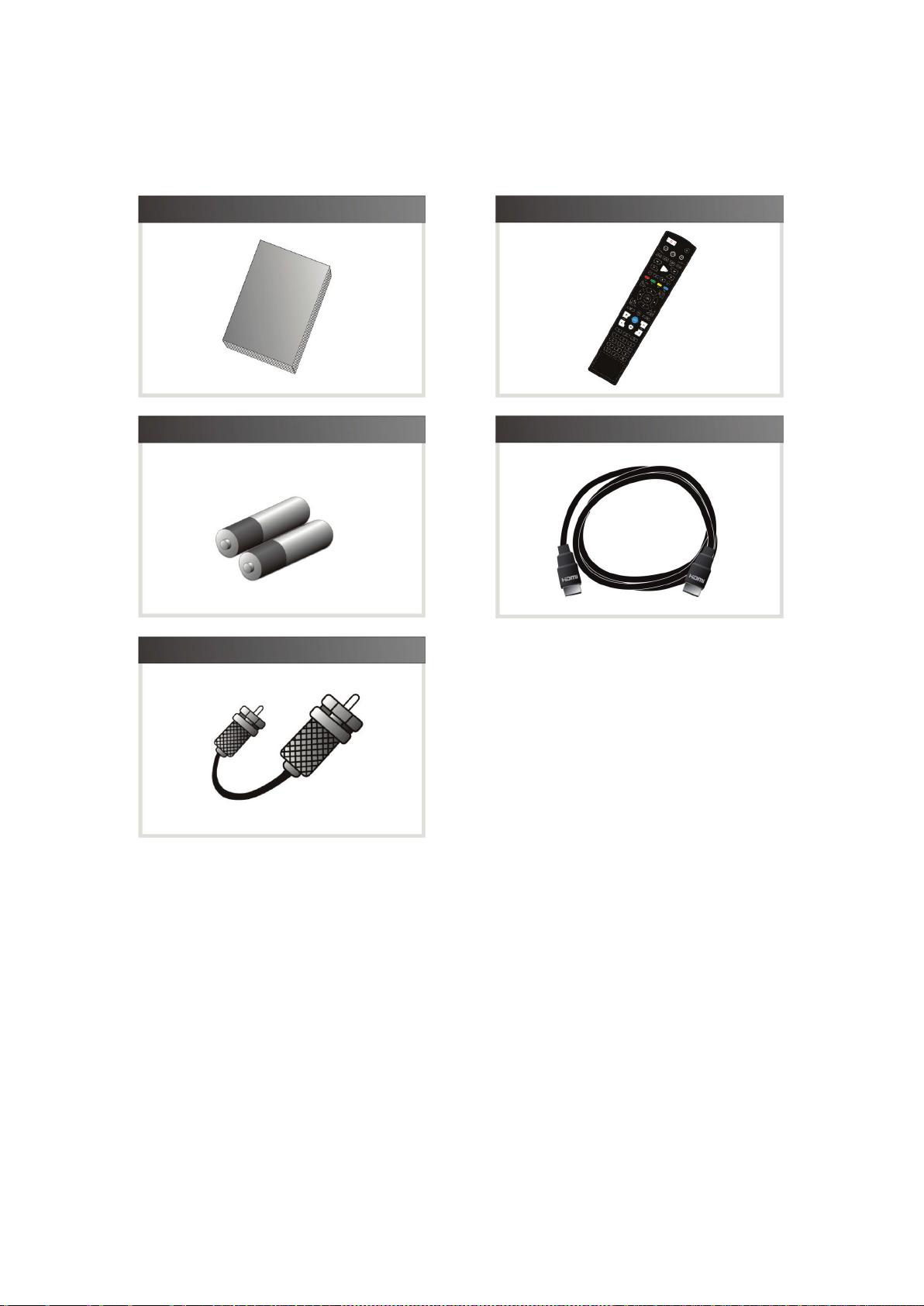
2. Accessories
User's Manual
Remote Control
AAA size Batteries X2
Loop through Cable
HDMI Cable
NOTE : If any accessories listed above are missing, contact the sales representative where you
purchased this unit.
8
Hardware Description
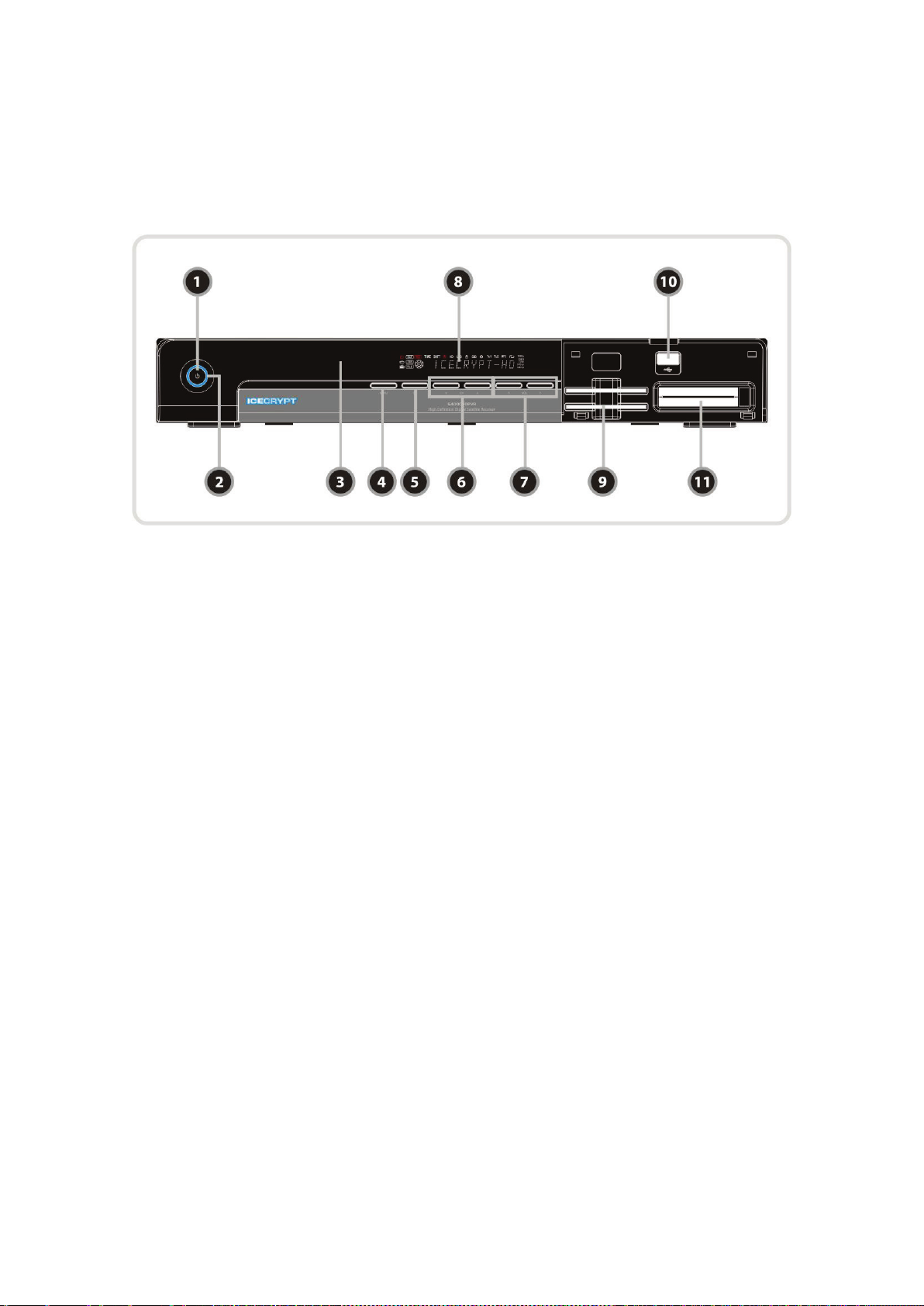
1. Front Panel Configuration
1. POWER BUTTON : Press to switch between STANDBY and POWER ON modes.
2. LED indication : The LED lights up in running mode and standby mode. You can adjust LED Lighting
Time and LED Brightness. (Main Menu >Configuration>Display Setting)
3. Remote Sensor : Receives signal from remote controller.
4. MENU Button : Press to display the main menu or to move to the previous menu.
5. OK Button : Press to display the service list in non-menu mode and to select an item or confirm
in menu mode.
6. CH Up/Down button : Press to change services in normal mode, or to move highlighted-bar in menu
mode.
7. Vol Up/Down button : Press to change audio volume in normal mode or to navigate menu in menu
mode.
8. VFD Display : The VFD consist of 12-digit letter and various icons. These letters and icon display the
current status of receiver such as service name, service information and so on.
9. SMART CARD READER : Insert smart card for encrypted service access.
10. USB(Front) : Use it when connecting to external USB storage device.
11. PCMCIA : To receive pay-tv service you need a CA-Module and a smart card from the service provider.
9
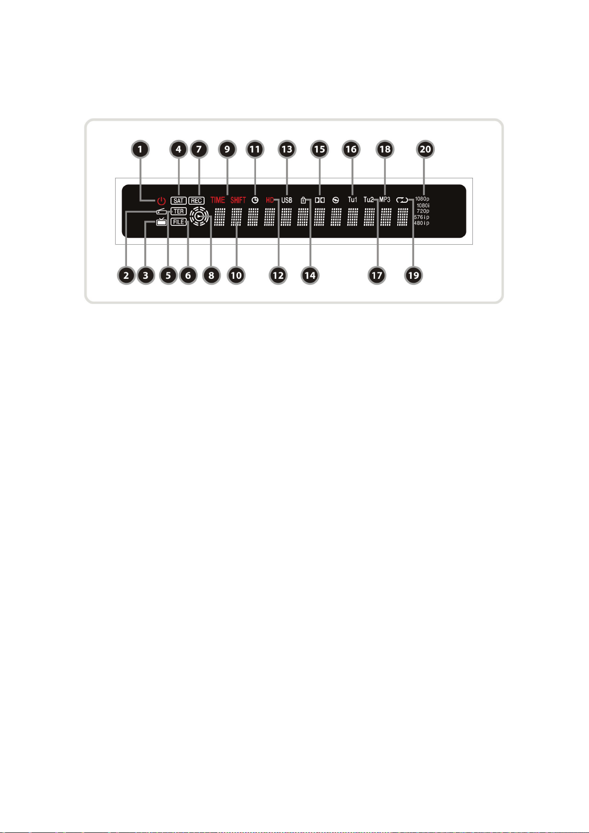
2. VFD(Vacuum Fluorescent Display)
1. Remote Indication LED : The LED lights up when a key on the Remote Controller is pressed.
2. Radio icon : The icon lights up when you change the radio service.
3. TV icon : The icon lights up when you change the TV service.
4. SAT : Satellite mode.
5. TER(Option) : Terrestrial mode.
6. FILE : Turned on when file list is displayed in the SATA HDD or USB Storage Device.
7. REC : Turned on during recording.
8. PLAY Mode : Turned on when you play the file on file list. (SATA H D D, USB Storage Device)
9. TIME SHIFT : Turned on during Time-shift.
10. Information : Display information including service name and other information.
11. TIMER : Turned on when timer is set.
12. HD : Turned on during HD service.
13. USB : Turned on during USB device working.
14. LOCK : Turned on during lock service.
15. Dolby : Turned on during Dolby service.
16. Tu1 : Turned on when using Tuner1
17. Tu2 : Turned on when using Tuner2
18. MP3 : Turned on during MP3 playback.
19. Repetition(*) : Turned on during recording repeatedly.
20. Resolution : Turned on and indicating current Resolution setting.
NOTE : (*) This icon(Repetition) will be supported later, by new s/w version by upgrading. Please
refer to your local dealer / distributor.
10
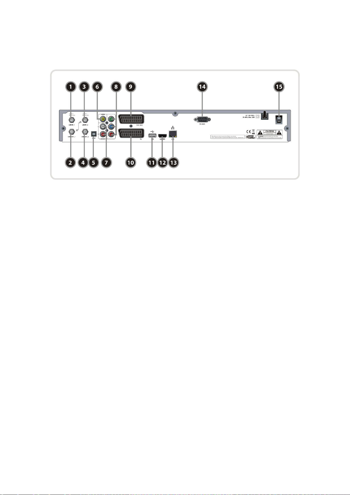
3. Rear Panel Configuration
1. LNB IN_1
Satellite broadcasting signal input socket for the first tuner. Connects a satellite antenna LNB cable.
2. LNB OUT_1
Satellite broadcasting signal output socket through the first tuner. Connects to a second tuner for
loop-through.
3. LNB IN_2 :
Satellite broadcasting signal input socket for the second tuner. Connects a satellite antenna cable or
from the first tuner LNB OUT_1 connector.
4. LNB OUT_2 :
Satellite broadcasting signal output socket through the second tuner. Connects to another STB for
loop-through.
5. SPDIF : Connects to the audio system using a S/PDIF cable. (digital audio)
6. VIDEO : Connects to the TV or VCR using a RCA cable. (Composite video output / Yellow)
7. AUDIO L/R : Connects to the TV or VCR using a RCA cable. (Stereo audio output / White, Red)
8. Component : Connects to the TV or VCR using a component cable. ( YPbPr)
9. VCR SCART : Connects to the VCR or DVD using a VCR SCART cable.
10. TV SCART : Connects to the TV input using a TV SCART cable.
11. USB : Use it when connecting to external USB storage device.
12. HDMI : Connects to the TV by using a HDMI cable for the best quality picture and audio.
13. Ethernet : Local area network port for direct computer connection.
14. RS-232C : Serial port for firmware update and data transfer.
15. A/C Switch : Power switch
11
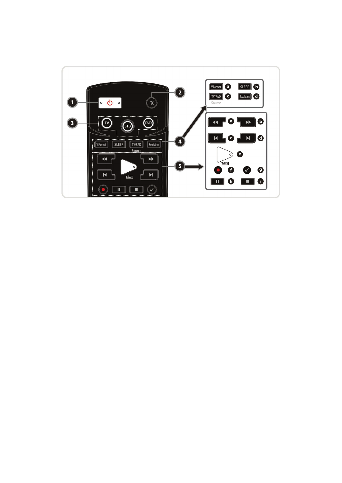
4. Remote Control Unit
1. POWER : Turns the STB On/Off.
2. MUTE : Turns the sound On/Off.
3. Universal Buttons
a. Universal TV : Change the TV Remote Controller.
b. STB : Change the STB Remote Controller.
c. Universal DVD : Change the DVD Remote Controller.
4. MODE
a. V.Format : To select the TV types.(PAL/NTSC)
b. Sleep : To adjust sleep timer.
c. TV/RADIO : Switches between TV and Radio.
d. Resolution : To select the resolution format. Each time you press the Resolution button, the
resolution changes in the following sequence: 576i > 576p > 720p > 1080i
5. Playback Control Buttons
a. Rewind : Rewinds at high speed. Each time you press this button the rewind speed is increased.
b. Fast Forward : Fasts forward at high speed. Each time you press this button the speed is increased.
c. Previous File : To play the previous MP3 file in MP3 play mode. This button is also used to jump
back to beginning of recording during a playback.
d. Next File : To play the next file. This button is also used to jump to end of recording during a
playback.
e. Play / Time shift : Display the progress bar of playback when no progress bar is displayed. Start
playback with normal speed. Return to normal speed from trick mode..
f. Recording : To start Recording.
g. Repetition (*): This key is used to play back a recording repeatedly.
h. Pause : This key is used to pause the video. Press once more to resume the video.
i. STOP : To stop time shifting, play back or recording.
NOTE : (*) This button(Repetition) will be supported later, by new s/w version by upgrading.
Please refer to your local dealer / distributor.
12
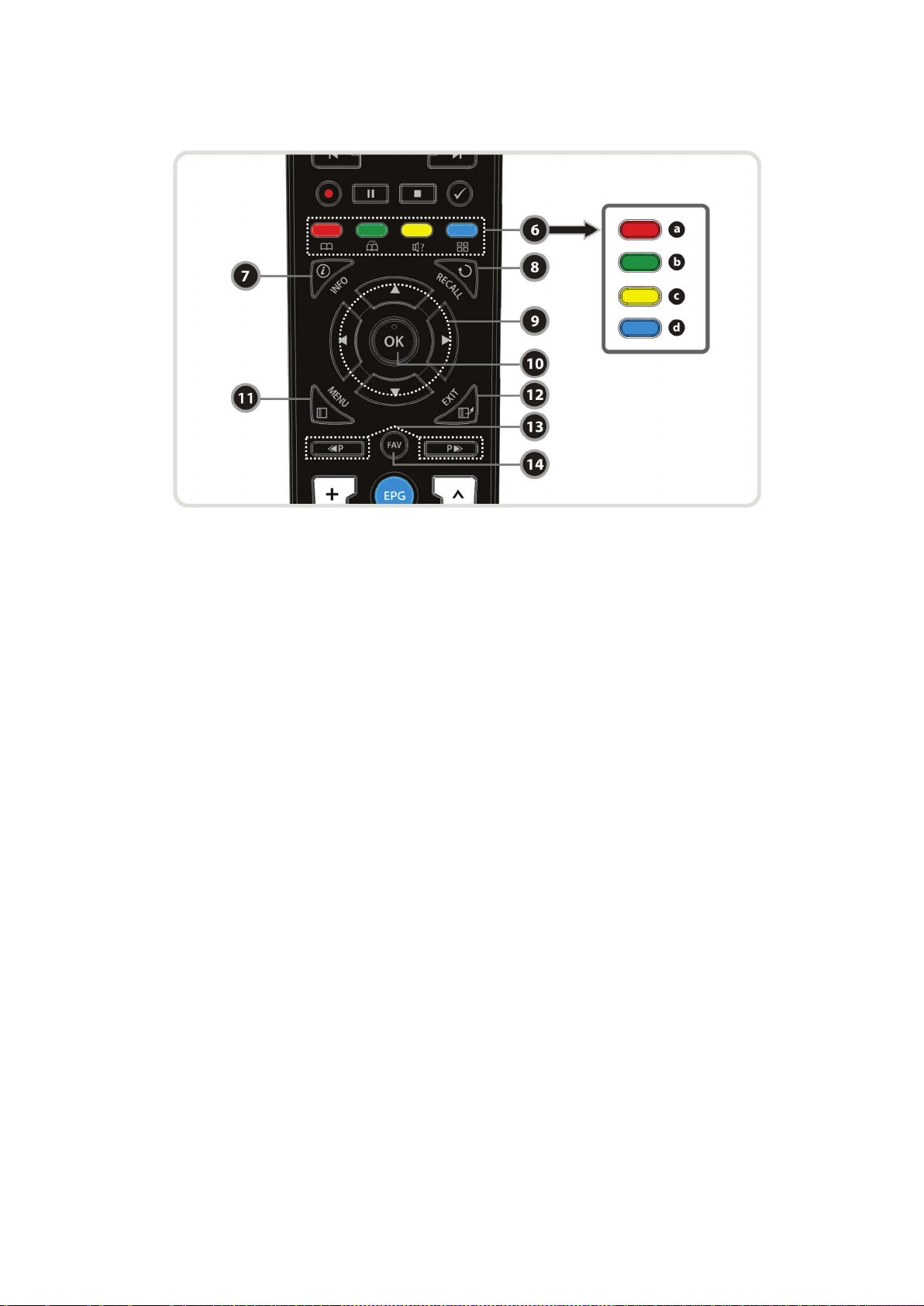
6. Color Buttons
a. RED : Used for special function in menu. RED key is used to sort lists in service list or go to previous
day search in EPG or make/delete the current position as a bookmark.
b. GREEN : Used for special function in menu. GREEN key is used to set favorites setting in service list
or go to the next bookmark position.
c. YELLOW : Used for special function in menu. YELLOW key is used to find service in service list or
change the audio track.
d. BLUE : Used for special function in menu. BLUE key is used to set service list option in service list or
display Multi-Picture.(*)
7. Information : Shows the information box of the current program. If you press one more time, a detail
information box will be shown.
8. Recall : Moves to previous service.
9. ARROW Buttons
a. Up & Down Key : To change the value of a selected item with preprogrammed values in menu.
b. Left & Right Buttons : To move the cursor left and right in menu.
10. OK or Service List : Show the service list in non-menu mode and select an item or confirm in menu
mode.
11. Menu : To enter the main menu or to move to the previous menu.
12. EXIT : Exit from the menu or pop-up window.
13. Page Up& Down : Move to the next or previous page if more than one page is available. This button
also is change the location of sub picture in PIP.
14. Favorite : To display the satellites programmed into the receiver and the favorite groups.
NOTE : (*) This Feature(Multi-Picture) will be supported later, by new s/w version by upgrading.
Please refer to your local dealer / distributor.
13
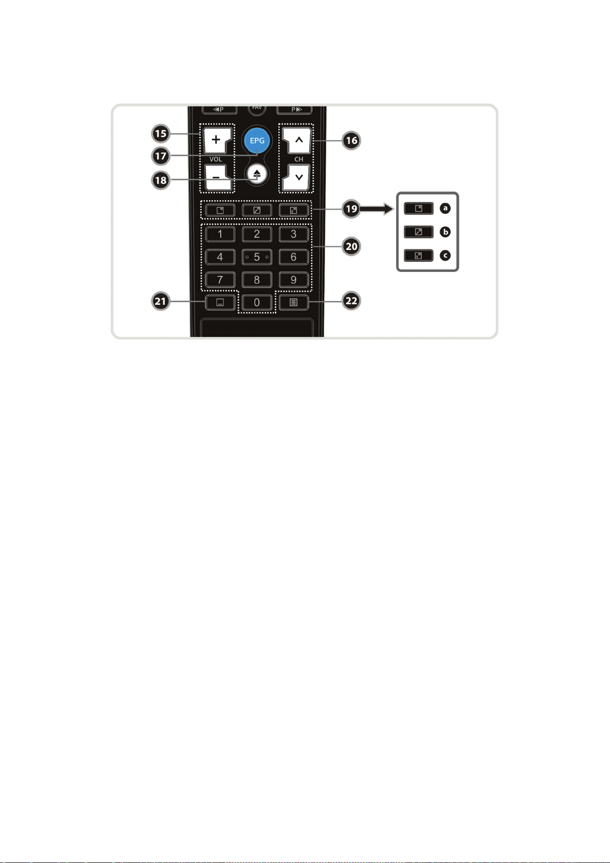
15. Volume Up & Down : To change the Volume.
16. Channel Up & Down: To change the TV or Radio service channel.
17. EPG(Electronic Program Guide) : Show the TV/Radio program guide.
18. Play List : To show the file list in the SATA HDD or USB Storage Device.
19. PIP Buttons
a. PIP(Picture in Picture) : To open the PIP window.
b. PIP Swap : Switching between main-picture and sub-picture
c. PIP(Picture in Picture) Service List : To shown the sub-picture service list.
20. Numeric : Controls the numerical operation and service numbers directly.
21. Subtitle : To show multilingual subtitle.
22. Teletext : To show the digital teletext.
14

5. Multi-Brand IR Remote Controller Setting
NOTE : When there is no input during about 10 seconds from set mode, set mode is
canceled.
1. Direct Code Entry
Step 1 : Turn on the DEVICE what you want to set up(TV / DVD / VCR)
Step 2 : Press DEVICE and OK button during about 2 seconds at the same time.
DEVICE LED will blink twice.
Step 3 : Input the 3 digit code numbers.
(Refer to ‘Code Table for Universal Remote Control Unit’ in the rear section of this manual)
DEVICE LED will blink twice and the DEVICE turns off.
If you enter a wrong DEVICE code, DEVICE will blink once
Step 4 : If your DEVICE turns off, press OK button.
DEVICE LED will blink twice.
2. Auto Code Search
Step 1 : Turn on the DEVICE what you want to set up( TV, DVD)
Step 2 : Press DEVICE and OK buttons during about 2 seconds at the same time.
DEVICE LED will blink twice.
Step 3 : Press UP or Down button within 10 seconds to enter the Search mode.
Step 4 : Press UP or Down button until the DEVICE turns off, one and one.
Step 5 : If your DEVICE turns off, press OK button.
DEVICE LED will blink twice.
3. Code No. Checking (Number Call)
Step 1 : Press DEVICE and OK buttons during about 2 seconds at the same time.
DEVICE LED will blink twice.
Step 2 : Press INFO button within 3 seconds.
LED will blink according to inputted mode number on the device.
( Case of digit '0', it blinks 10 times.)
15
Connections Diagram
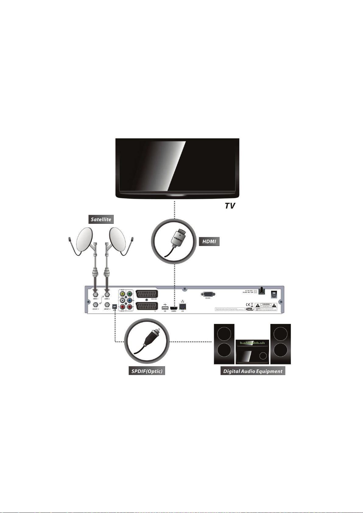
1. Receiver to TV with Digital A/V Output
Connect the satellite antenna cable to LNB IN.
Connect the HDMI Cable to the HDMI Connector of the TV.
Connect SPDIF to Digital audio input of the equipment(Digital Audio)
NOTE : Depending on the A/V equipment you own, there are various ways you can connect
the STB. To choose the best connection option, please refer to the manual of the
equipment you would like to connect to. To get High Definition playback of High
Definition content, we recommend that you connect your high definition display
with a HDMI cable. HDMI supports standard, enhanced or high-definition video
and multichannel audio in a single cable.
16
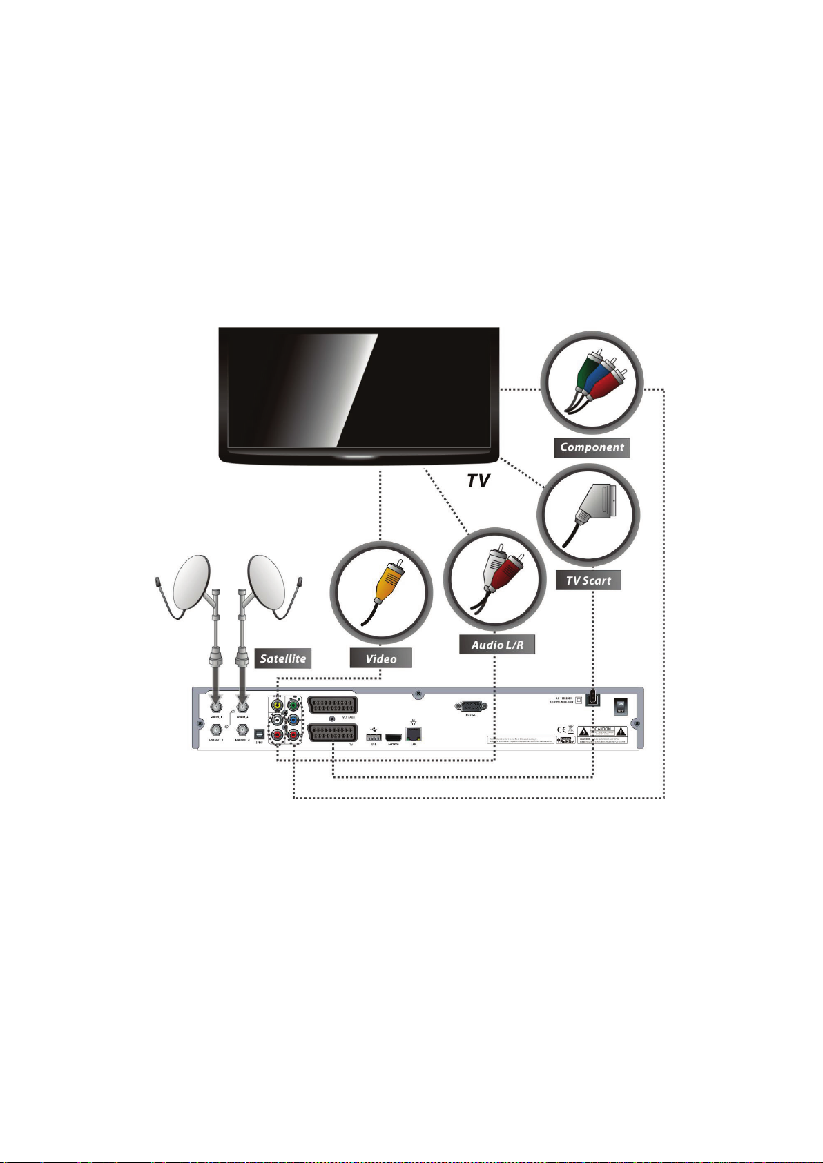
2. Receiver to TV With Analog A/V Output
Connect the satellite antenna cable to LNB IN.
Connect the TV SCART to the SCART input of the TV.
Connect the VCR SCART to the SCART input of the VCR.
Connect the Component to the Component input of the TV.
Connect the RCA to the RCA input of the TV.
NOTE : The component connection(YPbPr) is recommended for Digital TV.
The SCART cable connection is recommended for analogue TV or VCR
The composite connection(RCA cable) is recommended for analogue TV
You cannot view high definition video with the SCART and the composite video
connector.
17
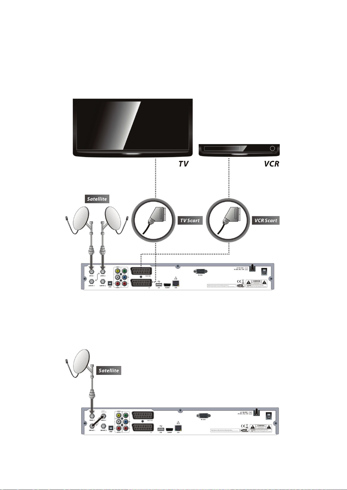
3. Receiver to TV and VCR
Connect the satellite antenna cable to LNB IN.
Connect the TV SCART to the SCART input of the TV.
Connect the VCR SCART to the SCART input of the VCR.
4. Connecting to Dish
4.1 Connecting one dish to both tuners by Loop through
18
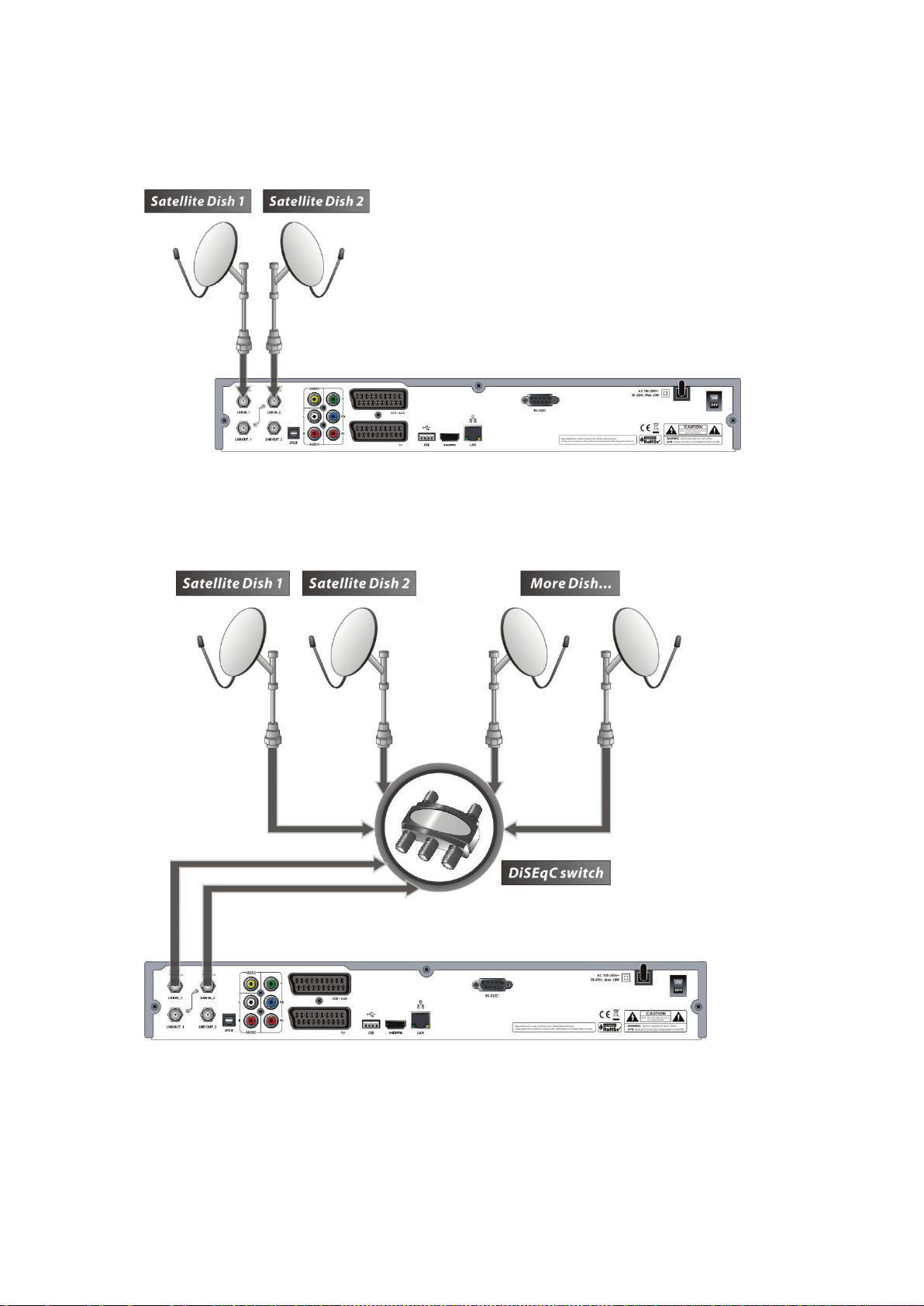
4.2 Connecting each Dish to each Tuner
4.3 Connecting Antenna cable to each Tuner using DiSEqC SW (Recommend)
19
Guide of Functions
1. Selecting a Service
To select the desired service (channel), please refer to the instructions below.
1.1 Using CH UP/DOWN buttons
You can navigate between services by pressing CH UP/DOWN buttons. Whenever you press the CH
UP(DOWN) button, current service will be changed to next/previous service. Please press CH UP or CH
DOWN button until you find the service you want to watch.
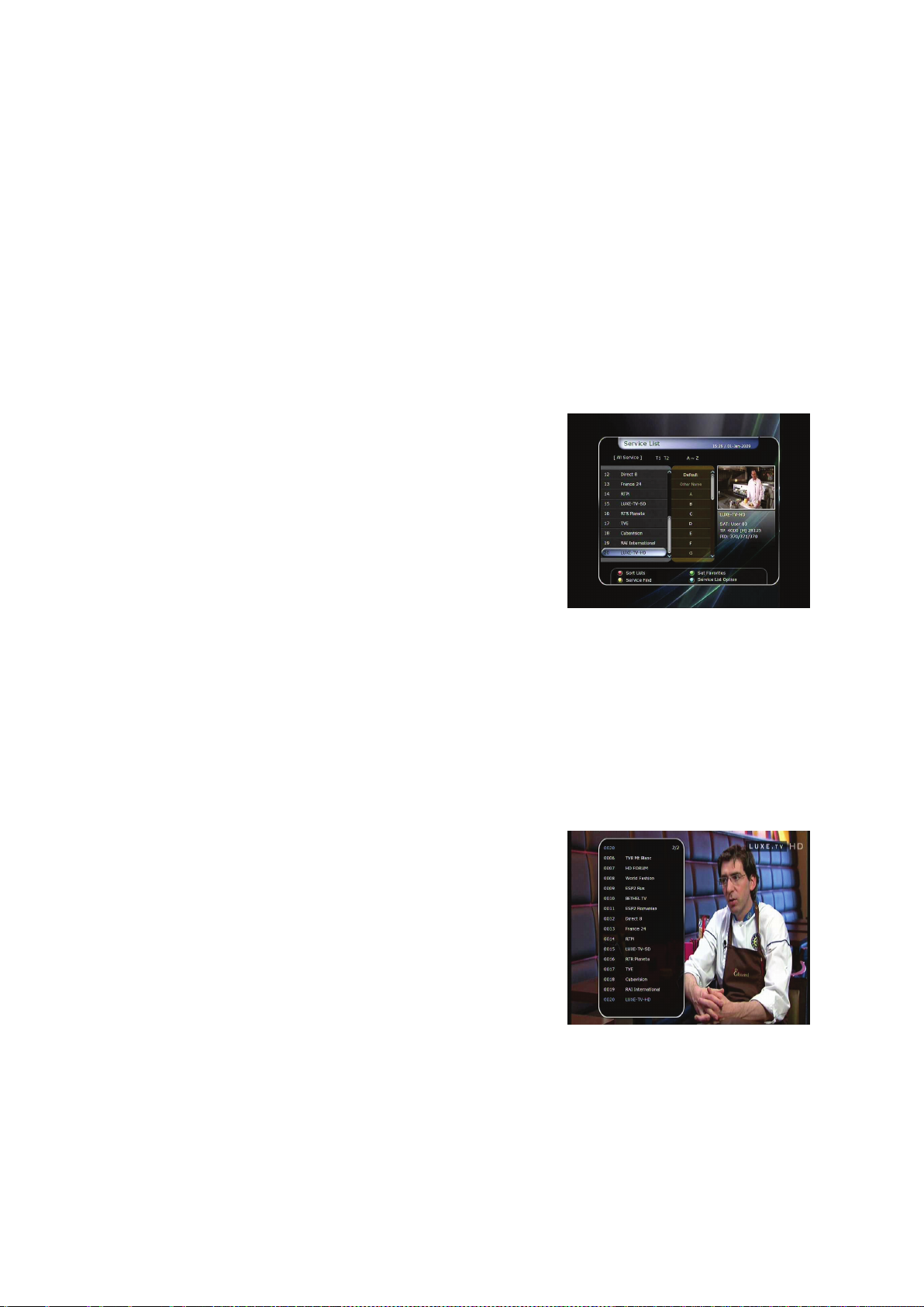
1.2 Using Service List
To select the desired service in the service list, you should firstly
display the service list by pressing the OK button.
Use the ARROW buttons to select a desired service and press
the OK button.
You can see that the service is changed in the small screen on
the top-right.
To watch that service, press the OK button once more.
To watch the previous service, press the EXIT button.
In the Service List window, you can also select additional
functions with the COLOUR buttons.
Press the RED button, and you can sort the services by the Alphabet, Transponder(TP), Group, Tuner
and CAS (Conditional Access System).
Press the GREEN button, and you can add the services to one of 10 Favorite Lists.
Press the YELLOW button, and you can search & find the service via a virtual keyboard.
Press the BLUE button, and you can adjust service list option.
NOTE : If you connect the tuner with a loop-through, you cannot use the sort list option.
1.3 Using Instant Service List
If you press NUMERIC buttons or UP/DOWN ARROW button,
instant service list will be displayed.
Select the desired service by using the ARROW button, and
press OK button to watch.
You can also enter the service number directly by using the
NUMERIC button.
20
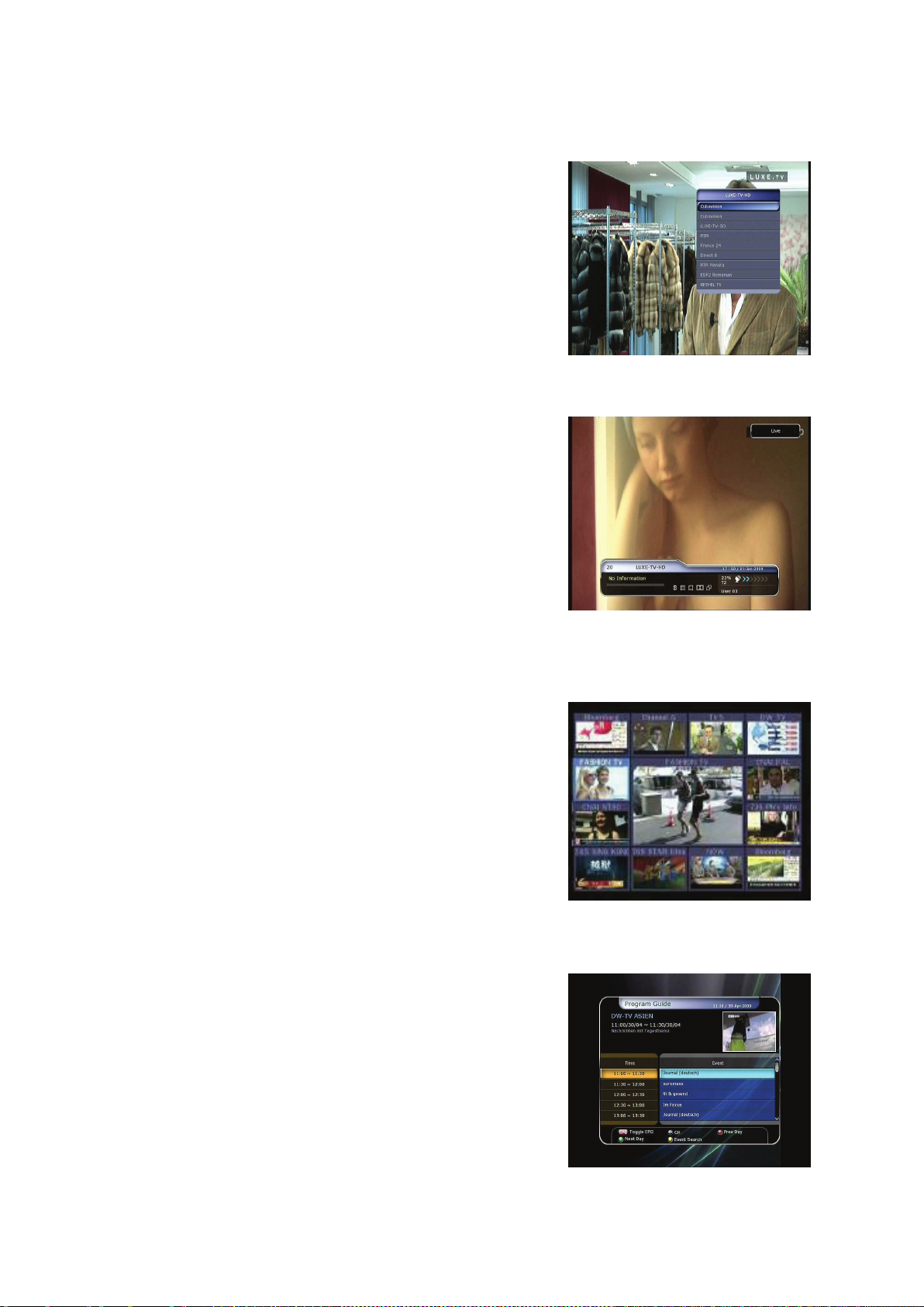
1.4 Using Recent Service List
To return to the previous service that you were watching,
press RECALL button.
To display recent service list, press the RECALL button and
hold for a few seconds.
To chose the service from the recent service list, use the
ARROW button to select, then press the OK button.
Press EXIT button to exit from the recent service list.
2. Information Window
If you want to view the information of the current service that you
are watching, press INFO button. Then the Information window
will be displayed.
This Information window is automatically displayed when
changing between the services. This window contains useful
information such as service number, service name, scrambled
types of service, teletext, subtitle, Audio indication for Dolby
Digital, Time duration of the service and so on.
By pressing INFO button once again, you can get more detailed
information about the service.
3. Multi-Picture Display. (*)
Press the BLUE button to display multiple pictures and use the
RED button to select the display options for 9 or 12 multiple
pictures.
NOTE : (*) This feature will be supported later, by new s/w
version by upgrading. Please refer to your local
dealer / distributor.
4. Electronic Program Guide (EPG)
Electronic Program Guide (EPG) allows you to see program
schedule and program information from the service which
includes this data as part of their transmission. Multiple services
will be shown with a time line of programming events. The EPG
supplies additional information of channel service, such as
program listings, start/end times and detailed information about
the program listings for all available services.
The availability and details of information of these program
details can be varied, depending on the particular broadcasters,
individual services.
21

Press the EPG button, then the EPG menu will be displayed.
Use the ARROW buttons to move to other services or to see previous/next guide.
Press the EPG button once to view full EPG with multi service list, and press it twice to view the
additional EPG information of a specific channel service. Keep pressing the EPG button to toggle
between the full and detailed menus of EPG.
Press the GREEN button to view next day EPG and the RED button to view EPG for a previous day.
Select the program by using the ARROW buttons then set the event timer by pressing OK.
You can schedule a recording with the EPG menu as follows.
- Press RECORD button to schedule the event. This schedule can be checked in the menu of Timer
Settings, in the System tool menu.
- To cancel the schedule of the recording, press the OK button for the appointed event.
- To edit the schedule of the recording, press the RECORD button for the appointed event.
5. Favorite Group
Select the FAV (Favorite) to view all favorite ten groups such as
sports, movie, drama, satellite group and so on. Scroll through the
various favorite group using the ARROW buttons, and select the
desired favorite group by pressing OK.
6. Volume Control
To adjust the audio volume, press the VOL UP/ DOWN
buttons.
Audio volume control bar will be displayed at the top of the
screen and disappear after 4 seconds.
When necessary, press the MUTE button to turn on/off the
audio sound.
NOTE : The mute function remains set while you change
services.
7. Pause
The PAUSE button is used to freeze the video. Press PAUSE button once more to resume the video.
8. Subtitle
You can select the language for a Subtitle, if the program provides subtitle information.
Press the SUBTITLE button on your remote control unit.
Select the desired subtitle language then press OK button.
22

The subtitle will be displayed in the selected language at the bottom of the screen.
To turn OFF the subtitle from the screen, Select ‘Off’ from the subtitle language list.
NOTE : When program does not provide subtitle information, SUBTITLE button is not active.
9. Audio Track
User can select the audio language list by pressing the
AUDIO(YELLOW) button. Use the ARROW buttons to choose
the preferred audio track from the list, then press OK to change.
Multiple use of the YELLOW button toggles between additional
menus
10. Teletext
When the TELETEXT icon on INFO Banner is appeared (Activated), Press the TELETEXT button to view
the teletext information.
11. PIP (Picture in Picture)
When you press the PIP button, a sub picture screen will appear on the main screen view.
If you press the PIP button one more time, the primary picture and the sub picture will appear
together side-by-side with the same size. The picture of the left side is the primary and the picture on
the right side is sub. If you press the PIP button one more time, the sub picture will disappear.
23

In the PIP mode, you can change primary and sub with the PIP SWAP button.
If you press the PAGE UP/DOWN button, the location of the sub picture is changed.
If you press the PIP SERVICE LIST button, you can see the list
of services of sub picture.
You can change the service of the sub picture from the service
list shown.
NOTE : Changing services of sub the picture could be
limited by the condition of the tuner connection or
a recording event ongoing.
24

PVR (Personal Video Recorder) Function
1. Recording
You can select a recording storage device with the following sequence :
Menu > Configuration > Recording Option > Record Device.
Default is set to ‘Hard Disk’.
1.1 Recording methods
There are 3 type recording methods.
(Instant Recording / Time Scheduled Recording / Event Scheduled Recording).
Instant Recording :
At anytime, you may press the RECORD button to start your
recording instantly.
Time Scheduled Recording :
- In Timer Settings menu, you may set the time & program to
record your desired service program.
(Main Menu > System Tools > Timer Settings)
- Press the GREEN button to activate the new timer edit screen.
- In the Timer Edit screen, you may choose start date/time,
duration, service, mode, type (Recording/Play), Tuner
(Auto/1/2) then simply press the Yes button to schedule
your recording event. Please note that the minimum
offset time of 3 minutes is required from the Start time &
current time for appropriate recording process to take place.
25

Event Scheduled Recording via EPG :
In the EPG menu screen, you can choose the event you wish to
schedule or record.
- While watching the LIVE TV screen, press the EPG button to
access the EPG menu screen.
- Go to the event which you wish to view at the time
indicated on the EPG schedule, then press OK. The event
will be scheduled with the BLUE play icon. This BLUE play
icon means that you want to just watch the event at the
scheduled time.
- Press the OK button one more time, then the event will be
scheduled with the RED dot icon. This RED dot icon means
that you want to record the event at the scheduled time.
- When you set an event for scheduled recording via the EPG
menu. It automatically sets a Timer Event in the Main
Menu > System Tools > Timer Settings.
26

1.2 Recording Edit
Press the REC button while recording to see the recording message window.
Pause : Select Pause Recording then press OK to pause the current recording process.
Duration : Set recording duration. Press LEFT/RIGHT ARROW button to change recording duration.
Stop Position :
Set the finishing time of recording.
- End of current event : finish recording at the end of
current event
- End of next event : finish recording at the end of next
event.
- Not Available : EPG is not available.
Record Slot : When you are recording 2 services, you can set
Primary / Secondary with Left/Right ARROW button. Press
OK button to go to the recording service.
1.3 Long Time recording
During lengthy time recording processes of 4GB(Giga Byte) or more, additional files may be created per
every 4GB. (For example; aaa.ts, aaa.ts1, aaa.ts2… and so on).
You must remember not to erase any of the duplicated file. These files are only able to be viewed with
your PC not with the receiver (STB).
1.4 Pause during recording
When the PAUSE button is pressed during recording, only the
live video is paused, but recording is continued at the selected
recording device.
(Menu > Configuration > Recording Option > Record Device)
Press PAUSE button once again and event will resume from
the pause time.
27

During recording, press the PLAY/TIMESHIFT button to show
the Play bar screen.
While the Play bar is shown on your screen, you may use the
LEFT/RIGHT ARROW button to move (forward & backward)
freely within recorded time.
If you press the STOP button, it will go to LIVE and you may press PREV FILE button to view the
recorded file from the beginning.
When recording 2 services at the same time, Press the STOP
button to see a message window of current recording status /
information.
If you select one of the 2 recordings and press the OK button,
that recording service will be stopped.
If you press the STOP button during recording 1 service, the
recording will be stopped.
NOTE : Dual Recording
STB can record up to two different services simultaneously. Time shifting is also a
recording, so Time shifting will be possible on one of the two recordings during dual
recording.
28

2. Time Shifting
You can select a storage device for a temporary file of the Time
shifting with the following sequence:
Menu > Configuration > Recording Option > TimeShift Device.
Default storage device is set to ‘Hard Disk(SATA)’
If pressing the PAUSE button during Time shift, the live video
is paused but the temporary recording for time shift is
continued at the selected storage device.
Press the PAUSE button once again, then the event will
resume from the paused time.
While watching live TV, press the PLAY/TIMESHIFT button to
show the play bar on your screen.
When the play bar is displayed on your screen, you may use
the LEFT/RIGHT ARROW buttons to move freely through the
recorded times bar.
If you press the STOP button while time-shifting, the screen
will be turned to a live TV channel. You can also use PREV FILE
button to move to a start location of the Time-shifted file.
29

3. Playback (Play List)
You can playback many files with the Playlist which you access by the PL AY LI ST button.
In the Playlist, you can check and playback recorded files, multimedia movie files, MP3 music files, and
image files. With the LEFT/RIGHT ARROW button, go to the Recorded Files, Imported Files, Music and
Photo category and check & for playback files in each category. Press the RIGHT ARROW button once to
go to Imported Files, press the RIGHT ARROW button one more time to go to the Music menu and press
the RIGHT ARROW button one more time to go to the Photo menu.
3.1 Recorded Files
To enter Recorded Files menu, press the PLAY LIST button.
Locate the recorded file(s) you wish to play with the
UP/DOWN button and press the OK button to playback the
recorded file(s).
To choose a particular selection of files, select a desired file
and press the RED button. Press the OK button to begin the
selected files.
Select Device : Press PLAYLIST button one more time in the
Playlist mode to see “Select Device” window, and select the
device which has the file you want to play.
NOTE : “Select Device” window shows devices which are
currently connected to the STB.
Sorting : If you press the YELLOW button, you can sort the
files by Time / Name / Size.
File Option : If you press the BLUE button, you can delete or
move files, make a folder, rename in File Option. You can
select multiple files together and delete or move all of them at
once.
30

3.2 Imported Files
If you press RIGHT ARROW button in Recorded Files, you can
go to Imported File menu.
Locate the file(s) you wish to play with the UP/DOWN button
and press the OK button to enjoy the movie.
To choose a particular selection of files, select a desired file
and press the RED button. Press the OK button to begin the
selected files.
You can use the same ‘Select Device’, ‘Sorting’ and ‘File Option’
features as in the Recorded Files.
3.3 Music
If you press the RIGHT ARROW button in Imported Files, you
can go to Music menu.
If you press the RECALL button, you can enjoy music with
Shuffle playback and repeat.
You can use the same ‘Select Device’, ‘Sorting’ and ‘File Option’
features as in the Recorded Files.
3.4 Photo
If you press the RIGHT ARROW button in Music, you can go to
the Image Photo menu.
If you press the RED button or OK button, you can start the
slide show of image files. Press the EXIT button to stop slide
show.
If you press the GREEN button, you can adjust the Slide Time,
Repetition, Title, Down-scale.
You can use the same ‘Select Device’, ‘Sorting’ and ‘File
Option’ features as in the Recorded Files.
4. Bookmark
When the Play bar is displayed, you may move to desired time
and book mark it by pressing the RED button. Bookmark(s)
are indicated with a Green line on the play bar. Also, you may
press the RED button to activate the play bar to mark your
bookmark(s).
31

When the play bar is on, user can move / jump between the bookmarks by pressing the GREEN button.
If you wish to delete any Bookmarks, go to that bookmark by
pressing the GREEN button, then press the RED button to
delete the current bookmarks.
5. Trick mode
The user can change the speed of a fast forward play with
FF(Fast Forward) button. Press FF button to change the
speed to x2, x3, x4, and x5. If you once again press FF button
in its x5 mode, it returns to normal(x1) speed play.
You can also change rewind speed with the REWIND button.
Press REWIND button to change the speed to x2, x3, x4, and
x5. If you press the REWIND button again in it is at the x5
mode, it returns to normal speed.
You may press the PAUSE button at any time to pause a pre-
recorded event. Press the PAUSE button once again to resume play of the recorded event.
32

Menu Map
System Tools
Main Menu
1. Storage Manager
2. Timer Settings
3. Service List Manager
4. Data Transfer
Configuration
Installation
1. Recording Option
2. Parental Control
3. Display Setting
4. Time Setting
5. Language Setting
6. A/V Output Setting
1. Dish Setting
2. Positioner Setting
3. Service Search
4. Network Setting
5. System Recovery
6. System Information
1. Calculator
2. Calendar
3. CAS
Utilities
33

Main Menu of Guide
To display the menu, press the MENU button at any time. You can
select the sub menus by using the ARROW buttons.
The selected sub menu becomes highlighted. After selecting
(highlighting) the sub menu you want to access, press the OK
button. If you want to return to the previous menu, press the
MENU button. And if you want to exit from the menu, press the
EXIT button.
1. System Tools
1.1 Storage Manager
The items in this menu allow you to access and control the storage devices that you want.
Current Device : Select the storage device you want to access
with the ARROW/OK buttons.
Status : You can see the information of current connected
devices, such as ‘Mounted’, ‘Not Available’
File System : It shows the file system of the current device.
You can also select desired file system that you want when
you format the device.
NOTE : You must select FAT32 file system, if you want to
access the USB storage devices in Windows
Total : Displays total size of current device.
Free : Displays free size of current device.
Format : If you press the OK button to format current device, the device will be formatted with above
file system.
NOTE : When file system is ‘Unknown’, the device will be formatted with ‘Journaled’.
Play List : Press OK button to move to ‘Play List’ menu directly.
1.2 Timer Settings
Insert a new timer entry or modify an existing timer entry.
To add new timer entry : Press the GREEN button. Timer Edit
window will popup. You can set the specific start date, time,
duration and service for its reservation. And you can choose
one of Timer Modes as 'Once' or 'Daily' or 'Weekly'. You can
choose timer operation type as ‘Recording’ or just to 'Play'.
- If you choose 'Recording', it will start recording at that time.
- If you choose 'Play', it will change and tune to the service
that you wish to watch.
To modify existing timer entry : Choose the timer entry
which you wish to modify and press the OK button.
To delete an existing timer entry : Choose the timer entry that you want to delete and press the RED
button.
NOTE : If you reserve one or more event through the EPG menu, the reserved event(s) will be
added to Timer Settings automatically.
34

1.3 Service List Manager
Service List Manager menu will appear when you press the OK button.
You can select Edit Mode by pressing the YELLOW button.
Lock Services : All service lists will be shown on the left side of
the window, the middle will show the list of service to be
locked. By using the ARROW and OK buttons, you may move
the chosen service to the middle window to lock that service.
Services can also be moved back from the middle to the left
side to un-lock them.
Move Services : All service lists will be shown on left side of
the window, services to be moved will be shown on the
middle window. Move the service to the middle window by
using the ARROW and OK buttons, then the middle window
service will be moved to a specified location when the desired
location is selected from the left window.
Delete Services : All service lists will be shown on left side of
the window. By using the ARROW and OK buttons you may
select services to be deleted by placing them in the middle
window. The press the GREEN button to delete the selected
services.
Skip Services : All services will be shown on left side of the
window, the middle window will only show the services that
are chosen to be skipped. By using the ARROW and OK
buttons you may move the selected services from the left to
middle window to skip them.
35

Set Favorite Services : Use the ARROW and OK buttons to
select your desired favorite group. Once, favorite group is
chosen, the left side window will show all service lists and the
middle window will only show the selected services of the
favorite group selected. By using the ARROW and OK buttons,
you may ADD the desired services to a favorite group or
DELETE any from the favorite group. The name of the favorite
group can be edited by pressing the GREEN button.
Edit Services : All service names will be shown on the left side
of the window. Move the highlighted bar to the service where
you want to edit its name and press the OK button. Then you
will see the virtual keyboard. Using the ARROW and OK
buttons, you can edit the name of the service with the
keyboard.
1.4 Data Transfer
When the data transfer task is in process, the Front USB slot is set to a default device slot. But, if no
USB device is connected on a front USB slot, then the Rear USB slot is set as a device to be used for the
data transfer process.
NOTE : If no USB device is connected on either two (Front & Rear) USB slots, then a Menu item
will not be available.
Transfer all System data to USB storage : If you want to
transfer and use BOTH of the current system parameters and
service data in the future, this menu will allow you to store all
data to your USB device. Press OK button to store all current
data to an external USB storage.
Transfer Service data to USB storage : If you want to transfer
and use ONLY the service data in the future, this menu allows
you to store current service data. Press the OK button to store
the current service data to your external USB storage. The
service data can also be viewed and edited on a PC with an
appropriate editor (DrEdit) for the file saved.
Data download from USB storage device : This menu allows you to download the saved data from
the external USB storage to your STB. Press OK button to download data.
36

2. Configuration
2.1 Recording Option
Confirmation message when ‘stopping’ your Recording process :
- Set 'On' : When you press the STOP button while recording, then a confirmation window is
displayed.
- Set 'Off' : When you press the STOP button while recording, the STB will stop the recording process
immediately / instantly with no extra confirmation message.
Extra Event Recording :
You can add an extra recording time(1 Min/2 Min/3 Min/4 Min/5 Min/10 Min/15 Min/off ) to
scheduled recording events.
If you set an extra recording time by using the ARROW and OK buttons, the scheduled recording
event will have a ‘Start’ and ‘End’ time of additional recording time added to the basic event..
This option only works for real time events. But, when you schedule a service recording in the Timer
Settings menu, this option has no affect.
Time-Shift :
You can adjust the time-shift in 30 minute intervals.
(30 Min/60 Min/90 Min/120 Min)
When selected, time shifting function works automatically up
to the limit of time that you set, as long as the Time-Shift
storage device has enough memory space.
If you set this option to ‘OFF’ status, then the time shifting
function never works.
Time-Shift Device :
You can select the Time-Shift Device you want, such as Hard Disk / USB1(Front) / USB2(Rear).
Record Device :
You can also set a Recording Device which you want to use, such as the Hard Disk / USB1(Front) /
USB2(Rear). Recorded files are stored in the device you set.
2.2 Parental Control
User’s access rights to a service and programs are controlled by
a 4-digit secret code that is defined by the user. Whenever you
attempt to access the parental control menu, a pop-up
window will ask you to input a PIN code. (If necessary, you can
change it.)
NOTE : The default PIN code is ‘0000’
Censorship : Set the parental guidance rating of highlighted
censorship classification. The parental level is given as an agebased number.
Change Pin code : To change your PIN code, input the new
PIN code using the NUMERICAL buttons. To verify the new
PIN code, input the new PIN code again.
System : Set the access rights to the System menu.
Installation : Set the access rights to the Installation menu.
Configuration :
Edit Service : Set the access rights to the Edit menu.
Set the access rights to the Configuration menu.
37

2.3 Display Setting
Info Box position : Set a position of the information window.
Info Box Display Time : Set the time duration of the
information window being displayed on the screen after
changing services.
Volume Bar Display Time : Set the time duration of the
volume bar being displayed on the screen after changing
audio volumes.
EPG Time Range : You can set the time range in hours which
is displayed for a program in the EPG window.
Zapping Mode : You can set the zapping mode as follows (zapping mode is when changing services).
- Black screen : Display a black screen when changing between services.
- Freeze : Display the last still picture when changing services.
Front Display Scroll : You can set how the VFD Display Scrolls.
- On : Continually scroll the service name, if the letters of the service name is over 12 characters.
- Off : Scroll service name once, if the letters of the service name is over 12 characters.
Front LED Lighting Time : You can adjust the lighting time of the front LED.
Front LED Brightness : You can adjust brightness of the front LED with 4 steps. By setting ‘off’ this
option, will turn off the front LED lighting.
2.4 Time Setting
Time Setting : To set the current time, you can use two modes; Auto or Manual.
- Auto Time Setting
Local Offset : Enter the offset value by using the
standardized information of current service area.
Daylight Saving : If you want to apply daylight saving,
select the counter by using the ARROW buttons.
- Manual Time Setting
Date : Enter the calendar date by using ARROW buttons
then press the OK button to finish.
Time : Enter the time by using the NUMERIC buttons.
Clock Mode : Select the type of clock display(12 Hours or 24
Hours) using ARROW buttons.
Wake Up Mode : Enter the time for the receiver to automatically power ON. And you can choose one
of Wake Up Mode as ‘off’ or ‘Once’ or ‘Daily’ or ‘Weekly’.
- Wake Up Date : Select the date when the STB is turn on. Press the OK button to display calendar.
- Wake Up Days : Select a day of the week when the STB is turn on.
- Wake Up Time : Enter the wake up time of the STB using the NUMERIC buttons.
- Wake Up Service : Select the service when the STB is turn on. Press the OK button to display the
service list.
Sleep Mode : Enter the time for the receiver to automatically switch OFF and go to standby mode.
And you can choose one of the Wake Up Mode as 'off' or 'Once' or 'Daily' or 'Weekly'.
- Sleep Date : Select the date when the STB is turn off. Press the OK button to display the calendar.
- Sleep Days : Select a day of the week when STB is turn off.
- Sleep Time : Enter the turn-off time of the STB using the NUMERIC buttons.
2.5 Language Setting
Menu Language : Select the desired menu language by using the ARROW buttons.
NOTE : The menu and operation languages can be changed depending on the country sold.
Available languages are subject to change without prior notice.
38

Audio Language : Select the default language for the audio
when changing services. If no other language is provided,
then the default language of current will be automatically
selected.
Subtitle Language : Select the default language for subtitle
when changing service.
2.6 A/V Output Setting
TV Type : Select the TV types.(PAL/NTSC/Auto) In Auto mode,
the STB is automatically selected to NTSC or PAL accordingly
to the service played.
TV Aspect Ratio : Select the aspect ratio of TV which is
connected to the STB.(4:3/16:9). This menu must be set prior to
selecting the Display Format function.
Display Resolution : Select the Display Resolution of the
screen by using ARROW or OK button. You can also change
the resolution with Resolution button in the remote. Each
time you press the Resolution button, the resolution changes
in the following sequence: 576i > 576p > 720p > 1080i
NOTE : Please note that your TV may not show a picture depending on the Display Resolution set
by your STB as well as if set to PAL when NTSC is required or vice versa. If you set the
Display Resolution as SD(576i), your TV cannot display anything when the TV is
connected to the Component Video(YPbPr). If you set the Display Resolution as HD(more
than 576p), your TV cannot display anything when the TV is connected to the SCART or
Composite Vi deo output of the STB. In case of HDMI, your TV can display a picture for
all of the resolution settings of the STB. But it is also possible that your TV may not
display a picture with 576i, because some HDTV’s does not support 576i.
Display Format :
In case of a 4:3 ratio TV set, you can select Letter Box or Pan&Scan. In case of a 16:9 ratio TV set, you
can select Pillar Box or Full Screen.
- 16:9 Display format on 4:3 TV set
Letter Box : You can see the full screen of 16:9, but top and bottom edges of your TV screen
display black horizontal Pillars.
Pan&Scan : The picture is displayed in full on your 4:3 TV screen, but left and right sides of the
original picture cannot be displayed.
- 4:3 Display format on 16:9 TV set
Pillar Box : You can see the full screen of 4:3, but left and right sides of your TV screen display black
vertical Pillars. 4:3
Full Screen : The picture is displayed in full on your 16:9 TV screen, but left and right sides of the
original picture is displayed with widening of the screen from left and right. Because of the artificial
widening, the TV picture will be distorted.
Video Output Mode : According to Display Resolution, you can select the Video Output Mode.
- In case of More than 576p(HD) : The ‘RGB’ output will be disabled automatically. You can select
Video Output Mode (CVBS, YPbPr, YC).
- In case of 576i(SD) : The ‘YPbPr’ output will be disabled automatically. You can select Video Output
Mode (CVBS, RGB, YC).
Sound Mode : Set the audio mode output among the RCA jack, optical SPDIF and
HDMI.(Stereo/Mono/Left/Right).
39

3. Installation
3.1 Dish Setting
Select the satellite/antenna and LNB settings for service search.
The values that are set in this menu will be available for selection
in other service searching menus.
Satellite : Select the satellite which you want to do a search
for.
- Press the LEFT/RIGHT ARROW button to select the satellite.
- If you press the OK button, the entire satellite list will be
displayed.
- Select the desired satellite name to search.
- If the desired satellite name is not listed then select User
Defined.
Tuner Connection : You can set connection type between Tuner and LNB.
- Separate : Set the connection type option to ‘Separate’, if each of the tuners are connected to
different LNBs (LNB IN_1 / LNB IN_2) individually / independently.
This Separate connection is used, when each two tuners are connected to different LNBs. Due the
independent & separate connections between two Tuners & LNBs, user can watch all the services
scanned by one tuner(1), while the other tuner(2) is set for recording at the same time.
- Loop-Through : Set the connection type option to ‘Loop-Through’, if you have connected the LNB
OUT_1 and LNB IN_2 with a loop-through cable. In this case, you would have some limitations in
using some features such as dual recording.
This connection is used when the Tuner(1) is connected with LNB output, and the Loop-through
output of the Tuner(1) is connected with input of the Tuner(2). This is the way to use & activate both
tuners when you have only 1 LNB with your dish antenna. However, this will limit the possible
tuning range (Satellite & Polarization) of the 2
recording process (because the input signal of 2
tuner is tuned to).
NOTE : User should make the appropriate connection by choosing the right tuner connections
between the Loop-Through and Separate connections. Due to the difference of these
two connections, wrong LNB and Tuner connection may cause the loss of signal reception.
We strongly recommend the use of professional service personnel to make this installation
and connection if your knowledge is limited.
Tuner : Select the tuner which you want to set (Tuner 1/ Tuner 2). If you set ‘Loop-Through’ on the
menu(Installation-Dish Setting-Tuner Connection), this menu(Tuner) will be disabled automatically.
Frequency : Select the satellite frequency which you want to use for checking the signal.
LNB Power : Select the LNB power on or off.
LNB Type : Select the LNB type.
LNB Frequency : Select the local oscillator (L.O.). frequency that is specified for the LNB used..
- Use the LEFT/RIGHT ARROW buttons to select the LNB frequency.
- If the required LNB frequency is not listed, then enter the frequency manually using the NUMERIC
buttons.
- When you select Universal LNB type, both 9750 and 10600 are supported at the same time. And
then the LNB 22KHz setting is disabled.
LNB 22KHz : When you use a separate coax 22 KHz tone switch box, make the 22 KHz tone switch
enabled or disabled to select the input you desire of the tone switch.
DiSEqC Switch : If you use DiSEqC 1.0 or DiSEqC 1.1 switch, select one of the DiSEqC inputs.
Service Search : Press the OK button to move to the Search Menu
nd
tuner, while the 1st tuner is being used for its
nd
tuner is dependent of the signal which the 1st
40

3.2 Positioner Setting
Satellite : Select the satellite which you want to search for the
Service.
- Press the LEFT/RIGHT ARROW button to select the satellite.
- If you press the OK button, a complete satellite list will be
displayed.
- Select the wanted satellite name.
- If the desired satellite name is not listed then select User
Defined.
Tuner : Select tuner that you want to set (Tuner 1/ Tuner 2). If you have set ‘Loop-Through’ in the
menu(Installation-Dish Setting-Tuner Connection), this menu(Tuner) will be automatically disabled.
Frequency : Select the satellite frequency you want to use to check for a signal.
Positioner : Select the positioner.
- None : (No Positioner)
- Using DiSEqC 1.2 :
Move : To move the dish, press LEFT/RIGHT button.
Fine Move : To move the dish in smaller steps, press the
LEFT/RIGHT ARROW button.
Step : Set to positioner moving steps as 1, 2, 3, 4
Positioner Command : To use various positioner commands,
press the OK button. Then, available positioner commands
will appear.
- Using USALS :
Move : To move the dish, press the LEFT/RIGHT button.
Fine Move : To move the dish in smaller steps,, press the
LEFT/RIGHT ARROW button.
Step : Set to positioner moving steps as 1, 2, 3, 4
Dish Longitude : Enter the longitude position of the
antenna using the NUMERIC buttons.
Dish Latitude : Enter the latitude using the NUMERIC
buttons.
Go To : Press the OK button to rotate the dish to the
selected antenna position.
Dish Setting : Press the OK button to move to Dish Setting menu directly.
Service Search : Press the OK button to move to Service Search menu directly.
3.3 Service Search
You can select the following search mode.
Auto Search Mode :
- Satellite : Press the OK button to select the target satellite
to be searched.
- Tuner : Select tuner what you want to set (Tuner 1/ Tuner 2).
If you set ‘Loop-Through’ on the menu (Installation-Dish
Setting-Tuner Connection), this menu (Tuner) will be
automatically disabled.
- Search Type : Select the search type.
- Network Search : You can select Off or On. When you select
‘On’, you can find more transponders using the home
network. As it refers to NIT during searching, if there is the frequency information of other
transponder, it searches the other transponder besides the transponder that the user inputs.
- Dish Setting : Press the OK button to move to Dish Setting menu directly.
- Positioner Setting : Press the OK button to move to the Positioner Setting menu directly.
- Start Search : Press the OK button to start search.
41

Manual Search Mode :
- Satellite : Press the OK button to select the target satellite
for search.
- Tuner : Select the tuner which you want to use (Tuner 1/
Tuner 2). If you set ‘Loop-Through’ on the
menu(Installation-Dish Setting-Tuner Connection), this
menu(Tuner) will be automatically disabled.
- Frequency : Select the frequency from the list to search.
- Symbol rate : Enter the symbol rate using the NUMERIC
buttons.
- Polarity : Select the polarity. (Vertical/Horizontal)
- Search Type : Select the search type.
- Network Search : You can select Off or On. When you select ‘On’, you can find more transponders
using the home network. As it refers to NIT during searching, if there is the frequency information of
other transponder, it searches the other transponder besides the transponder that the user inputs.
- Dish Setting : Press the OK button to move to the Dish Setting menu directly.
- Start Search : Press the OK button to start a search
Blind Search Mode :
- Satellite : Press the OK button to select multiple satellites.
- Tuner : Select the tuner which you want to set (Tuner 1/
Tuner 2). If you set ‘Loop-Through’ on the
menu(Installation-Dish Setting-Tuner Connection), this
menu(Tuner) will be automatically disabled.
- Frequency : Set Auto to search whole frequency, Set
Manual to search only desired frequency.
Polarity :
-
- Search Type : Select the search type.
- Dish Setting : Press the OK button to move to the Dish
Setting menu directly.
- Start Search : Press the OK button to start a search.
Select the polarity.
(
All Polarity/Vertical/Horizontal
)
Advanced Search Mode :
- Satellite : Press the OK button to select the target satellite for search.
- Tuner : Select the tuner which you want to set (Tuner 1/ Tuner 2). If you set ‘Loop-Through’ on the
menu(Installation-Dish Setting-Tuner Connection), this
menu(Tuner) will be automatically disabled.
- Frequency : Select the frequency from the list to search.
- Symbol rate : Enter the symbol rate by using the NUMERIC
buttons.
- Polarity : Select the polarity. (Vertical/Horizontal)
- Video PID : Enter the video PID using the NUMERIC buttons.
- Audio PID : Enter the audio PID using the NUMERIC buttons.
- PCR PID : Enter the PCR PID using the NUMERIC buttons.
- Start Search : Press the OK button to start a search.
42

3.4 Network Setting
To use a Network connected to the STB Ethernet port, you have to prepare the STB Network settings.
When the STB and a PC are connected via a network, you can access the files of the STB storage device
such as the SATA Hard Disk Drive (HDD) or USB storage device.
NOTE : If you use DHCP function of router, you can set
easily network configuration.
DHCP : You can select On/Off for the Dynamic Host
Configuration Protocol (DHCP) to get the all configuration
from the router.
- If you select ‘On’ : You will obtain the configuration from
network and be set up automatically. In this case, the
remaining item (IP Address, Subnet Mask, Gateway, First
DNS, Second DNS) are automatically set and you don’t have to configure them manually.
- If you select ‘Off’ : You have to input the IP address manually together with the following data.
IP Address, Subnet Mask, Gateway, First DNS, Second DNS : You can input the address with the OK
button, NUMERIC buttons and the LEFT/RIGHT buttons. You can move to the next item of Subnet
Mast with the DOWN button and you can configure the following items in the same way.
Firmware Upgrade Server : This feature is not supported for the time being. It will be available in
the future.
MAC Address : This will display the MAC address of the STB Ethernet interface and is a fixed
assignment unique to each STB.
Control of the files via the network and your PC.
- Check the IP Address of the STB on the Network Setting
menu.
- Press Enter button on your PC, after writing IP Address on
the web browser address line.
Ex.) //168.158.10.146/storage
- You can see the folder name of HDD, USB1 and USB2 in the
Storage folder.
HDD : SATA HDD (internal HDD or external-SATA)
USB1 : Front USB Storage Device
USB2 : Rear USB Storage Device
- You may be able to load and retrieve data between the PC and the STB via the browser
3.5 System Recovery
System restore to factory default : This menu allows you to
restore the factory set values in case the user has encountered
some problems after changing any new parameters of service
data and other parameters which may be in error. Press the
OK button to erase all services and restore default setting.
System restore to stored position : This menu allows you to
restore the stored values including service data and system
parameters. Press the OK button to restore all data.
Store system data : If you want to use system parameters and
service data in the future, this menu allows you to store current state. Press the OK button to store
current state.
3.6 System Information
This menu displays general information about the hardware and software version of your receiver.
43

4. Utilities
4.1 Calculator
To use the calculator, highlight the calculator and press the OK
button.
4.2 Calendar
To display the calendar, highlight the calendar and press the
OK button. Utilize the ARROW buttons to choose the date. If
you press PAGE UP/DOWN button, you can see the
past/next month of the calendar.
4.3 CAS (Conditional Access System)
Smart Card Slot
- Conax smart card menu
To watch scrambled services, you need to have an
appropriate Conax smart card from the service providers.
Insert a valid smart card into smart card slot (only the
bottom slot of the two is active). The message of ‘Smart card
Initializing…’ will appear on the screen. After the message
disappears, you can watch the service you want.
- Smart card information
You can view the current status of smart card. Select the slot
which you want to view using the ARROW buttons. And
press the OK button.
CAM Initializing
To watch scrambled services, you need to have a Common
Interface Conditional Access Module(CAM) and an appropriate
smart card from the provider. Insert the CAM together with a
valid smart card into CI slot (two slots available). The message
of ‘CI Initializing…’ will appear on the screen. After the
message disappears, you can watch the service you want.
CAM information
You can view the current status of CAM. Select the slot which
you want to view using the ARROW buttons, and press the OK
button. If the CAM is available, you can view information about each slot.
NOTE : The displayed information of each CAMs may be different depending on the CAM used.
44

Troubleshooting
Problem Solution
Does not display any message
on the front panel.
No Picture
Poor picture quality
Check the main power cable and check that it is plugged into a
suitable power outlet.
Check the STB main power switch ‘ON’ at the rear of the STB.
See ‘Does not display any message on the front panel’ above.
To match the STB system with your TV system (PAL/NTSC),
press V.For mat button until a picture is displayed.
Check the video output port is firmly connected to the TV or
VCR.
If you are using the RF output, check that the RF lead is
connected firmly to the STB and TV/VCR.
Check that you have selected the Video Input on your TV.
Press the STB button on the remote to assure you are
controlling the STB and no other device with the remote.
Check the brightness level of the TV.
Check the resolution that your TV supports, and set the proper
resolution with the remote Resolution button to obtain a
picture.
See ‘No Picture’ above.
Check the signal level, if this is low then tries adjusting the
alignment of your dish.
No Sound
Remote Control does not
operate
No or Bad Signal
See ‘No Picture’ above.
Check the volume level of the TV and STB.
Check the Mute status of the TV and STB.
Point remote control directly towards the STB.
Check that the STB button lights up when you press any
button
Check and replace batteries.
Check the LNB ; Replace the LNB if necessary.
Check the cable from the LNB.
Check the position of the dish; realign dish if necessary.
If you are using a DiSEqC 1.0 switch, check that you have
connected and programmed the LNBs to the correct
connections on the switch.
Check the ‘Signal Level’ and the ‘Signal Quality’.
45

Specifications
Tuner & Channel Decoder
Input Connector
Loop through out
Frequency Range
Input Impedance
Signal Level
LNB Power
22KHz Tone
DiSEqC Control
Demodulation
Input Symbol Rate
FEC Decoder
MPEG Transport Stream A/V Decoding
Transport Stream
Profile Level
Input Rate
Video Formats
Video Resolution
Audio Decoding
Audio Mode
Sampling Rate
F-type, IEC 169-24, Female
F-type, IEC 169-24, Female
950MHz ~ 2150MHz
75Ω, unbalanced
-65 to -25dBm
13/18VDC, max.400mA
(22±2)KHz, (0.6±0.2)V
V1.0/1.2/USALS Compatible
QPSK / 8PSK
2 ~ 45 Ms/s(QPSK of DVB-S)
2 ~ 45 Ms/s(QPSK of DVB-S2)
2 ~ 37 Ms/s(8PSK of DVB-S2)
1/2, 2/3, 3/4, 5/6 and 7/8 with
Constraint Length K=7(DVB-S)
1/2, 3/5, 2/3, 3/4, 4/5, 5/6, 8/9 and 9/10 (DVB-S2)
H.264(MPEG-4 part 10, MPEG-4/AVC and H26L)
MPEG-II ISO/IEC 13818-2/11172-2
MPEG-4/AVC MP@L4, MPEG-II MP@HL
Max. 15Mbit/s
4:3 Letter Box, 4:3 PanScan, 16 : 9
720 x 576i, 720 x 576p, 720 x 480i, 720 x 480p
1280 x 720p, 1920 x 1080i
Dolby AAC, AC-3, MPEG-1 Layer 1,2 and 3
Stereo/Joint stereo/Mono, Dolby AC-3
32KHz, 44.1KHz and 48KHz(According to input)
Main System
Main Processor
Memory
STi chipset
Flash-ROM : 32 Mbyte
SDRAM : 192 Mbytes
EEPROM : 128 bytes
46

Audio / Video & Data IN/OUT
Front Panel
Power Supply
Input Voltage
Power Consumption
Standby Power
TV SCART
VCR SCART
RCA
Component
HDMI
OPTIC
RS-232C
USB
Ethernet
Slot
Display
Buttons
Type
Protection
RGB, Y/C, CVBS Video, Audio L, R Output
CVBS Video, Audio L, R Output
RGB Video input, CVBS Video, Audio L, R Input
CVBS Video Output, Audio L, R Output
YPbPr Video Output
Video & Audio Output
AC-3 Dolby Digital (SPDIF)
9 pin D-SUB (Male) type, Transfer rate 115Kbps
USB 2.0 Host Front & Rear Support. (5 Vdc 500 mA max.)
RJ45 connector, 100 Mbps
1 USB 2.0 Host port
2 Common interface PCMCIA slot
1 Smart Card Slot
VFD(Vacuum Fluorescent Display) - 12Digit
7 Buttons (Standby, Menu, Select, CH UP/DOWN, Volume UP/DOWN)
AC 100 ~ 250V, 50/60Hz
SMPS
Max. 60W
Max. 1W
Separate Internal Fuse & Lighting protection
Physical Specification
Size (W x H x D)
Weight (Net)
Operating Temp.
Storage Temp.
430mm X 60mm X 270mm
2.7 Kg (Excluding HDD)
0°C ~ +45°C
-10°C ~ +70°C
47

Code Table for Universal Remote Control Unit
1. Key Table
No KEY NAME TV DVD VCR
1
2
3
4
5
6 V.Format
7 SLEEP
8 TV/RAD, Source
9 Resolution
10
11
12
13
14
15
16
17
18
19
20
21
22
23 INFO
24 RECALL
V
V V
V V V
V
V
V V
V V
V V
V
V
V V
V V
V V
V
V
V
V
25 MENU
26 EXIT
27
28
29
30
31 OK
32
33 FAV
34
V V
V V
V V
V V
V V
V V
V V
48

No KEY NAME TV DVD VCR
35 VOL +
36 VOL -
37 CH +
38 CH -
V
V
V
V
39 EPG
V
V
40
41
42
43
44 0
45 1
46 2
47 3
48 4
49 5
50 6
51 7
52 8
53 9
54
55
56 REV1
57 REV2
V V V
V V V
V V V
V V V
V V V
V V V
V V V
V V V
V V V
V V V
58 REV3
59 REV4
60 REV5
61 REV6
49

155
156
157
050
099
111
2. TV Brands
Refer to ‘5.Multi-Brand IR Remote Controller Setting’ in the 15 page of this manual
TV Brands Code
ADMIRAL
AKAI
ALBA
ALBIRAL
ALCATEL
AMSTRAD
ANAM
ARC EN CIEL
ARISTONA
ARTHUR MARTIN
ASA
ATLANTIC
AUDIOSONIC
AUSIND
AUTOVOX
BAIRD
BASICLINE
BAUR
BEKO
BLAUPUNKT
BRANDT
BRION VEGA
BRUNS
BSR
BUSH
CENTURY
CGE
CIHAN
CLARIVOX
CONDOR
CONTEC
CONTINENTAL EDITION
CROSLEY
CROWN
CTC CLATRONIC
050 134
093 049 123
068
116
022
158 021
028 039 043 145 081
099 049 050 019 142
149 078
053 139 11 7 120 122
123 125 128
050 055 057 11 3 134
099 111
054
053
099 144 055 019 057
069
083
006
011
023 049
094 100 102 111 114
028 039 040 043 145
081
048 050
059 11 0 132
033 068 124 074
098 101 050 079 136
016 101 124 079 132
136
065
048 11 6
087
028 039 040 043 145
081
101 050 109
147
046
50

049
090
046
132
054
059
001
058
109
122
123
TV Brands Code
DAEWOO
DECCA
DEGRAAF
089
099 060 063 115 118
036
DIXI
DRYNATRON
DUAL
DUAL-TEC
DUMONT
ELBE
ELBIT
ELCIT
049
099 141
096 099 132
046 050 057 073
016 116
065
046 097 103 050 109
127 132
ELMAN
ELTA
EMERSON
ERRES
EUROPHON
FERGUSON
FIDELITY
FINLUX
FISHER
FORGESTONE
FORMENTI
FORTRESS
FRABA
FRONTECH
FUJITSU
090
158 098 050
049 142
098 046 097 099 051
115 132
146 040 041 150 057
061 116 149
099 149
034 046 053 055 057
109 113 073 074 079
015 048 050 052 109
136
149
099 053 109 111 125
137
075
054
025
FUNAI
GBC
GEC
GELOSO
GOLDSTAR
GOODMANS
GORENJE
109 132
099 060 109 115 134
088
103 109 132 134 090
092 003 017 099 049
075 076 077 090 152
033 049 060 077
066 136
GREATZ
128 129 130 134
51

112
114
082
067
117
132
134
084
006
115
072
TV Brands Code
GRANADA
GRUNDIG
033 099 049 058 060
142 115 125 134
094 100 057 058 108
HANSEATIC
HANTAREX
HEMMERMANN
HIFIVOX
HINARI
HITACHI
HYPER
IMPERIAL
INGELEN
INKEL
INNO HIT
INTERFUNK
IRRADIO
ITT
JVC
KTV
KAISUI
KARCHER
KENDO
KENNEDY
KORTING
KRIESLER
LENOIR
LOEWE OPTA
033 047 099 049 109
139 111
097
127
028 039 043 145 081
158 033 045 143 090
014 033 034 036 099
145 056 109 139 110
091 081 088
093 099
016 101 124 079 132
133
001 058 109 122 128
129 130 134
000
093 098 097 099 143
077 090
047 049 050 145 058
109 142 123 128 129
091
093 143 053 077 090
001 140 058 105 109
122 123 128 148 129
130 134 135 083 089
033 154
099
006
098
144 019 109
050 059 111
099 049 050 019 142
149 078
099
008 097 047 049 050
LOGIK
118 149
52

088
094
050
114
133
122
123
128
148
129
060
TV Brands Code
LUMA
LUXOR
049 120 134
058 139 117 120 123
129 135 083
McMICHAEL
MEMOREX
MAGNAFON
MARANTZ
MATSUI
MAGNADYNE
090
046 097 099 051 053
115
049
158 099 106 060 118
068 134 090
046 097 103 050 109
115 127 132
METZ
MINERVA
MISTRAL
094 100 057 058 114
149
033 035 047 049 050
MITSUBISHI
062 118 119 148 080
138
MIVAR
MULTITECH
MURPHY
MAONIS
NATIONAL
NEC
NECKERMANN
NEI
NIKKAI
NOBLEX
NOBLIKO
NOGAMATIC
097 099 115 077
046 099 115 136
134
096 144 019 110 134
042 104 109
033 085
099 050 139 120 136
049
060
015
098 046 099 053 057
028 039 043 145 081
001 140 058 105 109
NOKIA
130 134 135 083 089
NORDMENDE
OCEANIC
ONCEAS
OPTONICA
ORION
028 032 039 043 145
131 091 081
109 064 123
099
137
158 059 118 068 127
090
OSAKI
OSIO
077
53

099
053
148
149
078
088
062
127
132
040
043
097
050
145
TV Brands Code
OSUME
OTTO VERSAND
P.T ACTTRON
087
033 047 049 109 139
065
PAEL
PANASONIC
PATHE CINEMA
PERDIO
PHILCO
030 042 095 104 107
109 121 126
099 111 116 132
060
016 030 101 050 109
124 079 132 136
009 010 013 018 024
PHILIPS
099 049 050 019 142
PHOENIX
PHONOLA
PIONEER
PRANDONI-PRINCE
PREMIER
PRINCE
PROTECH
PYE
QUASAR
QUELLE
RADIOLA
RADIOMARELLI
RANK
RBM
REDIFFUSION
REX
ROBOTRON
RTF
SABA
099 053 109 111 125
099 049 050 019 142
149 078
020 049 145 091
098 097 053 115 134
124
098 097 053 134
049 054
099 049 050 019 142
148 149 078
046 097 051 053 077
047 099 100 049 053
055 057 058 111 112
113 114 11 8 123 073
074 128
099 049 050 019 142
149 078
046 097 103 050 109
074
074
062 123 134
096 144 019 141 110
069 134
048 050
048 050
028 031 032 037 039
115 120 086 091 081
54

123
125
128
135
083
048
060
113
118
071
158
046
050
059
109
002
033
TV Brands Code
SAISHO
SALORA
158 099 118 119 068
090
053 139 117 120 122
SAMBERS
SAMPO
SEG
SEI
SAMSUNG
SANYO
SBR
SCHAUB LORENZ
SCHNEIDER
SELECO
SHARP
SIAREM
SICATEL
SIEMENS
SIERA
SILVER
SINGER
046 097 051 053 115
077
121
046
158 059
015 026 099 054 077
136 090 151 153
001 002 005 033 044
054 136
049 142 148 149 088
001 058 109 122 123
128 129 130 134
096 099 049 050 052
019 141 109 142 125
149 078 132
016 096 144 019 141
110 069 134
033 087 137
046 097 050 109 115
116
005 094 036 100 111
114 087
099 049 050 019 142
149 078
054
016 046 050 109
SINUDYNE
SONOKO
SONY
STERN
TANDBERG
TANDY
TASHIKO
127
049 090
146 007 027 033 038
118
096 144 019 110 069
134
133
099 060 137
55

028
039
040
043
145
012
028
032
039
040
TV Brands Code
TATUNG
TEC
099 060 063 065 115
118
096 099 132
TELEAVIA
TELEFUNKEN
TELETECH
TELEVIDEON
TENSAI
TOSHIBA
TRANS CONTINENTS
THOMSON
THORN-FERGUSON
TOCOM
TRIUMPH
UHER
ULTRA VOX
UNIVERSUM
UNIVOX
VEGAVOX
VOXSON
WATSON
WATT RADIO
WEGA
WHITE
WESTINGHOUSE
YOKO
ZANUSSI
ZOPPAS
091 081
028 041 145 150 086
091
090
099 053 109 111 125
049
004 016 033 070 074
098 097 053 134
043 145 091 081
014 040 041 054 150
057 061 116 149 086
029
158
052 111 125
098 046 099 050 109
120
092 034 054 077
116
079
050 134
111
046 099 051 109 116
127
033
099 111
099
096 144 019 110 069
134
096 144 019 110 134
56

3. VCR Brands
VCR Brands Code
AKAI
ALBA
AMSTRAD
ANITSCH
ARC EN CIEL
ARISTONA
ASA
AWIA
BAIRD
BAUER. BOSCH
BRIONVEGA
BUSH
BLAUPUNKT
BRANDT ELECTRONIQUE
C.EDISON
CANON
CAPEHART
CGE
CONTINENTAL EDISON
CRAIG
CURTIS MATHES
DAEWOO
DAYTRON
DECCA
DEGRAAF
DUAL
DUMONT
DYNAT ECH
EMERSON
FERGUSON
FIDELITY
FINLANDIA
FINLUX
FISHER
122 133 142 152 132
108 120
111
109
142 156 152
145 131
118
111 142
142 133
114 143
141
108 120
114 143 155 131 154
140
142 156 152
141
114
120
111 142 152
142 156 152
100 113
119
101 120 121
120
111 142
103 106 111 145 118
142 152
103 111 118
111
102 110 111 119 125
142 159 130 152 134
136
111
103 118
103 106 111 118
100 103 105
57

VCR Brands Code
FUNAI
GE
GENERAL
GOLDSTAR
GOODMANS
111
119
114
104 162
108 111 146
GRAETZ
GRANADA
GRUNDIG
HANSEATIC
HARMAN-KARDON
HIFIVOX
HINARI
HITACHI
IMPERIAL
INGELEN
INGERSOL
ITT
JENSEN
JVC
KENWOOD
KRIESLER
KUBA
LLOYD
LOEWE OPTA
LOGIK
LUXOR
MAGNADYNE
MAGNASONIC
MAGNAVOX
MARANTZ
MATUI
MEMOREX
METZ
141 142 156 150 152
138
103 105 118
114 143 11 8 155 131
153 154
143
104
142 156 152
102 108 124 127
106 107 111 142 157
111
142 156 152 138
127
105 141 142 156 150
152 133 138
142
142 156 160 130 152
163
105 142 160
145 131
143
111
114 118 129 131
108 127
133 138
141
138
119
104 114 146 118 131
110 125 127
100 103 105 111 145
114 143 131 154 137
58

VCR Brands Code
MGA
MINERVA
MINOLTA
MITSUBISHI
MTC
MULTITECH
MURPHY
NAONIS
NATIONAL
NEC
NECKERMANN
NOGAMATIC
117
155 154
106 107
160 117 149
111 11 3
108 111
111
142 156 152
140
104 142 160 152
102 141 114 142 152
142 156 152
NOKIA
NORDMENDE
OPTONICA
ORION
OSAKI
OTTO VERAND
P. C IN EMA
PAL LADIUM
PANASONIC
PATHE MARCONI
PENTAX
PERDIO
PHILIPS
PHONOLA
PIONEER
PORTLAND
PROLINE
PYE
QUARTZ
QUELLE
RADIOLA
RADIOMARELLI
103 105 141 142 156
150 152 133 138
139 142 156 152 153
135
145 146
102 110 125 127
111
143
114
141 114
123 151 140
142 156 152
106 107
111
112 114 145 146 118
129 131
114 145 11 8 129 131
160
120
111
114 145 11 8 129 131
105
102 144 154
145 131
141
59

VCR Brands Code
RCA
119
100 103 105 111 113
REALISTIC
145 146
REX
SABA
SAISHO
SALORA
SAMSUNG
SANSUI
SANYO
SBR
142 156 152
139 142 156 152 135
102 110 125 127
105 117
113 119 132 161
142 160
100 103 105 125 138
118 129
SCHAUB LORENZ
SCHNEIDER
SEI-SINUDYNE
SELECO
SENTRA
SHARP
SHINTOM
SIEMENS
SIERA
SINUDYNE
SONY
STERN
STS
SUNKAI
SYLVANIA
SYMPHONIC
TASHIKO
TATUNG
TEAC
TEKNIKA
TELEAVIA
TELEFUNKEN
TENOSAL
THOMSON
141 142 156 150 152
138
108 111 145 131
127
142 156 152
120
145 146 1105 148
108
114 143 155 131 154
138
145 131
127
144 115 116 126 128
142 156 152
106
125
111 11 7
111 11 7
111
111 142
111 142
111
142 156 152
142 156 152
108
142 156 152
60

VCR Brands Code
139 142 159 130 152
THORN-FERGUSON
134 136
TOSHIBA
TOTELEVISION
UHER
ULTRA VOX
UNITECH
UNIVERSUM
URANYA
VECTOR
VICTOR
VIDITAL
WESTING HOUSE
WARDS
YAMAHA
ZANUSSI
ZENDER
ZOPPAS
101 142 156 117 158
152
113
142
141
113
141 114 143
141
104
142 160
141
141
119
104 142
142 156 152
152
142 156
61

DVD Brands
Code
002
061
158
019
032
4. DVD Brands
AIWA
AKAI
ALBA
ANAM
ANSONIC
AMES
APEX
AUDIOSONIC
A-TREMD
BROKSONIC
BULE SKY
BUSH
CAT
CLASSIC
CELESTIAL
CENTREX
CINEULTRA
CONIA
COMBRIDGE AUDIO
CROWN
CYBERCOM
CYBERRHOME
DAEWOO
DAEWOO
INTERNATIONAL
DEC
DENON
DENVER
DENZEL
DIGITREX
DIK
DK DIGITAL
DRAGON
DUAL
ELTA
ENZER
EMERSON
FISHER
FUNAI
GE
GOLDSTAR
GOLEMANS
GO-VIDEO
007 044
036
074
152
051
003 011 025 037 039
044 047 048 054 040
044
000
158 036
067 044 000 152
036
051
158
158
036
088
044
152
061
005 045 052
036
036
041 050
036
083
011 158
152
152
152
083 152
004 010 044
083
013 019 032 067
015
044 062
013 067
044
012 016 021
62

011
158
152
044
055
044
036
DVD Brands Code
GRADIENTE
HARMAN/KARDON
008
023
HITEKER
HOHER
HITACHI
INTEGRA
JEKEN
JVC
KENWOOD
KENDO
KISS
001 035 004 070 067
083
057
036
014 028 067
036 041
036
083
KLH
KONKA
KOSS
LASONIC
LECSON
LENCO
LENOXX
NEXIA
LIFETEC
LG
LUXMAN
MAGNAVOX
MARANTZ
MDS
MEDION
MEMOREX
MICROSOFT
MICROSTAR
MINTEK
042 049 056 063
008
006
088
036 152
044
036
152
013 072 067 059
004 070
026 027
013 026 027
036
152
018
020
152
044
MITAUBISHI
MONYKA
MUSTEK
NAD
NAKAMICHI
NORDMENDE
MBO
NEUFUNK
ONKYO
083
051
013 065
058
152
044
083
056
OMNI
OPTIMUS
ORITRON
PALSONIC
PANASONIC
001
008
158 067
041 068
63

036
001
038
044
062
066
067
019
032
044
DVD Brands Code
PACIFIC
PHILIPS
018 152
026 027 064 045
PHONOTREND
PIONEER
PROLINE
PROSCAN
PROSONIC
RADIOSHACK
RAITE
REC
REOC
REVOY
008 158 085
062
036
038 066 067
083
067
053
036
RCA
ROADSTAR
ROTEL
SAMSUNG
SAMPO
SANSUI
SANYO
SCOT T
SEG
SILVASCHNEIDER
SHARP
SHANGHAI
SHERWOOD
SHINCO
SINGER
SM ELECTRONIC
SONY
SOUNDWORKS
SYLVANIA
067 044 036
067
012 021 070 071
022
000
015
158
029 083
152
020 067
158
009 073
044
044
044
033 034 004 070
088
019 032
SYLMPHONIC
SVA
TEAC
TECHNICS
TEASAI
TEVION
THETA DIGITAL
TOSHIBA
TOKAI
158
001 067
041 068
044
018 031 046 053 060
001
000 017 024 026
083
UMAX
UNITED
UNIVERSUM
VOXSON
WELKIN
035
067
152
152
64

040
070
067
DVD Brands Code
WESDER
WHARFEDALE
036
059 085 088
WINDY SAM
XMS
YAMAHA
YAMAKAWA
ZENITH
041 043
030 083
068 013 069 067
65

Memo
66


High Definition Digital Satellite Receiver
F4000HDPVR
Technical Support
08712 003 191
Website
www.icecrypt.com
ICECRYPT® IS A REGISTERED TRADEMARK OF TURBOSAT INTERNATIONAL LTD
V.09091e
 Loading...