

Iceco 80LJ, 80PJ Installation Instructions Manual
92-24161-31-07
SUPERSEDES 92-24161-31-06
INSTALLATION INSTRUCTIONS
FOR UPFLOW, UPFLOW/HORIZONTAL,
AND DOWNFLOW INDUCED DRAFT GAS FURNACES
80PJ AND 80LJ SERIES
PROPOSITION 65: THIS PRODUCT CONTAINS CHEMICALS,
INCLUDING CARBON MONOXIDE, KNOWN TO THE STATE OF
CALIFORNIA TO CAUSE CANCER, BIRTH DEFECTS OR OTHER
REPRODUCTIVE HARM.

2
Before beginning any troubleshooting procedure, complete the following installation checklist. A furnace malfunction is
sometimes caused by an improper installation. By completing this checklist, the problem may be found and corrected. Make
copies of the checklist and complete one for every Low Profile Furnace service call for your records.
INST ALLATION CHECKLIST
(Refer to this manual for specifics.)
GAS SUPPLY
Adequate pipe size
No gas leaks
Proper supply and manifold gas pressure (check with an accurate U-tube manometer with the furnace and all other gas
appliances operating.)
ELECTRICAL
Correct thermostat and subbase Thermostat model Subbase model
Correct thermostat mode and setting
Correct line supply voltage
Correct power supply polarity is required with electronic ignition
Correct furnace ground to electrical panel
DC microamp (µA) flame signal (hot surface ignition units)
Correct control voltage
Measure and set heat anticipator amperage
Air conditioning low voltage wires connected to terminals “Y” “C” - not with wire nuts
VENTING
Correct vent pipe diameter and length (according to CSA tables) Vent connection size
Correct venting material (according to CSA tables)
Correct lining for masonry chimneys
Adequate clearance from combustibles
Proper negative pressure reading in the vent
Vent pipe secured to induced draft blower housing
COMBUSTION AIR
Proper source of combustion air
Correct combustion air opening size
FURNACE INSTALLATION
Adequate clearance from combustibles
Adequate clearance for service
Proper air temperature rise (See furnace rating plate)
External static pressure inches w.c.
Correct filter(s)
Correct cooling coil or accessories (if equipped)
Adequate supply and return air ducting Return Air Duct Size Supply Air Duct Size
Air ducts sealed to prevent leakage

33
IMPORTANT: to insure proper installation and operation of this product,
completely read all instructions prior to attempting to assemble, install, operate,
maintain or repair this product. upon unpacking of THE furnace, inspect all parts
for damage prior to installation and start-up.
CONTENTS
Safety Precautions...................................................................................................4
Installation Check List ..............................................................................................2
General Information..................................................................................................5
Location Requirements and Considerations............................................................5
Combustion and Ventilation Air..............................................................................10
Vent Pipe Installation..............................................................................................13
Gas Supply and Piping...........................................................................................16
Electrical Wiring......................................................................................................20
Accessories............................................................................................................21
Furnace Twinning...................................................................................................21
High Altitude Installations.......................................................................................24
Start-Up Procedures...............................................................................................27
Air Flow...................................................................................................................29
Safety Features......................................................................................................32
Maintenance...........................................................................................................34
Troubleshooting......................................................................................................37
Wiring Diagrams.....................................................................................................38
IMPORTANT: All ICECO products
meet current Federal OSHA Guidelines
for safety. California Proposition 65
warnings are required for certain
products, which are not covered by the
OSHA standards.
California's Proposition 65 requires
warnings for products sold in California
that contain, or produce, any of over
600 listed chemicals known to the State
of California to cause cancer or birth
defects such as fiberglass insulation,
lead in brass, and combustion products
from natural gas.
All “new equipment” shipped for sale in
California will have labels stating that
the product contains and/or produces
Proposition 65 chemicals. Although we
have not changed our processes,
having the same label on all our
products facilitates manufacturing and
shipping. We cannot always know
“when, or if” products will be sold in the
California market.
You may receive inquiries from
customers about chemicals found in, or
produced by, some of our heating and
air-conditioning equipment, or found in
natural gas used with some of our
products. Listed below are those
chemicals and substances commonly
associated with similar equipment in
our industry and other manufacturers.
• Glass Wool (Fiberglass) Insulation
• Carbon Monoxide (CO)
• Formaldehyde
• Benzene
More details are available at the
Websites for OSHA (Occupational
Safety and Health Administration), at
www.osha.gov
and the State of
California's OEHHA (Office of
Environmental Health Hazard
Assessment), at www.oehha.org.
Consumer education is important since
the chemicals and substances on the
list are found in our daily lives. Most
consumers are aware that products
present safety and health risks, when
improperly used, handled and
maintained.

4
NEVER TEST FOR GAS LEAKS
WITH AN OPEN FLAME. USE A
COMMERCIALLY AVAILABLE
SOAP SOLUTION MADE
SPECIFICALLY FOR THE
DETECTION OF LEAKS TO CHECK
ALL CONNECTIONS, AS
SPECIFIED IN GAS SUPPLY AND
PIPING SECTION OF THESE
INSTRUCTIONS.
ALWAYS INSTALL FURNACE TO
OPERATE WITHIN THE
FURNACE'S INTENDED
TEMPERATURE-RISE RANGE
WITH A DUCT SYSTEM WHICH
HAS AN EXTERNAL STATIC
PRESSURE WITHIN THE
ALLOWABLE RANGE, AS
SPECIFIED IN DUCTING SECTION
OF THESE INSTRUCTIONS. SEE
ALSO FURNACE RATING PLATE.
WHEN A FURNACE IS INSTALLED
SO THAT SUPPLY DUCTS CARRY
AIR CIRCULATED BY THE
FURNACE TO AREAS OUTSIDE
THE SPACE CONTAINING THE
FURNACE, THE RETURN AIR
SHALL ALSO BE HANDLED BY
DUCT(S) SEALED TO THE
FURNACE CASING AND
TERMINATING OUTSIDE THE
SPACE CONTAINING THE
FURNACE.
WHEN THIS FURNACE IS
INSTALLED IN A RESIDENTIAL
GARAGE, IT MUST BE INSTALLED
SO THE BURNERS AND IGNITION
SOURCE ARE LOCATED NO LESS
THAN 18 INCHES ABOVE THE
FLOOR. THIS IS TO REDUCE THE
RISK OF IGNITING FLAMMABLE
VAPORS WHICH MAY
BE PRESENT IN A GARAGE.
ALSO, THE FURNACE MUST BE
LOCATED OR PROTECTED TO
AVOID PHYSICAL DAMAGE BY
VEHICLES. FAILURE TO FOLLOW
THESE WARNINGS CAN CAUSE A
FIRE OR EXPLOSION, RESULTING
IN PROPERTY DAMAGE,
PERSONAL INJURY OR DEATH.
USE OF THIS FURNACE IS
ALLOWED DURING
CONSTRUCTION IF THE
FOLLOWING TEMPORARY
INSTALLATION REQUIREMENTS
ARE MET. INSTALLATION MUST
COMPLY WITH ALL
INSTALLATION INSTRUCTIONS
INCLUDING:
• PROPER VENT INSTALLATION;
• FURNACE OPERATING UNDER
THERMOSTATIC CONTROL;
• RETURN AIR DUCT SEALED TO
THE FURNACE;
• AIR FILTERS IN PLACE;
• SET FURNACE INPUT RATE
AND TEMPERATURE RISE PER
RATING PLATE MARKING;
• MEANS FOR PROVIDING
OUTDOOR AIR REQUIRED FOR
COMBUSTION;
• RETURN AIR TEMPERATURE
MAINTAINED BETWEEN 55°F
(13°C) AND 80°F (27°C); AND
• CLEAN FURNACE, DUCT WORK
AND COMPONENTS UPON
SUBSTANTIAL COMPLETION OF
THE CONSTRUCTION
PROCESS, AND VERIFY
FURNACE OPERATING
CONDITIONS INCLUDING
IGNITION, INPUT RATE,
TEMPERATURE RISE AND
VENTING, ACCORDING TO THE
INSTRUCTIONS.
!
WARNING
!
WARNING
!
WARNING
!
WARNING
!
WARNING
SAFETY INFORMATION
!
WARNING
!
WARNING
!
WARNING
!
WARNING
!
WARNING
DO NOT OPERATE THE SYSTEM
FOR EXTENDED PERIODS
WITHOUT FILTERS. A PORTION
OF THE DUST ENTRAINED IN THE
AIR MAY TEMPORARILY LODGE
IN THE AIR DUCT RUNS AND AT
THE SUPPLY REGISTERS. ANY
CIRCULATED DUST PARTICLES
WILL BE HEATED AND CHARRED
BY CONTACT WITH THE
FURNACE HEAT EXCHANGER.
THIS SOOTY RESIDUE WILL SOIL
CEILINGS, WALLS, DRAPES,
CARPETS AND OTHER
HOUSEHOLD ARTICLES. SOOT
DAMAGE MAY ALSO RESULT
WITH, OR WITHOUT, FILTERS IN
PLACE, WHEN CERTAIN TYPES
OF CANDLES ARE BURNED, OR
CANDLEWICKS ARE LEFT
UNTRIMMED.
COMBUSTION PRODUCTS MUST
BE DISCHARGED OUTDOORS.
CONNECT THIS FURNACE TO AN
APPROVED VENT SYSTEM ONLY,
AS SPECIFIED IN VENT PIPE
INSTALLATION SECTION OF
THESE INSTRUCTIONS.
PROVIDE ADEQUATE
COMBUSTION AND VENTILATION
AIR TO THE FURNACE SPACE AS
SPECIFIED IN THE COMBUSTION
AND VENTILATION AIR SECTION
OF THESE INSTRUCTIONS.
INSTALL THIS FURNACE ONLY IN
A LOCATION AND POSITION AS
SPECIFIED IN THE LOCATION
REQUIREMENTS AND
CONSIDERATIONS SECTION OF
THESE INSTRUCTIONS. PROVIDE
ADEQUATE COMBUSTION AND
VENTILATION AIR TO THE
FURNACE SPACE AS SPECIFIED
IN THE VENTING SECTION OF
THESE INSTRUCTIONS.
USE ONLY WITH TYPE OF GAS
APPROVED FOR THIS FURNACE.
REFER TO THE FURNACE RATING
PLATE.
5
GENERAL INFORMATION
DO NOT USE THIS FURNACE
DURING CONSTRUCTION IF AIR
LADEN CORROSIVE COMPOUNDS
ARE PRESENT SUCH AS CHLORINE
AND FLUORINE. OTHERWISE,
PROVISIONS MUST BE TAKEN TO
PROVIDE CLEAN,
UNCONTAMINATED COMBUSTION
AND VENTILATION AIR TO THE
FURNACE. FURNACE
COMBUSTION AND VENTILATION
AIR CONTAMINATED WITH THESE
COMPOUNDS FORMS ACIDS
DURING COMBUSTION WHICH
CORRODES THE HEAT
EXCHANGER AND COMPONENT
PARTS. SOME OF THESE
CONTAMINANTS ARE FOUND IN,
BUT NOT LIMITED TO, PANELING,
DRY WALL, ADHESIVES, PAINTS,
STAINES, VARNISHES, SEALERS,
AND MASONRY CLEANING
MATERIALS.
1. NOTE: This furnace is shipped with
heat exchanger support brackets
installed under the back of the heat
exchanger. These may be removed
before installation, but it is not
required.
LOCATION
THIS FURNACE IS NOT APPROVED
FOR INSTALLATION IN A MOBILE
HOME. DO NOT INSTALL THIS
FURNACE IN A MOBILE HOME.
INSTALLATION IN A MOBILE HOME
COULD CAUSE FIRE, PROPERTY
DAMAGE, PERSONAL INJURY OR
DEATH.
2. IMPORTANT: This furnace is not
approved or recommended for
installation on its back, with access
doors facing upwards.
3. This furnace is suitable for
installation in buildings constructed
on-site. This heating unit should be
centralized with respect to the heat
distribution system as much as
practicable.
4. NOTE: These furnaces are
approved for installation in attics, as
well as alcoves, utility rooms,
closets and crawlspaces.
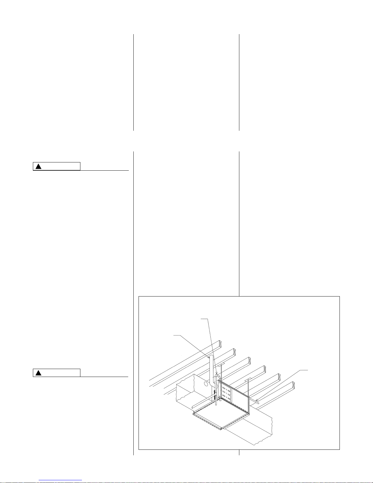
5. IMPORTANT: Support this unit
when installed. For attic or crawl
space installation, horizontal
furnaces may be installed on
combustible wood flooring or by
using support brackets. See Figure
1.
6. IMPORTANT: If installing in a utility
room, be sure the door is wide
enough to:
a. allow the largest part of the
furnace to pass; or
b. allow any other appliance (such
as a water heater) to pass.
The 80PJ and 80LJ series furnaces are
design certified by CSA for use with
natural and propane gases as follows:
As a Category I furnace, it may be
vented vertically with type B-1 vent
pipe and also may be common
vented as described in these
instructions.
This furnace should be installed in
accordance with the American National
Standard Z223.1 - latest edition booklet
entitled “National Fuel Gas Code”
(NFPA 54) (in Canada, CSA B149.1
and .2 Installation Codes for gas
burning appliances), and the
requirements or codes of the local utility
or other authority having jurisdiction
including local plumbing or waste water
codes.
Additional helpful publications available
from the “National Fire Protection
Association” are: NFPA-90A –
Installation of Air Conditioning and
Ventilating Systems 1985 or latest
edition. NFPA-90B – Warm Air Heating
and Air Conditioning Systems 1984.
These publications are available from:
National Fire Protection Association,
Inc.
Batterymarch Park
Quincy, MA 02269
CSA-INTERNATIONAL
178 Rexdale Blvd.
Etobicoke (Toronto), Ontario
Canada M9W, 1R3
GENERAL INFORMATION
LOCATION REQUIREMENTS AND CONSIDERATIONS
WARNING
!
FIGURE 1
HORIZONTAL FURNACE INSTALLED W/SUPPORT BRACKETS
EXHAUST
VENT
GAS
PIPE
ELECTRICAL
CONDUIT
ST-A0799-01
CAUTION
!
6
REDUCED CLEARANCE (IN.)
Model A B C D E
Left Right
Back Top Front Vent
Ship.
Side Side Wgts.
05 14 12
27
/32 10
3
/8 ➀ 11
1
/2 04➁ 01 36➂ 85 lbs.
07 17
1
/2 16
11
/32 12
1
/8 ➀ 15 0 3➁ 01 36➂ 105 lbs.
10(A) 17
1
/2 16
11
/32 12
1
/8 ➀ 15 0 3➁ 01 36➂ 115 lbs.
10(B) 21 19
27
/32 13
7
/8 ➀ 18
1
/2 00 0136➂ 120 lbs.
12 24
1
/2 23
11
/32 15
5
/8 ➀ 22 0 0 0 1 3 6➂ 140 lbs.
15 24
1
/2 23
11
/32 15
5
/8 ➀ 22 0 0 0 1 3 6➂ 150 lbs.
CLEARANCE TO COMBUSTIBLE MATERIAL (INCHES)
UPFLOW AND UPFLOW/HORIZONTAL MODELS
TOP
LEFT SIDE
FRONT
RIGHT SIDE
BOTTOM
24
1
/2
26
13
/16
26
5
/8
24
11
/32
24
11
/32
19
/32
9
/16
24
7
/16
28
1
/16
26
5
/8
14
3
/
8
11
1
/2
34
1
5
/8 DIA.
23
15
20
D
7
/8 DIA.
7
/8 DIA.
19
/32
19
/32
3
/4
14
3
/8
11
1
/
2
1
1
/
4
23
17
/32
C
GAS CONNECTION
ELECTRICAL CONNECTION
OPTIONAL RETURN AIR CUTOUT
(EITHER SIDE) FOR USE WITH
EXTERNAL SIDE FILTER FRAME
LOW VOLTAGE
E
A
B
➀ May require 3” to 4” or 3” or 5” adapter.
➁ May be 0” with type B vent.
➂ May be 1” with type B vent.
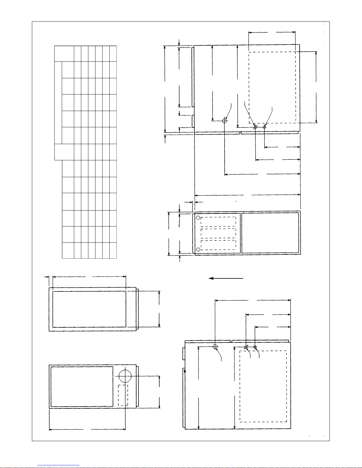
FIGURE 2
UPFLOW AND UPFLOW/HORIZONTAL DIMENSIONS
IMPORTANT: This furnace is not approved or recommended for
installation on its back, with access doors facing upwards.
SUPPLY
AIR
RETURN
AIR
AIRFLOW
7
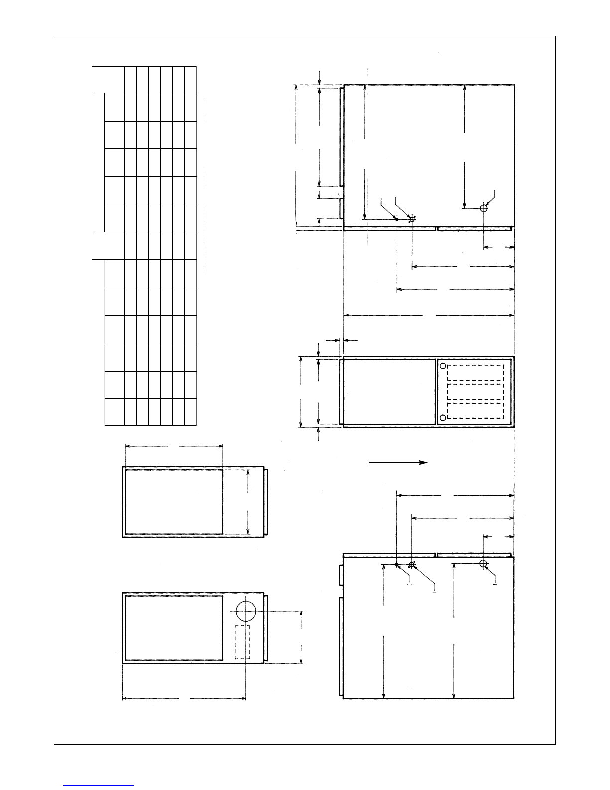
FIGURE 3
DOWNFLOW DIMENSIONS
REDUCED CLEARANCE (IN.)
Model A B C D E
Left Right
Back Top Front Vent
Ship.
Side Side Wgts.
05 14 12
27
/32 10
3
/8 ➀ 13
1
/8 04➁ 0136➂ 85 lbs.
07 17
1
/2
16
11
/32
12
1
/8 ➀ 16
5
/8
03➁ 0136➂ 105 lbs.
10(A) 17
1
/2 16
11
/32 12
1
/8 ➀ 16
5
/8 03➁ 0136➂ 115 lbs.
10(B) 21 19
27
/32 13
7
/8 ➀ 20
1
/8 00 0 166➂ 120 lbs.
12 24
1
/
2 23
11
/
32 15
5
/
8
➀ 23
5
/
8 00 0136➂ 140 lbs.
15 24
1
/2 23
11
/32 15
5
/8 ➀ 23
5
/8 00 0 136➂ 150 lbs.
TOP
BOTTOM
24
1
/2
19
3
/4
C
A
B D
LOW VOLTAGE
GAS CONNECTION
ELECTRIC CONNECTION
E
26
5
/8
26
13
/16
6
3
/16
20
3
/8
23
3
/8
5
/8
5
/8
3
/4
5
/8
34
23
3
/8
20
3
/8
6
3
/16
24
7
/16
26
5
/8
20
1
/8
28
1
/16
7
/8 DIA.
7
/8 DIA.
1
5
/8 DIA.
➀ May require 3” to 4” or 3” or 5” adapter.
➁ May be 0” with type B vent.
➂ May be 1” with type B vent.
CLEARANCE TO COMBUSTIBLE MATERIAL (INCHES)
DOWNFLOW MODELS
NOTE: IN DOWNFLOW CONFIGURATION, OPTIONAL AIR CUTOUT IS NOT PERMITTED.
SUPPLY
AIR
RETURN
AIR
AIRFLOW
8
CLEARANCE –
ACCESSIBILITY
The design of forced air furnaces with
input ratings as listed in the tables on
the following pages are certified by
CSA for the clearances to combustible
materials shown in inches.
See name/rating plate and clearance
label for specific model number and
clearance information.
Service clearance of at least 24 inches
is recommended in front of all furnaces.
ACCESSIBILITY CLEARANCES,
WHERE GREATER, MUST TAKE
PRECEDENCE OVER FIRE
PROTECTION CLEARANCES.
UPFLOW AND HORIZONTAL
FURNACES MUST NOT BE
INSTALLED DIRECTLY ON
CARPETING, TILE OR OTHER
COMBUSTIBLE MATERIAL OTHER
THAN WOOD FLOORING.
INSTALLATION ON A
COMBUSTIBLE MATERIAL CAN
RESULT IN FIRE CAUSING
PROPERTY DAMAGE, SEVERE
PERSONAL INJURY OR DEATH.
DOWNFLOW UNIT DESIGN IS
CERTIFIED FOR INSTALLATION ON
NON-COMBUSTIBLE FLOOR. A
SPECIAL COMBUSTIBLE FLOOR
SUB-BASE IS REQUIRED WHEN
INSTALLING ON A COMBUSTIBLE
FLOOR. FAILURE TO INSTALL THE
SUB-BASE MAY RESULT IN FIRE,
PROPERTY DAMAGE, PERSONAL
INJURY OR DEATH. THIS SPECIAL
BASE IS OFFERED AS AN
ACCESSORY FROM THE FACTORY.
SEE THE CLEARANCE LABEL
LOCATED INSIDE THE FURNACE
FOR THE APPROPRIATE MODEL
NUMBER.
THE SPECIAL BASE IS NOT
REQUIRED WHEN THE FURNACE IS
INSTALLED ON TOP OF AN AIR
CONDITIONING PLENUM.
A gas-fired furnace for installation in a
residential garage must be installed so
that the burner(s) and the ignition
source are located not less than 18”
above the floor and the furnace is
located or protected to avoid physical
damage by vehicles.
UPFLOW UNIT DESIGN REQUIRES
A SOLID METAL BASE PLATE (SEE
TABLE 1 OR FURNACE
CLEARANCE LABEL FOR PART
PLACEMENT OF COMBUSTIBLE
MATERIALS ON, AGAINST OR
AROUND THE FURNACE JACKET
CAN CAUSE AN EXPLOSION OR
FIRE RESULTING IN PROPERTY
DAMAGE, PERSONAL INJURY OR
DEATH. THE FURNACE OWNER
SHOULD BE CAUTIONED THAT THE
FURNACE AREA MUST NOT BE
USED AS A BROOM CLOSET OR
FOR ANY OTHER STORAGE
PURPOSES.
DUCTING
Proper air flow is required for the
correct operation of this furnace. Too
little air flow can cause erratic
operation and can damage the heat
exchanger. The duct system must
carry the correct amount of air for
heating and cooling. Position the unit
minimize long runs or runs with many
turns and elbows.
Size the ducts according to acceptable
industry standards and methods. The
total static pressure drop (including
evaporator coil, if used) of the entire
system should not exceed 0.5” w.c. Be
sure to have adequate space for unit
filter.
IMPORTANT: Some high efficiency
filters have a greater than normal
resistance to air flow. This can
adversely affect furnace operation. BE
SURE TO CHECK AIR FLOW if using
any filter other than the factoryprovided filter.
NOTE: DO NOT take return air from
bathrooms, kitchens, furnace rooms,
garages, utility or laundry rooms, or
cold areas.
IMPORTANT: When using outside air,
design and adjust the system to
maintain a return air temperature
above 50°F during the heating season.
NEVER ALLOW PRODUCTS OF
COMBUSTION OR THE FLUE
PRODUCTS TO ENTER THE
RETURN AIR DUCTWORK, OR THE
CIRCULATING AIR SUPPLY. ALL
RETURN DUCTWORK MUST BE
ADEQUATELY SEALED AND
SECURED TO THE FURNACE WITH
SHEET METAL SCREWS, AND
JOINTS TAPED. WHEN A FURNACE
IS MOUNTED ON A PLATFORM,
WITH RETURN THROUGH THE
BOTTOM, IT MUST BE SEALED
AIRTIGHT BETWEEN THE FURNACE
NUMBER) BE IN PLACE WHEN THE
FURNACE IS INSTALLED WITH SIDE
OR REAR AIR RETURN DUCTS.
FAILURE TO INSTALL A BASE PLATE
COULD CAUSE PRODUCTS OF
COMBUSTION TO BE CIRCULATED
INTO THE LIVING SPACE AND
CREATE POTENTIALLY HAZARDOUS
CONDITIONS, INCLUDING CARBON
MONOXIDE POISONING.
SITE SELECTION
1. Select a site in the building near the
center of the proposed, or existing,
duct system.
2. Give consideration to the vent system
piping when selecting the furnace
location. Be sure the venting system
can travel from the furnace to the
termination with minimal length and
elbows.
3. Locate the furnace near the existing
gas piping. Or, if running a new gas
line, locate the furnace to minimize
the length and elbows in the gas
piping.
4. Locate the furnace to maintain proper
clearance to combustibles as shown
in Figures 2 & 3.
WHEN COILS ARE USED WITH AIR
HANDLERS OR FURNACES AND
INSTALLED ABOVE A FINISHED
CEILING OR LIVING AREA, IT IS
RECOMMENDED THAT AN
AUXILIARY SHEET METAL
CONDENSATE DRAIN PAN BE
FABRICATED AND INSTALLED
UNDER ENTIRE UNIT. FAILURE TO
DO SO CAN RESULT IN PROPERTY
DAMAGE.
COMBUSTIBLE MATERIAL MUST
NOT BE PLACED ON OR AGAINST
THE FURNACE JACKET OR WITHIN
THE SPECIFIED CLEARANCES OF
THE VENT PIPE. THE AREA AROUND
THE FURNACE MUST BE KEPT
CLEAR AND FREE OF ALL
COMBUSTIBLE MATERIALS
INCLUDING GASOLINE AND OTHER
FLAMMABLE VAPORS AND LIQUIDS.
CAUTION
!
WARNING
!
WARNING
!
WARNING
!
TABLE 1
FURNACE BASE BASE
WIDTH
PLATE NO. PLATE SIZE
14” RXGB-D14 11
5
/8” x 239/16”
17
1
/2” RXGB-D17 151/8” x 239/16”
21” RXGB-D21 18
5
/8” x 239/16”
24
1
/2” RXGB-D24 255/8” x 239/16”
9
AND THE RETURN AIR PLENUM.
THE RETURN AIR PLENUM MUST
BE PERMANENTLY ENCLOSED.
NEVER USE A DOOR AS A PART OF
THE RETURN AIR PLENUM. THE
FLOOR OR PLATFORM MUST
PROVIDE SOUND PHYSICAL
SUPPORT OF THE FURNACE,
WITHOUT SAGGING, CRACKS,
GAPS, ETC., AROUND THE BASE AS
TO PROVIDE A SEAL BETWEEN
THE SUPPORT AND THE BASE.
FAILURE TO PREVENT PRODUCTS
OF COMBUSTION FROM BEING
CIRCULATED INTO THE LIVING
SPACE CAN CREATE POTENTIALLY
HAZARDOUS CONDITIONS,
INCLUDING CARBON MONOXIDE
POISONING THAT COULD RESULT
IN PERSONAL INJURY OR DEATH.
DO NOT, UNDER ANY
CIRCUMSTANCES, CONNECT
RETURN OR SUPPLY DUCTWORK
TO OR FROM ANY OTHER HEAT
PRODUCING DEVICE SUCH AS A
FIREPLACE INSERT, STOVE, ETC.
DOING SO MAY RESULT IN FIRE,
CARBON MONOXIDE POISONING,
EXPLOSION, PERSONAL INJURY
OR PROPERTY DAMAGE.
BLOWER AND BURNERS MUST
NEVER BE OPERATED WITHOUT
THE BLOWER DOOR IN PLACE.
THIS IS TO PREVENT DRAWING
GAS FUMES (WHICH COULD
CONTAIN HAZARDOUS CARBON
MONOXIDE) INTO THE HOME THAT
COULD RESULT IN PERSONAL
INJURY OR DEATH.
UPFLOW UNITS
1. Set furnace in place and connect the
return duct or return air cabinet to
unit. Make the connection air-tight to
prevent entraining combustion
gases from any adjacent fuelburning appliances. Unit return air
may be connected on the sides or
bottom of the return air
compartment.
a. Openings in the side must be cut
out the full width of the knockouts
on the unit. If using side return air,
THE BOTTOM base plate must
be installed.
NOTE: Where the maximum
airflow is 1800 CFM or more, both
sides or the bottom must be used
for return air.
b. If using bottom return air, place
furnace over return air plenum and
seal furnace bottom to return air
plenum.
A SOLID METAL BASE PLATE, (SEE
TABLE 1) MUST BE IN PLACE
WHEN THE FURNACE IS
INSTALLED WITH SIDE OR REAR
AIR RETURN DUCTS. FAILURE TO
INSTALL A BASE PLATE COULD
CAUSE PRODUCTS OF
COMBUSTION TO BE CIRCULATED
INTO THE LIVING SPACE AND
CREATE POTENTIALLY
HAZARDOUS CONDITIONS,
INCLUDING CARBON MONOXIDE
POISONING OR DEATH.
2. If summer air conditioning is desired,
position the indoor coil on the top of
the unit. Insure that no air can
bypass this coil.
3. Connect the supply air plenum to the
furnace plenum opening.
DOWNFLOW UNITS
THE DOWNFLOW FURNACE
DESIGN IS CERTIFIED FOR
INSTALLATION ON A NONCOMBUSTIBLE FLOOR. IF
INSTALLED ON A COMBUSTIBLE
FLOOR, USE THE SPECIAL BASE
SPECIFIED ON THE FURNACE
CLEARANCE LABEL. FAILURE TO
INSTALL THE SPECIAL BASE MAY
RESULT IN FIRE, PROPERTY
DAMAGE, PERSONAL INJURY OR
DEATH. THIS SPECIAL BASE IS
SHIPPED FROM THE FACTORY AS
AN ACCESSORY.
1. Position the unit over the supply air
plenum and connect.
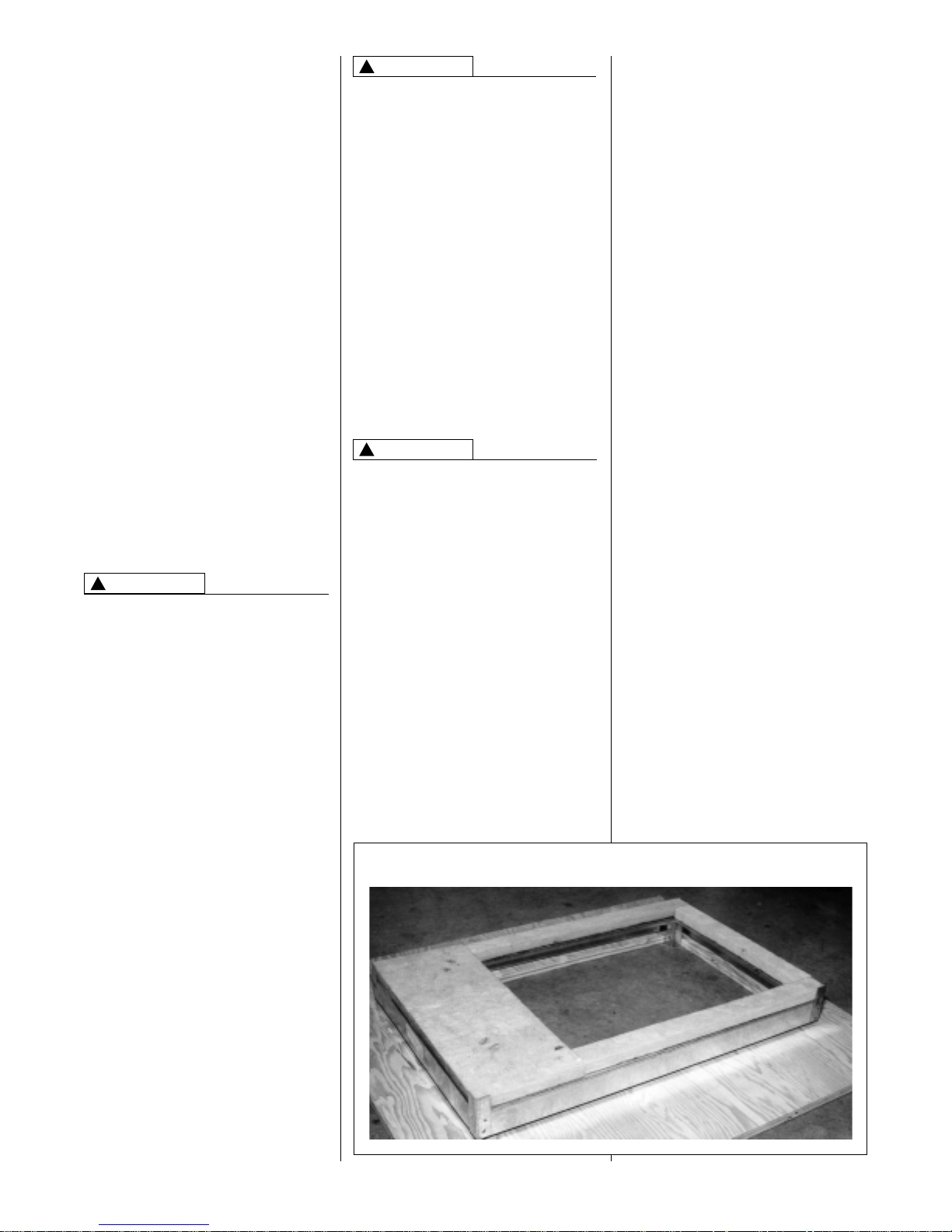
a. If installing on a combustible floor
and not using an evaporator
coil box, install the special
combustible floor base.
See Figure 4.
b. If summer air conditioning is
desired, position the indoor coil on
the bottom of the unit. Insure that
no air can bypass this coil.
2. Connect the return air ducting to the
return air opening at the top of the
unit. Make the connection air tight to
prevent entraining combustion
gases from an adjacent fuel-burning
appliance.
HORIZONTAL UNITS
1. Unit can be mounted left or right
side airflow configuration.
2. Position the unit on adequate
supports or by using support
brackets (see Figure 1) and connect
supply plenum.
3. If summer air conditioning is desired,
position the indoor coil on the supply
air side of the unit. Insure that no air
can bypass this coil.
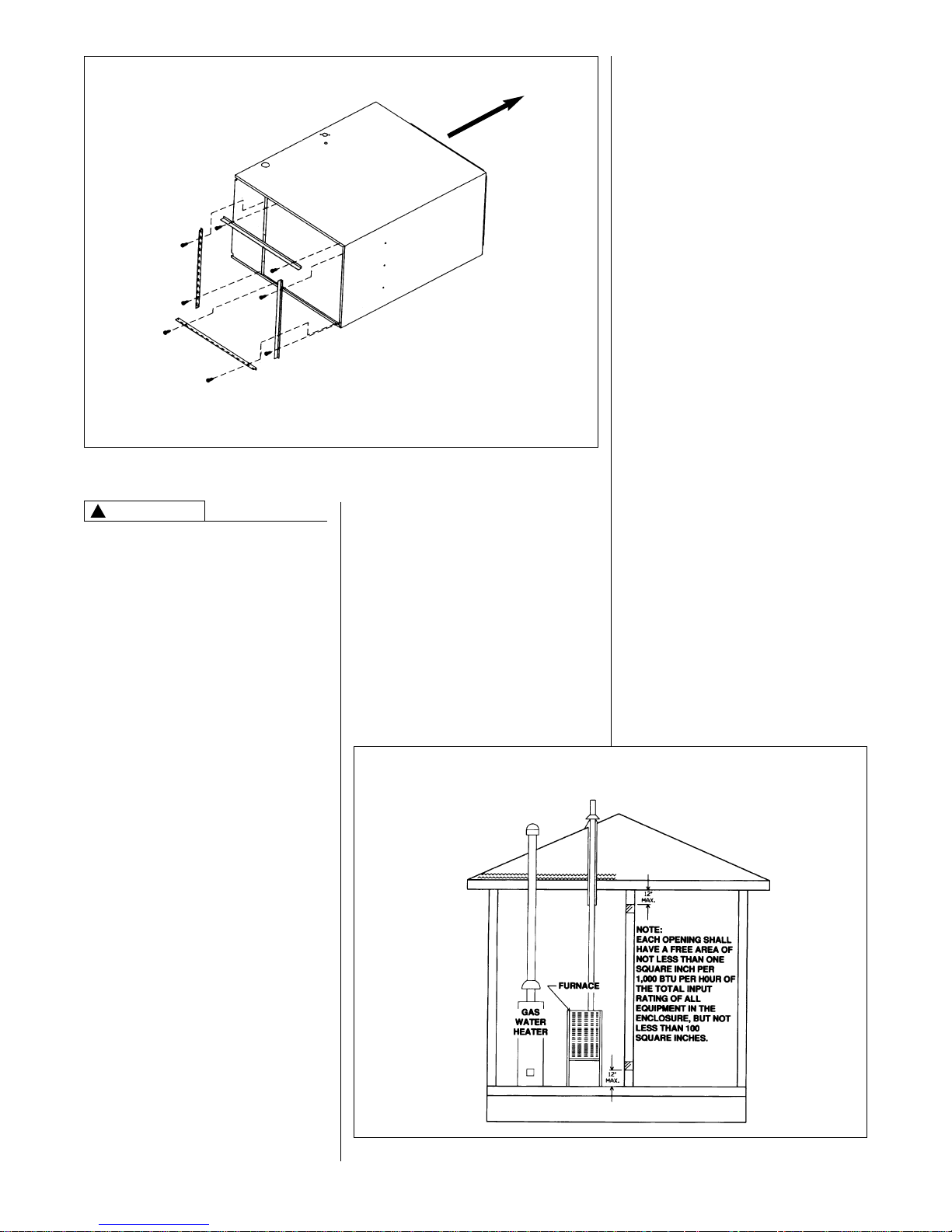
4. Secure the four angle brackets
shipped with the unit to the return air
opening. See Figure 5. Connect the
return air ducting to the return air
opening at the top of the unit. Make
the connection air tight to prevent
entraining combustion gases from
an adjacent fuel-burning appliance.
NOTE: Do not block furnace access
with support rods. Maintain clearances
recommended in Figure 2. Allow
enough space for proper service,
maintenance or replacement of the
heat exchanger and blower assembly.
FIGURE 4
COMBUSTIBLE FLOOR BASE
WARNING
!
WARNING
!
WARNING
!
10
THIS FURNACE AND ANY OTHER
FUEL-BURNING APPLIANCE MUST
BE PROVIDED WITH ENOUGH
FRESH AIR FOR PROPER
COMBUSTION AND VENTILATION
OF THE FLUE GASES. MOST
HOMES WILL REQUIRE THAT
OUTSIDE AIR BE SUPPLIED INTO
THE FURNACE AREA. FAILURE TO
DO SO CAN CAUSE DEATH FROM
CARBON MONOXIDE POISONING.
Adequate facilities for providing air for
combustion and ventilation must be
provided in accordance with section
5.3, Air for Combustion and
Ventilation, of the National Fuel Gas
Code, ANSI, Z223.1 latest edition or
CSA B149.1 and .2 or, applicable
provisions for the local building codes,
and not obstructed so as to prevent the
flow of air to the furnace.
OVERTEMPERATURE
SAFETY SWITCHES
This furnace is equipped with safety
switches in the burner compartment to
protect against overtemperature
conditions caused by inadequate
combustion air supply. The switches
are located just above the burners on
the furnace center panel on upflow and
downflow models and also on each
side of the burners on
upflow/horizontal and horizontal “only”
models, and must be manually reset if
tripped. DO NOT jumper this switch. If
this switch should trip, a qualified
furnace installer, service agency or the
FIGURE 5
HORIZONTAL RETURN AIR DUCT
FIGURE 6
AIR FROM HEATED SPACE
gas supplier should be called to check
and/or correct for adequate combustion
air supply. If this unit is mounted in a
closet, the door must be closed when
making this check of the installation.
DO NOT reset the overtemperature
switch without taking corrective action
to assure that an adequate supply of
combustion air is maintained under all
conditions of operation.
Replace this switch only with the
identical replacement part.
COMBUSTION AIR
REQUIREMENTS
IMPORTANT: Air for combustion and
ventilation must not come from a
corrosive atmosphere. Any failure due
to corrosive elements in the
atmosphere is excluded from warranty
coverage.
The following types of installation may
require OUTDOOR AIR for
combustion, due to chemical
exposures:
• Commercial buildings
• Buildings with indoor pools
• Furnaces installed in laundry rooms
• Furnaces in hobby or craft rooms
• Furnaces installed near chemical
storage areas.
Exposure to the following substances
in the combustion air supply may also
require OUTDOOR AIR for
combustion:
• Permanent wave solutions
• Chlorinated waxes and cleaners
• Chlorine-based swimming pool
chemicals
• Water softening chemicals
• De-icing salts or chemicals
• Carbon tetrachloride
• Halogen type refrigerants
• Cleaning solvents (such as
perchloroethylene)
• Printing inks, paint removers,
varnishes, etc.
• Hydrochloric acid
• Cements and glues
• Antistatic fabric softeners for clothes
dryers
• Masonry acid washing materials
COMBUSTION AND VENTILATION AIR
WARNING
!
FOUR ANGLE BRACKETS ARE SHIPPED WITH EACH
UNIT THAT CAN BE INSTALLED HORIZONTALLY. THESE
BRACKETS MAY BE USED TO SECURE THE RETURN
AIR DUCT TO A HORIZONTAL UNIT.
(LEFT-HAND AIRFLOW POSITION SHOWN)
AIRFLOW
11
Combustion air must be free of acid
forming chemicals; such as sulphur,
fluorine and chlorine. These elements
are found in aerosol sprays,
detergents, bleaches, cleaning
solvents, air fresheners, paint and
varnish removers, refrigerants and
many other commercial and household
products. Vapors from these products
when burned in a gas flame form acid
compounds. The acid compounds
increase the dew point temperature of
the flue products and are highly
corrosive after they condense.
ALL FURNACE INSTALLATIONS
MUST COMPLY WITH THE
NATIONAL FUEL GAS CODE AND
LOCAL CODES TO PROVIDE
ADEQUATE COMBUSTION AND
VENTILATION AIR FOR THE
FURNACE. FAILURE TO DO SO CAN
CREATE HAZARDOUS CONDITIONS
RESULTING IN PROPERTY
DAMAGE, BODILY INJURY OR
DEATH FROM SMOKE, FIRE OR
CARBON MONOXIDE.
Combustion air requirements are
determined by whether the furnace is
in an open (unconfined) area or in a
confined space such as a closet or
small room.
EXAMPLE 1.
FURNACE LOCATED IN AN
UNCONFINED SPACE
Using indoor air for combustion.
An unconfined space must have at
least 50 cubic feet for each 1,000
BTUH of the total input for all
appliances in the space. Here are a
few examples of the room sizes
required for different inputs. The sizes
are based on 8 foot ceilings.
BTUH Minimum Sq. Feet Typical Room Size
Input
With 8' Ceiling With 8' Ceiling
50,000 312 14*x24* or 18*x18*
75,000 469 15*x31* or 20*x24*
100,000 625 20*x31* or 25*x25*
125,000 833 23*x34* or 26*x30*
150,000 938 25*x38* or 30*x31*
If the open space containing the
furnace is in a building with tight
construction (contemporary
construction), outside air may still be
required for the furnace to operate and
vent properly. Outside air openings
should be sized the same as for a
confined space.
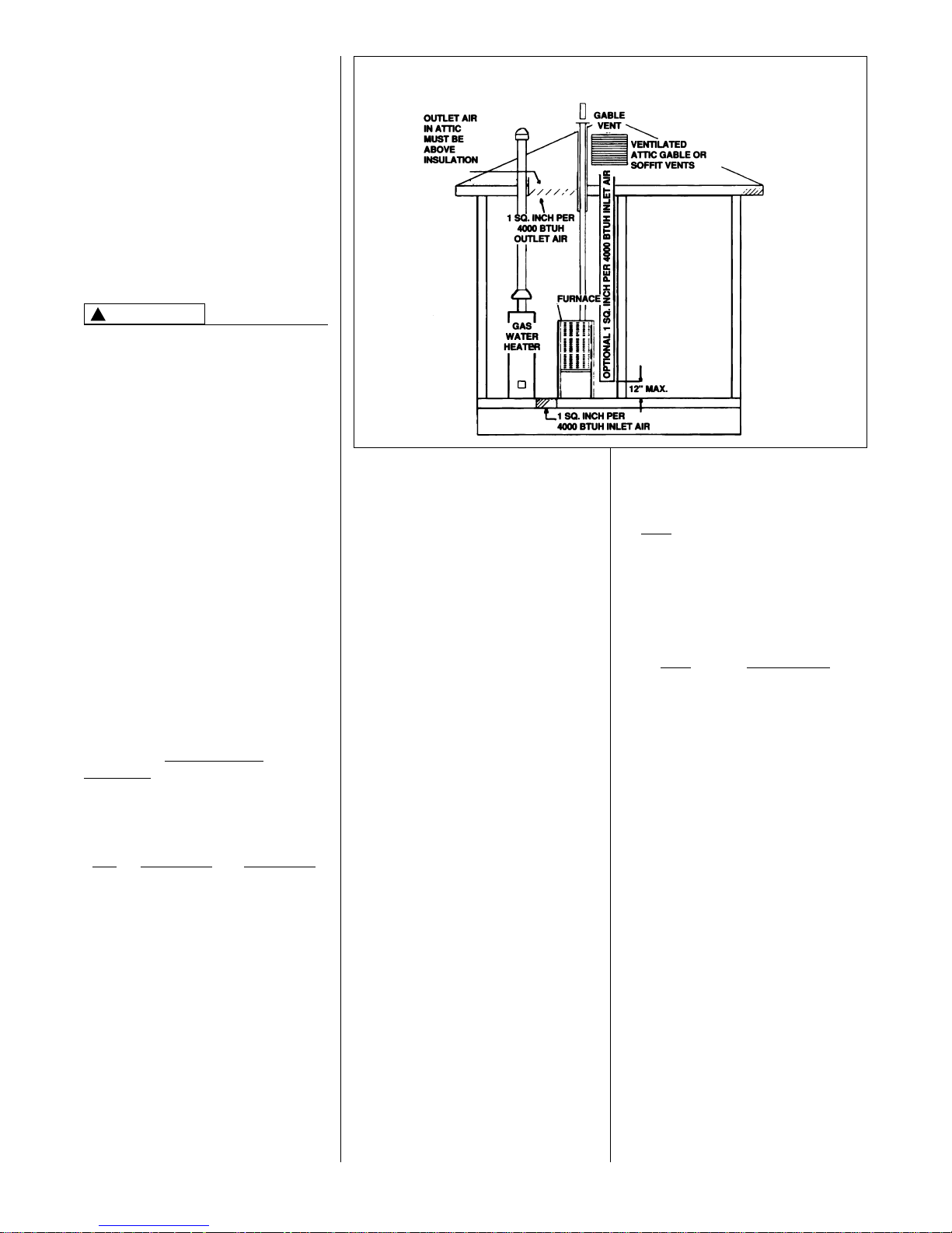
FIGURE 7
AIR FROM ATTIC/CRAWL SPACE
EXAMPLE 2.
FURNACE LOCATED IN A
CONFINED SPACE
A confined space (any space smaller
than shown above as “unconfined”)
must have openings into the space
which are located in accordance with
the requirements set forth in the
following subsections A and B. Size the
openings by how they are connected to
the heated area or to the outside, and
by the input of all appliances in the
space.
If confined space is within a building
with tight construction, combustion air
must be taken from outdoors or area
freely communicating with the
outdoors.
A. USING INDOOR AIR FOR
COMBUSTION (FIGURE 6)
IMPORTANT: Air should not be taken
from a heated space with a fireplace,
exhaust fan or other device that may
produce a negative pressure.
If combustion air is taken from the
heated area, the openings must
each
have at least 100 square
inches of free area. Each opening
must have at least one square inch
of free area for each 1,000 Btuh of
total input in the space. Here are
some examples of typical openings
required.
Btuh Free Area
Input Each Opening
100,000 100 Square Inches
150,000 150 Square Inches
B. USING OUTDOOR AIR FOR
COMBUSTION (FIGURE 7)
IMPORTANT: Never take
combustion air from an attic space
that is equipped with power
ventilation.
The confined space must
communicate with the outdoors
according to Methods 1 and 2. The
minimum air opening dimension
shall not be less than 3 inches.
When using ducts, they shall be of
the same cross-sectional area as
the free area of the openings to
which they connect.
WARNING
!
12
IMPORTANT: If the furnace is in a
location with an exhaust fan, there
must be sufficient ventilation to prevent
the exhaust fan from creating a
negative pressure in the room.
Combustion air openings must NOT
BE RESTRICTED in any manner.
CONSULT LOCAL CODES FOR
SPECIAL REQUIREMENTS.
Air opening in the furnace casing front,
return air grilles, and warm air registers
must not be obstructed.
B: Method 1
Provide two permanent openings,
one located within 12 inches of the
top and one located within 12
inches of the bottom of the
enclosure. Each opening shall
communicate directly, or by ducts,
with the outdoors or spaces (crawl
or attic) that freely communicate
with the outdoors.
a. Where directly communicating
with the outdoors or where
communicating to the outdoors
through VERTICAL DUCTS,
each opening shall have a
minimum free area of 1 square
inch for each 4000 BTUH of
total appliance input rating in the
enclosure (see Figure 7). Here
are typical duct sizes:
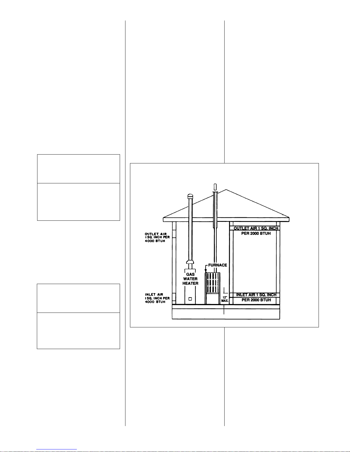
b. Where communicating with
outdoors through HORIZONTAL
DUCTS, each opening shall have
a minimum free area of 1 square
inch for each 2000 BTUH of
total input rating for all equipment
in the enclosure (see Figure 8).
Here are typical duct sizes:
FIGURE 8
OUTSIDE AIR USING A HORIZONTAL INLET & OUTLET
B: Method 2
One permanent opening, located within
12 inches of the top of the enclosure,
shall be permitted where the
equipment has clearances of at least 1
inch from the sides and back and 6
inches from the front of the appliance.
The opening shall directly
communicate with the outdoors or
communicate through a vertical or
horizontal duct to the outdoors or
spaces (crawl or attic) that freely
communicate with the outdoors and
have a minimum free area of:
a. One square inch for each 3000
BTUH of the total input rating of all
equipment located in the enclosure,
AND
b. Not less than the sum of the areas of
all vent connectors in the confined
space.
VERTICAL OUTDOOR AIR
OPENING DIMENSIONS
BTUH Free Area Round
Input Each Opening Pipe Size
50,000 12.50 sq. inches 4”
75,000 18.75 sq. inches 5”
100,000 25.00 sq. inches 6”
125,000 31.25 sq. inches 7”
150,000 37.50 sq. inches 7”
HORIZONTAL OUTDOOR AIR
OPENING DIMENSIONS
BTUH Free Area Round
Input Each Opening Pipe Size
50,000 25.00 sq. inches 6”
75,000 37.50 sq. inches 7”
100,000 50.00 sq. inches 8”
125,000 62.50 sq. inches 9”
150,000 75.00 sq. inches 10”
 Loading...