

Page 1

Vulcan
Service Manual
ICE Vulcan Service Manual
Page 2

For Customers in the European Union
This equipment displays the CE mark to indicate conformance to the following legislation:
EMC Directive 2004/108/EC
Essential health and safety requirements relating to electromagnetic
compatibility. CISPR22:2008 (Class A) Information Technology
Equipment - Radio
Disturbance Characteristics - Limits and
methods of measurement.
IEC 61000-6-2 Generic standards - Immunity for
industrial environments.
IEC 61000-6-4 Generic Emissions Standard for Heavy
Industrial Environments.
IEC 61000-3-2 Limits for harmonic current emissions
(equipment input current <=16A per phase).
IEC 61000-3-3 Limitation of voltage changes, voltage
fluctuations and flicker in public low voltage
supply systems for equipment with rated
current <=16A per phase and not subject to
conditional connection.
Low Voltage Directive 2006/95/EC
Essential health and safety requirements relating to electrical equipment designed
for use within certain voltage limits.
EN 60950-1 Safety requirements for information
technology equipment including electrical
business equipment
IEC 60950-1
Machinery Directive 2006/42/EC
EN 60204-1
IEC 60204-1
EN ISO 12100 Safety standard for machinery.
Safety of machinery - Electrical
equipment of machines.
Page 3

ICE Vulcan Service Manual
EN ISO 13849-1 Safety requirements and guidance on the
RoHS Directive 2011/65/EC
Restriction of the use of certain hazardous substances (RoHS)
EN 50581 Technical documentation for the
Support and Training
Contact Information
principles for the design and integration of
safety-related parts of control systems
(SRP/CS), including the design of software.
assessment of electrical and electronic
products with respect to the restriction of
hazardous substances.
If you have any questions or need assistance, contact ICE on
01159 640144
Interactive Coding Equipment (ICE)
Olympic House
Willow Drive
Sherwood Park
Nottingham
NG15 0DP
Web: www.interactivecoding.co.uk
Page 4

ICE Vulcan Service Manual
Customer Training
If you wish to perform your own service and maintenance on the LPA, ICE highly recommends
you complete a Customer Training Course on the LPA.
For more information, please contact us on
01159 640144
Interactive Coding Equipment (ICE)
Olympic House
Willow Drive
Sherwood Park
Nottingham
NG15 0DP
Web: www.interactivecoding.co.uk
Note: The manuals are intended to be supplements to (and not replacements for) ICE.
Customer Training.
Page 5

ICE Vulcan Service Manual
Table of Contents
Compliance Information
For Customers in the U.S.A. .......................................................................................................... i
For Customers in Canada ............................................................................................................. ii
For Customers in the European Union ......................................................................................... ii
Support and Training
Contact Information ................................................................................................................... iv
Service Program .......................................................................................................................... iv
Customer Training ....................................................................................................................... v
Chapter 1 — Introduction
Equipment Description ............................................................................................................1–1
About the Manual. ...................................................................................................................1–1
Related Publications ................................................................................................................1–2
Language Codes .......................................................................................................................1–2
Content Presentation ..............................................................................................................1–3
Positional References ..............................................................................................................1–3
Units of Measurement ............................................................................................................ 1–3
Safety Information ...................................................................................................................1–4
Notes ........................................................................................................................................1–5
Abbreviations and Acronyms...................................................................................................1–5
Chapters in the Manual .......................................................................................................... 1–6
Chapter 2 — Safety
Introduction ............................................................................................................................ 2–2
Equipment Safety Guidelines ................................................................................................. 2–2
Comply with Electrical Codes ..................................................................................................2–3
Electrical Power .......................................................................................................................2–4
Do Not Remove Warning Label ...............................................................................................2–5
Grounding and Bonding ...........................................................................................................2–5
Printhead ................................................................................................................................ 2–6
Print Ribbon Safety Guidelines ................................................................................................ 2–6
Placement of the Equipment ...................................................................................................2–7
Using Accessories.....................................................................................................................2–7
Other Important Guidelines ....................................................................................................2–7
Cleaning Safety Guidelines ......................................................................................................2–8
Equipment Handling Safety Guidelines .................................................................................. 2–8
Chapter 3 — Main Parts
Page 6

ICE Vulcan Service Manual
System Overview .................................................................................................................... 3–2
CLARITY Display ................................................................................................................. 3–3
Labeller .............................................................................................................................. 3–4
Main Controller Board for the LPA .................................................................................... 3–4
Gap Sensor and Print Roller Sensor PCB............................................................................ 3–5
Ribbon and Printhead Sensor PCB ..................................................................................... 3–5
Label Drive Motor PCB ....................................................................................................... 3–6
CLARiTY Display PCB .......................................................................................................... 3–6
Supply Reel Hall Sensor PCB .............................................................................................. 3–7
Dancer Arm Sensor PCB ..................................................................................................... 3–7
Connectors ......................................................................................................................... 3–8
Ribbon Web ..................................................................................................................... 3–14
Label Web ........................................................................................................................ 3–16
Emergency Stop (E-Stop) ................................................................................................. 3–18
Sensors ............................................................................................................................. 3–19
Printhead ......................................................................................................................... 3–20
Chapter 4 — Installation
Tools and Supplies ............................................................................................................. 4–3
Tools ................................................................................................................................... 4–3
Supplies .............................................................................................................................. 4–3
Unpacking and Inspecting the Labeller ............................................................................. 4–3
Selection of a Suitable Installation Position ...................................................................... 4–3
Positioning of Labeller/Peel Tip ......................................................................................... 4–4
Installing the Label Applicator ........................................................................................... 4–5
Assembling the Stand ........................................................................................................ 4–5
Mounting the LPA .............................................................................................................. 4–9
Setting up the Production Line ........................................................................................ 4–11
Mounting the CLARiTY Display ........................................................................................ 4–13
Instating the Product Detector ........................................................................................ 4–14
Cable Connections ........................................................................................................... 4–15
Loading the Web .............................................................................................................. 4–17
Turning On the Machine .................................................................................................. 4–23
Setting up the User Interface .......................................................................................... 4–23
Chapter 5 — CLARiTY Operating System
Getting started with the CLARiTY ...................................................................................... 5–1
Page 7

ICE Vulcan Service Manual
Using the Home Page ........................................................................................................ 5–2
How to Configure the LPA ................................................................................................. 5–6
CLARiTY Configuration Manager ....................................................................................... 5–6
How to Connect the CLARiTY Configuration
Manager to the LPA ........................................................................................................... 5–8
How to Edit the Parameters ............................................................................................ 5–14
How to Save the Changes in the LPA ............................................................................... 5–15
How to Archive the Current Parameters ......................................................................... 5–16
How to Load a Saved Archive .......................................................................................... 5–17
Creating, Editing and Restoring a USB Archive on a
CLARiTY LPA ..................................................................................................................... 5–17
How to Set the External Outputs ..................................................................................... 5–21
External Outputs .............................................................................................................. 5–21
Working with Passwords ................................................................................................. 5–23
CLARiTY Power Saving ..................................................................................................... 5–25
How to Configure the Job Settings .................................................................................. 5–27
Job Creation and Settings ................................................................................................ 5–27
CLARiTY Configuration Settings ....................................................................................... 5–28
Managing Clones ............................................................................................................. 5–31
How to Create a Clone ..................................................................................................... 5–31
How to Restore a Clone ................................................................................................... 5–34
Chapter 6 — Maintenance and Troubleshooting
Maintenance ...................................................................................................................... 6–1
Preventive Maintenance Schedule .................................................................................... 6–1
Replacement Instructions .................................................................................................. 6–2
Motor Calibration Wizard .................................................................................................. 6–4
Updating the CLARiTY Operating System .......................................................................... 6–9
Troubleshooting............................................................................................................... 6–14
Diagnostics Wizard .......................................................................................................... 6–14
LED Indicator Description ................................................................................................ 6–17
CLARiTY Error Messages .................................................................................................. 6–18
Barcode Scanner Faults and Warnings ............................................................................ 6–27
Job File Faults and Warnings ........................................................................................... 6–28
CLARiTY Display Faults ..................................................................................................... 6–28
I/O Faults ......................................................................................................................... 6–28
Label Web Faults ............................................................................................................. 6–29
Page 8

ICE Vulcan Service Manual
Chapter 7 — Illustrated Parts List
How to Read the IPL .......................................................................................................... 7–1
Illustrations ........................................................................................................................ 7–1
Notes .................................................................................................................................. 7–2
LPA Assembly ..................................................................................................................... 7–3
LPA ..................................................................................................................................... 7–4
Label Web .......................................................................................................................... 7–8
CLARiTY Display................................................................................................................ 7–14
Printhead Assembly ......................................................................................................... 7–16
Ribbon .............................................................................................................................. 7–23
Accessories ...................................................................................................................... 7–25
Stands .............................................................................................................................. 7–25
Additional Accessories ..................................................................................................... 7–28
Accessories Cables ........................................................................................................... 7–29
Cables ............................................................................................................................... 7–29
Chapter 8 — Master Slave Setup
Working with Master/Slave ............................................................................................... 8–1
Master/Slave Benefits ....................................................................................................... 8–1
Master/Slave Applications ................................................................................................. 8–2
Master/Slave Terminology ................................................................................................ 8–2
LPA Terminology ................................................................................................................ 8–2
Physical Installation ........................................................................................................... 8–3
Software Configuration ..................................................................................................... 8–4
Master/Slave Basic and Advanced Configuration ............................................................. 8–5
Auto-Changeover Mode .................................................................................................. 8–17
Using Master/Slave Mode - Group Job Select Mode ...................................................... 8–21
The Master LPA ................................................................................................................ 8–21
The Slave LPAs ................................................................................................................. 8–25
Using Master/Slave Mode - Group Control Mode .......................................................... 8–25
The Master LPA ................................................................................................................ 8–25
The Slave LPAs ................................................................................................................. 8–28
Disabling Master/Slave Mode ......................................................................................... 8–28
Disabling Auto-Changeover Mode................................................................................... 8–31
Page 9

9
ICE Vulcan Service Manual
Appendix A — Specifications
Technical Drawings . . . . . . . . . . . . . . . . . . . . . . . . . . . . . . . . . . . . . . . . A–1
CLARiTY Display . . . . . . . . . . . . . . . . . . . . . . . . . . . . . . . . . . . . . . A–1
Label Printer Applicator. . . . . . . . . . . . . . . . . . . . . . . . . . . . . . . . . A–2
Technical Specifications . . . . . . . . . . . . . . . . . . . . . . . . . . . . . . . . . . . . . A–3
Electrical Specifications . . . . . . . . . . . . . . . . . . . . . . . . . . . . . . . . . . . . . A–3
System Specifications . . . . . . . . . . . . . . . . . . . . . . . . . . . . . . . . . . . . . . . A–4
External Connectors and Interface Specifications . . . . . . . . . . . A–4
Appendix B — CLARiTY Configuration Manager
Introduction . . . . . . . . . . . . . . . . . . . . . . . . . . . . . . . . . . . . . . . . . . . . . . . .B–1
CLARiTY Configuration Manager . . . . . . . . . . . . . . . . . . . . . . . . . . . . .B–2
Appendix C — Main Board Test Points
Main Board Test Points . . . . . . . . . . . . . . . . . . . . . . . . . . . . . . . . . . . . . C–1
Appendix D — Theory Of Printing
Printing. . . . . . . . . . . . . . . . . . . . . . . . . . . . . . . . . . . . . . . . . . . . . . . D–2
Appendix E — Availability
Overall Equipment Effectiveness - Availability Tools . . . . . . . . . . . . E–1
Introduction. . . . . . . . . . . . . . . . . . . . . . . . . . . . . . . . . . . . . . . . . . . . E–1
Equipment Availability . . . . . . . . . . . . . . . . . . . . . . . . . . . . . . . . . . E–1
Operational Availability . . . . . . . . . . . . . . . . . . . . . . . . . . . . . . . . . E–2
Availability Page. . . . . . . . . . . . . . . . . . . . . . . . . . . . . . . . . . . . . . . . E–3
Glossary
Page 10

Equipment Description 1-1
ICE Vulcan Service Manual
Introduction
This chapter contains the following topics:
•
Equipment description
•
About the manual
•
Related publications
•
Content presentation
•
Abbreviations and acronyms
•
Chapters in the manual
Equipment Description
The Vulcan is a smarter print and apply labeller that eliminates unscheduled downtime and
reduces costs and errors in case coding operations. The Label Printer Applicator is a simple,
reliable system with a minimum number of wear parts, and zero manual adjustments. Applying
Intelligent Motion
addition, Direct Apply provides accurate placement of on-demand labels at high speed without
the need for an applicator (top or side applications only), enabling it to never miss a pack even
during build-back.
Vulcan maximizes uptime, increase productivity and remove the risk of mislabelled packages
by using the most intelligent and user friendly labelling system.
About the Manual
TM
technology ensures automatic and precise control of the entire system. In
The Service Manual is intended for the use of technicians servicing the LPA. The Service Manual
contains the configuration, maintenance, and troubleshooting procedures.
Page 11

Equipment Description 1-1
ICE Vulcan Service Manual
Code
Language
Availability
(see
01
English (US)
*
+
02
French
* 03
German
*
04
Spanish
*
05
Portuguese Brazilian
*
06
Japanese
*
07
Russian
*
08
Italian
*
09
Dutch
*
10
Chinese (Simplified)
*
11
Arabic
*
12
Korean
*
13
Thai
*
15
Norwegian
*
16
Finnish
*
17
Swedish
*
Related Publications
The following manuals are available for reference: Vulcan Operator
Manual, Part Number: 462469. Tamp Applicator Addendum, Part Number:
462475-01.
Language Codes
When you order this manual, make sure to add the 2-digit language code at the end of the
part number. For example, the English UK version of the service manual is part number
462470-21. Table 1-1 shows the list of language codes that you can use to identify the
translated versions of this manual.
Note: The availability of the Operator Manual is indicated by an asterisk (*). Availability of
the Service Manual is indicated by a plus sign (+). For more information, contact the ICE
distributor or subsidiary.
Table 1-1: List of Language Codes
Page 12

Content Presentation 1-3
ICE Vulcan Service Manual
Code
Language
Availability
(see
18
Danish
*
19
Greek
*
20
Hebrew
*
21
English (UK)
*
+
23
Polish
*
24
Turkish
*
25
Czech
* 26
Hungarian
*
33
Vietnamese
*
34
Bulgarian
*
36
Chinese (Traditional)
*
Table 1-1: List of Language Codes (Continued)
Content Presentation
This Service Manual contains different types of information like safety guidelines, additional
notes, CLARiTY configuration manager terminologies and so on. To help you identify the
different types of information, different writing styles are used in this manual.
Positional References
Positions and directions like left, right, front, rear, to the right and to the left are with respect
to the CLARiTY display when you see it from the front.
Units of Measurement
This manual uses metric units of measurement. The equivalent English measures are included in
parenthesis. For example, 240 mm (9.44 inches).
Page 13

Content Presentation 1-3
ICE Vulcan Service Manual
Safety Information
Specific safety information is listed throughout this manual in the form of Warning and
Caution statements. Pay close attention to these statements as they contain important
information that help in avoiding potential hazards to yourself or to the equipment.
Warning
•
The warning statements indicate hazards or unsafe practices that can cause severe personal
injury or death.
•
They have a triangular symbol with an exclamation mark to the immediate left of the
text
•
They are always preceded by the word “Warning”
•
They are always found before the step or information referring to the hazard
For example:
Warning
PERSONAL INJURY. All electrical wiring and connections must comply with applicable local
codes. Consult the appropriate regulatory agency for further information.
Caution
•
The caution statements indicate hazards or unsafe practices that result in equipment or
property damage
•
They have a triangular symbol with an exclamation mark to the immediate left of the
text
•
They are always preceded by the word “Caution”
•
They are always found before the step or information referring to the hazard
For example:
Caution
EQUIPMENT DAMAGE. Read this chapter thoroughly before attempting to install, operate,
service, or maintain this equipment.
Page 14

Abbreviations and Acronyms 1-5
ICE Vulcan Service Manual
Abbreviation
Expansion
AC
Alternating Current
I/O
Input/Output
LCD
Liquid Crystal Display
LED
Light Emitting Diode
LPA
Label Printer Applicator
POE
Power Over Ethernet
UI
User Interface
USB
Universal Serial Bus
WYSIWYG
What You See Is What You Get
Notes
Notes provide additional information about a particular topic. For example:
Note: You can set the password protection for some functions to prevent any access that is
not authorised.
Abbreviations and Acronyms
Table 1-2: Abbreviations and Acronyms
Page 15

Abbreviations and Acronyms 1-5
ICE Vulcan Service Manual
Chapter
No.
Chapter Name
Description
1.
Introduction
Contains the information about this
manual, the related publications, and
writing styles used in this manual.
2.
Safety
Contains the safety and hazard information.
3.
Main Parts
Describes the main parts of the LPA.
4.
Installation
Contains the information about
installation of the main components of
LPA.
5.
CLARiTY Operating
System
Contains the information on CLARiTY configuration
manager.
6.
Maintenance and
Troubleshooting
Contains the information on replacement
instructions, service, maintenance, error
messages, its possible causes and the remedies.
7.
IPL
Contains the illustrated parts list of orderable parts.
8.
Master Slave Setup
Contains information about master/slave setup.
9.
Appendix A
Contains information about technical drawings,
technical and system specifications, and external
inputs and outputs.
10.
Appendix B
Contains the lists of all the configurable parameters
of LPA.
11.
Appendix C
Contains informations about Mains board test
points.
12.
Appendix D
Contains the theory of printing.
13.
Appendix E
Contains information about availability.
Chapters in the Manual
This manual is divided into thirteen chapters. An introduction to the topics that each chapter
covers is shown in Table 1-3.
Table 1-3: List of Chapters
Page 16

2-1
ICE Vulcan Service Manual
Safety
This chapter contains the following topics:
•
Introduction
•
Equipment Safety Guidelines
•
Print Ribbon Safety Guidelines
•
Placement of Equipment
•
Other Important Guidelines
Caution
EQUIPMENT DAMAGE. Read this chapter thoroughly before attempting to install, operate,
service, or maintain this equipment. All available safety information should be observed and
practised to operate the LPA safely and efficiently.
Warning
PERSONAL INJURY. Observe all safety and warning labels on the device for the safe operation of
the system.
Warning
PERSONAL INJURY. Follow the installation and operating instructions at all times. Only trained
personnel should carry out maintenance or repair. Adjustments should only be made as per
instructions and training given. Use of this equipment for any other purposes may lead to serious
personal injury.
Page 17

2-2
ICE Vulcan Service Manual
Introduction
The policy of ICE is to manufacture non-contact coding systems that meet high standards of
performance and reliability. Therefore, we employ strict quality control techniques to
eliminate the potential for defects and hazards in our products.
The safety guidelines provided in this chapter are intended to educate the operator on all
safety issues so that the operator can operate the equipment safely.
Equipment Safety Guidelines
This section contains important safety guidelines pertaining to the operation and handling
of the equipment.
Warning
PERSONAL INJURY. Only trained service or maintenance personnel should perform the
installation or replacement procedures. Qualified personnel are those who have successfully
completed the training courses, have sufficient experience with this equipment, and are
aware of the potential hazards to which they will be exposed.
Warning
PERSONAL INJURY. The LPA should be operated by an authorized personnel who can use the
machine independently and without causing damage to the equipment or a personal injury.
The operating personnel should be trained and informed regularly about safety and
environmental hazards.
Warning
PERSONAL INJURY. While performing maintenance or repair work, disconnect the mains
supply unless it is absolutely necessary to leave the supply on while carrying out adjustments.
The mains plug is the mains disconnect and must be accessible at all times.
Page 18

Equipment Safety Guidelines 2-3
ICE Vulcan Service Manual
Warning
PERSONAL INJURY. Before beginning any maintenance work or working close to the tamp
application module, ensure that the equipment is switched off and the air pressure is
exhausted.
Warning
PERSONAL INJURY. The LPA has exposed rotating parts. Keep hands, long hair, ties, loose
clothing and so on away from the machine at all times, when it is switched on. Do not wear
jewelry,
e.g. ear or finger rings, while working with the equipment.
Caution
EQUIPMENT DAMAGE. Operate the LPA in an area where the environmental conditions
outlined in Appendix A, “Specifications” of this manual are met. The LPA should be installed
and operated on a stable, solid base.
Caution
EQUIPMENT DAMAGE. The LPA should not be modified. Only add accessories that are
approved for the specific use by your supplier. Ensure that no fluids enter the LPA unit.
Comply with Electrical Codes
Warning
PERSONAL INJURY. All electrical wiring and connections must comply with applicable local
codes. Consult the appropriate regulatory agency for further information.
Page 19

Equipment Safety Guidelines 2-4
ICE Vulcan Service Manual
Electrical Power
Warning
PERSONAL INJURY. Ensure that all external energy sources, mains power leads are isolated
from equipment. This should be done before attempting any maintenance or repair on any
part of the product or before opening or removing any equipment covers.
Warning
PERSONAL INJURY. Ensure that any cables from the equipment and compressed air hoses (if
applicable) are secured to avoid chance of movement into walkways and becoming a trip
hazard. Route or protect all cables to prevent damage.
Warning
PERSONAL INJURY. There will be sections of the printer control board that will be permanently
powered via the on-board lithium battery - therefore it is essential that the board should
never be placed onto, nor stored in or on any conductive surface (including conductive, plastic
bags etc.) as this would flatten the battery and/or potentially result in battery overheating.
The battery is not to be replaced by the operator.
Caution
EQUIPMENT DAMAGE. Do not unplug any connector on the equipment when the mains
power is on (except USB and ethernet cables).
Caution
EQUIPMENT DAMAGE. Operate the LPA within the voltage range specified on the rating label
affixed to the unit. This information is also repeated in Appendix A, “Specifications” of this
Page 20

Equipment Safety Guidelines 2-5
ICE Vulcan Service Manual
manual.
Page 21

Equipment Safety Guidelines 2-6
ICE Vulcan Service Manual
Caution
EQUIPMENT DAMAGE. The LPA must be connected to a power socket fitted with an earth
connection that complies with applicable local codes. Devices connected to the interfaces at
the LPA must fulfil SELV (Safety Extra Low Voltage) circuit requirements according to IEC
60950.
Do Not Remove Warning Label
Warning
PERSONAL INJURY. Do not, under any circumstances, remove or obstruct any warning, caution,
or instruction labels present on the equipment. If any part of these labels become damaged,
worn or removed they must be immediately replaced.
Grounding and Bonding
Caution
EQUIPMENT DAMAGE. Always prevent static discharge from occurring. Use proper Grounding
and Bonding methods. Always bond conductive equipment together with approved cables to
maintain them at the same potential and minimize static discharge.
Page 22

Placement of the Equipment 2-7
ICE Vulcan Service Manual
Printhead
Caution
EQUIPMENT DAMAGE. The device must be switched off when the printheads are being
installed, connected or disconnected.
Caution
EQUIPMENT DAMAGE. The printhead may become hot during normal operation. Observe
necessary precautions before attempting to touch the printhead.
Warning
PERSONAL INJURY. Do not place your fingers under the printhead when the equipment is
operating.
Print Ribbon Safety Guidelines
Caution
EQUIPMENT DAMAGE. Print ribbons should be stored at a temperature range of 5 ºC
to 40 ºC, and at a non-condensing humidity range of 20% to 85%.
Caution
EQUIPMENT DAMAGE. The use of incompatible ribbon can seriously damage your equipment
and such damage will not be covered by your equipment warranty. Use only the ribbon
approved by your dealer.
Page 23

Placement of the Equipment 2-8
ICE Vulcan Service Manual
Placement of the Equipment
Warning
PERSONAL INJURY. Do not place the equipment in a hazardous location. Hazardous locations
might create an explosion, leading to personal injury.
Hazardous locations, as defined in the United States, are those areas that may contain
hazardous materials in a quantity sufficient to create an explosion. These are defined in
Article 500 of the National Electrical Code ANSI/NFPA 70–1993.
Outside United States, you must ensure compliance with all local regulations regarding the
equipment placement in potentially hazardous locations.
Using Accessories
To maintain regulatory approval for the equipment, use only ICE approved accessories when
attaching any device to the equipment.
Other Important Guidelines
Warning
PERSONAL INJURY. Before disconnecting any air component ensure that the equipment is
switched off and the air pressure is exhausted.
Caution
EQUIPMENT DAMAGE. Do not run the equipment with the air pressure supply above the
recommended level.
Page 24

Other Important Guidelines 2-9
ICE Vulcan Service Manual
Warning
PERSONAL INJURY. In an emergency, push the E-Stop button to stop the LPA. For information,
refer to “Emergency Stop (E-Stop)” on page 3-9.
Warning
PERSONAL INJURY. The CLARiTY display should be mounted in a convenient location to
eliminate the potential entanglement with the exposed rotating parts.
Cleaning Safety Guidelines
Caution
EQUIPMENT DAMAGE. Do not apply excessive force to the printhead while cleaning, as this
can cause damage and can void the warranty.
Caution
EQUIPMENT DAMAGE. Use approved dealer cleaning supplies for cleaning. Do not use high
pressure air or cotton.
Equipment Handling Safety Guidelines
Warning
PERSONAL INJURY. Follow manual handling guidelines when moving equipment and
loading labels.
Page 25

Other Important Guidelines 2-
ICE Vulcan Service Manual
Caution
EQUIPMENT DAMAGE. Take precautions to prevent the LPA from tipping over when anchoring
or moving the equipment.
Warning
PERSONAL INJURY. Only accessories provided by ICE are approved for the mounting of the
LPA. Follow the instructions provided for the mounting of the LPA onto the stands to ensure
safe operation.
Page 26

ICE Vulcan Service Manual
Main Parts
This chapter contains the following topics:
•
System Overview
•
CLARiTY Display
•
Labeller
•
Printhead
Page 27
ICE Vulcan Service Manual
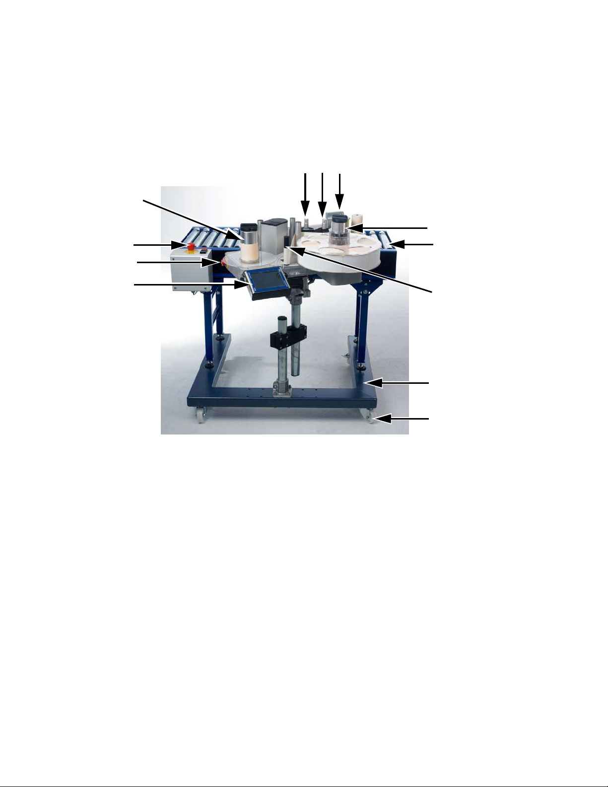
System Overview
Figure 3-1 shows the system overview of the Label Printer Applicator on a production line.
1
2 3
12
4
11
5
10
9
6
7
8
1.
Ribbon Supply Mandrel
2.
Ribbon Waste Mandrel
3.
Peel Tip
4.
Label Supply Mandrel
5.
Conveyor
6.
Dancer Arm
7.
Vertical Stand with Conveyor (U Base)
8.
Caster
9.
CLARiTY Display
10.
E-Stop Button (LPA)
11.
E-stop Button (Conveyor)
12.
Label Waste Mandrel
13.
Printhead*
*
Components are not shown in the figure
Figure 3-1: System Overview
The main parts of the LPA are:
•
CLARiTY Display
•
Labeller
•
Printhead
For more information on other integral parts of the LPA, refer to “Main Parts” chapter of
Operator Manual.
Page 28
CLARITY Display 3-3
ICE Vulcan Service Manual
The Vulcan is available with 115 mm label width with high speed 107 mm thermal transfer
printhead. The LPA is available in either left-handed or right-handed versions to suit different
configurations of the packaging line and can be oriented horizontally or vertically.
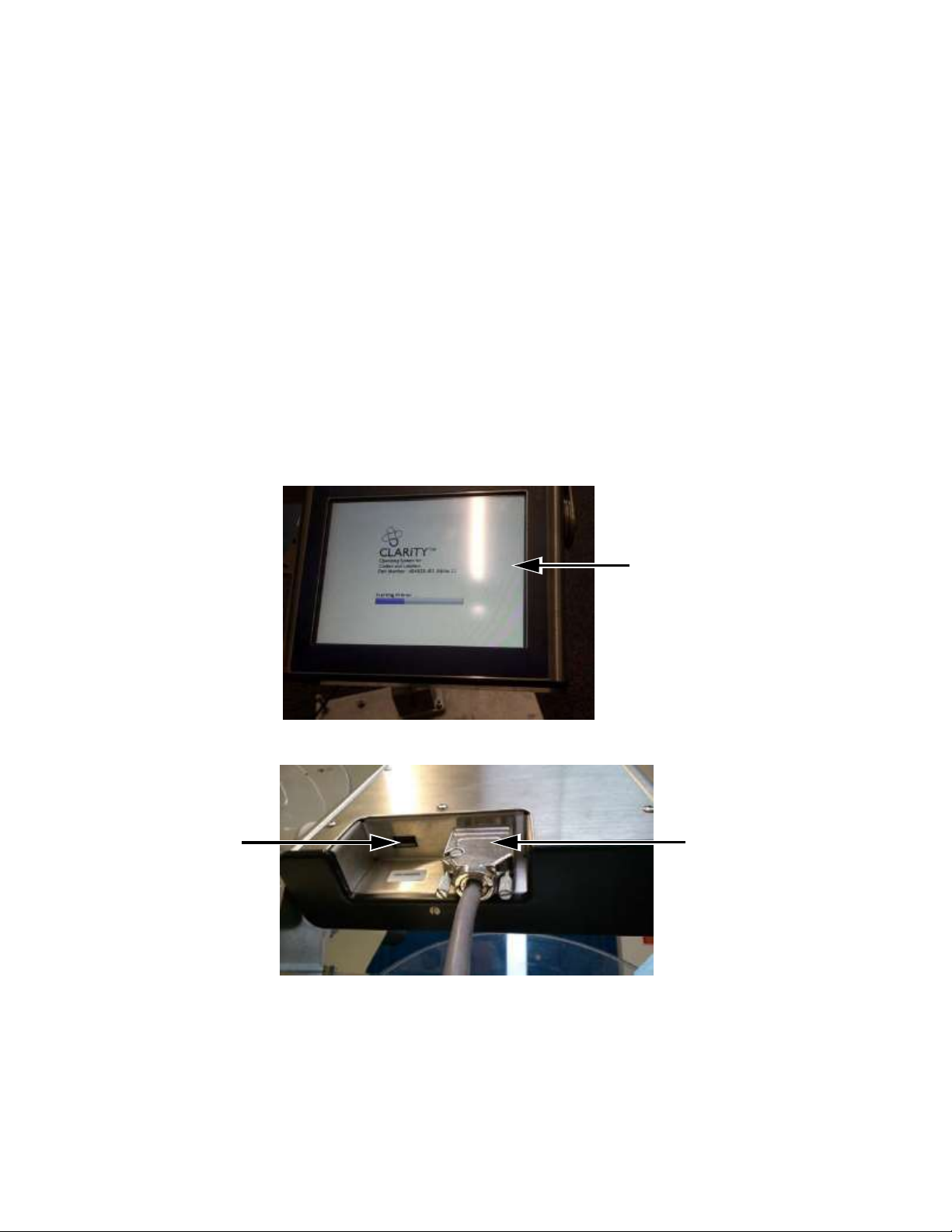
CLARITY Display
This display is a touch screen user interface connected to the main controller board via a
communication/power cable (see Figure 3-2).
The display has an LCD 6.5" display.
For more details on user interface, refer to “CLARiTY Operating System” on page 5-1.
1
3
2
1.
Touch UI
2.
Interconnecting Cable (Communications Cable)
3.
USB
Figure 3-2: Display Connections
Page 29
CLARITY Display 3-4
ICE Vulcan Service Manual
Caution
EQUIPMENT DAMAGE. The interconnecting cable must be connected in the correct
orientation to avoid damage to the LPA main board.
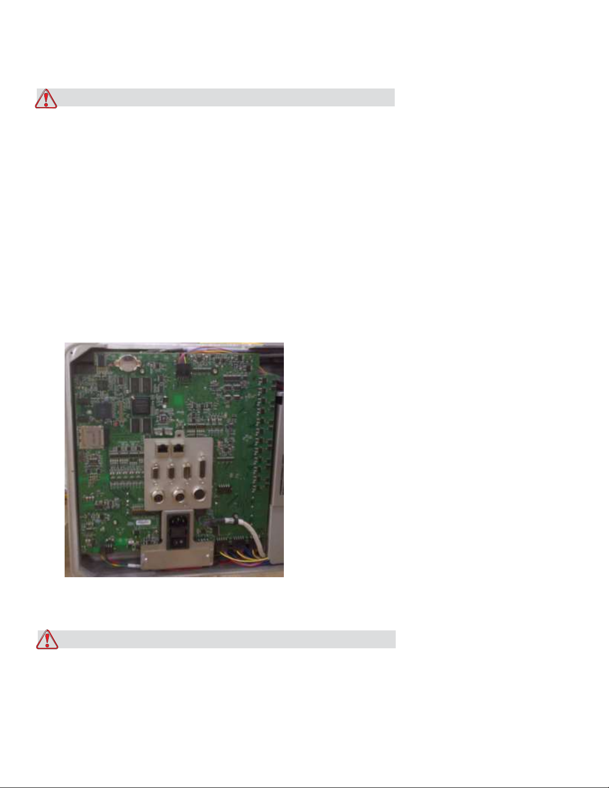
Labeller
The labeller consists of the following main parts:
Main Controller Board for the LPA
The main controller board is located behind the labeller unit. The connector panel is directly
mounted to the main controller board.
Figure 3-3: Main Controller Board
Caution
EQUIPMENT DAMAGE. Care must be taken during servicing and handling to ensure that the
connectors are not subjected to mechanical stress. This may damage the main controller
board.
Page 30

Labeller 3-5
ICE Vulcan Service Manual
Gap Sensor and Print Roller Sensor PCB
The gap sensor and print roller sensor PCB is located near the peel tip assembly.
Gap Sensor and Print
Roller PCB
Figure 3-4: Gap Sensor and Print Roller PCB
Ribbon and Printhead Sensor PCB
The ribbon and printhead sensor PCB is located near printhead assembly.
2
1.
Ribbon and Printhead Sensor PCB
2.
Motor Drive Cover Plate Removed
Figure 3-5: Ribbon and Printhead Sensor PCB
1
Page 31

Labeller 3-6
ICE Vulcan Service Manual
Label Drive Motor PCB
The label drive motor PCB is located near label drive motor.
2
1
1.
Label Drive Motor
2.
Label Drive Motor PCB with Protective Cover
Figure 3-6: Label Drive Motor PCB
CLARiTY Display PCB
The CLARiTY display PCB is located behind the LCD.
CLARiTY
Display PCB
Figure 3-7: CLARiTY Display PCB
Page 32

Labeller 3-7
ICE Vulcan Service Manual
Supply Reel Hall Sensor PCB
The supply reel hall sensor PCB is located beside the pulley in the brake belt assembly.
2
1
1.
Pulley Removed
2.
Supply Reel Hall Sensor PCB
Figure 3-8: Supply Reel Hall Sensor PCB
Dancer Arm Sensor PCB
The dancer arm sensor PCB is located below the pulley in the brake belt assembly.
1
2
1.
Pulley Removed
2.
Dancer Arm Sensor PCB
Page 33

Labeller 3-8
ICE Vulcan Service Manual
Figure 3-9: Dancer Arm Sensor PCB
Page 34

Labeller 3-9
Ports
Connectors
Description
Encoder
Port for connecting a shaft
encoder to the controller to tell
the software how fast the
substrate is traveling.
Serial Port
(IOIOI)
RS-232 Serial Port for connecting
to PC, PLC or other capable
device.
ICE Vulcan Service Manual
Connectors
The main controller board provides the following connections.
8
7
6
5
9
1
2
3
4
1.
Encoder
2.
Serial Port (IOIOI)
3.
Input / Output (I/O)
Figure 3-10: Connector
4.
Beacon
5.
Product Detect 2
6.
Product Detect
Table 3-1: Controller Connections
7.
8.
9.
CLARiTY Display
Ethernet
Ethernet POE
Page 35

Labeller 3-10
Ports
Connectors
Description
Input/Output
(I/O)
Port for connecting external
devices to the LPA’s hardware
inputs and outputs.
Beacon
Port for connecting external
beacon. For more details, refer
to the IPL chapter of Service
Manual.
Product Detect 2
Second product detector
connector is used for barcode
scanning.
Product Detect 1
The product detector connector
detects the product and informs
the LPA when to print and apply
the label on the product.
CLARiTY Display
Port for Communicating with
the CLARiTY Display and
provides power to it.
Ethernet
RJ-45 port for connecting the
printer to a TCP/IP network
Ethernet POE
RJ-45 port for connecting the
printer to a TCP/IP network
device that requires Power Over
Ethernet (POE) support.
ICE Vulcan Service Manual
Note: When an applicator is purchased then additional connector(s) are provided as required.
Table 3-1: Controller Connections (Continued)
Page 36

Rev AA
Encoder
Cable Pin
Wire Color
Function
1 1 Red
+24 V ENC
2 2 Black
0 V QENC
3 3 White
ENC AX
4 4 Green
ENC BX
5 5 - - 6 6 - - - 7 Link to Pin 8
Enc Present
- 8 Link to Pin 7
-
- 9 -
-
7
SHELL
BRAID SHIELD
CHASSIS
ICE Vulcan Service Manual
Pin Description for Connectors Encoder
Figure 3-11: Encoder Pin
Table 3-2: Encoder Pin
Page 37

Rev AA
Cable Pin (15 pos)
DSUB
Wire Color
(Alpha-Wire)
Function
1
Black
LINE SEL BCD0
2
White
LINE SEL BCD1
3
Red
LINE SEL BCD2
4
Green
LINE SEL BCD3 / LINE
INTERLOCK
5
Orange
LINE STROBE
6
Blue
IGNORE PACK
7
White/Black
0 V IO
8
Red/Black
+24 V APPL
9
Green/Black
LINE INT'LK COM
10
Orange/Black
LINE INT'LK N/C
11
Blue/Black
LINE INT'LK N/O
12
Black/White
REJECT OUT
13
Red/White
READY / BUSY OUT
14
Green/White
0 V
15
DRAIN WIRE
0 V
ICE Vulcan Service Manual
Input / Output
Figure 3-12: Input/Output
Table 3-3: Input/Output
Page 38

Labeller 3-12
Cable Pin
Wire Color
Function
1
Green
24 V, 50 mA, PNP
2
Yellow
Not connected
3
Red
24 V, 50 mA, PNP
4
Amber
24 V, 50 mA, PNP
5
Black
Not connected
6 - 0 V
Scanner
Cable Pin
Wire Color
Function
1 5 Brown
GND
2 9 Blue
+12 V DC
3 - -
-
ICE Vulcan Service Manual
Beacon
Figure 3-13: Beacon Pin
Table 3-4: Beacon Connection
Power Cable (RS232)
Figure 3-14: RS232 Connection
Table 3-5: RS232 Connection
Page 39

Labeller 3-13
Scanner
Cable Pin
Wire Color
Function
4 - - - 5 - -
-
6 2 Yellow
TXD (RS-232)
7 - -
-
8 - -
-
9 5 Red
SENS GND
10 4 Violet
SENSOR 1
11 - - - 12 3 Red/Blue
RXD (RS-232)
-
SHELL
BRAID SHIELD
CHASSIS
Sensor
Cable Pin
Wire Color
Function
1 1 Red
+24 V
2 - White
- 3 3
Black
0 V
4 4 Green
PNP OUTPUT
5 - White
-
6 - Blue
-
7
SHELL
DRAIN WIRE
CHASSIS
ICE Vulcan Service Manual
Table 3-5: RS232 Connection (Continued)
Product Detect
Figure 3-15: Product Detect Pin
Table 3-6: Product Detect Connection
Page 40

Labeller 3-14
ICE Vulcan Service Manual
Ribbon Web
Note: In Direct Thermal applications, the ribbon web is not required.
The ribbon is routed from the ribbon supply mandrel, through the printhead to the ribbon
waste mandrel. This forms the ribbon web.
Ribbon Supply Mandrel (Black disc)
The ribbon supply mandrel (with black disc) holds the ribbon, that is
pre-coated with ink. During printing, the ribbon is supplied to the thermal printhead where the
ink is applied onto the labels.
1
2
1.
Ribbon Waste Mandrel
2.
Ribbon Supply Mandrel
Figure 3-16: Ribbon Mandrels
Page 41

Labeller 3-15
ICE Vulcan Service Manual
Ribbon Waste Mandrel
The ribbon waste mandrel collects the waste ribbon that remains after the label has been
printed.
The waste ribbon can be easily removed by using the pullout shaft in the ribbon waste
mandrel which allows the core to be easily removed.
1
2
1.
Pullout Shaft
2.
Ribbon Waste Mandrel
Figure 3-17: Ribbon Mandrels
Page 42

Labeller 3-16
ICE Vulcan Service Manual
Label Web
The labels are routed from the label supply mandrel, through the printhead assembly to the
label waste mandrel. This forms the label web.
Label Supply Mandrel
The label supply disc holds the label roll in place on the mandrel. The mandrel lock is used to
retain the roll in place. The mandrel lock indicates the locking and unlocking directions.
1
2
1.
Mandrel Lock
2.
Label Supply Disc
Figure 3-18: Label Supply Mandrel
Dancer Arm
The dancer arm is designed to absorb the change in tension of the label web, during its
movement through the LPA.
1
2
1.
2.
Dancer Arm
Dancer Arm Roller
Figure 3-19: Dancer Arm
Page 43

Labeller 3-17
ICE Vulcan Service Manual
Idler rollers
The idler rollers are free-spinning rollers that support and guide the label web through the
LPA. The position of the rollers is set for optimum feeding of the label web.
Idler Rollers
Idler Rollers
Figure 3-20: Idler Rollers
Label Waste Mandrel
The label waste mandrel winds the empty label backing (waste) that remains after the label
has been printed and applied on the product. The mandrel lock is used to hold and retain the
roll in place and allows easy removal of the waste roll. The mandrel lock indicates the locking
and unlocking directions.
Mandrel Lock
Figure 3-21: Label Waste Mandrel
Page 44

Labeller 3-18
ICE Vulcan Service Manual
Emergency Stop (E-Stop)
Warning
PERSONAL INJURY. The LPA has exposed rotating parts. Keep hands, long hair, ties, loose
clothing and so on away from the machine at all times, when it is switched on. Do not wear
jewelry,
e.g. ear or finger rings, while working with the equipment.
In case of emergency, the LPA can be stopped immediately by pressing the E-Stop button.
When the E-Stop button is pressed, power to the label drive is removed and the LPA is
stopped. A fault message is displayed.
The E-Stop button is fitted on the side wall of the machine (see Figure 3-22).
E-stop button
Figure 3-22: Emergency Stop Button Position
The E-Stop is reset by pulling out the E-Stop button. However, the LPA will remain in fault
mode until the fault message is cleared.
Note: The E-Stop for the LPA will not stop the conveyor. It is only for the LPA operation.
Page 45

Labeller 3-19
ICE Vulcan Service Manual
The warning label for moving parts is attached on the face of the baseplate of the machine.
Figure 3-23: Moving Parts Warning Label
Warning
PERSONAL INJURY. Do not, under any circumstances, remove or obstruct any warning, caution,
or instruction labels present on the equipment. If any part of these labels become damaged,
worn or removed they must be immediately replaced.
Sensors
The LPA is equipped with the following sensors to ensure correct operation
of the system without manual intervention.
Label Gap Sensor
The label gap sensor detects the gap between each label. The LED (item 2,
Figure 3-24) displays the status of the sensor. Refer to “LED Indicator
Description” on page 6-17.
1
2
1.
Label Gap Sensor
2.
LED
Figure 3-24: Label Gap Sensor
Page 46

ICE Vulcan Service Manual
Printhead
The printhead is equipped with a series of very small, densely clustered
heating elements (dots) mounted on a ceramic substrate. When electrical
current is supplied to the dots, they get heated rapidly.
Thermal Transfer Print melts the ink on the ribbon. The ink deposits on
the label, and quickly dries after the label leaves the printhead.
In Direct Thermal, the color change of the label is directly caused by the
heating elements without ribbon.
4
1
3
1.
Ribbon
2.
Label
3.
LED
4.
Printhead
Figure 3-25: Printhead
For the printing theories, refer to Appendix D, “Theory Of Printing”.
2
Page 47

ICE Vulcan Service Manual
Installation
This chapter contains the following topics:
•
Tools and Supplies
•
Unpacking and inspecting the labeller
•
Selection of a suitable installation position
•
Installing the label applicator
Caution
EQUIPMENT DAMAGE. Only ICE trained personnel must carry out the installation and
maintenance work. Any such work undertaken by unauthorized personnel can damage the
LPA and invalidate the warranty.
Warning
PERSONAL INJURY. Make sure that the mains electrical supply is within the range indicated by
the label adjacent to the mains inlet of the labeller. If the voltage ratings differ, do not use the
labeller until you consult your ICE supplier.
Use only the mains power cable supplied with the labeller. This cable must terminate in an
approved, three-pole, mains plug which has a protective ground conductor.
Keep electrical power cables, sockets and plugs clean and dry at all times.
Page 48

Warning
4-2
ICE Vulcan Service Manual
PERSONAL INJURY. The labeller must be connected to an AC power supply, which has a
protective ground conductor in accordance with IEC requirements or applicable local
regulations. Any interruption of the protective ground conductor or disconnection to the
protective ground terminal may render the apparatus dangerous.
Warning
PERSONAL INJURY. Lethal voltages are present within this equipment when it is connected to
the mains electrical supply. Observe all statutory electrical safety codes and practices. Unless
it is necessary to run the labeller, disconnect the labeller from the mains electrical supply
before removing the covers, or attempting any service or repair activity. The failure to follow
this warning can cause death or personal injury.
Warning
PERSONAL INJURY.The LPA and stand components are heavy. Exercise proper lifting
precautions when removing components from their packaging, and during assembly.
Caution
EQUIPMENT DAMAGE. Take care when manipulating the Vulcan and stand components.
Tighten all fittings securely.
Page 49

Warning
4-2
ICE Vulcan Service Manual
Tools and Supplies
Tools
•
Allen Wrenches
•
Adjustable wrench
•
Level
•
Ruler
Supplies
•
Ribbon Roll
•
Label Roll
•
Gloves
•
Tissue
Unpacking and Inspecting the Labeller
Open the shipping box. Inspect the parts, if any part is missing or damaged, contact ICE at
01159 640144
Refer to Chapter 7, “Illustrated Parts List” for part numbers.
Selection of a Suitable Installation Position
The LPA is available to print and apply labels in Right Hand or Left Hand directions and can be
mounted vertically or horizontally. Choose a suitable installation position based on the
mounting requirement of the customer.
When choosing a suitable installation position for the labeller on the line, make sure that it is
possible to replace the labels and ribbons easily, and the emergency stop and mains plug are
easily accessible.
Page 50

Warning
4-4 Selection of a Suitable Installation Position
ICE Vulcan Service Manual
PERSONAL INJURY. Risk of injury to hands from moving machine parts. When selecting the
installation position, make sure that the labels and ribbons can be replaced at any time
without any danger.
Caution
EQUIPMENT DAMAGE. Select an installation position to avoid vibrations on the printhead,
electrostatic charge and soiling caused by lacquer, adhesive or other similar products used in
the production process.
Warning
PERSONAL INJURY. The mains plug must remain accessible at all times, because it serves as the
main power disconnect.
Positioning of Labeller/Peel Tip
Identify a suitable position for the LPA according to the required product direction and the
type of applicator module used. Refer to the appropriate Applicator Addendum for details on
the applicators.
Note: Direct apply applicator is fitted on the standard LPA unit.
Page 51

Installing the Label Applicator 4-6
ICE Vulcan Service Manual
Installing the Label Applicator
The following procedure explains the installation of the Vulcan Label Applicator on a
production line.
Assembling the Stand
Do the following procedure to assemble the Stand.
Note: This procedure explains a typical horizontal left hand configuration. A different
configuration may require a different stand. Make sure the installation is completed as per the
requirement.
Note: Additional stand instructions are available for different configurations.
1
Remove the stand from the packaging in an area with sufficient room to build the stand
close to the final production location.
Page 52

Installing the Label Applicator 4-7
ICE Vulcan Service Manual
2
Place the base (item 5, Figure 4-1) onto the floor and secure in place by locking the casters
(item 1, Figure 4-2) and lowering the additional feet (item 2, Figure 4-2) into position.
Note: Do not over torque the locking bolts. The stand will need to be adjusted later when the
equipment is aligned to the conveyor.
1
7
2
6
5
4
1.
Mounting Fixture
2.
Casters (X4)
3.
Vertical Stand Fixing Location
4.
Feet (X4)
3
5.
Base
6.
M6 Nuts (X4)
7.
Stand
Figure 4-1:Horizontal Stand (H Base)
Page 53

Installing the Label Applicator 4-8
ICE Vulcan Service Manual
2 1
1.
Caster
2.
Feet
Figure 4-2:Caster and Feet
Page 54

Installing the Label Applicator 4-9
ICE Vulcan Service Manual
Warning
PERSONAL INJURY. The Steps from 3 to 9 require two persons to execute the actions.
3
Place the stand in position on the base (see Figure 4-3) and secure it using four M6 bolts,
washers and nuts (item 6, Figure 4-1 on page 4-6).
Figure 4-3:Horizontal Stand Location on H Base
Warning
There is only one location for the stand as shown in Figure 4-3. The LPA must be contained
within the H base footprint as shown in Figure 4-4 on page 4-8.
Note: Refer to the Stand Instructions for more information.
Page 55

Installing the Label Applicator 4-10
ICE Vulcan Service Manual
4
Adjust the mounting fixture (item 1, Figure 4-1 on page 4-6) to be centred over the
centre of the H base.
1
2
3
1.
H Base
2.
LPA
3.
Indicates Containment Area
Figure 4-4:LPA Contained Within H Base Footprint
Warning
PERSONAL INJURY. Ensure that the stand has been assembled correctly and is secure (i.e.
casters locked) before mounting the LPA to the stand.
Warning
PERSONAL INJURY. Follow the instructions on constructing the stands and mounting the LPA.
Page 56

Installing the Label Applicator 4-11
ICE Vulcan Service Manual
Mounting the LPA
Warning
PERSONAL INJURY. Follow manual handling guidelines when moving equipment and
loading labels.
5
Mount the two stand bars (item 4, Figure 4-5) to the LPA base (item 1).
There are three locations (item 2) on the LPA base to mount stand bars, choose the most
appropriate locations for horizontal mounting.
4
1.
LPA Base
2.
Location to Mount Stand Bars (X3)
3.
M8 Screws (X2)
4.
Stand Bars (X2)
Figure 4-5:LPA Base
1
2
3
Page 57

4-10 Installing the Label Applicator
ICE Vulcan Service Manual
6
Secure the stand bars (item 2, Figure 4-6) with the M6 grub screws (item 1).
Note: It is recommended not to fully tighten the grub screws to allow some movement of the
stand bars whilst locating to the stand.
2
1
1.
M6 Grub Screws
2.
Stand Bar
Figure 4-6:Stand Bar and Grub Screw
7
Place the LPA stand bars along with the LPA to the mounting fixture
ensuring that the LPA is within the correct footprint as shown in Figure 44 on page 4-8. Secure it by tightening the M8 screws (item 3, Figure 4-5
on page 4-9).
8
Tighten the M6 grub screws (item 1, Figure 4-6) on the LPA.
9
When the LPA is secure in place, raise the feet and unlock the casters.
Move the stand and LPA into position on the production line.
Note: It is not recommended to transport the unit over long distances.
Warning
PERSONAL INJURY. Ensure that the unit is pushed by two or more persons.
10
Secure the stand in position by locking the casters and lowering the
feet.
11
If necessary rotate the mounting fixture to place the LPA in the correct
location.
Page 58

4-10 Installing the Label Applicator
ICE Vulcan Service Manual
Setting up the Production Line
12
Position the label applicator and the stand adjacent to the conveyor.
Use the height adjustments on the stand to position the printhead and the
peel tip so that the label will be applied at the correct vertical location on the
box.
Figure 4-7: Labeller on Line
Page 59

Installing the Label Applicator 4-12
ICE Vulcan Service Manual
LPA
13
Using a level, check that both the conveyor belt and the
label applicator are close to “perfect horizontal alignment’ as
possible. Make adjustments if necessary.
Conveyor
Peel Tip
Figure 4-8: Level Check
14
Visually check to ensure that the plane of the peel tip runs
perfectly parallel to the side of the box.
Figure 4-9: Peel Tip Alignment
15
Use the leveling feet to make any fine adjustments to the
angle between the peel tip and the side of the box.
Otherwise, use the leveling feet to secure the LPA and stand in
Page 60

Installing the Label Applicator 4-13
ICE Vulcan Service Manual
place. Use an adjustable wrench.
Page 61

Installing the Label Applicator 4-14
ICE Vulcan Service Manual
Mounting the CLARiTY Display
16
Fix the CLARiTY display bracket to the labeller using the 3 mm
allen wrench and two M3 screws.
CLARiTY Display Bracket
Figure 4-10: CLARiTY Display Bracket
Warning
PERSONAL INJURY. The CLARiTY display should be mounted in a convenient location to
eliminate the potential entanglement with the exposed rotating parts.
17
Mount the CLARiTY display on the bracket using the two button
head screws with washers and metal washers.
1
2
1.
Button Head Screw with Washer (x2)
2.
Metal Washer (x2)
Figure 4-11: CLARiTY Display
Page 62

Installing the Label Applicator 4-15
ICE Vulcan Service Manual
Instating the Product Detector
18
the label applicator.
Note: Position the product detector as needed for the application and
the production line.
Figure 4-12: Product Detector
19
on the side of the applicator.
Mount the product detector to the conveyor, upstream of
Product
Detector
Connect the external shaft encoder (if used) to the DB-9 port
Page 63

Installing the Label Applicator 4-16
ICE Vulcan Service Manual
Cable Connections
20
Make the cable connections as shown in Figure 4-13 and Figure
4-14 on page 4-16.
1.
Beacon
2.
Mains Power Lead
Figure 4-13: Cable Connections
4
3
2 1
3.
4.
Product Detect 2
CLARiTY Display
Page 64

Installing the Label Applicator 4-17
ICE Vulcan Service Manual
Note: Make sure the mains switch is turned off before connecting cables.
Note: Two identical product detector connectors are available. Make sure that the product
detector connector is plugged into the ‘Product Detect 1’ port.
Note: Do not place excessive strain on the beacon cable before mounting the beacon.
Display
TCP/IP
Network
TCP/IP
Network with
PoE
RS-232 Connection
External Device I/O
Beacon
Barcode Scanner
Encoder
Product Detect Sensor
Figure 4-14: Wiring Connection
Page 65

Installing the Label Applicator 4-18
ICE Vulcan Service Manual
Loading the Web
Loading the web involves following procedures:
•
Loading a label roll on to the label supply disc mandrel
•
Loading a ribbon roll on to the ribbon supply mandrel
D
C B
A.
Gap Sensor
B.
Peel Tip
C.
Ribbon
D.
Label
Figure 4-15: Left Hand Webbing Diagram
D
C
B
A.
Gap Sensor*
B.
C.
A
Peel Tip
Ribbon
D.
Label
*- Items not shown in picture
Page 66

Installing the Label Applicator 4-19
ICE Vulcan Service Manual
Figure 4-16: Right Hand Webbing Diagram
Page 67

Installing the Label Applicator 4-20
ICE Vulcan Service Manual
Loading a Label Roll on to the Label Supply Disc Mandrel
Warning
PERSONAL INJURY. Follow manual handling guidelines when moving equipment and
loading labels.
21
Unlock the mandrel lock in the direction indicated on the lock
on the supply mandrel (see Figure 4-17). Remove the label supply
disc.
Unlock
Lock
Note: Left Hand unit shown
Figure 4-17: Mandrel Lock
22
Fit the label roll to the label supply mandrel. Ensure that the
label supply is placed onto the mandrel so that the labels feed in
the direction indicated on the supply disc.
1
2
1.
Label Supply Mandrel
2.
Label Supply
Figure 4-18: Label Web Path
Page 68

Installing the Label Applicator 4-21
ICE Vulcan Service Manual
23
the label supply mandrel lock by turning the lock to the locked position
as indicated on the mandrel lock (see Figure 4-17).
24
the label routing. Thread the label web as shown in Figure 4-15 on page
4-17 and Figure 4-16 on page 4-17 (i.e, route the labels around each of
the rollers in turn as shown on the webbing diagram).
Ensure that the labels are threaded through the label gap sensor and
around the peel tip.
3 2
If the unit is vertical, replace the label supply disc and secure it with
Remove a number of labels from the beginning of the roll to support
1
1.
Label Around Peel Tip
2.
Label Gap Sensor
3.
Label
Figure 4-19: Label Around Peel Tip
25
Unlock the waste mandrel by rotating it in the direction indicated on
the mandrel lock. (see Figure 4-20).
Note: Left Hand unit shown
Figure 4-20: Waste Mandrel Lock
Page 69

4-20 Installing the Label Applicator
ICE Vulcan Service Manual
26
Secure the waste label backing to the waste mandrel by slotting
the backing into the slot as indicated by the arrows on the waste
mandrel.
Mandrel Lock
Note: Right Hand unit shown
Figure 4-21: Mandrel Slot
27
Secure with the mandrel lock (a click sound is audible when
secured) and wind the label web around the mandrel two or three
times until the label web is secure.
Note: If the mandrel lock is not secured, the label speed will not be
accurate.
28
Place the supply disc on the supply mandrel and lock it if not
already completed.
For information on removing the ribbon and labels from the LPA,
refer to “How to Replace Label and Ribbon Web” on page 6-30.
Loading a Ribbon Roll on to the Ribbon Supply Mandrel
29
Remove the new ribbon from its packaging.
30
Unwind approximately 300 mm of ribbon from the reel (an
initial length of the ribbon is ink free and is termed 'leader').
31
Fit the new ribbon to the supply mandrel, and ensure that the
reel is pushed fully onto the mandrel.
Page 70

4-20 Installing the Label Applicator
ICE Vulcan Service Manual
32
not routed below the gap sensor (see Figure 4-22).
3
Thread the ribbon around the printhead, ensuring that the ribbon is
1
2
1.
2.
3.
Printhead
Gap Sensor
Ribbon Supply (Ink Side Down)
Figure 4-22: Loading Ribbon Around Printhead
Note: Ensure that the ink side of the ribbon is facing the label after the ribbon
is routed through the printhead.
Refer to the webbing diagram for the correct web path (see Figure 4-15 on
page 4-17 and Figure 4-16 on page 4-17).
33
Load the fresh waste core onto the waste mandrel and ensure that
the ribbon runs in the direction of the mandrel arrow.
Page 71

Installing the Label Applicator 4-22
ICE Vulcan Service Manual
34
Secure the ribbon to the waste mandrel with an adhesive
tape to prevent from slipping.
Note: Make sure that the pullout shaft is in required position.
1
2
1.
Pullout Shaft
2.
Waste Ribbon Mandrel
Figure 4-23: Pullout Shaft
35
Wind excess ribbon onto the waste mandrel, ensuring that the
ribbon is not torn or wrinkled.
1
4
2
3
1.
Ribbon Waste Mandrel
2.
Printhead
3.
Ribbon Supply (Ink Side Down)
4.
Ribbon Supply Mandrel
Figure 4-24: Loading Ribbon Around Printhead
Caution
EQUIPMENT DAMAGE. Turn the waste mandrel only to provide tension in the ribbon.
Page 72

Installing the Label Applicator 4-23
ICE Vulcan Service Manual
Turning On the Machine
36
Switch on the power switch on the rear of the unit.
Power Switch
Figure 4-25: Power Switch
37
CLARiTY Display will power on.
Figure 4-26: CLARiTY Display Power On
Setting up the User Interface
38
In the CLARiTY Display, navigate to Tools > Setup >
Control > Installation Wizard. The Installation Wizard dialog box
appears.
39
Follow the on-screen instructions provided by the Installation
Wizard and touch Next when ready to progress. For information on
Installation Wizard, refer to Operator Manual.
In case of an error, touch Back to return to the previous screen and
Page 73

Installing the Label Applicator 4-24
ICE Vulcan Service Manual
correct the error. Touch Cancel to exit from the wizard.
Page 74

Installing the Label Applicator 4-25
ICE Vulcan Service Manual
Refer to the Operator Manual for setting up the LPA using the installation wizard.
Note: Parameters altered when running through the installation wizard are saved on
selection. Selecting ‘Cancel’ will exit the user from the wizard, it will not reset any parameter
to the previous value.
Note: If the LPA is setup offline to confirm operation, it may be necessary to restart the
installation wizard to ensure that the online setup is correct.
Page 75

Getting started with the CLARiTY 5-1
ICE Vulcan Service Manual
Clarity Operating system
This chapter contains the following topics:
•
Getting started with the CLARiTY
•
How to configure the LPA
•
How to set the external outputs
•
Critical settings
•
Working with passwords
•
CLARiTY power saving
•
How to configure job settings
•
Managing Clones
For more information on the user interface, refer to Operator Manual.
Getting started with the CLARiTY
CLARiTY is an icon-based operator control system. It has an easy-to-use touch screen and most
areas of the display are active, that is, touching an area on the screen is like pressing a button on
a traditional control panel. All technical aspects of the LPA setup and control are accessed
through the Tools button.
Page 76

Getting started with the CLARiTY 5-2
ICE Vulcan Service Manual
Figure 5-1 shows the home screen of the CLARiTY operator system.
Using the Home Page
11
1
11
2
3
4
10
5
9
8
6
7
1.
2.
3.
4.
5.
6.
Status Bar
Tools Button
Current Job Details Bar
Consumables
Ribbon
Labels
7.
8.
9.
10.
11.
12.
Print Position
Performance Information
Print Button
System Control Buttons
Home Button
Job Select Button
Figure 5-1: CLARiTY Home Page
Warning
PERSONAL INJURY. The LPA starts printing if you touch the status bar when the LPA is in OFFLINE
mode. Make sure that you do not touch the status bar if the LPA is not required to run.
Page 77

Getting started with the CLARiTY 5-3
ICE Vulcan Service Manual
Buttons
Description
Status Bar
Provides information about the status of the
LPA.
•
Running: LPA is on and ready to print
when the proper print trigger is received.
•
Offline: LPA is on and not printing.
•
Shutdown: Power to the
printhead is disabled and not
printing.
•
Warning: Conditions exist that the
Operator should be aware of, but do not
keep the system from printing.
•
Fault: Conditions exist to keep the
system from printing.
•
Allows the user to toggle between
offline and running mode, enabling or
disabling printing.
•
Allows the user to access the current
warning and fault screens if any
present.
Tools Button
Opens the Tools menu when selected.
Current Job Details
Page
Displays the information about the current
job and when selected, opens the current
job details screen.
Consumables
Displays the Consumables page showing
labels and ribbon information.
Table 5-1: Home Page
Page 78

Getting started with the CLARiTY 5-4
ICE Vulcan Service Manual
Buttons
Description
Labels
Displays the following label information (user
can also access Labels page by navigating to
Consumables > Labels):
•
Percentage: Percentage of label available
•
Estimated Empty Time: Estimated time by
when the label will empty based on the
current job and the production rate.
•
Estimated Time Remaining: Estimated time
remaining based on the current job and the
production rate.
•
Last Changed: Date and time when the
label was last changed.
Table 5-1: Home Page (Continued)
Page 79

Getting started with the CLARiTY 5-5
ICE Vulcan Service Manual
Buttons
Description
Ribbon
Displays the following ribbon information (user can also access Ribbon
page by navigating to Consumables > Ribbon):
•
Percentage: Percentage of ribbon available
•
Estimated Empty Time: Estimated time by when the ribbon will empty based on
the current job and the production rate.
•
Estimated Time Remaining: Estimated time remaining based on the current job
and the production rate.
•
Last Changed: Date and time when the ribbon was last changed.
Print
Position
Opens the Print Position menu when selected. Permits the user to set the label
position on the product, print position X and print position Y on the label. For more
information, refer to the Operator Manual.
Table 5-1: Home Page (Continued)
Page 80

Rev AA
How to Configure the LPA 5-6
ICE Vulcan Service Manual
Buttons
Description
Performance
Information
Displays the following LPA
performance information:
•
Throughput: Throughput of the LPA in
prints per minute since the current Job was
loaded.
•
Batch Count: Number of prints since
the current Job was loaded.
•
Total Count: Number of prints over the
life of the LPA.
Selecting this area opens the performance
page showing additional statistical
information on the LPA throughput. For
more information, refer to the Operator
Manual.
Print Button
Permits the user to print a test
image on selection.
Note: This option is only present if
option is enabled on the printer using
CLARiTY Configuration Manager.
System Control Buttons
Permits the user to switch off or switch
on the LPA. It also allows the user to
change the LPA between RUNNING and
OFFLINE modes.
Home Button
Returns the user to the Home screen as
shown in Figure 5-1 on page 5-2.
Job Select Button
Permits the user to select the required
job from the list. For more information,
refer to the Operator Manual.
Table 5-1: Home Page (Continued)
How to Configure the LPA
CLARiTY Configuration Manager
As coding and labelling equipment have become increasingly versatile and flexible with a
wide range of applications, the number of variables that can be configured within a LPA has
become very large. Although LPAs are pre-programmed with default values, as the extent of
Page 81

Rev AA
How to Configure the LPA 5-7
ICE Vulcan Service Manual
the application increases, it becomes less likely that the default configuration is ideal. This can
lead to a large and cumbersome menu tree on the LPA’s user interface that users have to
work with.
Most LPA variables are set during the installation process. The variables are set to values that
tailor the LPA to the application. Once set, these variables only need to be changed when the
application for the LPA changes.
Page 82

Rev AA
How to Configure the LPA 5-8
ICE Vulcan Service Manual
As such, these installation parameters are set through a configuration programme called
CLARiTY Configuration Manager.
The CLARiTY Configuration Manager (Figure 5-2) is a PC software program, that provides the
following basic features:
•
Setting of the LPA variables
•
Saving/retrieving a set of variable values to a PC file for later/ repeated use
•
Downloading a set of variables to the LPA's CLARiTY user interface for non-volatile
(permanent) memory storage in the LPA
•
Uploading a set of variables from the LPA for review/comparison/ modification
•
Updating the system software
•
Saving/retrieving language files
•
Saving/retrieving job, font, and graphics files
•
Snapshot of CLARiTY screens
Figure 5-2: CLARiTY Configuration Manager
As a result, the CLARiTY user interface retains the availability of a small number of operating
variables for the user to change.
It also provides an increased level of LPA system integrity, because the configuration
variables cannot be accessed from the LPA itself, but from a connected PC.
If the LPA is installed to run in a standalone mode (i.e., the LPA is not connected to network),
the PC is only linked briefly (via the RS232 serial or ethernet port) for the period of
upload/download of the variables (a few seconds). The PC would then be removed.
Page 83

Rev AA
How to Configure the LPA 5-9
ICE Vulcan Service Manual
In a networked environment, system administrators could have direct access to the LPA, while
line operators are limited to accessing only the operating variables that are relevant to them.
How to Install the CLARiTY Configuration Manager
CLARiTY Configuration Manager is available in the CD with the Operator Manual. To operate
the CD, the system requires Windows XP, NT or Windows 7.0 operating system with minimum
5 MB capacity and ethernet or serial port. The installation routine commences automatically.
Do the following tasks to install:
1
Insert the CD.
2
Click on the CD drive.
3
Select CLARiTY Configuration Manager on the CD Index. File Downloads page
appears.
4
Run the CLARiTYConfig.exe file.
Follow the on-screen instructions to install the software. The software is installed in the PC
and is ready for use.
How to Connect the CLARiTY Configuration Manager to the LPA
Note: When you connect the CLARiTY Configuration Manager to the LPA, the first connection
must be done using an RS232 connection.
How to Connect the CLARiTY Configuration Manager to the LPA using an RS232 connection
Do the following tasks to connect the CLARiTY Configuration Manager to the LPA:
1
Connect the PC serial port to the main controller board using the null- modem cable.
2
Ensure that all other programs (such as, Active sync and other PDA applications) that use
the serial port are disabled.
Page 84

Rev AA
How to Configure the LPA 5-10
ICE Vulcan Service Manual
3
Run the CLARiTY Configuration Manager on the PC (Figure 5-3).
Status Panel
Figure 5-3: CLARiTY Configuration Manager
4
Ensure that the LPA status panel (at the bottom left of the window) reports the message
"Connection Active" and the new printer icon turns green.
If the status displays "Not connected", disable or quit the other applications running on the
PC that are using the serial port. Check that the baud rate settings on the Configuration
Manager matches with the LPA’s baud rate.
5
Click the Upload button (see Figure 5-4). The progress of the operation is displayed in the
status panel. This uploads the LPA parameters set to the PC.
Page 85

5-10 How to Configure the LPA
Rev AA
ICE Vulcan Service Manual
The list of folders containing the configuration parameters appears in the parameter listing (in
the right hand frame of the Configuration Manager).
Figure 5-4: CLARiTY Configuration Manager
Note: It is possible to setup the IP address using the CLARiTY user interface Archive feature with
USB. Refer to “Creating, Editing and Restoring a USB Archive on a CLARiTY LPA” on page 5-17.
How to Connect the CLARiTY Configuration Manager to the LPA using an Ethernet cable
The following components are required to connect the LPA to CLARiTY Configuration
Manager via Ethernet cable:
•
Correct Ethernet cable
-
If connection is being made directly between the PC and the LPA, a crossed Ethernet cable
must be used.
-
If the connection is being made via an office LAN or Ethernet hub, an ordinary uncrossed
patch cable is used.
•
Correct configuration of the PC ethernet port
•
Correct configuration of the LPA’s ethernet port
Page 86

5-10 How to Configure the LPA
Rev AA
ICE Vulcan Service Manual
To connect the CLARiTY Configuration Manager to the LPA, the following settings have to be
done on the PC ethernet port and LPA’s ethernet port:
PC
The PC Ethernet port must be set up to connect at a specific IP address. If you are connecting
via an office LAN, consult with your IT manager before assigning IP addresses to your PC. If
you are making a direct connection, you may specify any IP address.
1
Open the PC Ethernet port properties and select Use the following IP address. Then
specify the new address (for example: 10.27.55.130 in Figure 5-5) and the subnet mask
(Usually 255.255.255.0).
Figure 5-5: IP Address Settings on the PC
Note: The screen above shown varies depending on the operating system installed on your PC.
2
Click OK to apply the settings.
Page 87

Rev AA
How to Configure the LPA 5-12
ICE Vulcan Service Manual
LPA (Coder) Ethernet Port
3
Locate the TCP/IP configuration parameters as shown in Figure 5-6.
Set the IP Address
Figure 5-6: TCP/IP Configuration Parameters
4
Set the BinaryCommsNetworkPort parameter to 3001.
5
Set the IP address to be in the same range as the PC port
(for example: 10.27.55.131 in Figure 5-5 on page 5-11) and click Apply.
Note: The LPA IP address should not be the same as the IP address of the PC.
6
Set the Subnet mask to match that of your PC port.
7
Right-click on the New Coder 1 icon and click the Download button to download the
parameters to the LPA.
Page 88

Rev AA
How to Configure the LPA 5-13
ICE Vulcan Service Manual
8
Click the New Coder1 icon and change the method of connection to Network. Enter the
correct IP address and Port number to match the values downloaded into the LPA.
Figure 5-7: New Coder Settings
9
Click the Apply button and the new settings are activated and the coder icon turns
green.
10
Click the Upload button. The progress of the operation is displayed in the status panel.
This uploads the LPA parameters set to the PC.
The list of folders containing the configuration parameters appears in the parameter listing (in
the right hand frame of the Configuration Manager).
Page 89

Rev AA
How to Configure the LPA 5-14
ICE Vulcan Service Manual
How to Edit the Parameters
Figure 5-8 displays the list of parameters that are available in the LPA settings.
Parameters List
Figure 5-8: Parameters
Click the folder required to open or close it or to gain access to the parameters it contains.
You may have to click and open a number of nested folders to get to the parameter that you
want.
There are a number of different types of parameters. Click Help on the menu at the top of the
screen, and select Key To Legends to get a list of the different icons/parameter types.
Do the following tasks to change the value of a parameter:
1
Click the required parameter from the parameter list. The current value is displayed in
the Value box at the bottom of the screen.
2
Change the value to the required value using the mouse and the keyboard.
3
Click the Apply button. The value displayed in the parameters list is updated to reflect
the change.
Note: Event parameters do not have values that can be set. Touching the Trigger button that is
available in the bottom pane causes the LPA to perform the given action on download.
Note: The list of configurable parameters for the LPA are shown in Appendix B, “CLARiTY
Configuration Manager”.
For many parameters, it may be satisfactory to leave them with their default values. Some of
the parameters may need tuning after some initial
Page 90

Rev AA
How to Configure the LPA 5-15
ICE Vulcan Service Manual
prints have been made. Some of the listed parameters are available at the CLARiTY panel. It
may be more convenient to make final adjustments at the panel rather than using the
CLARiTY Configuration Manager.
CLARiTY Configuration Manager has a default administrative password. This protects certain
parameters from change. To change the administrative password navigate to Advanced
passwords > Change Admin Password. The Default password is ‘password’.
Figure 5-9: CLARiTY Change Password
How to Save the Changes in the LPA
Do the following tasks to make the changes effective:
1
Click the Printer icon in the left-hand pane to open the LPA controls at the bottom pane of
the window.
2
Click the Download button to update the LPA with the changes that you have made to
the parameters.
A dialog box opens with the message “The parameters to be downloaded have not been
saved to an archive”.
3
Touch OK to continue with the download.
The new parameters are active when the download is complete.
Note: Unless steps 1 to 3 are performed, none of the parameter changes become effective in
the LPA.
Page 91

Rev AA
How to Configure the LPA 5-16
ICE Vulcan Service Manual
How to Save the User Password changes in the LPA
Do the following tasks to make the changes effective:
1
Click the Printer icon in the left-hand pane to open the LPA controls at the bottom pane of
the window.
2
Either select ‘Update Passwords on Download’ to update the passwords when changes are
downloaded to the LPA or select ‘Update Passwords’ to update the passwords only.
Figure 5-10: CLARiTY Save Password Change
How to Archive the Current Parameters
The set of parameters can also be saved as an archive and are stored on the PC. The archive
can be loaded into the Configuration Manager and downloaded to the LPA again at a later
date to revert to the archived set of parameters.
Once the LPA has been configured, it is recommended that all the parameters be uploaded into
the PC, and saved as an archive.
Page 92

Rev AA
How to Configure the LPA 5-17
ICE Vulcan Service Manual
Do the following tasks to archive the current parameters:
1
Right click the Archives folder in the left-hand panel.
2
Select the New Save option from the pop-up menu.
3
Change the default Archive name by overwriting the name in the pop up dialog box as
required. Select OK.
A file for the new save appears under the archives folder with a name containing the current
time and date.
4
Once saved, the name of the archive can be changed in the bottom panel, by selecting
the file, changing the name as required and clicking the Apply button.
How to Load a Saved Archive
Do the following tasks to load an archive that was saved previously though PC:
1
Locate the archive in the left panel and right click on it.
2
Choose Load from the pop-up menu.
The archived parameters are displayed on the right-hand pane.
3
Click the Printer icon from the left-hand panel and click the Download
button to load the archive of parameters to the LPA.
Caution
EQUIPMENT DAMAGE. If the CLARiTY user interface is used within a network (Ethernet/IP or
TCP/IP), the “Power over Ethernet“ (PoE) setting must be deactivated for the network being
used. Otherwise, the LAN module of the CLARiTY user interface may be damaged.
Note: To put the new settings into effect, the CLARiTY user interface must be rebooted. If you
have any questions concerning your network, contact your IT administrator.
Creating, Editing and Restoring a USB Archive on a CLARiTY LPA
This procedure describes how to save an archive of a CLARiTY LPA’s settings to a USB
memory stick so that it can be transferred to another LPA, or opened and edited with
CLARiTY Configuration Manager.
Page 93

Rev AA
How to Configure the LPA 5-18
ICE Vulcan Service Manual
This feature is useful for setting the IP address of the LPA, or other initial settings, if user don’t
have the capability to connect serially (RS-232).
Creating the Archive
Do the following tasks to create the archive:
1
Insert a USB memory stick into the LPA’s USB port.
2
Navigate to Tools > Setup > Control > CLARiTY Parameter Archives.
3
Select the Create Archive button at the bottom of the screen.
4
Name the Archive file (or keep the default name) and press OK.
5
Once the screen indicates the Archive was created successfully, press
OK.
6
Remove the USB memory stick from the LPA
Editing the Archive in CLARiTY Configuration Manager
Do the following tasks to edit the archive in CLARiTY Configuration Manager:
1
Insert the USB memory stick into a USB port of the computer running CLARiTY
Configuration Manager.
2
Locate the “Archives” folder for the USB memory stick on the left side of the CLARiTY
Configuration Manager window (i.e. “D:\Archives”) and press the “+” next to the folder.
Figure 5-11: CLARiTY Config
3
Locate the archive file you wish to edit from the list and right-click on the file name.
Page 94

Rev AA
How to Configure the LPA 5-19
ICE Vulcan Service Manual
4
Select Load from the pop up menu.
Figure 5-12: Load Archive File
5
Make the required changes to the setting on the right hand side of the CLARiTY
Configuration Manager window.
6
Right-click on the name of the archive file and select Save.
7
Select OK after confirming that the correct archive has been selected.
Figure 5-13: Confirm Archive Replacement
Page 95

5-20 How to Configure the LPA
Rev AA
ICE Vulcan Service Manual
8
Close the CLARiTY Configuration Manager software.
9
Remove the USB memory stick from the computer.
Restoring the Archive to the LPA
Do the following tasks to restore the archive to the LPA:
1
Insert the USB memory stick containing the desired archive into the LPA’s USB port.
2
Navigate to Tools > Setup > Control > CLARiTY Parameter Archives.
3
Locate the desired archive from the list on the screen and select it.
4
Select the Restore Archive button at the bottom of the screen.
5
Select Yes if you are sure that you want to continue with the restore process after
reading the message on the LPA’s screen
6
Select Yes or No depending on whether or not you want to restore the network settings
from the archive.
7
Select Yes or No depending on whether or not you want to restore the password settings
from the archive.
8
Once the screen indicates the Archive was restored successfully, press
OK.
Page 96

5-20 How to Configure the LPA
Rev AA
ICE Vulcan Service Manual
Options
Consumables are Low
Consumables are not Low
Job Allocation Aborted
Job Allocation Complete
Job Update Queue is Empty
Job Update Queue is Full
Job Update Queue is High
Job Update Queue is Low
Job Update Queue is Not Empty
Job Update Queue is Not Full
Job Update Queue is Not High
Job Update Queue is Not Low
Machine Enters Fault
Machine Enters Warning
Machine Finishes Printing
Machine Is Busy
Machine Is Not Busy
Machine is Offline
How to Set the External Outputs
External Outputs
External Outputs 1-3
The CLARiTY has three digital outputs. The outputs indicate various items of information
about the status of the CLARiTY. The outputs 1-3 are configurable.
To configure the outputs go to Devices > PHds > 1 > Output Configuration. Select Output
Configuration, and the options for configuration are shown for output activation and/or
deactivation.
The options for selection are listed in Table 5-2.
Table 5-2: External Output 1-3 Options
Page 97

5-22 How to Set the External Outputs
Rev AA
ICE Vulcan Service Manual
Options
Machine is Online
Machine Leaves Fault
Machine Leaves Warning
Machine Starts Printing
New Job Allocation Received
New Job Allocation Rendered
Not Used
Print Data is Not Ready
Print Data is Ready
Print Failed
Print Signal Ignored
Reject Product
Table 5-2: External Output 1-3 Options (Continued)
Status of the Warning Beacon in Typical Setup
The external outputs 1-3 are evaluated with reference to the status of the warning beacon
(see Figure 5-14).
CLARiTY is Offline CLARiTY is Online CLARiTY enters warning
CLARiTY Fault
Figure 5-14: Various Indications of the Warning Beacon in Typical Setup
Page 98

5-22 How to Set the External Outputs
Rev AA
ICE Vulcan Service Manual
The following are the normal external output options:
1
Offline/Online
2
Enters/Leaves Warning
3
Enters/Leaves Fault
Note: The default status of the warning beacon is Offline.
Working with Passwords
Password protection on the CLARiTY user interface allows various operational features of the
CLARiTY User Interface to be protected by different user access levels. During installation, you
can set the standard (normal) or advanced password selection using CLARiTY Configuration
Manager.
The default password option is Disabled (see Figure 5-15). Protection may be globally enabled
or disabled.
Figure 5-15: Password
Note: If you do not want to have password protection, select “Disabled” option.
CLARiTY has five different functions that may be optionally password protected:
•
Job Select
•
Registration
•
Set-up
•
Diagnostics
Page 99

5-24 Working with Passwords
Rev AA
ICE Vulcan Service Manual
•
Databases
Password control can be set up as per the user requirement.
The password level remains active until logged out by the user or timed out.
•
Standard (normal) Passwords: This is a general password setup where the LPA function is
protected by a common password for the level of user.
•
Advanced Passwords: This is a fully configurable option that allows individual users to be
setup for bespoke access either as an individual or part of an access group with individual
passwords.
To set up the passwords, navigate to UserInterfaces > Passwords > Enable Passwords. Select
the required password (Figure 5-16).
Note: To download passwords and save changes to passwords, use either 'Update password on
download' or 'Update Password' option.
Figure 5-16: Advanced Password Configuration
Page 100

5-24 Working with Passwords
Rev AA
ICE Vulcan Service Manual
CLARiTY Power Saving
This section describes the behaviour of the CLARiTY display in the various power saving states.
It is possible to set the power saving mode of the CLARiTY display. There are four modes:
•
None
•
Minimal
•
High
•
Full
The default power saving mode is set to Full.
Figure 5-17: Power Saving Modes
 Loading...