

Page 1

T R I C E ‘Q’ & T R I C E ‘T’
STEP-BY-STEP ASSEMBLY
INSTRUCTIONS
and
OWNERS MANUAL
Inspired Cycle Engineering Ltd
Page 2

2
1.0 Introduction.
Congratulations on being a new Trice owner. You have purchased the finest, most refined recumbent tricycle
available today; we hope it brings you many years of enjoyment.
This manual has been written to help you set up and use your trike. Recumbent trikes may be a little different
from the cycles you are familiar with, so please take a moment to read through this document. You will find the
latest version of this manual in a download-able PDF format on our website.
Throughout the manual, we have included some Tips, which have been learned from over 20 years of experience
building trikes. They are well worth taking special note of.
We hope you enjoy owning and riding your Trice as much as we like making these great machines.
Chris, Neil and the ICE team
1.1 What’s in this manual?
1.0 Introduction. ................................................................................................................................2
1.1 What’s in this manual?...............................................................................................................2
1.1 Overview ................................................................................................................................4
2.0 Assembling your TRICE..................................................................................................................5
2.1 Unpacking................................................................................................................................6
2.2 Fit and set the handlebars to an approximate position....................................................................9
2.3a Fit front drum brake wheels....................................................................................................10
2.3b Fit front disc brake wheels......................................................................................................11
2.4a Connecting the front drum brakes............................................................................................11
2.4b Installing and connecting the front disc brakes. .........................................................................12
2.5 Fitting the parking brake strap..................................................................................................13
2.6 Fitting the rear section to the cruciform...................................................................................... 14
2.7a Assembling the seat – mesh seat............................................................................................. 14
2.7b Assembling the seat – hard-shell seat ...................................................................................... 16
2.8 Fit the seat to the lowest position..............................................................................................17
2.9 Fit the front boom to an approximate position............................................................................. 17
2.10 Fit the optional chainring guard...............................................................................................17
2.11 Fit the optional chainrings ......................................................................................................18
2.12 Fit the chainset.....................................................................................................................18
2.13 Fit the pedals........................................................................................................................18
2.14 Adjust the seat angle.............................................................................................................18
2.15 Set the handlebars ................................................................................................................18
2.16 Set the front boom................................................................................................................ 18
2.17 Install and connect the front derailleur..................................................................................... 19
2.18 Install and connect the rear derailleur...................................................................................... 19
2.19 Assemble the chain tubes.......................................................................................................20
2.20 Check the chain tube lengths ..................................................................................................22
2.21 Fit the chain .........................................................................................................................22
2.22 Check the gear shifting .......................................................................................................... 24
2.23 Fit the rear mudguard............................................................................................................26
2.24 Fit the mirror........................................................................................................................27
2.25 Fit the flag ...........................................................................................................................27
2.26 Reflectors and bell ................................................................................................................. 27
2.27 Check nuts and bolts .............................................................................................................27
3.0 Adjusting your TRICE ..................................................................................................................28
3.1 Tyre pressure.........................................................................................................................28
3.2a Mesh seat cover....................................................................................................................28
3.2b Fitting the hard-shell seat to you............................................................................................. 28
3.3 Suspension adjustment............................................................................................................ 28
3.4 Seat angle adjustment ............................................................................................................. 29
3.5 Seat brackets......................................................................................................................... 29
3.6 Leg length..............................................................................................................................31
4.0 ICE Optional Accessories..............................................................................................................32
4.1 Front mudguards .................................................................................................................... 32
4.2 Computer ..............................................................................................................................33
4.3 “Handlebar” bag side mount .....................................................................................................34
4.4 Lights.................................................................................................................................... 34
4.5 Extra water bottle mount ......................................................................................................... 34
4.6 Neck rest...............................................................................................................................35
4.7 Quick-release kit..................................................................................................................... 36
4.8 Assembling and fitting the suspension rack.................................................................................37
4.9 Rear disc brake.......................................................................................................................37
Page 3

3
4.10 Fitting Radical bags ............................................................................................................... 39
4.11 Fitting the optional chainrings .................................................................................................39
4.12 Chainring guard ....................................................................................................................40
4.13 Bar end shifters ....................................................................................................................41
4.14 Rear full mudguard................................................................................................................41
4.15 Fitting a Rohloff ....................................................................................................................42
5.0 Riding your TRICE.......................................................................................................................43
5.1 Getting on and off the trike. ..................................................................................................... 43
5.2 Initial test ride........................................................................................................................43
5.3 Stopping in a low gear.............................................................................................................43
5.4 Relax ....................................................................................................................................44
5.5 Cornering...............................................................................................................................44
5.6 Handling................................................................................................................................44
5.7 Brakes...................................................................................................................................44
5.8 Hill climbing........................................................................................................................... 45
5.9 Descending a hill.....................................................................................................................45
5.10 Ground clearance ..................................................................................................................45
5.11 Muscles................................................................................................................................45
5.12 Folding and unfolding the trike................................................................................................45
6.0 Maintenance ..............................................................................................................................47
6.1 Lubrication............................................................................................................................. 47
6.2 Adjusting cables......................................................................................................................47
6.3 Drum Brakes..........................................................................................................................47
6.4 Disc brakes............................................................................................................................ 48
6.5 Rear brake.............................................................................................................................49
6.6 Drivetrain ..............................................................................................................................49
6.7 The frame..............................................................................................................................49
6.8 Tyres, tubes, & wheels.............................................................................................................50
6.9 Suspension ............................................................................................................................50
6.10 Adjusting the tracking............................................................................................................50
6.11 Storage ...............................................................................................................................51
6.12 Serial Number.......................................................................................................................51
6.13 Recommended minimum tools and spares.................................................................................51
7.0 Safety.......................................................................................................................................52
8.0 Other Important Information........................................................................................................53
8.1 Recumbent/Trike forums on the Internet....................................................................................53
8.2 Warranty Information.............................................................................................................. 54
8.3 Liability Information ......................................................................................................
..........54
8.4 Legal requirements..................................................................................................................54
8.5 Contacting us .........................................................................................................................54
Appendix A: Tightening torques..........................................................................................................56
Appendix B: Elastomer limits .............................................................................................................57
Appendix C: Tyre Pressures...............................................................................................................57
Page 4

4
1.1 Overview
Page 5
5
2.0 Assembling your TRICE
Assembly tools required:
3mm Hex Key Bicycle pump
4mm Hex Key 8mm wrench
5mm Hex Key 10mm wrench
6mm Hex Key 19mm wrench
8mm Hex Key Chain link remover
10mm Hex Key Sharp knife
Cable cutter Small flat screwdriver
TIP – You will find it much easier to assemble the trike if you
can work on a bench or a table at waist height; this avoids too
much bending down. If you have to work on the ground, put
down some newspaper to avoid the chain, which is protected by
grease, from picking up dirt
Your trike has been assembled at our works and then taken apart and wrapped for safe and economic shipment.
First of all, open the box, unwrap and lay out the pieces.
You should have all the items in the enclosed packing list, as well as any accessories you have ordered.
Assembling your trike is quite simple, even if you have never done any bicycle assembly/work before. If you’re
uncertain about the work, any decent bike shop will be able to follow these instructions to assemble it for you.
It will take you a few hours to put your trike together, but don’t be tempted to rush through;
When assembling your trike, please refer to the table in the appendix for the proper tightening torques for all
fasteners. Do not over-tighten.
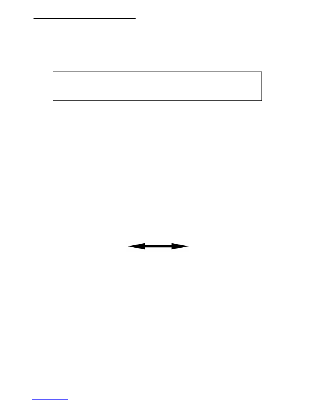
Adjusting and Closing Quick-releases
Open
Closed
Quick-releases are used in a number of places on your trike; it is important that they are tightened correctly. A
quick-release that isn’t fully and properly closed can result in parts coming loose or moving while riding. This
could cause a serious accident.
A quick-release system consists of two basic parts: a lever that provides the clamping force and an adjusting nut
that alters the clamping tension.
With the part you are clamping located properly, adjust the quick-release by opening it, holding both ends and
turning one clockwise until, when you close the lever, you feel some resistance. At this poi nt, try to close the
lever fully. The adjustment is correct when you can fully close the lever, but with some effort (the lever should
leave its impression in the palm of your hand). If you can only close the lever part way, open it, unscrew the
adjusting nut slightly and try again. If it closes too easily, tighten it up a tiny bit and try again. Do not try to
tighten the quick-release by winding the lever around; it will not tighten enough to be safe.
Right…… let’s begin assembly!
Page 6

6
2.1 Unpacking
Carefully unpack the contents of the box and inspect for any damage that may have occurred during shipping.
You should be able to unpack your trike without resorting to a knife; if you use one, be careful not to cut through
the parts or to mark the paintwork. Have a good look at the various packages and familiarize yourself with the
various parts. In addition to the main components shown below, there are other small packages of parts. Don’t
open them just yet; leave them sealed until you need them.
Main frame (cruciform)
Front Boom
Rear Suspension
(seen folded here)
Chainset
Page 7

7
Handlebars
Front Wheels (drum
brake version shown)
Rear Wheel
Rear and Front
Derailleurs
Chaintubes
Axle bolts
Page 8

8
Seat Mount
TT Bracket (standard
with T only)
Seat Cover and Frame
(mesh seat models)
Seat and Cover (hard-
shell seat models)
Page 9

9
2.2 Fit and set the handlebars to an approximate position.
All versions: Slacken off the two clamps on the steerer,
insert the handlebars and adjust them to an upright
position. They only need to be lightly tightened at this
stage.
Find the cable outer casings that were packed with the
derailleurs. Slide them over the uncoiled shifter cables.
One of the long ones goes on the left cable, and the
shorter one on the right cable. The second long cable
housing will be used later.
Note: If you have purchased the optional quick-release
kit, please refer to the instructions for their installation in
Accessories Section of this manual.
Drum Brake Version
: Find the bag containing the
handlebars. Also find the bag containing the brake cables
(with the derailleurs). These are the ones with the inner
cables installed. Squeeze the brake lever, and slide the
small barrel end into the hanging bracket on the lever.
Feed the inner cable down through the slot on the front
of the lever (you may have to turn the adjuster to line up
the slots).
Disc Brake Version
: Find the bag containing the
handlebars. Also find the box containing the hydraulic
brakes. You will have to remove the cable brake levers
from the handlebars and install the hydraulic brake
levers. Note how the Grip-shift shifter is positioned on
the handlebars. Pull the rubber handlebar grip from the
end of the handlebar. If the rubber half-grip doesn’t
want to come off, lift the top edge of the rubber grip and
dribble a little water down inside (an old spoke or
something similar can help lift the grip and let the water
go a little deeper). Undo the shifter locking screw (top
picture) and gently pulling the shifter assembly from the
handlebars. Undo the brake lever clamp bolt and remove
the lever. Re-install the shifter and the (dry) rubber halfgrip. Push the rubber half-grip so it is flush with the end
of the handlebar, then slide the shifter up to it and
tighten the locking screw. Now fasten the hydraulic
brake lever onto the handlebar. NOTE: the brake levers
are handed. The correct lever will put the oil reservoir
(with the logo on the cover) facing away from the seat
and the rider. Loosen and remove the bolt of the brake
lever clamp with a 4mm Allen wrench. Place the
lever/clamp assembly onto the handle bars (the lever
clamp is in 2 parts, so it can be installed after the shifter
is in place.) and position brake lever so it is on the
forward side of the handlebar. Be sure to slide the lever
up close to the base of the shifter. Replace and tighten
the bolt to 1.7-2.26 Nm (15-20 In. lbs).
Page 10

10
2.3a Fit front drum brake wheels
Note: if you have purchased disc brakes,
please refer section 2.3b
Note: If you have purchased the optional quick-
release kit, please refer to the instructions for its
installation in Accessories Section of this manual.
Located in a pack are the drum brake pins. These
pins need to be fastened onto the kingposts.
They are provided with hi-tensile bolts that
appear to have paint on their threads. This is
threadlocking adhesive, and it must not be
removed. If you remove and replace the drum
pin bolts, they must be held in place with Loctite
243 Threadlocker or equivalent.
Put the bolt (with the washer under the head)
through the centre, elongated hole in the kingpost
brake mount, thread the drum brake pin on the
other side, and tighten gently. This should be
only just finger-tight, so you are able to slide the
pin in the elongated hole. Do not make this bolt
tight at this time; it will need to be adjusted later.
Identify the left-hand and right-hand wheels (the
labels are on tape labels fastened to the spokes).
There should also be a bag with the drum brake
baking plates and spacers in it. Locate the front
wheel 12mm axle bolts and 12mm nylock nuts.
Slide an axle bolt through the hub from the
outside of the wheel (the side with the five webs
on the hub flange), then fit the small brake plate
spacer over the axle with the small shoulder on
the spacer against the bearing in the hub. Slide
on the brake plate. Now slide the bolt with the
complete wheel assembly through the kingpost,
locating the single hole in the black brake plate
onto the drum brake pin you previously installed.
Tip – make sure
the brake plate is
located on the pin
as this stops the
plate rotating.
This is essential
for proper
operation of the
brake.
With everything located, add the M12 nylock nut and tighten onto the bolt which is protruding on the inside of the
kingpost. A 10mm hex key and a 19mm wrench are needed to tighten the front wheels. Lightly tighten the
axle bolt, then check that the drum pin is properly located. Tighten the drum pin bolt to 10-11 ft-lb (13-14 nm).
Now, finally, tighten the axle bolt (see table in Appendix A for torque setting). When using a hex key and
wrench, this would be as tight as you can comfortably manage. It is important that these bolts are tight; you will
not damage the bearing by tightening to the required torque.
Repeat the fitting procedure for the other wheel.
Page 11

11
2.3b Fit front disc brake wheels
Note: if you have purchased drum brakes, please refer
section 2.3a
Note: If you have purchased the optional quick-release kit,
please refer to the instructions for its installation in
Accessories Section of this manual.
Identify the left-hand and right-hand wheels (there are tape
labels fastened to the spokes).
First, the disc brake rotors must be mounted on the hubs.
Place the disc rotor on the hub mounting surface. Be sure
that the arrow on the disc is pointing in the same direction of
the forward wheel rotation. Using a Torx T25 driver, install
then tighten the bolts to a torque of 6-7 Nm (4.5-5 ft-lbs).
Note: the bolts have what appears to be paint on their
threads. This is threadlocking adhesive, and it must not be
removed. If you remove and replace the rotor bolts, they
must be held in place with Loctite 243 Threadlocker or
equivalent.
Locate the front wheel 12mm axle bolts, axle caps and 12mm nylock nuts. Also locate the aluminium spacer
tubes for the axles, which are supplied in a bag (along with 4 M5 washers) with the disc brakes. Slide the outside
axle cap over the axle, then push the axle bolt through the hub from the outside of the wheel (the side opposite
the rotor). Now slide the bolt with the complete wheel assembly through the kingpost.
With everything located, slide the aluminium spacer tube over the end of the bolt (now protruding on the inside
of the kingpost), and then tighten the M12 nylock nut onto the thread. A 10mm hex key and a 19mm wrench are
needed to tighten the front wheels. The bolt must be done up quite tight (see table in Appendix A for torque
setting). When using a hex key and wrench, this would be as tight as you can comfortably manage. It is
important that these bolts are tight; you will not damage the bearing by tightening to the required torque.
Repeat the fitting procedure for the other wheel.
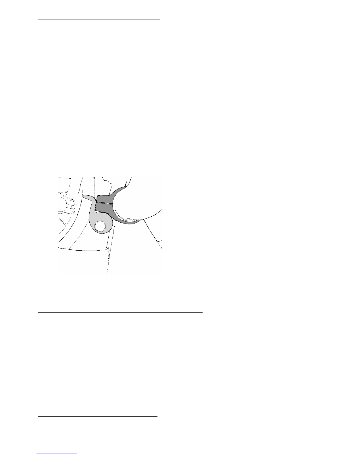
2.4a Connecting the front drum brakes.
Note: if you have purchased disc brakes, please refer section 2.4b
Slide the brake cable adjusting piece
into the lower slot in the brake plate.
Slide the brake cable clamping barrel
onto the brake cable, pull the slack
out of the cable and clamp the barrel
into place.
Adjust the brake by screwing out the
adjuster until the wheel starts to
drag slightly when spun. Screw in
again slightly until the wheel runs
freely. Screw down the locking ring
tightly.
Page 12

12
2.4b Installing and connecting the front disc brakes.
Note: if you have purchased drum brakes, please refer section 2.4a
The disc brake system is supplied fully assembled and bled. It is strongly recommended that you install the
brakes supplied without disconnecting any hoses or attempting to shorten the hose
Route the hose down to the kingpost disc mount. Make sure the hose is running in a position where it will not
twist, kink, or be damaged or pinched. Also check for chaffing of the hose on the tire or the trackrod. The hose
should lead in a fair curve between the lever and the mounted caliper. If it doesn’t, it is possible to twist the
hose in its connector at the lever end until the hose runs smoothly to the caliper
(caliper above shown mounted on bicycle forks)
Mounting the Caliper
New brakes are supplied fully retracted with a red
plastic insert between the pads. With a firm grip, pull
the red insert out from between the pads (it just clips in
place).
Do not squeeze the brake lever until the caliper is
installed. If you do, the brake pistons will be
overextended and you will need a bike shop to
rebuild your caliper.
Slip the caliper over the rotor and then rotate it up to
the kingpost. Align mounting holes with those on the
caliper and fix with the supplied caliper bolts. It is
important to centre the caliper over the disc rotor using
some of the supplied caliper shim washers between the
caliper and disc mount. This is done by trial until the
correct position is achieved. We have also supplied 4
thicker washers (packed with the aluminium axle
spacers) which may be needed. The pads should not
contact the rotor unless the lever is pulled.
Fitting the shims can be a bit
frustrating, as they tend to fall out
when the caliper mounting bolt is
withdrawn. Try applying a thin film of
grease to the shims; they will stick to
each other and to the caliper body,
making it easier to make adjustments.
If you still find it difficult, the wheel
can be removed each time you change
the shims. It’s slower this way, but
much easier to work around the caliper
bolts.
Once the caliper has been centred and wheels spin
freely (without dragging), fully tighten the caliper bolts
with a 5mm Allen wrench to a torque of 11–13 Nm (97
to 114 in. lbs.) Check that the caliper is still mounted
centrally over the rotor.
Now sit down and read the instruction booklet that
came with your brakes.
Warning: If you are not confident of installing your brakes
correctly, we strongly recommended that you have a
competent cycle mechanic install your disc brake system.
Always wear protective clothing, safety glasses and gloves
when servicing this system.
Page 13

13
2.5 Fitting the parking brake strap
There are 2 parking brake straps made of Velcro and they wrap around the brake lever and grip as seen below.
They are essential if you do not want your trike going off on it’s own. You will be surprised how little a slope is
necessary to get the trike moving. Gusts of wind are also capable of moving a trike that doesn’t have a parking
brake. The brake straps can be left dangling on the handlebars when not in use, or removed and stowed in a
handy pocket or bag.
The Parking brake strap can be
stored like this when not in use.
Caution: Don’t rely solely on the parking brake
straps for the security of your trike, especially
when you park on a steep hill. Point the t r ike
towards a wall or curb so it cannot roll far.
Make sure the Velcro® strap is secured – Your
trike will attract attention, and Velcro® is an
irresistible temptation to young children.
Page 14

14
2.6 Fitting the rear section to the cruciform
Slide the rear section into the cruciform, taking care not to damage the
plastic shim located inside the rear of the main frame. A small amount
of lubricant has been applied at the factory. Evenly tighten the two
frame bolts with a 5mm hex key, until the bolts just bite. Align the rear
section by eye so it is vertical (stand back a few feet to get a better
view). Tighten the two bolts by ¼ turn alternately until the rear section
is just clamped enough to prevent it moving around (you will need to
adjust this again later).
If you have opted for a different elastomer from the standard, remove
the red elastomer from the suspension swing-arm. This is done by
pulling and twisting it from its retaining pin, then pushing the new
elastomer onto the pin in its place.
Note: If you have purchased the option Quick-release kit, do not
put any quick-releases into the frame bosses. You must use the
M6 bolts which have already been installed.
Note: If you have purchased the optional rear disc brake kit, please
refer to the instructions for the kit in Accessories Section of this manual.
Unclip the quick-release from the spokes of the rear wheel and thread it through the centre of the axle. The
lever should be on the side opposite the gears. Fit the rear wheel to the rear swingarm. You may find this easier
if the Velcro restraining strap on the swingarm is fastened around the rear section main tube.
If you have a ‘T’, or are fitting the TT bracket for any reason, now is the time to fasten it in place. The first
mounting bolt passes through the single mounting hole and the front mounting position on the tube top. Pass
the 2
nd
mounting bolt through the appropriate hole and the back mounting position. The correct position for the
‘T’ is as shown on the right. For other applications, the correct position will depend on the application.
2.7a Assembling the seat – mesh seat
Find the seat frame and the bag with the seat cover in it.
Unfold the cover and identify which is the top, bottom,
front and back. The top can be identified by the cut-out
just below a single strap. The back can be identified by
the wide cordura bands running down the cover.
Before you begin assembly, locate the O-rings in the
cover pack. Each O-ring needs to be slipped onto a
strap on the cover, and pushed 8" (200mm) or more
down the strap. These O-rings are used to hold down
the loose tails of the straps after the seat has been
assembled.
Page 15

15
Aligning the top of the cover with the top of the seat
frame, place the back of the cover against the frame.
Thread the top strap through the top buckle, and pull
snug. Thread the next strap down through its
corresponding buckle and pull snug. Make sure the seat
cover is centred on the seat frame and the top of the
cover is not to high or low. Work your way down the
seat frame, fastening up the straps snugly as you go.
When you reach the bottom, check the cover for a
smooth, symmetrical fit. When you are happy with the
appearance of the seat, tighten the bottom 5 straps so
they are tight. If you’re got the optional seat foam, push
it between the seat bottom and the 5 bottom straps
before tightening. The rest of the straps can be adjusted
to your preference after you sit on the trike. A good
starting point is to slack off each strap in turn, and
retighten, pulling the strap gently between your thumb
and forefinger. Be careful about over-tightening the
straps on the back of the seat; too loose is more
comfortable than too tight. When all the straps are
adjusted, tuck the loose tails into the O-rings so they
don’t flap about.
Page 16

16
2.7b Assembling the seat – hard-shell seat
The hard-shell seat is supplied with 2 seat mounting
brackets, which have to be fastened to the seat. The
lower bracket is the wider one, and fastens
underneath through the pre-drilled holes. The upper
bracket is narrower, and can be mounted in one of
two positions. The lower position is used for most
riders. The upper position is only for those riders that
want maximum seat recline. In this upper position,
the rear suspension will have to be pulled further out
of the main frame.
The flag mount bracket consists of 2 metal clips and a
short length of stainless steel tubing with one end
partially closed. The flag mount is positioned on the
back of the seat as shown in the photograph, with the
closed end facing down.
The ‘Love Handles’ help keep the rider located on the
hard-shell seat; their installation is optional. To install
the Love Handles, bolt the slots on the Handles
through the pre-drilled holes in the seat with the Love
Handles resting on the inside surface of the seat. The
washers go on the back of the seat. Install the
supplied covers. The Love Handles can be adjusted
for width by loosening the bolts and sliding them to
the required position.
To install the breathable cover, slip the pockets on each end of the cover over the ends of the seat, paying
attention that the Velcro fastenings line up (if they don’t, the cover is on upside down). Press the cover firmly
onto the Velcro.
Page 17
17
2.8 Fit the seat to the lowest position
The seat is provided with 4 plastic SP-6 clamps. Two of these
clamps go around the bottom seat rail, and the other 2 go
around the top rail on the hard-shell seat or the 3
rd
rail
(counting from the bottom) on the mesh seat.
The 2 clips that go around the bottom rail are provided with
quick-release clamps. Place the clips on the bottom rail as
shown in the picture below, and then screw the quick-release
into the clip. Do not forget the small plastic spacer; the quickrelease will not work reliably without it.
The 2 clips that go on the upper rail are provided with M5
fasteners; quick-releases are not necessary as the seat mount
is held to the frame with a quick-release. Clip the SP-6
clamps to the rail and thread the bolts into place.
Set the 3 position upper seat mount in the lowest position (see photo). There is a quick-release skewer that goes
through the front hole on the top of the rear section. Place the seat onto the trike and see if it lines up with the
two mounting cups. Get the seat to fit by sliding the rear section in or out. Try to get the seat mount to sit at an
angle similar to the picture below right. Hold the seat on loosely with the 4 pl astic clips supplied (quick-release
clips on the bottom, and bolted clips on the top) and then tighten the 2 lower quick-releases. Tighten the upper
seat mount quick-release, and then tighten the 2 upper plastic clip bolts. Check to see that the rear section is
still upright and then tighten the two rear section main clamp bolts evenly and tightly.
2.9 Fit the front boom to an approximate position.
Fit the front boom into the frame taking care not
to damage the plastic shim located inside the front
of the main frame. Position the boom at
approximately a hands span from the base of the
front derailleur post to the end of the main
cruciform.
Note: If you have purchased the optional quickrelease kit, please refer to the instructions for its
installation in Accessories Section of this manual.
2.10 Fit the optional chainring guard
If you have purchased the optional Chainring Guard, please refer to the instructions for its installation in
Page 18

18
Accessories Section of this manual before continuing assembly.
2.11 Fit the optional chainrings
If you have purchased either the 55 tooth outer chainring or the 26 tooth inner chainring, refer to the instructions
for their installation in Accessories Section of this manual before continuing assembly.
2.12 Fit the chainset
You now need to install the left and right sides of the chainset. Place the right crank on the right-hand side
square bottom bracket spindle. Put the supplied chainset bolt into the centre hole of the crank and tighten using
the 8mm hex key. This bolt must be very tight! Repeat for the left-hand crank, ensuring that the crank arm is
lined up with the right-hand crank. Again, tighten very tight using the 8mm hex key.
2.13 Fit the pedals
(Your own if not ordered from us) – Note: the pedal threads are handed. The right hand pedal tightens in the
normal direction; the left-hand pedal has a left hand thread, and tightens in the opposite direction to normal.
2.14 Adjust the seat angle
Sit on the trike (see section 5.1) and decide whether the seat angle suits you. The seat can be set more upright
(it was set to maximum recline in section 2.7) by simply opening the seat mount quick-release, sliding the seat
mount off the quick-release, and slotting it back over using a different set of slots. Please refer to section 3.4
2.15 Set the handlebars
The handlebars on your trike adjust forward and back, as well as for width. Sit on the trike and adjust the bars
to a position that feels comfortable. Typically, the angle of your elbow joint should be slightly more than 90
degrees open. Check the clearance between your hands and the wheels; also check the clearance between the
brake levers and frame at full steering lock. Adjusting the handlebars to their widest comfortable position that
doesn't interfere with the front wheels will give you the maximum amount of steering movement. Tighten the
handlebar clamp bolts.
Do not use the handlebars to pull yourself out of the trike with; they are not meant for this
purpose. Under normal use the handlebars will not slip in their clamps, they will however move if
subjected to an abnormal force.
There is also no need to pull on the handlebars when riding. The trike is easily steered wi th a light
grip of the fingers.
2.16 Set the front boom
Set the leg length by sitting on the trike and placing your heel on the pedal. Adjust the boom so that your leg is
almost straight when the pedal is at its furthest away from you. Set the front boom upright (by eye), and then
tighten the 2 clamp bolts.
Check the boom is not extended past its minimum insertion length. The end of the boom should not be visible in
the slot in the underside of the frame.
Page 19

19
2.17 Install and connect the front derailleur
Next, the front derailleur needs to be installed. Its position is determined by the size of outer chainring. Tighten
the supplied M5 bolt lightly so you can adjust the position of the derailleur. The position of the derailleur must be
set so the clearance between the outer plate of the cage and outer chainring is roughly 1 -3mm, when viewed
from the side. When viewed from above, the derailleur cage should be parallel to the outer chainring (not the
middle or inner chainrings). Tighten up the clamp bolt when the derailleur is located correctly.
Thread the front gear cable (left hand shifter) outer casing through the guide on the side of the frame and up
towards the end of the front boom. The front shifter casing is packaged with the handlebars, and it is the longer
one. Thread the inner wire through the outer casing and then through the cable guide tube (chromed noodle).
Pass the cable guide up through the hole on the underside of the front boom, so that it just pokes out of the hole
on the top face of the boom, checking that it is seated correctly.
Pull through any slack cable. While holding the cable taut, turn the shifter through its range of movement to
check the cable moves smoothly and that the cable is properly seated inside the shifter. Clamp the inner wire at
the front derailleur (5-7 Nm, 4-5 ft-lbs).
TIP – make sure the left hand shifter is set to the “L” position in the
indicator window (smallest gear setting) and the cable and outer casing
are located properly in the cable stops.
TIP - Do not trim any cables until you are happy with the various settings of
front boom and gears. The loose end of the cable can be tightly coiled so
that it is out of the way.
2.18 Install and connect the rear derailleur
Fit the rear shifter cable housing over the rear shifter cable (right hand shifter). This is the shorter cable housing
that was packed with the handlebars. Thread the cable housing through the cable guide and into the stop, both
located on the right side of the frame.
Find the bag with the rear derailleur parts in it. Fit the rear derailleur to the rear dropout using a 5mm hex key,
making sure the B-tension adjustment screw doesn’t come into contact with the dropout tab.
Page 20

20
Adjust the B-tension screw so it is screwed in about 2/3 of the way. Check that the rear derailleur stop screws
are approximately set as shown in section 2.22 (final adjustment will take place once the chain is installed)
Fit the long length of gear outer casing into the rear derailleur and around to the cable stop on the rear righthand side of the main frame. Clip the cable outer casing to the 3 guides using the black plastic clips provided.
Thread the inner wire cable through the outer casing. Screw the barrel adjuster at the shifter fully in first, then
out 1 turn. Do the same with the adjuster at the rear derailleur. Check the cable is located correctly in the cable
guide. Holding the cable taut, turn the shifter through its range of movement to check the cable moves smoothly
and that the cable is properly seated inside the shifter, then connect and clamp the cable at the rear derailleur
while gently pulling through any slack in the system.
TIP – make sure the right hand shifter is set to the “9” position in the
indicator window (smallest sprocket setting) and the cable and outer casing
are located properly.
Cut the cable off leaving about 3” (75mm) past the cable clamp, and crimp the cable end cover onto the cable
end.
Check at this point that the brake and shifter cables are routed correctly. They should look like the photos below.
2.19 Assemble the chain tubes
Lay out the parts of the chaintube as shown in the photo. The chaintubes are bolted onto the pulley plate with
plastic clips. It is important that the chaintubes are assembled as shown, particularly the chain tube with the
metal clip. This clip keeps that tube from sliding forward into the pulley. Push the self-locking bolt through
Page 21

21
the bearing in the pulley, locating the space washers as shown in the diagram. Push the bolt through the middle
of the pulley plate, and mount the chain tube assembly and pulley onto the frame. Ensure that the small tab on
the frame locates in the notch on the pulley plate (just above the bolt). When tightening the plastic clips onto
the pulley plate, be careful about not over-tightening the bolts; it is possible to damage the pl astic clips if you do.
Note: The main bolt which holds the pulley and
pulley plate to the trike is a self-locking bolt. It has
a small piece of nylon imbedded in the threads. You
will feel some resistance when the nylon starts to move
down the threaded lug in the frame, but keep turning the
bolt until it is tight.
Page 22

22
2.20 Check the chain tube lengths
Check for clearance between the chain tubes and the front chainset. If the top chain tube at the front is too long,
shorten by cutting the tube at the front end to the required length with a sharp knife.
If the lower front tube is too long, adjust the front position of the tube by loosening the tube clamp at the pulley
and sliding the lower tube rearward to the required position at the front and re-clamp the tube.
When the front of the lower tube is properly positioned, trim the rear of the lower tube off so it is the same level
with the end of the upper rear chain tube. This is essential to allow proper folding of the rear section.
2.21 Fit the chain
Find the pack containing the chains and the ‘R’ pins. Remove the pulley and chain tube assembly from the trike.
Clip an ‘R’ pin through one end of each of the two chains. Hold the chain tube assembly vertically and drop a
chain down each tube (for the top tube, pass the chain around the pulley and down the other tube); the ‘R’ pins
will prevent the chains from dropping right through.
Add two more ‘R’ pins to the bottom ends of the chains; this keeps them in the chain tubes while they are being
fitted. Refit the chain tube set and pulley to the trike making sure the tab on the frame is engaged in the pulley
plate. Also make sure the pulley clamping bolt is tight. Check the pulley plate is secure and cannot rotate.
Page 23

23
Twist the right hand rear shifter to the “9” position so that the rear derailleur lines up with the smallest rear
sprocket. Twist the left hand front shifter to the “1” position so that the front derailleur lines up with the smallest
front chainring.
At the front of the trike, pull the top chain through the top chain tube. Pass the chain through the front derailleur
cage, around the small chain ring and then connect it to the lower return chain at the front using the quick
connect link. Remove the ‘R’ pin from the top and bottom chains.
Now, checking that the chain is not twisted inside the chain tube, thread the bottom chain up through the
derailleur and over the cassette.
TIP - make sure the chain is correctly routed through the rear derailleur cage
and goes the correct side of the tab on the derailleur cage between the two
jockey wheels.
Connect the bottom chain to the top chain using the quick connect links supplied. Make sure that the chain is not
twisted. Remove the last 2 ‘R’ pins.
Now set the chain to length by adding or removing a section of chain between the rear derailleur and
the lower chain tube with a chain rivet tool as below. Move the chain until one of the connecting links
can be seen between the rear derailleur and the lower chain tube. Open the link and then work out
how much chain to remove. Use an R pin to help stop the chain going back up the chain tube.
Make sure you leave enough chain so that it can run from largest chain ring to largest cassette
sprocket.
Page 24

24
Add 2 links (with the chain on both the largest sprocket and the largest chainring). This should leave just enough
slack so that the rear derailleur jockey wheels are pointing forward but so that they can still move up a fraction.
Then check that there is not too much slack when using the smallest chain ring and smallest cassette sprocket.
TIP – get an extra pair of hands to help with this. Make
sure that any links you alter with the chain link
remover are not stiff on the rivets. If in doubt, remove
fewer links than you think as removing links is easier
than riveting links back in. Use the quick disconnect
link to open the chain and then punch out links and
quick connect back together.
When you've finished adjusting the chain length, check
at the pulley plate where the chain enters and leaves
the chain tubes. The plastic clips should be adjusted
vertically so the chain is running centrally where it
enters and exits the chaintubes. This is also the
position where the chain runs at it quietest.
The chain tubes have come with a small piece of nylon
webbing with 2 square holes in it. This holds the back
end of the lower chaintube, and keeps it from sagging.
The webbing strap is slipped over the rear cable stop on
the frame. Pull the cable housing from the stop, and
then slip the hole in one end of the strap over the cable
stop. Loop the strap around the bottom chain tube and
then slip the other loop over the cable stop. Replace
the cable housing in the cable stop.
2.22 Check the gear shifting
Check the rear gears are shifting correctly. Raise the rear wheel off the ground by getting a helper to hold it up
or standing an object under the left side dropout so that the pedals can be turned making the chain turn the rear
wheel. Gently twist the right hand shifter up through the gears one click at a time whilst turning the pedals.
Take care on the rear cassette that the chain does not jump between the largest sprocket and the spokes. This is
prevented by the low adjustment limit screw on the rear derailleur which can be adjusted if required. Check also
that the chain doesn't drop off between the smallest sprocket and the dropout. This is adjusted using the High
Adjustment screw.
Page 25

25
Set the left front shifter to the “1” position and the right rear shifter to the “9” whilst turning the pedals then
check that there is no excessive slack in the gear cables. Slack must be removed by unclamping, pulling through
and re-clamping the gear cables. Check the rear derailleur indexing by turning the right hand (rear) shifter 1
click to the “8” position whilst turning the pedals and checking that the rear derailleur has shifted the chain to the
second from smallest sprocket. Adjust shifting by carefully turning the cable adjuster at the back of the trike on
the rear derailleur until the chain runs smoothly on the second from smallest sprocket. Shift back to "9" and try
shifting up to "8" again. It is not enough that the chain should run quietly in each gear, it should also move
smartly from one sprocket to the next, without clattering or jamming. Now check for smooth changing up
through the range, checking one pair of sprockets at a time (8-7, 7-6, etc.) Make any minor adjustments by
turning the cable adjuster.
Cable Adjustment
Low adjustment
Turn the low adjustment screw
so that the guide pulley moves
to a position directly in line with
the largest sprocket
High adjustment
Turn the high adjustment screw
to adjust the derailleur so that
the guide pulley is in line with
the outer line of the smallest
sprocket when looking fro the
rear
Adjusting the B-tension
adjustment screw
With the chain on the largest
sprocket and the smallest
chainring, turn the cranks
backwards. Adjust the screw so
the guide pulley as close as
possible to the sprocket without
touching. Move the chain to the
smallest sprocket to check that
the guide pulley doesn’t touch.
Check the front gears are shifting correctly. Adjust the cage limit screws if required.
Page 26

26
2.23 Fit the rear mudguard
Note: If you have purchased the optional quick-release, full-wrap rear mudguard kit, please refer to the
instructions for its installation in Accessories Section of this manual.
The standard rear mudguard clips quickly on and off of a bracket which is part of the seat mount. Assemble the
parts of the mudguard as shown in the picture below, and clip into place on the upper seat mount. Tighten the
thumbscrew to secure the mudguard.
Page 27

27
2.24 Fit the mirror
The mirror comes with instructions
showing how it is to be assembled. The
mirror is mounted in the top of one of
the handlebars (right handlebar if you
drive on the left, left handlebar if you
drive on the right). A plastic plug is
provided for the opposite handlebar.
Many people prefer to ride with a mirror
both sides.
If you have fitted the option bar-end
shifters, you will have fastened a mirror
mount to the handlebars. Insert the
mirror into the end of the mirror mount
and tighten.
2.25 Fit the flag
Place the flag in the flag holder hole in
the left or right side at the top of the
seat frame.
If you have an 'S', the flag mounts in
the tube on the top seat mount rail.
2.26 Reflectors and bell
Reflectors and a bell are supplied with your trike. The bell can be mounted anywhere on the handlebars where it
can be reached easily and doesn't interfere with steering the trike. The reflectors have brackets which allow the
front reflector to be mounted on the front derailleur post, and the rear reflector to be mounted on the top rail of
the seat.
2.27 Check nuts and bolts
Generally, check all nuts, bolts and quick-releases to make sure everything is tight.
Page 28

28
3.0 Adjusting your TRICE
Fine-tuning for leg length, seat angle, handle bar width / angle, brake lever reach, tyre pressure etc are all well
worth taking time to set to your personal preference.
TIP - Experiment but always go for a reasonable (a mile or two) test ride
to decide if an adjustment is right for you.
3.1 Tyre pressure
Typical tyre pressure for the standard tyres is about 70psi (4.6 bar). Do not inflate the tyres more than the
maximum pressure recommended on the tyre sidewalls. You will need to experiment a bit to find the tyre
pressure that suits you best. Higher pressures will allow the trike roll more easily, but will transmit more road
shock to the rider. Lower pressures will feel much more comfortable, but there can be more rolling resistance.
Also try experimenting with tyres; there are now large cruiser tyres available which can provide a comfortable
ride and reasonably low rolling resistance, as well as small high-pressure racing tyres that offer very-low rolling
resistance and sport-car type handling
3.2a Mesh seat cover
When new both the seat cover and the straps stretch a little, and in the first few weeks of use you may need to
re-tension the seat by tightening up the straps. In time it will settle down. For maximum comfort you may need
to tighten the cover more in some places than in others. In general, the base of the seat should be tight, and the
back looser.
3.2b Fitting the hard-shell seat to you
The hard-shell seat is supplied with adhesive-backed foam. Try experimenting with cutting out pads and sticking
them on. You should be trying to pad any spaces where you do not touch the seat. Don't pad the pressure
points; pad around them. You can temporarily hold the pads in place with a bit of adhesive tape. Don't peel off
backing of the foam sheet until you are certain of their position. The adhesive is very
strong.
3.3 Suspension adjustment
The suspension adjusted is accomplished by the selection
of elastomers and mounting positions. To adjust the
suspension, find an assistant, and then proceed as follows:
• Shift the chain onto the smallest sprocket at the rear
('9')
• Select the elastomer based on the table in Appendix B.
• Screw the shock pin into the centre hole in the shock
plate.
• Sit on the trike and put your feet on the pedals. Press
lightly to apply a small amount of tension to the upper
chain.
• Have your assistant look at the trike from the side. In
profile, the chain should appear to pass about through
the middle of the suspension pivot. If you don't have
an assistant, reach under the seat and put your finger
(carefully! Don't trap it in the pivot) into the hollow
pivot pin. Feel whether the chain is higher or lower
than the centre of the pivot. If the chain is higher than
the pivot, the suspension is too compressed, and the
elastomer has to be moved to the upper hole on the
shock plate. If the chain is still higher than the pivot,
try replacing the elastomer with a harder one.
• If the chain is lower than the pivot, the suspension is
not compressed enough, and the elastomer needs to
be moved to the lower mounting hole. If the chain is
still lower than the pivot, try replacing the elastomer
with a softer one.
The elastomer is removed by pulling and twisting it off of
the shock pin. Unscrew the pin and move it to the new
hole. Press the elastomer into place on the pin again.
Page 29

29
The elastomers have different compression characteristics, and you may find other combinations of elastomer
hardness and pin position which suit the roads you ride on and your riding style better; it is just a matter of
trying different combinations. The elastomer system is simple and small enough that you can carry a couple of
elastomers in your pocket and change them when you are out on a ride.
If you carry a significant amount of luggage (perhaps you are going on a long tour), re-tune the suspension with
the trike loaded; you will definitely notice the difference. It is possible to fit 2 lighter elastomers side-by-side if
you find one elastomer doesn’t provide the ride characteristics you want.
Elastomers will become stiffer in cold weather, and may take a couple of miles before warming up from use. In
very cold weather, it would be possible to remove the elastomer and keep it warm (in your pocket) while you are
away from the trike. Riding with a cold, stiff elastomer will not harm the trike or the elastomer; you just won’t
feel all the benefits of riding with suspension.
The rear swingarm is held in the normal position by a double-sided Velcro strap. This bolts on through the
mudguard hole as shown in the picture above. The purpose of the strap is to keep the rear swingarm from
dangling when the trike is picked up. To fasten, place the trike on the ground with no weight on it. Wrap one
side of the Velcro strap around the curved frame tube where the corresponding Velcro strip has been placed. The
other loose end of the Velcro strap is then wrapped over the first.
3.4 Seat angle adjustment
The seat has 3 positions of adjustment, and adjustment is simple and quick.
• Loosen the seat mount quick-release lever.
• If you want to make the seat more reclined set it to the slots closest to the seat cup. If you want to
make the seat less reclined, then set it to the slots furthest from the seat cup.
• Re-tighten the seat mount quick-release. If you have fitted the suspension rack, make sure the rack
mounting plates are also hooked in place.
3.5 Seat brackets
There are 3 accessory seat mounting brackets available for your trike. The FF and FB brackets are used to move
the position of the seat forward or back. The FF and FB brackets are installed onto the trike in place of the seat,
using the 2 stainless steel Mikalor clamps provided. A strip of adhesive-backed protection strip is supplied to be
fitted to the main seat mount on the trike where the small tube bears against it. A cable tie is also provided to
strap the small tube to the main frame.
The FF bracket is used to move the seat forward on the
trike. This is useful if the rider is small, and cannot
adjust the pedals close enough without their heels hitting
the crossaxle. Fit the FF bracket to the trike with the
supplied clamps, then fit the seat as you would normally
(section 2.7). You will have to push the rear section into
the frame a little.
Page 30

30
The FB bracket is used to move the seat backwards on
the trike. This is useful if the rider is has long legs, and
cannot adjust the pedals far enough away from them. Fit
the FB bracket to the trike with the supplied clamps, then
fit the seat as you would normally (section 2.7). The
plastic clamps will have to be turned around from how
they are normally mounted. You will have to pull the rear
section out of the frame a little.
Note: using this bracket with the hard-shell seat will
reduce the maximum seat recline available.
The TT bracket is used as standard on the ‘T’ and is also
used by shorter riders on the Q who would like to sit
more upright. The TT bracket has 4 positions and can be
mounted forwards or backwards, giving a number of
positions for the upper seat mount.
Off Road
Use the TT bracket on the 2007 Trice Q/QNT
in conjunction with the FB bracket to
improve rear wheel traction and weight
distribution for off-road riding (not a
recommended combination for short riders also not compatible with pre 2007 Q, S or T)
Page 31

31
3.6 Leg length
A small adjustment can be quite noticeable, just like adjusting the saddle on a conventional bike.
• Change gear to the smallest chain ring.
• Undo the two clamp bolts under the front boom. They must be loose.
• Slide the front boom in or out by twisting and pulling or pushing
TIP – It is easier to move the boom if you get a helper to sit on the
trike with both front brakes on.
• Check the boom is vertical by eye. It's not necessary to measure anything, if it looks upright, then it
will be fine.
• Tighten the two clamp bolts under the front boom.
• If you have moved the boom by more than approximately 10mm you will need to check that you
have the correct chain length (see Fitting the Chain - section 2).
3.7 Brake lever adjustment
The position of the brake lever relative to the
handlebars (the ‘reach’) can be adjusted. It can be
useful for move the lever closer to the handlebar for
riders with smaller hands.
For Gator Hydraulic brakes, there is an adjustment
screw on the inside of the lever near the pivot. Adjust
the position of the lever using the adjuster screw to the
desired lever reach. Use a 2 mm hex key to adjust the
screw.
For drum brakes, the lever has a reach adjustment
screw on the underside of the lever body, between the
cable entry and the handlebar clamp. Use a 2 mm hex
key to adjust the screw.
Other knob, located on the inside of the lever, controls
the leverage ratio of the brake lever. Changing this
setting changes the amount of cable the lever pulls,
and affects the feel of the brakes. The usual position is
with the knob turned fully clockwise, so that the
minimum amount of cable is pulled (but with the
maximum power). If you fit other brakes, you will
need to experiment to find the best position.
Page 32

32
4.0 ICE Optional Accessories
4.1 Front mudguards
Assembly
The mudguards consist of three parts
• the mudguard bracket, which fastens to the trike
• the mudguard frame, which fastens to the bracket, and holds the plastic profile in place. These are left
and right handed.
• the plastic profile. This is pre-drilled to fit the frame
Begin by bolting the profile to the frame. The 3 drillings in the profile ensure that it can only be mounted one way.
A M5 x 12mm button-head bolt goes through the hole in the frame, a rubber washer is then placed on the bolt,
followed by the profile, the metal washer, and then the nylock nut. Tighten the nut snugly until the rubber washer
begins to compress. Do not over-tighten.
The bracket is then bolted to the frame. Using the M5x16 cap-head bolts with a metal washer on them, pass them
through the bracket and the frame as shown in the photo, and then fasten on the other metal washer and nut.
Tighten snugly (you will be adjusting this when you fit the mudguards to the trike)
Fitting
Front mudguards fit onto the steering pivots and can be quickly removed by one bolt in each unit.
To fit the mudguards, remove the bolt and washer from the top of the steering pivots and then clamp the
mudguards directly onto the top of the steering pivot re-using the bolt and washer.
TIP – The mudguard clamping bolts do need to be done up tight to prevent the
mudguards from pivoting round in use.
• To remove a mudguard, loosen and remove the single clamping bolt and washer at the top of the steering
pivot on each wheel.
• Cover the exposed mounting hole by re-fitting the bolt and washer.
Page 33

33
Note: If you have purchased the optional quick-release kit, please refer to the instructions for the kit in this
section of this manual.
The mudguards can also be adjusted to fit
various tyre sections. With the mudguard
fitted to the trike, slightly loosen the two bolts
holding the mudguard bracket to the frame
(so the two parts can just be slide against one
another). Move the mudguard frame to
where, if viewed from the side, there is an
even amount of clearance (about 6-8mm)
between the tyre and the mudguard profile.
Always check that the wheel spins freely after
adjusting mudguards.
4.2 Computer
A cycle computer can be fitted with the aid of the optional mounting kit. The computer display mount bolts
(supplied) onto the bottle bosses on the main frame (just in front of the main cross joint).
The sensor mount is fitted to the kingpost balljoint mount and set so that the sensor lines up with the magnet
clamped onto the spokes. The exact position will depend on the model of computer that is installed. To fit the
sensor mount, you will need a thin 11 mm spanner, and a 13mm spanner. The 11 mm spanner is to grip the
small flats of the ball joint under the rubber shield, while you use the 13mm spanner to loosen or tighten the ball
joint nut.
If you are fitting a wireless computer, the display should now be able to receive signals from the sender.
Because wireless computers are designed with upright bicycles in mind, they do not always work well on
recumbent trikes. If you find the computer is under-reading, or not receiving a signal at all, try moving the
position of the sensor so it is higher or lower; the sensor can be mounted below the sensor mount and the sensor
mount can be turned over to gain/lose addition height. As a last resort, the sensor mount can be bent to a more
vertical position, which some wireless computers seem to prefer.
If you are fitting a wired computer, you will first need to secure the display to the display mount. Lead the cable
out from the display (leaving a small amount of slack so the cable is not strained) and along the underside of the
crossaxle to the kingpost. Hold the cable in place temporarily with small pieces of electrical tape. Lead the cable
along the kingpost steerer arm (again, leaving a small amount of slack so the kingpost is free to move without
straining the cable) and secure the sensor to the sensor mount. Any extra cable can be coiled into a small loop
and secured to the steerer arm with a supplied cable tie. Check that the steering is able to move completely and
freely in both directions without straining the cable. Secure the cable to the frame along the underside of the
crossaxle using the supplied cable ties. Some people prefer to secure the cable with a single length of electrical
tape and cable ties securing each end of the tape and cable.
Page 34

34
4.3 “Handlebar” bag side mount
This optional item allows a standard “handlebar” bag to be
mounted beside the seat. The mount is clamped around
the seat frame cross rail and adjusted to the desired
position. The bag side mount is made to take a standard
Klickfix handlebar bag fitting, but many others will fit as
well. Follow the fitting instructions that came with your
bag, to mount the bag onto the side mount.
4.4 Lights.
Front lights may be fitted to the front derailleur tube utilising the
optional ICE front light mount. Rear lights can be mounted to the rear
of the carrier, on the upper seat cross-rail, or on optional neck rest.
The instructions for installing the front light mount are printed on the
packaging. Please ensure that the mount is tightened properly.
4.5 Extra water bottle mount
An extra water bottle mount can be fitted to the seat frame by using the option ICE bottle cage mount and a
bottle cage. Fitting instructions are included with the mounts.
Page 35

35
4.6 Neck rest
Assembly
The neckrest cover needs to be installed on the neckrest frame. Put your
fingers up inside the cover, and peel apart the Velcro® strip near the top.
Now slide the cover over the frame as shown until the top of the frame is
past the Velcro® and is located snugly inside the top of the cover. It is
meant to be a tight fit.
The neck rest is assembled as shown in the diagrams. The cup and socket
washers allow the neck rest to be adjusted forward and back, and sliding the
head rest assembly in the clamping bars allows adjustment for height. An
additional adjustment for angle can be made by reversing the fittings on the
base. There are 2 notches in the base that can engage the rivet on the top
seat rail. The notches are different depths, and by changing which way the
base is clamped on, can change the angle of the whole assembly.
If you have a hard-shell seat, the headrest is fastened to the seat using 2
small clamps and a triangular backing plate. Assemble the headrest as
shown in the diagram below; the location of the aluminium and black plastic
spacers can be altered to adjust the closeness of the headrest from the seat.
Mesh Seat Models
Hard-shell Seat Models
Page 36

36
Headrest Light mount
Adjustment
The optional neck rest is fitted to the top rail of the seat frame. The neck
rest is adjustable for height and angle, and is designed to suit a wide
range of riders. We have found the best position for the neck rest is one
where the pad sits just under the base of the skull. This allows the rider
to wear a helmet, and minimises any transmission of road vibration to
the rider’s head. To adjust the neck rest, slacken off the 2 adjuster nuts
and move the neck rest to the desired position. Most people find the best
position is where it doesn’t touch your neck or head when you are riding
on level ground, but allows you to rest your head when you are climbing.
Making sure that it is upright when viewed from the rear, tighten the two
nuts.
The neck rest light mount is easily installed. Slip the neck rest frame
from the bracket, slide the mount over one leg, and reinstall the frame
onto the bracket. Slide the mount to a suitable height, and tighten the
grub screw to lock in place.
4.7 Quick-release kit
The quick-release kit comes with a set of quick-releases to make folding and disassembling your trike into a quick
and easy job. The kit consists of:
2 x 12mm quick-release axles.
These are installed in place of the 12mm axle bolts.
Remove the finger nut from the end of the quick-release
bolt. Slide the quick-release bolt into the hub from the
outside, in exactly the same manner as you would the
regular 12mm axle. When the bolt has been slid into the
kingpost, screw the finger nut back onto the end of the bolt,
and tighten the quick-release lever.
NOTE: If you fit the decorative hub cap with the
quick-release, please make sure it is fitted the right
way around, so the quick-release base sits inside
the
cap. If fitted the other way around, the cap will
collapse causing the quick-release lever to bend and
snap off.
2 x 6mm front boom quick-releases
These are installed in place of the 2 - 6mm bolts
that clamp the boom into place. Remove the 6mm
bolts from the frame using a 5mm hex key. Slide
the quick-release into the hole where the bolt was,
and thread the quick-release into the frame to
adjust its tightness. Make sure that the aluminium
spacer on the quick-release sits down in the hole
where the head of the bolt used to be. These
quick-releases should not be installed in the
back of the main frame.
2 x 6mm mudguard quick-releases
These replace the 2 bolts that hold the mudguards
in place. Remove the old countersunk bolts using
a 4mm hex key. Slide the quick-releases into the
mudguard brackets and then thread them into the
captive nuts in the kingposts. Screw them down to
adjust the quick-release tension. You do not need
to use the aluminium cap that normally covers the
top of the kingpost. These quick-releases
should not be installed in the back of the main
frame.
Page 37

37
2 x quick-release handlebar clamps
These replace the handlebar clamps which are
installed on your trike. To remove the old clamps,
loosen the clamp bolts with a 5mm hex key, and
then pull them from the end of the centre
handlebar. The quick-release handlebar clamps
are pushed into place, with the quick-release lever
located behind
the handlebar, with the slot in the
clamp roughly lined up with the slot in the centre
handlebar.
4.8 Assembling and fitting the suspension rack
Assemble the rack by finding the upper rack arms, and bolting
them onto the correct lug, as show in the diagram.
The supplied mudguard can now be fastened in place. A M5 x
12mm button-head bolt goes through each mounting hole in the
rack, a rubber washer is then placed on the bolt, followed by the
profile, the metal washer, and then the nylock nut. Tighten the
nut snugly until the rubber washer begins
to compress. Do not
over-tighten.
Fasten any lights or reflectors onto the rear of the rack.
Slide the long quick-release through the lower rack mount (the
spindle welded into the frame)
Slacken off the seat mount quick-release.
To fasten the rack to the trike, it is easiest to undo the top seat
mount quick-release, unclip the top seat mount, and rotate the
seat forward.
Slide the lower mounting dropouts on the rack onto the lower
rack mount on the frame. Rotate the rack forward slightly until
the upper rack arms can slip over the seat mount quick-release.
Rotate the seat back into position, locating the seat mount back
onto the seat mount quick-release. Tighten both quick-releases.
4.9 Rear disc brake
• Fit the rotor – With the wheel out of the bike,
unscrew the quick-release, and then remove the
rubber cap on the non-drive side of the axle.
Underneath you will find the splined end which
will take the rotor. The rotor is slipped over the
splines so the disc is outboard. Put a small
amount of grease on the threads of the locking
ring and screw it down in the centre of the disc.
To tighten the locking ring, insert a Shimano
lock-ring tool (TL-LR15, this is the same tool
that is used to tighten on a rear cassette,
available from any bike shop), and firmly tighten
(40nm, 29ft-lbs). Replace the wheel in the bike.
Page 38

38
• Bolt the brake caliper on – the brake is held on
using the 2 M6 adapter fixing bolts supplied.
Before installing the caliper, slacken the 2 caliper
fixing bolts on the top of the caliper mount, so
the caliper can slide easily over the brake rotor.
• The brake lever is attached to the left-hand
handlebar using the single bolt supplied. Gently
bend the bracket open to slip it over the bar,
then bend back and replace the bolt. Slide the
inner cable through the outer cable housing and
run the outer cable housing to the rear brake,
clipping it in place with cable ties along the left
side of the frame when you are happy with its
position. Check that the lever or cable does not
foul the seat or the track rod anywhere within
the full range of steering movement. Run the
cable housing under the rear swingarm, and
fasten it in place using the cable clips provided
(same type of clip that hold the rear derailleur
cable in place).
• Feed the cable and housing into the socket on
the brake caliper, and attach the end of the
inner cable to the brake caliper arm, making
sure that the lever is in the full ‘off’ (anticlockwise) position. Cut the inner cable, leaving
about 2 inches (50mm) past the clamp, and
crimp the cable end cover onto the inner wire.
• Adjustment – the disc brake has 2 pads inside. Their position is adjusted using a 3mm hex key in the socket
on each side of the caliper. With the caliper on the trike, caliper fixing bolts loosened, and the wheel in place,
wind both pads in until the disc rotor is clamped between them and centered in the caliper. Turn the brake
lever clockwise to ensure the rotor is solidly clamped, and then tighten up the 2 caliper fixing bolts. Turn the
brake lever fully counter-clockwise then back off the pad adjustment just enough for the wheel to run freely
without the pads dragging on the rotor. Test to make sure that when the brake lever is used, the brake grips
properly.
Page 39

39
4.10 Fitting Radical bags
Radical bags are extraordinarily simple to fit. The bags are
simply held the right way up (so you can read the writing in
the side), and they are draped over the seat. The top strap is
either wrapped around the top seat tube if you don't have a
neck rest fitted (photo left), or looped over the neck rest base
if it is fitted (photo lower right). Gently pull the bags until
they fit neatly around the seat.
4.11 Fitting the optional chainrings
If the chainset has already been installed, you will
need to obtain a crank extractor in order to remove
it. These are inexpensive and can be found at any
bike shop.
Page 40

40
• 26 tooth inner chainring - With the chainset removed, use a 5mm hex key to remove the 5 bolts that hold the
inner chainring in place. Note if there is a recessed hole (for the bolt or nut head) in the chainring where the
bolts are fitted; the new ring will have to be re-fitted in the same way. Remove the ring, and replace it with
the 26 tooth ring, and then replace the bolts. Tighten them evenly in a pattern, working on one bolt, then
one opposite. Replace the chainset on the trike.
• 55 tooth outer chainring. To gain proper access to the chainring bolts, it will be necessary to remover the
inner chainring first, following the instructions above. Remove the 5 bolts that hold the middle and outer
chainrings onto the crank arm. You will need to hold onto the nut (the part against the middle chainring)
using either a large flat screwdriver, or special chainring tool (available inexpensively from most good bike
shops or ICE). Note how the bolts fit onto the rings. Swap the large chainring for the optional 55 tooth one,
and reassemble. Be certain to tighten the bolts up evenly before riding the trike.
If you have changed either chainring, you need check the chain lengths again (as shown in section 2) to ensure
that the trike has the correct length of chain.
4.12 Chainring guard
The chainring guard is fitted onto the bottom
bracket shell. If the chainset has been installed,
you will need to obtain a crank extractor in order to
remove it. With the chainset removed, slacken
the single bolt on the chainring guard, and slip the
guard onto the bottom bracket shell, ensuring that
the guard does not touch the front derailleur.
Replace the chainset and tighten. To adjust the position of
the guard, slacken the bolt and rotate the guard until the
top edge is close to, but not touching, the front derailleur.
While turning the pedals, check that there is clearance for
the chain when it is running on, and shifting between, all
three rings.
Page 41

41
4.13 Bar end shifters
Installation instructions are included with the bar end shifter
kits. After you have removed the old twist shifters, remove
the brake lever from the side where you would normally have
a mirror, and then slip the mirror mount over the handlebar
before replacing the brake lever.
Ensure that the mirror mount, brake levers and bar end
shifters are securely tightened before riding the trike.
4.14 Rear full mudguard
To assemble the optional rear full mudguard:
• Lay out the pieces as shown. It is particularly
important that the plastic profile is the
installed the correct way around. Notice the
long and short overhangs from the outer
mounting holes.
• Fasten the 3 arms to the profile as shown. A
M5 x 12mm button-head bolt goes through
the hole in the arm, a rubber washer is then
placed on the bolt, followed by the profile, the
metal washer, and then the nylock nut.
Tighten the nut snugly until the rubber washer
begins to compress. Do not over-tighten.
• Fasten the arms onto the main mount. Note
how the tab on the centre arm engages in the
slot. Do not tighten the adjusting bolts at this
time.
If your Full Wrap Rear Mudguard falls off the trike when going over bumpy roads, check
that the quick-release is done up properly. If it is tight, then the mudguard needs to be
adjusted to give more clearance to the tyre. What is happening is that on large bumps,
the mudguard is bouncing down, touching the tyre, and catching on the tread. This pulls
the mudguard off.
Page 42

42
To fit the optional rear full mudguard:
• Put the supplied M6 bolt through the rear-most disk brake
mounting hole, and tighten the nut on from behind. This
step is not necessary if you have a disc brake already
installed.
• Screw the supplied quick-release and its spacer into the
threaded hole at the rear of the dropout.
• Slip the front slot of the mudguard over
the head of the M6 bolt, and then rotate
the bracket so the rear slot slides down
over the quick-release.
• Tighten the quick-release.
• Slide the adjusting bolts until the
mudguard has even clearance around
the circumference of the tyre.
• NOTE: if you mount the mudguard too
close to the tyre, it is possible for it to
bounce onto the tyre. If it does contact
the tyre, it will catch on the mounting
bolts and pull the mudguard off the
trike. Be sure to leave generous
clearance between the mudguard and
the tyre.
4.15 Fitting a Rohloff
The left side CNC rear drop out on the standard Trice
models is equipped with a mounting point for the
Rohloff OEM2 axle plate (Rohloff No 8227) making a
tidy job of a Rohloff retrofit.
What you will need:
• A complete built rear wheel (the hub is only available as 32 hole) and:
If you don’t want to run a rear disc parking brake
o Rohloff Art Nr: 8015 SPEEDHUB 500/14 CC EX OEM Silver
o Art Nr: 8250 Chain Tensioner
o Art Nr: 8227 Axle Plate CC OEM2
Or, if you want to run a rear disc parking brake using our optional kit then we suggest using:
o Rohloff Art Nr: 8025 SPEEDHUB 500/14 CC DB OEM Silver
o Art Nr: 8250 Chain Tensioner
o Art Nr: 8227 Axle Plate CC OEM2
o Art Nr: 8281 Brake Disc 160 mm, International standard 6 bolt fixing for Shimano.
For more information on Rohloff, please see http://www.rohloff.de/en/home/index.html
Page 43

43
5.0 Riding your TRICE
CAUTION: If your feet fall from the pedals when you are riding then
they could be dragged under the cross axle of the trike. Therefore the
trike should only be ridden with your feet securely attached to the
pedals; either with special shoes and pedals which you clip into or toe
clips and straps.
We recommend the use of ‘clipless’ pedals. There is more information in section 8 of this manual. They are a
safe way of attaching you feet to the pedals, Remember, because you are now riding a tricycle, there is no need
to put your feet down until you want to get off the trike.
5.1 Getting on and off the trike.
Getting on
Begin by standing in front of the cross axle with one
foot on either side of the front boom.
Now bend down and reach back to hold the side of
the seat to help lower yourself as you sit. Try not
to push or pull on the handle bars as you get on
and off.
Getting Off
This is much like getting on, but in reverse order. Sit
forward on the seat and put your feet firmly on the
ground. Reach behind you and hold the side of the
seat while you push yourself up into a squatting
position before standing up.
Note: It is possible to damage the hard-shell seat if these instructions are not followed. Not all
parts of it are capable of handling the weight of a full grown person trying to get out of a trike.
Seats damaged in this way are not covered under warranty.
5.2 Initial test ride
Start on a flat piece of road or drive preferably away from traffic. The front brakes are independent so the left
brake operates the left front wheel and the right brake operates the right wheel. Sit on, clip in and make sure
you know where the brakes are and that they stop you moving. Before you have ridden more than a few yards,
check the front brakes
. MAKE SURE YOU CAN STOP! You should do this before each ride, as well as
checking your brakes for damage and wear.
Steering is very easy and natural and you will soon become unaware of the movements required.
Gear changing - As with any derailleur system you can only
change gear when you are pedalling and moving
forward. It is easier to change if you are not putting a lot of force on the pedals, particularly when changing from
a high to a low gear. The rear derailleur is operated by the right shifter, and the front using the left shifter. You
should not try to change into the lowest gear (largest rear sprocket) unless you are on the middle or lowest
(smallest) chain wheel, because the chain will put strain on the rear derailleur.
TIP - Try to get into the habit of not crossing over the gears at the
extremes – don’t run on the biggest chain ring and the biggest rear
sprocket or the smallest chain ring and the smallest rear sprocket. This will
help prolong the life of the transmission. Also try to anticipate hills and
change to a lower (easier) gear before you get onto the steep part of the
hill hence avoiding changing gear under pressure.
Do not change gear when the trike is rolling backwards, as the chain will jam in the rear derailleur and likely
damage it. When you are riding, you can make minor adjustments to the indexing of the gears using the
adjusters located where the cables exit the shifters.
5.3 Stopping in a low gear
As with an ordinary bicycle it is best to get into the habit of finishing your journey in an easy gear so that you can
pull away easily when you start again.
Page 44

44
5.4 Relax
Whilst riding sit back and relax. DO NOT PULL ON THE HANDLEBARS; just hold them lightly. The trike will
tend to steer itself in a straight line depending on the road surface and camber.
TIP – The steering of the trike runs on ball bearings so it is very smooth
and requires minimal effort to steer. The gear cables run forward and
backwards and the spring effect in these cables tend to make the trike
slowly turn to the left if you let go of the handlebars completely. This is
normal and we do not recommend riding without holding at least one of the
handle bars or you will not have proper control of the trike.
5.5 Cornering
Your trike is inherently very stable under normal riding conditions. Cornering at high speed can cause your trike
to lift a wheel, or in worse cases, roll over. Leaning into the corner can help this, and is a fun technique that all
trike riders learn.
Take care on corners which have a ‘reverse camber.’ Reverse camber is where the outside of the corner is lower
than the inside. On a corner with reverse camber, the trike will try to move to the outside of the curve, which
could take you off the edge of the road, or into the oncoming lane.
We recommend that you find a quiet smooth surfaced area (such as a car park or firm grassy field), and get a
feel for handling your trike. Try turning at various speeds to find the point where your starts to lift a wheel. It is
better to learn this in a quiet park than a busy street.
When you are negotiating a corner at speed, remember that your weight shifts away from the inside wheel. You
must remember that it is very easy to skid or lock the lightly loaded inside wheel, and that wheel is contributing
less to your ability to brake and steer.
5.6 Handling
You should avoid riding the trike on two wheels. It is possible to do, with considerabl e practice, but it places
unfair stresses on the wheels and you will not be able to control the trike properly.
If you lock the back wheel (using the optional rear disk brake), it is possible to make the back end of the trike
skid around; this is the so-called ‘handbrake turn’. While fun to do in a quiet car park, this maneuver can cause
a loss of control, and should not be attempted around other vehicles. It can also scrub the tread off an expensive
tyre in a very short time.
Heavy loads should be carried as low as possible, and as much in the middle of the trike as you can. Heavy loads
mounted high on the back of the trike will affect its handling, especially at higher speeds and when cornering. Do
not carry a child in a child seat over the rear wheel. Besides affecting the trike’s stability, the trike is not heavy
enough to sufficiently support a child without someone sitting on it (it can fall over when you get out of the seat).
For carrying children or heavy loads, we recommend towing a trailer. There are plenty of 2 wheeled trailers on
the market, and they can be very heavily loaded without affecting the handling of the trike. Crash tests done in
Germany show a child is much safer in a trailer than in a child seat.
5.7 Brakes
The front brakes are operated independently by each main brake lever. The left lever operates the left brake,
and the right lever operates the right brake. Normal braking should be done with both levers together and
evenly for excellent stopping power; you will find your trike to be very stable under braking. Unlike other trikes,
stopping using only one brake will not result in the trike veering from its intended course. This ‘No-Brake-Steer’
geometry is a safety feature that ICE developed and is designed into every trike we make.
Because your weight is being supported on 3 wheels rather than 2, you will find it easier to lock up the brakes on
the front wheels. The trike will not roll over, but it will slide. Locked wheels are hard on tyres, and are not as
efficient for braking as a wheel which is still turning. When you are braking into corner, you will find the
unloaded inside wheel will lock up quite easily. It's not a problem, but remember the lightly loaded wheel is not
contributing much to steering or braking the trike.
If you brake violently, at low speeds and with both brakes, you may find the trike wants to lift its back wheel. In
extreme cases, you can brake hard enough for the chainring to hit the ground.
Brake drums, calipers and rotors will heat up when they are used. They can get very hot, especially after a long
descent, and it is possible to burn yourself if you are not careful. Do not touch them while riding or immediately
after dismounting from the bicycle. Check that the brake components have been cooled down before attempting
to adjust the brakes.
Page 45

45
5.8 Hill climbing
A recumbent trike or bike tends not to climb a hill as quickly as an upright bike whose rider can get off the saddle
to use his/her weight to get extra effort. It will climb in comfort at a lower speed and in a lower gear. Try to
keep your cadence up by shifting down early. You should never need to get off and push, even when carrying a
heavy load. Just gear down and keep spinning until you reach to the top of the hill.
5.9 Descending a hill
CAUTION, take care on your first downhill rides until you gain experience. It is not unusual to reach
speeds of over 40 mph on steep descents. You will find you can go faster and with much more confidence once
you are used to the way the machine handles. Because there is less air drag in the recumbent position you will
go faster than a bike. You have powerful brakes with good stopping power.
CAUTION,
the brakes are powerful and if they are applied sharply on some of our models with higher seats, you
can cause the rear wheel to rise up. This can result in some loss of directional control.
5.10 Ground clearance
When going over very rough ground, it is possible, but unlikely, that the underside of the frame could make
contact. If you think there is a chance that the underside of the frame may hit an obstacle, get off first and look
under the trike to see how close things are getting. You will quickly learn to recognize terrain that your trike can
easily handle. If you do contact the underside of the frame then, it's unlikely any serious damage will be done
(other than scratching the paint) but check to make sure everything is OK. A good way of riding over obstacles is
to aim your trike so that the object goes directly under one of your feet. This way it misses the front wheel, the
central frame, and the rear wheel.
5.11 Muscles
The first few times you ride your new trike, you will feel the muscles on your legs working harder than you may
be used to. This is because pedaling from the recumbent position uses different muscle groups than riding in an
upright position. You will find a noticeable improvement in this in a few days, and with a couple of months, you
won’t notice anything different at all.
When you are riding a recumbent, the best approach is to keep your cadence a little high, even if it means
gearing down a little early. One good reason for this is that the recumbent seat allows you to brace yourself
when you push on the pedals, and this makes it possible to put large loads into your knees. On an upright bike,
if you pushed that hard, you’d lift yourself out of the saddle. Also, try to remember to shift down before you
come to a stop; you will find starting off again to be much easier.
5.12 Folding and unfolding the trike
Folding and separating tool-lessly
• Ensure the chain is in top gear (on the smallest sprocket at the back)
• Release the two lower quick-release clamps holding the seat in place. Release the seat angle quick-release
behind the seat. Slide the two clamps under the seat off the main frame seat cup. Remove the seat.
• Remove the rear mudguard and/or the rear carrier.
• Remove the back wheel by undoing the quick-release axle and sliding the wheel down out of the dropouts,
holding the rear derailleur back out of the way if necessary.
• Undo the Velcro retaining strap, then lifting both rear chain tubes up to the lower rack mount; fold the back
legs under the frame.
If you have the optional Q/R kit you can go further
• If you want to further reduce the length, release the quick-releases holding the front boom and either push it
in fully, or pull it out completely. It is a good idea to mark the position of the boom with a permanent marker
so it can be easily returned to its original position when you reassemble the trike. If you pull it out
completely, you will need to unhook the chain from the chain rings.
• Remove the front mudguards (if fitted) by releasing, then unscrewing the quick-releases.
• Release and remove the quick-releases from the front wheels.
• Release the quick-releases on the handlebars and fold them down flat.
Page 46

46
Reassembly if you have the optional Q/R kit.
• Stand the handlebars up and secure the quick-releases. Check that they are tight.
• Fit the front wheels and secure the quick-releases. Check that they are tight.
• Fit the front mudguards.
• Return the front boom to its original position. Either pull out the front boom, or push it back in if you
removed it (take care not to damage the thin plastic shim inside the main frame tube). Secure the quickreleases, and check that they are tight.
Reassembly from the standard fold
• Lift up both rear chain tubes, and hold them up to the lower rack mount. Fold the back legs out from under
the frame. Secure the Velcro retaining strap.
• Replace the rear wheel. Hold the derailleur mechanism back out of the way if necessary. Ensure the chain is
engaged on the smallest sprocket. Secure the quick-release, and check it!
• Replace the rear mudguard and or the rear carrier, and check they are secure.
• Replace the seat. Place the seat on the lower seat cup on the main frame, and slide the seat clamps back
over the seat cup. Fasten shut the two quick-releases on the clamps. Hook the top seat support back onto
the quick-release behind the seat, then secure and check the quick-release.
Page 47

47
6.0 Maintenance
Your Trice has been built from quality materials and parts, and will last for many years with just a bit of simple
maintenance. Although there is nothing on the trike that a bike shop can’t maintain for you, doing your own
basic maintenance gives you a good feel of how your trike is working.
6.1 Lubrication
TIP - as with any cycle, a small amount of regular care will prolong the life
of your trike and its components. The simplest thing you can do is to
regularly give a quick drop of oil to all of the moving parts especially after
riding in heavy rain. Always keep the chain and chain tubes oiled.
Lubricating the Chain
At regular intervals, and always after riding in wet weather, you should lubricate the chain. The chain tubes
supplied with your Trice will help keep the oil on the chain by protecting it from rain and dirt, prolonging chain
life. Check with your local bike shop to see which chain lube works best in your area. It is not necessary to use
a lot of lube on the chain; better to use a little every week than a lot once a month. Wiping the chain down
occasionally with a dry cloth will help keep it clean and prolong its life.
Other lubrication
Rear hub, head set and pedal bearings on your trike will need greasing from time to time depending on riding
conditions, the same as any conventional cycle. The plain bearings in the suspension pivot need no lubrication. If
they show any significant wear (unlikely), they are simply pushed out and replaced with new ones.
The steering ball joints don’t require lubrication.
The front hub bearings, handlebar (stem) bearings, and pulley bearings are pre-lubricated and sealed. If they
feel rough or sloppy, they should be replaced.
6.2 Adjusting cables
Cables don’t normally need a lot of adjustment. When they are new, they will stretch slightly, and that stretch
needs to be adjusted out of the system. Check all cables regularly for signs of damage.
Brake Cables
To adjust the brake cables, loosen the locking nut on the barrel adjuster (this is the part that hooks into the
brake backing plate on the inside of the hub). Screw the barrel adjuster out a little and check the brakes. When
squeezing the lever, it shouldn’t come too close to touching the handlebar grips. When the lever is released, the
wheel should turn freely and not drag on the brakes. When the cable is adjusted, tighten the locking nut. If you
are out riding and feel the cable could be a bit tighter, you can turn the adjuster on the brake levers to fine-tune
the cable tension.
Derailleur Cables
These are adjusted in the same way as brake cables. There is an adjuster on the rear derailleur, but none on the
front. For the front derailleur, it is only necessary to have the cable tensioned slightly when the chain is on the
inside chainring; fine tuning can be done using the adjuster on the left-hand shifter.
6.3 Drum Brakes
The drum brakes on your trike have a very long life, and shouldn’t ever need replacing under normal use. We
have yet to see a worn out set of pads. If you find that the brakes are not gripping as well as they used to, they
can be disassembled and de-glazed. Remove the wheel from the bike, and then the backing plate from the
wheel. Note how the spacer between the hub and the backing plate is located. If the pads are glazed, they will
look somewhat shiny and smooth. Using some fine sandpaper, lightly sand the surface of the brake pads until
they look dull again. Be careful about not breathing in the dust from the surface of the pads. Clean the inside of
the hubs out with a clean, dry cloth (use no oil, grease, or wax on the inside of the hubs), then reassemble the
brake plates on the hubs. You should notice a difference in braking performance, and you should initially test
them away from traffic until you are used to the improvement in braking.
TIP – periodic removal and lubrication of the brake cables helps increase
their life and gives smoother operating brakes. Disconnect them at the
wheel, and then a small amount of light oil can be dribbled down the
housing without removing the inner cable.
Page 48

48
6.4 Disc brakes
The hydraulic disc brakes require regular attention and maintenance. The most common task is replacing the
disc pads. These will wear under normal use and rill require periodic replacement to keep the brakes working
properly.
Your disc brakes may squeal under braking. This is normal, and will change depending on how worn the pads are
and how damp or cold the rotor is. A brake which is hot and dry will rarely squeal.
The braking performance will be severely reduced if the system is contaminated. Clean the calipers, lever, and
rotors with water and a clean cloth. If the disc rotor becomes contaminated with oil or grease, it can be cleaned
by wiping with a cloth with isopropyl alcohol or disc brake cleaning products desi gned specifically for disc brakes.
It is almost impossible to properly clean contaminated pads; they should be replaced.
Check the caliper and lever for any signs of fluid leaks and the hose for any damage such as chaffing or being
roughly handled. A damaged hose could cause a system leak, which will severely impair braking performance or
cause the brakes to fail.
Brake pads need replacing when the friction material is worn, contaminated or damaged. Don’t wait until the
friction material is worn through to the backing plate to replace the pads. To maintain safe and efficient braking,
the pads need to be replaced if the material is worn down to 0.5mm.
Replacing Brake Pads – follow the instructions that are supplied with your brakes. Parts and spares are available
from ICE.
Bleeding the Brake System - Bleeding the brake system is a procedure where new hydraulic fluid is used to
replace leaked oil or to flush out any trapped air. Air in the system will reduce the braking performance and the
feel of the brake. To bleed your brakes, follow the instructions that were supplied with your brakes. Parts and
spares are available from ICE. Your brake takes mineral oil, which is not the same as hydraulic fluid used for
automotive brakes and clutches. Using automotive fluid will ruin the seals in your brakes and they WILL
fail!
Always use mineral oil; a good source is LHM mineral oil used in many Citroen and Jaguar motor vehicles. One
liter is inexpensive and will last you a lifetime.
Troubleshooting
Symptoms Possible Cause Corrective Action
Lever goes to the handlebar System leak
Air in the System
Brake pads worn out
Re-bleed the system
Re-bleed the system
Replace pads
Spongy Lever Air in the system Re-bleed the system
Disc Rotor rubbing on the Pads Caliper not centred over
disc
Inadequate clearance
Bent rotor
Re-centre the caliper
Push piston back
Replace new rotor
No braking power Contaminated pads
Worn out pads
Contaminated disc
Replace new pads
Replace new pads
Clean disc with alcohol
Pads fall out Missing pin Replace pin
Fluid loss Hose leaking
Banjo leaking
Caliper bleeding
Tighten hose nut
Replace new hose
Replace banjo O-ring
Tighten or replace bleeder
Warning: If you are not confident of servicing your brakes
correctly, we strongly recommended that you have a competent
cycle mechanic service your disc brake system. Always wear
protective clothing, safety glasses and gloves when servicing this
system.
Page 49

49
6.5 Rear brake
If you have fitted the optional rear disc brake, it will be operated from a small lever mounted on the left-hand
handlebar. Because the brake functions as a parking brake, it is necessary to make sure that it holds securely.
Check the brake's function, and if it appears to be slipping, tighten up the central bolt on the brake lever using a
large flat screwdriver.
6.6 Drivetrain
The chain pulley on the tension side of the chain will wear over time. Initially it may make a small amount of
noise, but within a few weeks it will bed in and run much quieter. A pulley should normally last about 10,00012,000 miles, but if it shows significant wear, replace it.
Check that your cranks are tight after the first 50 miles of riding. These should be fastened firmly to the bottom
bracket, with no play. Even a small amount of movement will cause the joint between the spindle and the hole in
the crank to wear, resulting eventually in damage to the chainset.
The rear derailleur idlers tend to collect oil and dirt. Clean them with a dry rag. If they squeak, they can be
disassembled and greased. When you lubricate your chain, put a drop of light oil on the moving pivots of the
derailleur; they will last much longer.
The more you ride your trike, the more used you become to the sounds it makes. If you notice any change in the
sound your trike makes, check it carefully; it may be a sign of something needing attention.
6.7 The frame
The main cruciform of your Trice is powder-coated, a baked-on finish that is both tough and beautiful. It is
possible to damage the coating, particularly if you scrape the trike over road obstacles. If this happens, touch-up
paint is available from ICE to repair the damage. Lightly abrade the scrape with fine sandpaper, cover the
exposed metal with regular metal primer, and then apply the coloured touch-up paint
The front boom and rear section of your Trice are anodized. They require little maintenance except for regular
cleaning.
Mud, rain, road salt, salt air, and sweat can all affect the finish of your trike. Fitting mudguards will help to keep
road dirt off your trike.
Regular cleaning and corrosion protection should be a part of your maintenance routine. We recommend hand
washing your trike with warm soapy water and a rag or soft brush. Never use abrasive cleaners or solvents on
the powder-coated finish. Rinse well and dry after, and then lubricate the chain.
Do not clean your trike using a pressure washer, as the water will force its way into bearings, removing the
grease and causing corrosion.
Keeping the frame dry and clean will keep the coating looking its best for years to come.
If you need to clean the seat mesh, it should be hand-washed in warm soapy water, rinsed well, and hung up to
dry. Do not tumble dry!
After the first 50 or 100 miles, check the steering components for signs of looseness. The headset bearings may
need to be snugged up after they have bedded in, and the axles should be checked for tightness as well.
After the first ride or two, the clamp bolts should be checked to ensure they are tight.
Page 50

50
6.8 Tyres, tubes, & wheels
Tyres
Quality tyres are vital for good traction and control while accelerating, turning and braking. Each brand of tyre
has it own individual mix of puncture protection, rolling resistance, pressure rating, and durability. Finding the
one that suits your riding style best is the challenge. Tyres should always be inflated according the range marked
on the sidewall, never above the maximum recommended, and they should be checked regularly. Worn tyres
should be replaced. Trikes often run with slightly reduced pressure, as the load is distributed across 3 tyres, not
2. Lower pressure results in a more comfortable ride, but at the expense of higher rolling resistance. Balloon
tyres are now available that combine relatively low rolling resistance, puncture protection, and a smooth ride;
they are well worth considering. Your Trice has been designed to allow these larger tyres to be fitted.
Appendix C has a conversion table for pressure in PSI and Bar.
Tubes & Punctures
Always use good quality inner tubes on your trike. It is easiest to carry a spare inner tube with you, and change
it if you should be unlucky enough to have a puncture. Front punctures are fairly easy to mend, as the tyre can
be removed without taking the wheel off the bike. You may find it easier to work on the front wheel if you put
the trike on its side first. Repairing a rear wheel puncture is no different from any other cycle.
Spokes
Occasionally check for loose spokes. Broken spokes are caused by spokes loosening up, and then undergoing
stress every time they take a load. If you notice loose (or broken) spokes, or an untrue wheel, take your bike to
your local bike shop to have the wheels re-trued. One loose spoke puts an unfair load on the spokes next to it,
and one broken spoke is usually followed by another.
6.9 Suspension
The suspension on the TRICE trikes runs on plain bearings. These bearings are made from a copper-plated steel
shell, coated with a sintered bronze layer filled with a mixture of PTFE and other friction-reducing additives.
They do not normally require lubrication or maintenance. If you should notice any significant amount of play in
the suspension joint, the bearings can be easily replaced. To do this:
• Undo the 2 pivot pin clamp bolts under the suspension mount.
• Slide the pivot pin out of the bearings. If it is reluctant to slide, tap gently using a hammer and a small
block of wood to move the pin.
• Using the hammer and small block of wood, gently remove the suspension bearings. There are three
separate bearings to be removed; note the order they came out in.
• Gently push or tap the new bearings i nto place. Be careful not to damage the Teflon coating on the
bearings.
• Press the pivot pin back in to place, and tighten the 2 pivot pin clamp bolts.
6.10 Adjusting the tracking
To avoid excessive tyre wear the front wheels must be kept parallel. Tracking only needs to be checked if you
suspect damage through an accident, if unusual wear starts on one or both front wheels, or the feel of the
steering changes. Before adjusting the tracking, check to make sure the track rods are not bent and the ball
joints are in good condition.
Use a long ruler or a piece of rod to measure between the inside of the tyres at the front of the tyres, and then at
the rear, all measured at axle height. The distance (between the arrows) should be the same, or up to 2mm less
at the front (toed-in).
If the tracking is out of adjustment, loosen the two lock nuts on one track rod, and rotate the rod (a small
rotation gives a fairly large change in track). Tighten up the lock nuts when the distance is correct.
TIP - note that the lock nuts at each end of the track rods have left and
right handed threads (the left hand threaded nuts have a small notch
to identify them). This allows the track to be adjusted very precisely
Page 51

51
6.11 Storage
If you are using the trike most days, it is best to store it somewhere dry and well ventilated. A damp, covered
trike will quickly develop surface corrosion of its components, and eventually, the frame. If you are storing your
bike for any considerable period (over winter or a long holiday):
• Clean the bike and lu bricate.
• Store the trike indoors where it will be dry. Hanging storage is good. Outdoor storage under cover is
acceptable if there good air circulation around the trike. Outdoors under a tarpaulin will actually accelerate
any corrosion and can damage the paintwork and components.
• Set the gears to the smallest sprocket and chainring. This keeps the derailleur springs and cables under
minimum tension.
• Ensure they tyres are properly infl ated before storing the trike, and check them every month or 2. Storing a
trike on soft or deflated tyres is not recommended.
• Before putting the bike back into service, go through all the maintenance and adjustment instructions in this
manual to ensure the trike is working properly.
6.12 Serial Number
The serial number is marked on the under side of the main cross joint.
6.13 Recommended minimum tools and spares
Get you home kit
•
Tyre levers
• Spare inner tube
• Puncture repair kit
• Mini Pump
• Small adjustable spanner
• 3, 4, 5, 6mm Hex Keys
• Small Phillips screwdriver
• Spare Chain link
• Chain tool
Full Touring Kit
- the ‘Get you home kit’ plus at least these items:
• 8mm spanner.
• 9mm spanner.
• 10mm spanner.
• 19mm spanner.
• 8mm Hex Key (for the chainset).
• Chain link extractor tool.
• Spare gear cable.
• Spare brake cable.
Page 52

52
7.0 Safety
Between all of us here at ICE, we’ve ridden thousands of miles on trikes, and we’ve all developed good road
sense. The following safety considerations are for your benefit; please give them serious consideration:
• We recommend always wearing an approved cycling helmet. Get the best you can afford. If you’ve got
cheap head, get a cheap helmet!
• We highly recommend the use of ‘clipless’ pedals. Shimano’s SPD system is a good choice, and there are
many SPD compatible shoes and pedals on the market. Most cycling shoes will come with the necessary
fittings to allow cleats to be fitted, and the only other thing that you’ll need is a set of pedals. Pedals are
available with cleat bindings on one side and a standard platform on the other (allowing you to go for a qui ck
spin without having to change into your cycling shoes). For those that have not experienced clipless pedals,
they have a small binding mechanism built into the pedal, which locks onto a cleat fastened to the bottom of
the shoe. It works in a similar fashion to a ski boot binding. To lock your foot in, you hook the cleat into the
binding and push. To remove your foot, you twist your heel sideways and the binding releases the cleat.
Once you are clipped in, you will not need to put your feet down until you want to get off; being clipped in is
comfortable, lets your legs relax when you are not pedaling, and allows power to be transferred more
effectively to the pedals.
• Check your trike before each ride. In particular, check the tyres and brakes to ensure they are in good
working order.
• If you are riding at night, make sure you have a legal white headlight and a red taillight. We recommend
using both non-flashing and flashing LED taillights in tandem. The flashing light is very noticeable at a great
distance, and the non-flashing light is better for other road users to judge your distance from them with.
• Use your rear view mirror, but don’t rely on it. You must also turn your head to check behind you before
turning or changing lanes.
• Be careful of carrying too much speed into corners. The immense stability of the trike is not absolute, and
sharp high speed cornering may cause you to lift the inside wheel, or even roll over. As you ride more, you
will gradually learn what the limits of the trike are.
• Be careful of downhill speeds. It is very easy to reach speeds in excess of 40 mph (60kph) when going
downhill. Although you may feel in perfect control, be wary of and allow for road hazards and other road
users doing stupid things.
• The drum brake hubs and disc brakes rotors can get hot after long descents. You can burn yourself on the
hot surfaces.
• The usual practice is to brake evenly using both hands. You can brake at the maximum rate with the front
brakes only. The trike is designed not to brake-steer if you brake only one side (a safety feature necessary if
you are braking and signaling a turn at the same time), but violent, single sided braki ng can cause the trike
pull slightly to the braked side.
• Use your flag. Most road users haven’t ever seen anything like your trike, and will give you much more
attention and room on the road than they would a standard upright bike. Nevertheless, using the flag will
help to ensure you’ve been seen, especially in heavy traffic. You are low, and reversing cars may not be able
to see you. Ride defensively, as if others can’t see you.
• Consider bright visible clothes. They make good sense regardless of what you are riding.
• You might consider fitting a horn. The ‘AirZound’ is a lightweight air horn, charged with your bicycle pump,
and it is LOUD! It is available from most good bike shops.
• Although you are far more noticeable than any other cycle, motorists will almost always underestimate the
speed of an approaching trike. They just don’t seem to understand how fast you can be traveling. Be wary
of cars which assume you are ‘slow’ and pull out in front of you with little warning. Also be wary of cars
overtaking you close to a junction. They will often misjudge the space they have to get in front of you, and
are rarely certain of what to do once they’ve realized their mistake.
• Like any other cycle, try not to ride close to parked cars. Drivers can fling open a door or pull out suddenly.
• Don’t ride close to the edge of the road. Rubbish tends to collect there and your tyre is at a greater risk of
picking up a puncture. Although a trike is only a little wider than the handlebars of an upright bike, it is seen
as being very wide by other road users. If you move out a little into the road, it is less likely that drivers will
try to force their way past. Likewise, pay attention to timid drivers that refuse to overtake you (because you
are so wide!) Pulling to the side to let the queue pass will earn you the respect of other road users.
Page 53

53
8.0 Other Important Information
8.1 Recumbent/Trike forums on the Internet
Now that you have your new trike, why not share your experiences with others on some of the
internet forums?
IHPVA Lists
There is a trikes specific mailing list run by the IHPVA (International Human Powered Vehicle
Association). The list generates one or more emails daily (in digest mode). You can subscribe to the
trikes mailing list at http://www.ihpva.org/mailman/listinfo/trikes
The same page will also let you unsubscribe and change your subscription options.
Bent Rider Online
The BentRiderOnline website is a valuable source of information. They operate a message board (forum)
that is moderated and is free to join. You will need to register before you can post a message, but the
forum is available for anyone to read. To register, point your browser to www.bentrideronline.com
and click on the 'Message Board' link at the top of the page. On this new page, you will find links to the
FAQ (Frequently Asked Questions) and the registration page. Follow the simple instructions and you will
be registered to participate in the discussion. There is a Trikes specific forum under Speci alty
Discussions, and you will find a number of Trice owners there.
VeloVision
VeloVision is a magazine, published in the UK, covering specialised bikes, cycling as transport and human
power. We'd have to agree when they say "It's a quarterly dose of cycle inspiration." To get to the
forum, point your browser to http://www.velovision.co.uk/forum/
Follow the link to 'VV discussion'. To register, click on the 'Log In' link and then follow the link
to 'Need a Login? Register Here'. The registration is painless and allows you to post on the forum. This
forum is not arranged by subject, but just has a list of the topics presently under discussion.
uk.rec.cycling
uk.rec.cycling is an un-moderated Usenet group. This is a friendly gathering of enthusiasts who discuss a
wide range of subjects, usually related to cycling in the UK. There are a number of recumbent riders and
trike owners who are regular contributors to the group. To join the group, you will have to set up a
Usenet (News) account with your Internet Service Provider. This is usually free. Your provider will be
able to provide you the details of how to configure your email software to access the group.
Alternatively, you can access the group through the Google search engine page. Point your browser to
http://groups.google.com/group/uk.rec.cycling
and read the posts at your leisure. You can post to
the group if you follow the Google Groups registration process.
Recumbent Cyclist News
A newsletter written by and for recumbent cycle enthusiasts since 1990. RCN is a print publication sold
by subscription, back issues and in some recumbent bicycle shops. It comes out 6 times per year, one
every other month. RCN is not free on the Internet. More information on their website at
http://www.recumbentcyclistnews.com/
Recumbent and Tandem Rider
R&TR Magazine is the world's only magazine dedicated to the riders and enthusiasts of tandem and
recumbent bicycles. Each issue has bike and equipment reviews, riding tips, travel stories, technical
advice and maintenance ideas. Available by subscription for doorstep delivery, or for FREE at many US
bike shops. More information can be found at http://www.rtrmag.com/
British Human Power Club
The British Human Power Club was formed to foster all aspects of human-powered vehicles for
competition, recreation and utility activities. The majority of the Club's activities revolve around land
vehicles, which are usually, though not necessarily, recumbent bicycles or tricycles. They run an annual
race series for non-UCI-approved machines, usually some 8-10 events. Every six (at present) years,
they also host the annual European Championships. If you're not competitively inclined, the race
meetings are still good places to meet and socialise with fellow enthusiasts, and to try out people's
strange machines.
In addition to the race series, they also organise touring weekends in interesting parts of the country.
The club publishes the quarterly "BHPC Newsletter", to keep one abreast of what's happening in the Club
and the big wide world of Human-Powered transportation. They have an informative website and public
forum at www.bhpc.org.uk
Page 54

54
8.2 Warranty Information
Warranty
Inspired Cycle Engineering warrants, to the original owner of each new Trice tricycle that the frame, seat, and
steering components are free of defective materials and workmanship for three (3) years from original date of
purchase. Component parts are limited to one (1) year from original date of purchase. Warranty is conditional
upon the trike being operated under normal conditions and being properly maintained. Warranty is offered to the
original owner only, and is not transferable. This warranty does not apply to:
• damage through normal wear and tear
• neglect (inadequate care and main tenance)
• damage from crashes or jumping
• overloading through excess weight
• incorrect assembly
• modifications to the trike (additional or changed components)
• theft
• use as a power driven vehicle
• failure to follow instructions or warnings in the owner’s manual
• Activities for whi ch they were not designed.
Bending of frames, forks, handlebars, seat posts or wheel rims can be a sign of misuse or abuse.
Inspired Cycle Engineering reserves the right to make sole determination of whether any failure or damage
claimed under warranty was caused by material or manufacturing defect, and reserves the sole discretion to
repair or replace any parts covered by this warranty.
The owner shall be responsible for all labour, shipping, and travel costs connected with the repair or replacement
of warranted parts. Inspired Cycle Engineering will, at our sole discretion, normally consider compensation for
reasonable labour, shipping, and travel costs associated with warranty claims.
Inspired Cycle Engineering shall in no event be liable for incidental or consequential losses, damages or expenses
in connection with its tricycle products.
In practice, if you think you have a warranty claim, contact your dealer or us. We are passionate
about our product, and want you to be too. If it is our problem, then we do our best to put it right.
8.3 Liability Information
Liability Waiver:
Taking part in any sporting activity can result in injury or death. Cycling is no different in this regard, and
recumbent tricycles no different from upright bicycles. In many ways, recumbent trikes can be much safer than a
standard bicycle. Nevertheless, the rider (that’s you) is expressly assuming the risk for any injury and/or
property damage that may result from using our product, as well as for any and all injuries and/or property
damages caused by someone riding your trike.
We have no control over how the trike is used or maintained. It’s your trike; it is up to you to be responsible for
yourself. You need to ensure that the trike is safe each time before you ride it. You need to ensure that it is
maintained to a proper standard. Read and understand this manual; it has warnings and suggestions that will
help you to use the trike safely. If you are in any doubt about any of the advice or procedures in this manual,
please contact your dealer or ICE. It is up to you to know and obey traffic laws of the country or state where you
will be riding your trike. Pedal cycles are regarded in most countries as vehicles when on the road and are subject
to the same rules as motor vehicles. If you are not comfortable on the road, or have little experience riding in
traffic, try practicing riding on quieter streets, at least until you develop the necessary skills and road awareness.
Many bike shops can offer instruction on advanced riding techniques. Inspired Cycle Engineering shall in no event
be liable for incidental or consequential losses, damages or expenses in connection with its tricycle products.
8.4 Legal requirements
Legal requirements vary from country to country and you should always comply with them.
The important areas you need to consider are lighting, and helmet use. Consult your local bike dealer for
information about what is required in your area. Please also remember that even if not required by law, some
equipment (such as helmets and lights) can increase your personal safety and should be carefully considered.
8.5 Contacting us
Page 55

55
Your first point of contact should be your local dealer. They will be able to answer most of your questions and can
provide you with the full line of Trice accessories. If you need to speak to us directly, we can be contacted in a
number of ways:
In person or by post
Inspired Cycle Engineering Ltd
Unit 9,
Tregoniggie Industrial Estate,
FALMOUTH,
Cornwall TR11 4SN
England
Telephone & FAX: 01326 378848 (+44-1326-378848 outside UK)
e-mail: sales@ice.hpv.co.uk
Website: www.ice.hpv.co.uk
Skype: inspired_cycle_engineering_ltd
Manual Revision: 14/02/2008
This manual is composed using 9pt Verdana, a British-designed font which is renowned for its excellent readability.
Page 56

56
Appendix A: Tightening torques
Fastener Uses Hex Key (mm) nm Lb-ft
Front derailleur clamp bolt 5 5-7 4-5
Front derailleur cable clamp bolt 5 5-7 4-5
Chainset - central crank bolt 8 35-50 25-36
Chainset - chainring bolt 5 + tool 8-10 6-7
Chainring guard bolt 5 6-8 4.5-6
Main frame clamp bolts 5 8-10 6-7
Mudguard adjusters 4 6-8 4.5-6
Mudguard main fasteners 4 8-10 6-7
Axle bolts 19mm spanner 25 18.4
Steerer pivot bolt 5 8-10 6-7
Handlebar clamps 5 5 4
Twist-grip clamp bolt (hex key) 3 1-2 1-2
Brake lever clamp bolt 5 6-8 4.5-6
Rear main frame joint 5 8-10 6-7
Mirror 3 3-5 2.5-4
Pivot pin clamp bolts 5 6-8 4.5-6
Shock pin 10mm spanner 5-7 4-5
Disc brake caliper mount 5 6-8 4.5-6
Disc brake rotor lock ring Tool 40
30
Rear mech hanger 5 8-10 6-7
Rear derailleur mounting bolt 5 8-10 6-7
Rear derailleur Cable clamp bolt
5 5-7 4-5
Upper seat mount clamp bolts 4 5-7 4-5
Head rest clamps 4 5-7 4-5
Headrest clamp pin 5 5-7 4-5
Disc Screws T-25 6 -7 4.5-5
Master Cylinder Clamp Screw T-10 1.7 - 2.26
Caliper Bleed Screw 8mm spanner 3 - 5 2.5-4
Caliper Mounting Bolts 5 11 - 13 8-10
All other M4 bolts, tighten to 5-6 nm (4-5 lb-ft)
All other M5 bolts, tighten to 6-8 nm (4.5-6 lb-ft)
All other M6 bolts, tighten to 8-10 nm (6-7 lb-ft)
Page 57

57
Appendix B: Elastomer limits
Rider weight Elastomer
60-125 lbs (4-9 stone, 27-57 kg) Yellow
125-200 lbs (9-14 stone, 57-91 kg) Red
200-250 lbs (14-18 stone, 91-114 kg) Green
250-275 lbs (18-20 stone, 114-125 kg) Green & Yellow, or Green & Red
Your elastomer will also depend on your riding style, terrain and other factors. If you ride on rough terrain or
ride aggressively, you may benefit from a harder elastomer. If you are a leisurely rider, who riders
predominantly on smooth tarmac, you may be able to use a softer elastomer.
Note: you may need an elastomer that is one grade harder if you are carrying any significant load. Elastomers
are stiffer at lower temperatures, and you may find you prefer to change to a softer elastomer in cold weather.
Two elastomers can be fitted side-by-side if necessary.
Appendix C: Tyre Pressures
PSI BAR PSI
2 29.0
30 2.1
2.5 36.3
40 2.8
3 43.5
50 3.4
3.5 50.8
4 58.0
60 4.1
4.5 65.3
70 4.8
5 72.5
80 5.5 80.0
6 87.0
90 6.2
6.5 94.3
100 6.9
7 101.5
7.5 108.8
110 7.6
8 116.0
120 8.3
8.5 123.3
130 9.0 130
9.5 137.8
140 9.7
 Loading...