

Page 1

P/N 361715-21
Revision: AB, November 2007
TORUS
126/380/500
Operator Manual
Page 2

Copyright November 2007, Interactive Coding Equipment(herein referred to asICE). All rights
reserved.
This document is the property of Interactive Coding Equipment and contains confidential and
proprietary information owned by ICE. Any unauthorized copying, use or disclosure of it without the
prior written permission of ICE is strictly prohibited.
Page 3

Rev AB i
Compliance Information
For Customers in the U.S.A.
This device complies with Part 15 of the FCC Rules. Operation is subject to
the following two conditions:
1) This device may not cause harmful interference, and
2) This device must accept any interference received, including
interference that may cause undesired operation.
Warning
PERSONAL INJURY. Changes or modifications to this unit not
expressly approved by the party responsible for compliance could
void the user’s authority to operate the equipment.
This equipment has been tested and found to comply with the limits for a
Class A digital device, pursuant to Part 15 of the FCC Rules. These limits
are designed to provide responsible protection against harmful
interference when the equipment is operated in a commercial
environment. This equipment generates, uses, and can radiate radio
frequency energy and, if not installed and used in accordance with the
instruction manual, may cause harmful interference to radio
communications. Operation of this equipment in a residential area is likely
to cause harmful interference. In such cases, the users will be required to
correct the interference at their own expense.
Shielded cables must be used with this unit to ensure compliance with
Class A FCC limits.
The user may find the following booklet prepared by the Federal
Communications Commission helpful: How to Identify and Resolve
Radio-TV Interference Problems. This booklet is available from the U.S.
Government Printing Office, Washington, DC 20402, Stock No. 004-0000345-4.
This equipment has been tested and certified for compliance with U.S.
regulations regarding safety by TUV Rheinland of North America, Inc.
For Customers in Canada
This digital apparatus does not exceed the Class A limits for radio noise
emissions from digital apparatus set out in the Radio Interference
Regulations of the Canadian Department of Communications.
Page 4

Torus 126, 380 and 500 Operator Manual
ii
Rev AB
This equipment has been tested and certified for compliance with
Canadian regulations regarding safety by TUV Rheinland of North
America, Inc.
Pour la Clientèle du Canada
Le present appareil numerique n’emet pas de bruits radioelectriques
depassant les limites applicales aux appareils numerique de las class A
prescrites dans le Reglement sur le brouillage radioelectrique edicte par le
ministere des Communications du Canada.
Cet équipment est certifié CSA.
For Customers in the European Union
This equipment displays the CE mark to indicate conformance to the
following legislation:
• EN60950-1:2001, A11:2004 Safety Requirements for Information
Technology Equipment
• EN 55022:1998, A1:2000, A2:2003 Class B Radiated and Conducted
Emissions
• EN61000-3-2: 2000, A2:2005 Harmonics
• EN61000-3-3: 1995, A1:2001 Voltage Fluctuations
• EN55024:1998, A1:2001, A2:2003
ITE immunity using:
IEC 61000-4-2 Electrostatic Discharge
IEC 61000-4-3 Radiated Electromagnetic Field
IEC 61000-4-4 Electrical Fast Transient
IEC 61000-4-5 Surge
IEC 61000-4-6 Conducted RF
IEC 61000-4-8 50 Hz Radiated Susc.
IEC 61000-4-11 Voltage Dips, Interrupts
Page 5

Rev AB iii
Support and Training
Contact Information
If you have any questions or need assistance, contact Interactive Coding
Equipment at 1-800-843-3610 (for all customers within the United States).
Outside the U.S., the customers must contact their Interactive Coding
Equipment distributor or subsidiary for assistance.
Service Program
About Total Source Commitment
Total Source® TOTAL SERVICE PLUS RELIABILITY, is the Interactive
Coding Equipment commitment to provide you - our customer - the
complete service you deserve.
The Total Source Commitment
The ICE Total Source® Service Program is an integral part of our business
in providing marks, codes, and images where, when, and how often
customers specify for packages, products, or printed materials. Our
commitment includes:
• Applications support
• Installation services
• Maintenance training
• Customer response center
• Technical support
• Field service
• Extended hours phone assistance
• Parts and supplies
•Repair service
Customer Training
If you wish to perform your own service and maintenance on the printer,
Interactive Coding Equipment highly recommends you, to complete a
Customer Training Course on the printer.
Note: The manuals are intended to be supplements to (and not replacements for)
Interactive Coding Equipment Customer Training.
Page 6

Torus 126, 380 and 500 Operator Manual
iv
Rev AB
For more information on Interactive Coding Equipment Customer
Training Courses, call 1-800-843-3610 (within the United States only).
Outside the U.S., customer should contact a ICE subsidiary office or their
local ICE distributor for more information.
Page 7

Rev AB 1
Table of Contents
Compliance Information
For Customers in the U.S.A.. . . . . . . . . . . . . . . . . . . . . . . . . . . . . . . . . . . . i
For Customers in Canada . . . . . . . . . . . . . . . . . . . . . . . . . . . . . . . . . . . . . . i
Pour la Clientèle du Canada . . . . . . . . . . . . . . . . . . . . . . . . . . . . . . . . . . . . ii
For Customers in the European Union. . . . . . . . . . . . . . . . . . . . . . . . . . . . ii
Support and Training
Contact Information . . . . . . . . . . . . . . . . . . . . . . . . . . . . . . . . . . . . . . . . . iii
Service Program . . . . . . . . . . . . . . . . . . . . . . . . . . . . . . . . . . . . . . . . . . . . iii
Customer Training . . . . . . . . . . . . . . . . . . . . . . . . . . . . . . . . . . . . . . . . . . iii
Chapter 1 — Introduction
About Torus 126, 380 and 500. . . . . . . . . . . . . . . . . . . . . . . . . . . . . . . . . 1–1
Print Area . . . . . . . . . . . . . . . . . . . . . . . . . . . . . . . . . . . . . . . . . . . . . . 1–1
Main Parts . . . . . . . . . . . . . . . . . . . . . . . . . . . . . . . . . . . . . . . . . . . . . . . . . 1–2
Chapter 2 — Safety
Introduction. . . . . . . . . . . . . . . . . . . . . . . . . . . . . . . . . . . . . . . . . . . . . . . . 2–1
Safety Conventions Used in the Manual. . . . . . . . . . . . . . . . . . . . . . . . 2–2
Warning Statements . . . . . . . . . . . . . . . . . . . . . . . . . . . . . . . . . . . . . 2–2
Caution Statements . . . . . . . . . . . . . . . . . . . . . . . . . . . . . . . . . . . . . . 2–2
Equipment Safety Guidelines . . . . . . . . . . . . . . . . . . . . . . . . . . . . . . . . . 2–3
Comply with Electrical Codes . . . . . . . . . . . . . . . . . . . . . . . . . . . . . 2–3
Avoid Breathing Exhaust Vapors . . . . . . . . . . . . . . . . . . . . . . . . . . 2–3
Do Not Remove Warning Labels. . . . . . . . . . . . . . . . . . . . . . . . . . . 2–4
Placement of the Printer . . . . . . . . . . . . . . . . . . . . . . . . . . . . . . . . . . . . . 2–4
Ink Safety Guidelines. . . . . . . . . . . . . . . . . . . . . . . . . . . . . . . . . . . . . . . . 2–4
Safety Warnings for 126, 380 and 500 Printers . . . . . . . . . . . . . . . . . . 2–7
Medical Emergencies . . . . . . . . . . . . . . . . . . . . . . . . . . . . . . . . . . . . . . . . 2–9
Emergencies Involving Printer Fluids . . . . . . . . . . . . . . . . . . . . . . 2–9
Rocky Mountain Poison Control Center . . . . . . . . . . . . . . . . . . . 2–10
Chapter 3 — CLARiTY™ Operator Interface
Introduction. . . . . . . . . . . . . . . . . . . . . . . . . . . . . . . . . . . . . . . . . . . . . . . . 3–1
Home Page of CLARiTY™ . . . . . . . . . . . . . . . . . . . . . . . . . . . . . . . . . . . 3–2
Screen Description . . . . . . . . . . . . . . . . . . . . . . . . . . . . . . . . . . . . . . . . . . 3–2
Icons . . . . . . . . . . . . . . . . . . . . . . . . . . . . . . . . . . . . . . . . . . . . . . . . . . . 3–2
Data Entry Pad . . . . . . . . . . . . . . . . . . . . . . . . . . . . . . . . . . . . . . . . . . . . . 3–5
Page 8

Torus 126, 380 and 500 Operator Manual
2
Rev AB
Chapter 4 — Equipment Operation
Turn on the Printer . . . . . . . . . . . . . . . . . . . . . . . . . . . . . . . . . . . . . . . . . .4–1
Set the Air Pressure. . . . . . . . . . . . . . . . . . . . . . . . . . . . . . . . . . . . . . . . . .4–3
Start the Printer . . . . . . . . . . . . . . . . . . . . . . . . . . . . . . . . . . . . . . . . . . . . .4–5
Printer LED Functions . . . . . . . . . . . . . . . . . . . . . . . . . . . . . . . . . . . . . . .4–6
Add Ink. . . . . . . . . . . . . . . . . . . . . . . . . . . . . . . . . . . . . . . . . . . . . . . . . . . .4–6
Review the Ink Status . . . . . . . . . . . . . . . . . . . . . . . . . . . . . . . . . . . .4–6
Insert a New Ink Canister . . . . . . . . . . . . . . . . . . . . . . . . . . . . . . . . .4–7
Capacity of the Ink Canisters . . . . . . . . . . . . . . . . . . . . . . . . . . . . .4–12
How to Get High Quality Print. . . . . . . . . . . . . . . . . . . . . . . . . . . . . . .4–14
Clean the Printhead . . . . . . . . . . . . . . . . . . . . . . . . . . . . . . . . . . . . . . . .4–15
Button 'A' . . . . . . . . . . . . . . . . . . . . . . . . . . . . . . . . . . . . . . . . . . . . . .4–16
Button 'B' . . . . . . . . . . . . . . . . . . . . . . . . . . . . . . . . . . . . . . . . . . . . . .4–17
Chapter 5 — Software Operations
Select a Job for Printing . . . . . . . . . . . . . . . . . . . . . . . . . . . . . . . . . . . . . .5–1
Introduction. . . . . . . . . . . . . . . . . . . . . . . . . . . . . . . . . . . . . . . . . . . . .5–1
Variable Information . . . . . . . . . . . . . . . . . . . . . . . . . . . . . . . . . . . . . . . .5–5
Introduction. . . . . . . . . . . . . . . . . . . . . . . . . . . . . . . . . . . . . . . . . . . . .5–5
How to Change Variable Information. . . . . . . . . . . . . . . . . . . . . . .5–6
Information about Current Job . . . . . . . . . . . . . . . . . . . . . . . . . . . . . . . .5–9
Enable or Disable the Print (On-Line/Off-Line) . . . . . . . . . . . . . . . .5–10
Print Position Adjustment . . . . . . . . . . . . . . . . . . . . . . . . . . . . . . . . . . .5–11
Self Cleaning Frequency of Operation. . . . . . . . . . . . . . . . . . . . . . . . .5–13
Warnings and Fault Messages . . . . . . . . . . . . . . . . . . . . . . . . . . . . . . .5–14
Set the Correct Time and Date . . . . . . . . . . . . . . . . . . . . . . . . . . . . . . .5–18
Select the Correct Language . . . . . . . . . . . . . . . . . . . . . . . . . . . . . . . . .5–20
Page 9

Rev AB About Torus 126, 380 and 500 1-1
1
Introduction
About Torus 126, 380 and 500
The Torus 126, 380 and 500 printers are self-maintaining ink jet printers.
The design of the printer enables the printer to print high resolution text,
barcodes and graphics. These printers are easy to use and cost effective.
The126, 380 and 500 printers use the CLARiTY™ operator interface as a
standard. The interface is a part of the printer (that is you do not require to
connect the printers to an external Personal Computer (PC) for normal
operation). The icons in the interface provide easy navigation to the
operator. The Slave units do not have the interface.
An external PC is required only to configure the printer and download the
messages into the printer.
The auto-purging printhead makes sure that there is a consistent and high
quality code during the production period. This printhead does not use
more than the required amount of ink. The ink is supplied through non
pressurised, ink canisters that are installed in the canister chute which
make the printers easy to use and clean.
Print Area
The print area for the 126, 380 and 500 printers is shown in Table 1-1.
Note: The Torus 126, 380 and 500 printers are referred to as ‘printer’ in this
document.
Printer Type Print Area
Torus 126 17mm X 2000mm
Torus 380 50mm X 2000mm
Torus 500 70mm X 2000mm
Table 1-1: Print Area
Page 10
Torus 126, 380 and 500 Operator Manual
1-2 Main Parts
Rev AB
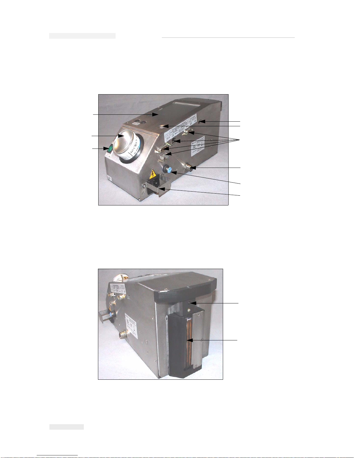
Main Parts
Figure 1-1 and Figure 1-2 show the printer with the main components and
connections highlighted.
Figure 1-1: Printer Parts
1. USB Port
2. Printer Status LED
3. I/O, Ethernet and Communications
Connectors
4. Remote Product Sensor Connector
5. Air Pipe Connector
6. Main Power Inlet
7. Power Switch
8. Ink Canister
9. CLARiTY Operator Interface
1
3
4
5
6
7
8
9
2
1
Figure 1-2: Printhead
1. Internal Product Sensor
2. Printhead
2
Page 11

Rev AB Introduction 2-1
2
Safety
This chapter contains the following topics:
•Introduction
• Safety conventions used in this manual
• Equipment safety guidelines
• Placement of the printer
• Ink safety guidelines
• Safety Warnings for126/380/500 printers
• Medical emergencies
Caution
Read this chapter thoroughly before attempting to install, operate,
service, or maintain this equipment.
Warning
The intended use of this printer is to print information directly onto
a product. Use of this equipment in any other purpose may lead to
serious personal injury.
Introduction
The policy of Interactive Coding Equipment is to manufacture non-contact
printing/coding systems and ink supplies that meet high standards of
performance and reliability. Therefore, we employ strict quality control
techniques to eliminate the potential for defects and hazards in our
products.
Page 12

Torus 126, 380 and 500 Operator Manual
2-2 Safety Conventions Used in the Manual
Rev AB
The safety guidelines provided in this chapter are intended to educate the
operator on all safety issues so that the operator can operate the printer
safely.
Safety Conventions Used in the Manual
Specific safety information is listed throughout this manual in the form of
Warning and Caution statements. Pay close attention to these statements
as they contain important information that help in avoiding potential
hazards to yourself or to the equipment.
Warning Statements
• Warning statements are used to indicate hazards or unsafe practices
that may result in personal injury or death
• They have a triangular symbol with an exclamation mark to the
immediate left of the text
• They are always preceded by the word “Warning”
• They are always found before the step or information referring to the
hazard
For example:
Warning
The next step, “Cleaning the Printhead,” must be performed by
service or maintenance personnel. Qualified personnel have
successfully completed the training courses, have sufficient
experience with the printer, and are aware of the potential hazards
to which they are exposed.
Caution Statements
• Caution statements are used to indicate hazards or unsafe practices
that can result in equipment or property damage
• They have a triangular symbol with an exclamation mark to the
immediate left of the text
• They are always preceded by the word “Caution”
• They are always found before the step or information referring to the
hazard
Page 13
Torus 126, 380 and 500 Operator Manual
Rev AB Equipment Safety Guidelines 2-3
Example:
Caution
Never turn off the printer by switching the AC power switch to the
Off (O) position. Before pressing the Off key, allow the printer to
complete the three and a half minute shutdown sequence. Failure in
following this procedure prevents the printer from drawing the ink
in the ink return line, back into the reservoir. This may cause the ink
to dry in the ink return line, resulting in problems when you turn the
printer on again.
Equipment Safety Guidelines
This section contains important safety guidelines pertaining to the
operation and handling of the printer and associated equipment.
Warning
Always observe the following safety guidelines when operating and
handling the printer and associated equipment.
Comply with Electrical Codes
All electrical wiring and connections must comply with
applicable local codes. Consult the appropriate
regulatory agency for further information.
Avoid Breathing Exhaust Vapors
During this operation, the printer releases fumes from
the printer exhaust tube. These fumes may be flammable
and cause a health hazard. Therefore, do not allow the
exhaust to be confined to an area that does not have
proper ventilation, or be located near a source of
ignition. Printer exhaust fumes are generally heavier
than air, so keep all sources of ignition away from low
Page 14

Torus 126, 380 and 500 Operator Manual
2-4 Placement of the Printer
Rev AB
areas where fumes may travel or accumulate.
If, under any circumstances, the printer is to be kept in a place that lacks
proper ventilation, it is necessary to expel the printer exhaust to outside
air. Consult the appropriate regulatory agency concerned with the
emission permit and venting system requirements, before giving vent to
the printer exhaust into the outside air.
Note: A Vapor Exhaust Ducting Kit is available at Interactive Coding
Equipment.
Do Not Remove Warning Labels
Do not, under any circumstances, remove or obstruct
any warning, caution, or instruction labels present on
the printer.
Placement of the Printer
Warning
Do not place the printer in a hazardous location. Hazardous
locations might create an explosion, leading to personal injury.
Hazardous locations, as defined in the United States, are those areas that
may contain hazardous materials in a quantity sufficient to create an
explosion. These are defined in Article 500 of the National Electrical Code
ANSI/NFPA 70–1993.
Outside the United States, you must ensure compliance with all local
regulations regarding equipment placement in potentially hazardous
locations.
Ink Safety Guidelines
This section provides important safety guidelines pertaining to the use
and handling of printer supplies (inks, make-up fluids, and cleaning
solutions).
Page 15
Torus 126, 380 and 500 Operator Manual
Rev AB Ink Safety Guidelines 2-5
Warning
Always observe the following safety guidelines when using or
handling inks, make-up fluids, and cleaning solutions.
For continued protection against possible fire hazard, use only ICE
supplies with a flash point no lower than -22 °C (-8 °F) and boiling
point no lower than 56 °C (133 °F).
No Smoking
Do not smoke when you are near the printer or
printhead. If the printer exhaust fumes are subjected to
an ignition source, it may result in an explosion or fire.
Wear Safety Glasses
Wear safety glasses with side shields (or equivalent eye
protection) when handling any ink, make-up fluid, or
cleaning solution. If it splashes on your eyes, flush your
eyes with water for 15 minutes and consult a physician
immediately.
Avoid Skin Contact
Wear butyl rubber gloves when handling any ink,
make-up fluid, or cleaning solution. Avoid contact with
skin and mucous membranes (nasal passage, throat).
Upon contact with skin, remove any contaminated
clothing and wash the area with soap and water.
Consult a physician if irritation persists.
Avoid Breathing in the Vapors
Avoid prolonged exposure to print exhaust vapors. If
respiratory protection is needed, a cartridge organic
respirator can be used.
Page 16
Torus 126, 380 and 500 Operator Manual
2-6 Ink Safety Guidelines
Rev AB
Dispose Ink Properly
Do not pour any ink, make-up fluid, or cleaning solution
into sinks, sewers, or drains. Waste disposal must
comply with local regulations. Contact the appropriate
regulatory agency for further information.
Read the Material Safety Data Sheets
Read and understand the Material Safety Data Sheet
(MSDS) before using any ink, make-up fluid, or cleaning
solution. An MSDS exists for each type of ink, make-up
fluid, and cleaning solution. The appropriate sheet or
sheets are supplied along with the shipped product.
Ensure that you retain all MSDSs for future reference in
case you need to consult a physician regarding an ink-related accident.
Additional copies of MSDSs are available upon request, and can be
obtained by contacting the ICE Customer Service Department at 800–
843–3610. Outside the U.S., customers should contact a subsidiary ICE
office or their local ICE distributor.
Store Inks Properly
Certain inks, make-up fluids, and cleaning solutions are
flammable and must be stored appropriately. Storage
must comply with local regulations. Contact the
appropriate regulatory agency for further information.
The label on the bottle or the MSDS indicates if a
particular fluid is flammable or not.
Caution
The waste container or service tray ground to the printhead must be
made of metal. Use of a non-metallic waste container/service tray
may result in the possibility of electrostatic discharge.
Page 17

Torus 126, 380 and 500 Operator Manual
Rev AB Safety Warnings for 126, 380 and 500 Printers 2-7
Safety Warnings for 126, 380 and 500 Printers
Some additional warnings that are specific to the 126, 380 and 500 printers
are described in this section.
Warning
Before opening or removing any printer covers, ensure that the
mains power is disconnected and compressed air supplies are
switched off.
Warning
This equipment must be installed with a locally positioned mains
supply isolation device. This can be either a plug and socket or a
switch disconnector or circuit breaker in accordance with IEC 609473 or IEC 60947-2.
Warning
Always isolate equipment from the mains and remove mains power
connector to the printer before attempting any maintenance or repair
on any part of the product.
Warning
Before connecting compressed air supply to Torus 126, 380 and 500,
ensure the air regulator adjustment knob has been turned fully anticlockwise.
Warning
Ensure that any cables from the printer are secured to avoid chance
of movement into walkways and becoming a trip hazard.
Page 18

Torus 126, 380 and 500 Operator Manual
2-8 Safety Warnings for 126, 380 and 500 Printers
Rev AB
Warning
Do not point the printhead directly and in close proximity to the
eyes, unless the printer is switched off and isolated from the mains
and compressed air supplies.
Warning
The printer uses an operator control console mounted on the top of
the unit. Ensure that this panel is at a height where access and use is
least restricted.
Warning
Regard any warning or hazard information supplied with any
cleaning fluid or consumable products. When using any chemicals,
always wear protective gloves and only use in well-ventilated areas.
Warning
There will be sections of the 602004 Torus 126, 380 and 500 control
board that will be permanently powered via the on-board lithium
battery - therefore it is essential that the board should never be
placed onto nor stored in or on any conductive surface (including
conductive, plastic bags etc.) as this would flatten the battery and/or
potentially result in battery overheating.
Warning
The Torus 126, 380 and 500 printer is supplied with warning
symbols for power supply and compressed air. If any part of these
symbols become damaged, worn or removed they must be
immediately replaced.
Page 19

Torus 126, 380 and 500 Operator Manual
Rev AB Medical Emergencies 2-9
Warning
Ensure that all external energy sources are isolated from the printer
before opening the outer casing. This includes the mains power
cable and I/O cable assembly (if used).
Warning
When you replace an old battery with a new battery, make sure to
use the correct type of battery. The failure to follow this warning can
cause injury or explosion.
Warning
Dispose the used batteries according to the local regulations. Replace
with the correct type of battery. The failure to follow this warning
can cause injury or explosion.
Medical Emergencies
This section provides important medical information in case of an
accident.
Warning
In the event of a medical emergency, contact a physician
immediately.
Emergencies Involving Printer Fluids
If the incident involves an ink, make-up fluid, or cleaning solution, carry
the bottle and/or MSDS with you to the physician’s office. These items
contain important information that the physician may require, to provide
the precise medical treatment.
Page 20

Torus 126, 380 and 500 Operator Manual
2-10 Medical Emergencies
Rev AB
Rocky Mountain Poison Control Center
All of ICE inks, make-up fluids, and cleaning solutions are also registered
with the Rocky Mountain Poison Control Center, located in the United
States. If the bottle or MSDS cannot be located, the physician can contact
the Rocky Mountain Poison Control Center to obtain the information
required.
Rocky Mountain Poison Control Center
(303) 623-5716
Note: Persons outside the United States requiring medical attention can have a
physician contact the Rocky Mountain Poison Control Center in the United
States or a poison control center or hospital in their own area.
Page 21

Rev AB Introduction 3-1
3
CLARiTY™ Operator
Interface
This chapter contains the following topics:
• Home Page of CLARiTY™
• Screen Description
• Data Entry Pad
Introduction
The CLARiTY™ operator interface is a touch screen system. The icons in
the interface help the operator to navigate through the software easily.
Normally most areas of the interface are active. The operator can touch the
active areas to select the required feature. The interface also contains the
icons that are like buttons on the normal control panel (for example,
).
Page 22

Torus 126, 380 and 500 Operator Manual
3-2 Home Page of CLARiTY™
Rev AB
Home Page of CLARiTY™
The Home Page of the CLARITY™ is shown in Figure 3-1.
Screen Description
Icons
The screen has icons that help you navigate to the key pages of the
interface. You can reach any key page from the current page with these
icons (Refer to Figure 3-2 and Table 3-1).
Figure 3-1: Home Page of CLARiTY™
Page 23

Torus 126, 380 and 500 Operator Manual
Rev AB Screen Description 3-3
Control Icons
You can use the control icons to get control on the printer immediately
(refer to Figure 3-3).
Icon Description
Home Takes you to the Home page
Status
Window
Takes you to the Fault and Warning pages
Tools Takes you to the Setup an d Diag n os tics Tools page
Scroll Bar Allows to navigate up and down the screen selected. This icon
is useful to find a Job in the Torus 126, 380 and 500 database.
Control
icons
Refer to “Control Icons” on page 3-3.
Job Use to load the next image (job) for printing and to enter any
variable data
Navigation
Bar
Indicates the location of your current screen in the menu tree
The current screen allows you to do the following tasks:
• Touch the Back icon to return one level up
• Touch any level displayed on the Navigation Bar to take
you to that level
Table 3-1: Shortcut Icons
Figure 3-2: Shortcut Icons
Status Window
Tools Icon
Back Icon
Scroll Bar
Down Icon
Navigation Bar
Home Icon
Control
Icons
Up Icon
Print Icon
Page 24

Torus 126, 380 and 500 Operator Manual
3-4 Screen Description
Rev AB
Active Areas
The Production Performance and Consumables areas in Figure 3-4 take you to
the screens that have more information and statistics.
Figure 3-3: Control Frame Icons
Stop
Run
Start-up/Shut Down
Figure 3-4: Performance and Consumables Status
Consumables
Production Performance
Active Area
Page 25

Torus 126, 380 and 500 Operator Manual
Rev AB Data Entry Pad 3-5
Data Entry Pad
An alphanumeric, mobile phone style data entry pad is provided to the
operator to enter the data in the CLARiTY™ interface.
The different keys in the data entry pad are shown in Table 3-2.
Key Characters (in turn)
1.,?/:!-&;+#()'"_@$¢£€¥%<>¿¡§=¤
ABC2abcДАБВГЕЖЗдабвгежз¢
DEF3defИЙЛКийлк€
GHI4ghiОМНомн
JKL5jkl£
MNO6mnoЦФТУШСцфтушс
Table 3-2: Data Entry Pad Map - English (Default)
Figure 3-5: Data Entry Pad
Page 26

Torus 126, 380 and 500 Operator Manual
3-6 Data Entry Pad
Rev AB
PQRS7pqrs$ß\
TUV8tuvЬЩЫЪьщыъ
WXYZ9wxyz
Cursor left
0*
Cursor right
Backspace/Clear
Space
Key Characters (in turn)
Table 3-2: Data Entry Pad Map - English (Default) (Continued)
Page 27

Rev AB Turn on the Printer 4-1
4
Equipment Operation
This chapter describes the procedures to do the following tasks:
• Turn on the printer
• Set the air pressure
• Start the printer
• Printer LED Functions
• Add the ink
• Get High quality print
• Clean the printhead
Turn on the Printer
Press the power switch on the rear of the unit to turn on the printer (refer
to Figure 4-1).
Figure 4-1: Power Switch
Power Switch
Page 28

Torus 126, 380 and 500 Operator Manual
4-2 Turn on the Printer
Rev AB
The sequence of steps that occur after you turn on the printer are as
follows:
1 During the startup sequence, the printer performs a number of self-
diagnostic checks. These checks take approximately 90 seconds to
complete.
2 During the self-diagnostic checks, the CLARiTY™ interface screen
shows the first set of diagnostic data. Ignore this data.
3 When the self-diagnostic checks are complete, the CLARiTY™ Home
Page appears (refer to
Figure 4-2).
4 The status window of the Home Page shows the SHUTDOWN status.
5 During the SHUTDOWN status, the Stop (red) and Run (green)
buttons (
Figure 4-2) are disabled (in grey color).
Note: If the print sensor is activated accidentally, the printer will not operate
because all the sensor and encoder input are ignored during the shutdown
status.
Note: During the shutdown status, make sure that the production line and
printer are prepared and ready for the shutdown.
Figure 4-2: Home Page
Stop(red)
Run(green)
Shutdown
Shutdown Status
Page 29

Torus 126, 380 and 500 Operator Manual
Rev AB Set the Air Pressure 4-3
Set the Air Pressure
The printer comes with an air regulator. During the installation of the
printer, the air regulator must be installed near the printer.
To increase the pressure, turn the air regulator control knob to the right
side. To decrease the pressure, turn the knob to the left side (Figure 4-3 on
page 4-4).
Caution
The air pressure must be set according to the printer type. Follow the
recommended values. The failure to follow this caution can decrease
the efficiency of the printer.
The air pressure requirement for the Torus 126/380/500 is shown in the
Table 4-1.
Printer Type Air Pressure
Torus 126 2.5 Bar
Torus 380 3.5 Bar
Torus 500 4.5 Bar
Table 4-1: Air Pressures
Page 30

Torus 126, 380 and 500 Operator Manual
4-4 Set the Air Pressure
Rev AB
Figure 4-3: Air Regulator
Control Knob
Page 31

Torus 126, 380 and 500 Operator Manual
Rev AB Start the Printer 4-5
Start the Printer
Touch the Start-Up/Shutdown icon to start the printer.
The events that occur after you touch the Start-Up/Shutdown icon are as
follows:
•The Offline status appears in the status window of the CLARiTY™
Home Page (refer to
Figure 4-4).
•The Stop and Run buttons become active (Figure 4-4).
• If a fault or a warning condition exists, a fault or warning message
appears in the status window instead of the Offline status. You must
clear the fault or warning message before you continue the process of
printing.
Refer to “Warnings and Fault Messages” on page 5-14 for more
information on Fault and Warning messages.
Figure 4-4: Home Page - Offline
Startup/Shutdown
Offline Status
Page 32

Torus 126, 380 and 500 Operator Manual
4-6 Printer LED Functions
Rev AB
Printer LED Functions
The printer has a dual colored LED below the CLARiTY™ interface that
indicates the status of the printer (Figure 4-5).
The LED states and their functions are shown in Table 4-2.
Add Ink
This section describes the following topics:
• How to review the status of the ink
• Correct time to insert a new ink canister
• The number of prints possible with the available ink
Review the Ink Status
The Consumables area of the Home Page screen displays a percentage
value of ink that is left in the ink canister of the printer. For example refer
to Figure 4-6 on page 4-7.
LED States Function
Green (constant) On-line, ready to print
Green (flashing) On-line and printing (LED flashes
for every print)
Orange (Flashing) CLARiTY update in progress
Red (constant) Off-line
Red (flashing) Fault condition
Table 4-2: LED Status and their Functions
Figure 4-5: Printer LED
Printer Status LED
Page 33

Torus 126, 380 and 500 Operator Manual
Rev AB Add Ink 4-7
A description of the colors that appear in the status bar is as follows:
Insert a New Ink Canister
The ink must be added when the ink low level warning appears on the
CLARiTY™ screen. The ink status bar must show less than 5% (Figure 4-
6). The ink status shown on the status bar makes sure that the present ink
canister is replaced after the present canister becomes empty.
When the consumables meter status is red before a new canister is fitted,
the printer will go through a longer filling cycle before the printing
continues.
Color Description
Blue The reservoir is full and replacement ink canister is not required
Yellow Enough ink is available for printing but you can add a new ink
canister. If a new ink canister is not added, the printer operates
until the printhead ink reservoir reaches a critically low level.
Red The ink canister is empty. A new ink canister must be added
and the ink empty fault must be cleared.
Table 4-3: Colors in the Consumables Status Area
Figure 4-6: Consumables Area
Consumables Area
Ink Status
Page 34

Torus 126, 380 and 500 Operator Manual
4-8 Add Ink
Rev AB
The ink type required for the type of printer is shown in the Table 4-4.
Do the following tasks to replace an empty ink canister with a new
canister:
1 Touch the Consumables area on the Home Page (Figure 4-6 on page 4-7).
The Consumables page appears (Figure 4-7).
2 Touch the Add Ink icon (Figure 4-7). The Add Ink screen appears
(Figure 4-8 on page 4-9).
Printer Ink Type (for a
175ml Ink Can)
Ink Type (for a
365ml Ink Can)
Torus 126 M512 NA
Torus 380 M512 M512-K
Torus 500 M512 M512-K
Table 4-4: Ink Types
Figure 4-7: Consumables Screen
Add Ink Icon
Page 35

Torus 126, 380 and 500 Operator Manual
Rev AB Add Ink 4-9
3 Enter the unique ink canister code found on the label of the every ink
canister (
Figure 4-9 on page 4-9) and touch the OK icon.
If you enter a wrong ink canister code, an error message appears (4-
10). Enter the correct ink canister code.
Figure 4-8: Add Ink Screen
Figure 4-9: Canister Code
Ink Canister Code
Page 36

Torus 126, 380 and 500 Operator Manual
4-10 Add Ink
Rev AB
Warning
EQUIPMENT DAMAGE. The use of incompatible ink can seriously
damage the printer and such damage will not be covered under
warranty.
4 After the CLARiTY™ validates the new ink canister code, you can
replace the empty canister with a new canister. To fit the new canister
do the following tasks:
a. Turn the empty canister to the left side and remove the canister
from the canister chute (
Figure 4-11 on page 4-11).
Figure 4-10: Invalid Ink Code Messages
Page 37

Torus 126, 380 and 500 Operator Manual
Rev AB Add Ink 4-11
5 Remove the protective cover from the new ink canister.
6 Align the new canister into the canister chute and turn to your right
(
Figure 4-12).
7 Insert and set the new canister inside the chute carefully. Do not
overtighten.
Note: When you must refit a half full ink canister, the ink canister code must
be entered again.
Figure 4-11: Removal of Empty Ink Canister
Canister Chute
Figure 4-12: Direction of Insertion
Page 38

Torus 126, 380 and 500 Operator Manual
4-12 Add Ink
Rev AB
Capacity of the Ink Canisters
Do the following tasks to check the amount of ink that is available in the
current ink canister:
1 Touch the Consumables area on the Home Page screen during the
printer Running status (
Figure 4-13). The Consumables screen that
displays the number of prints (Figure 4-14 on page 4-13) appears.
This screen displays Prints Per Ink Canister and Prints Left in Canister.
The Prints Per Ink Canister gives the number of prints from a full ink
canister and Prints Left in Canister gives the number of prints left from
the current canister.
2 When a new job is selected, the number of prints is calculated again
and displayed on the screen. This number of prints depends on the
amount of ink the new image requires.
Figure 4-13: Consumables Area - Running
Consumables Area
Running Status
Page 39

Torus 126, 380 and 500 Operator Manual
Rev AB Add Ink 4-13
3 Use the Up and Down buttons to see the Estimated Empty Time and
Estimated Time Remaining for the current ink canister (
Figure 4-15 on
page 4-13).
Figure 4-14: Number of Prints
Prints from a full
Prints Left from the
Current Canister
Ink Canister
Figure 4-15: Estimated Time Display
Estimated Canister
Estimated Time Left
for Present Ink Canister.
Empty Time
Up Icon
Down Icon
Page 40

Torus 126, 380 and 500 Operator Manual
4-14 How to Get High Quality Print
Rev AB
How to Get High Quality Print
To get high quality print, make sure to move the products past the
printhead in a consistent method. For correct conveyor movement, refer to
the following guidelines:
• A high grip and flat belt conveyor with pack guidance is
recommended.
• Make sure that there is enough space between the products to get
correct print signals. This action prevents the products from not being
printed.
• Gravity roller conveyors are not recommended. The box speed and
spacing can change according to the product speed and weight.
• Powered roller conveyors can decrease the print quality. This type of
roller is not recommended for barcodes or high resolution graphic
applications.
• If the barcodes are required in the image, then an encoder must
measure accurately the speed of the product. This accuracy in the
speed measurement leads to best print performance.
The maximum and minimum conveyor speeds for Torus 126/380/500 are
shown in Table 4-5.
The most common causes for low quality of print are described below:
• Incorrect movement of the product past the printhead (for example
the use of gravity conveyors, roller conveyors)
• Dust or dirt blocking or deflecting jets
• Slippage of the product on the conveyor
• The distance between the face of the printhead and the printed surface
is not consistent. This difference is caused normally because of the
following reasons:
- The product guidance (product handling) is not enough.
- The product is distorted (for example, bent cardboard box).
Printer Type Minimu m Speed Maximum Speed
Torus 126 10 mm/second
(0.6 m/min)
550 mm/second
(33 m/min)
Torus 380 10 mm/second
(0.6 m/min)
550 mm/second
(33 m/min)
Torus 500 10 mm/second
(0.6 m/min)
550 mm/second
(33 m/min)
Table 4-5: Conveyor Speeds
Page 41

Torus 126, 380 and 500 Operator Manual
Rev AB Clean the Printhead 4-15
Note: To get high quality prints, the distance between the printhead and the
product must not be greater than 2mm (
Figure 4-16 on page 4-15). Use the
pack guidance on the conveying equipment to maintain this distance.
Note: The Delrin guide on the front side of the printer helps to protect the
printhead from any potential damage and to maintain the jetting distance to
the product.
Clean the Printhead
The 126/380/500 printhead does not require the operator to clean or
prime at normal intervals because this printer is an auto-purging printer.
If the print quality decreases, the A and B buttons on the printer provide
additional functions to clean the printer further (refer to Figure 4-17 on
page 4-16).
Box Distance < 2mm
Figure 4-16: Box Distance
Page 42

Torus 126, 380 and 500 Operator Manual
4-16 Clean the Printhead
Rev AB
Button 'A'
Caution
Do not touch or remove the nozzle plate or the jetting face of the
printhead under any condition while you perform the procedures in
this section (refer to
Figure 4-18 on page 4-17 and Figure 4-19 on
page 4-18).
When you can see bands of missing print across the print, the quality of
the print has decreased and not acceptable standard. You must press
button A in this condition.
You can use the button for the following two purposes:
• Press the button for one second, then release to start the sequence of
controlled purge.
A small quantity of ink that removes the dirt from the jetting orifices is
purged through the printhead.
• Press and hold the button to activate a longer cleaning cycle. When
the cycle begins, release the button A.
Note: This cycle must be used when shorter operation to clean the printer
does not remove the blocks in the jets.
Figure 4-17: A and B Buttons
Page 43

Torus 126, 380 and 500 Operator Manual
Rev AB Clean the Printhead 4-17
A larger quantity of ink that washes the printhead face is purged
through the printhead jets. Then an air blast is used to removes excess
ink.
Button 'B'
When you press the button 'B', the system uses the air to clear away any
contamination on the printhead faceplate.
Press and hold the button B for some seconds to clean the printhead
faceplate completely of any ink and dirt.
This method is best to remove any dirt following a visual inspection of the
printhead.
Basic Maintenance
When the printer is operated in dirty environments, the operator must
clean around the jetting face of the printer (refer to the Figure 4-19 on
page 4-18). This process maintains the efficiency of the ink return system.
The failure to perform this basic maintenance can cause the loss of ink.
Basic maintenance includes the removal of dirt that closes the clearance
between the nozzle plate and the front plate. This process must be
performed as necessary.
Figure 4-18: Printhead Nozzle Plate
Printhead
Nozzle Plate
Page 44

Torus 126, 380 and 500 Operator Manual
4-18 Clean the Printhead
Rev AB
Figure 4-19: Printhead Jetting Face
1. Printhead Nozzle Plate
2. Blow Nozzle Plate
3. Ink Collector
4. Knife Edge
5. Ink Drain Channel
6. Printhead Front Plate
1
2
3
4
5
6
Page 45

Rev AB Select a Job for Printing 5-1
5
Software Operations
This chapter contains the following topics:
• Select a Job for Printing
• Variable Information
• Information about Current Job
• Enable or Disable the Print (On-Line/Off-Line)
• Print Position Adjustment
• Self Cleaning Frequency of Operation
• Warnings and Fault Messages
• Set the Correct Time and Date
• Select the Correct Language
Select a Job for Printing
Introduction
When the printer is in Running, Offline or in the Shutdown status, you can
select a new print image or job. You can select, edit and see the image on
the WYSIWYG display before printing the image.
Touch the OK icon to replace the current image with the new job.
If you must cancel the process of job selection, touch the Cancel button or
the Home button (refer to Figure 5-6 on page 5-5).
Procedure
To select a job for printing, do the following tasks:
1 Touch the Job icon (Figure 5-1 on page 5-2).
A Job List screen with the different jobs stored in the local memory is
displayed (
Figure 5-2 on page 5-2).
Page 46

Torus 126, 380 and 500 Operator Manual
5-2 Select a Job for Printing
Rev AB
Figure 5-1: Job Icon
Job
Home
Figure 5-2: List of Jobs
List of Jobs
Page 47

Torus 126, 380 and 500 Operator Manual
Rev AB Select a Job for Printing 5-3
2 If the job list is short, then Touch the job name and the name of the job
is highlighted (
Figure 5-3).
3 If the job database is large to fit into the screen, you can select the job
in two methods:
• A scroll bar appears (Figure 5-4 on page 5-4). The scroll bar helps you
move up and down the database to see all the jobs and select the
required job.
•Touch the Data Entry Pad icon (Figure 5-4 on page 5-4). The Job Select
screen appears with a data entry keypad (like a mobile phone). The
job name is completed automatically as you begin to enter the
characters in the job name until you select the required job (
Figure 5-3
on page 5-3).
Job Highlighted
Figure 5-3: Job Selection
Page 48

Torus 126, 380 and 500 Operator Manual
5-4 Select a Job for Printing
Rev AB
Figure 5-4: Scroll Bar
Scroll Bar
Data Entry Pad
Figure 5-5: Job Selection Screens
Page 49

Torus 126, 380 and 500 Operator Manual
Rev AB Variable Information 5-5
4 When you select the required job, the CLARiTY™ displays a print
preview of the selected job (
Figure 5-6).
5 Touch the OK icon after the information displayed is correct (Figure 5-
6). The printer starts printing the job.
6 If your job contains variable information, refer to “How to Change
Variable Information” on page 5-6 for more information.
Variable Information
Introduction
If there are Job Variables (variable information fields) like a Batch Code on
the selected Job, CLARiTY™ prompts to edit or enter these fields.
If there are any variable TEXT fields, CLARiTY™ displays them first.
The check box at the side of variable fields indicates the fields that are
entered and fields that are not entered (Figure 5-7 on page 5-6).
A checkmark is added to the check box as you edit or enter the data in the
CLARiTY™. When all the boxes have a checkmark, you can continue to
the next step.
To select the Job variable you require to change, touch the related prompt.
This variable gets highlighted and display the default data in the data
window (Figure 5-7 on page 5-6).
Figure 5-6: Job Preview
Cancel
OK
Page 50

Torus 126, 380 and 500 Operator Manual
5-6 Variable Information
Rev AB
To change the variable text, touch the data window and use the data entry
keypad.
The Figure 5-7 shows the Job Variables for the job BBE1 and there is a
DATE field variable only (for use as a Best Before End Date).
How to Change Variable Information
Do the following tasks to change the default data for the DATE field
variable in the Job BBE1:
1 If the default date displayed in the data window (11 March 2004) is
correct, touch the OK icon and this date is printed (
Figure 5-7).
Figure 5-7: Job Variables
Data Window
Prompt
Checkbox
OK
Page 51

Torus 126, 380 and 500 Operator Manual
Rev AB Variable Information 5-7
2 Touch the data window or the data entry pad to move to the calendar
screen if you want to change the date information (
Figure 5-8).
• To change the month and the year, touch the and icons until
the correct month, and year is reached.
• To select a day of the month, touch the date.
Note: The red box in Figure 5-8 displays the current date and the blue
background displays the date selected for printing. The dates that are not
available for selection are in grey box.
3 Touch the OK icon and the data information is changed. If you have
many dates in your Job, repeat the steps one and two for each date.
4 The CLARiTY™ automatically returns to the Job variables list where
the check box for the date field is checked (
Figure 5-9 on page 5-8).
Figure 5-8: Calendar Screen
Page 52

Torus 126, 380 and 500 Operator Manual
5-8 Variable Information
Rev AB
5 Touch the OK icon and continue to the WYSIWYG Preview screen
(
Figure 5-10). Use the Zoom icon to see a bigger image.
6 Check the Job for correct data and touch the OK icon.
The printer prints all the products with the new job information.
You can touch the OK icon else, you can touch the Cancel icon or the
Home icon to return to the start.
Figure 5-9: Checked Box
Figure 5-10: Preview
Page 53

Torus 126, 380 and 500 Operator Manual
Rev AB Information about Current Job 5-9
Information about Current Job
The Home Page displays the name of the current job (Figure 5-11). Touch
the job name on the screen and the WYSIWYG information of the job is
displayed.
The example below displays the job that the 126, 380 and 500 printer is
printing. The job is shown in the WYSIWYG display (Figure 5-12). Use the
Zoom icon to see a bigger image.
Touch the Back or Home icon to return to the Home Page (Figure 5-12).
Figure 5-11: Job Name
Figure 5-12: Zoom Button
Zoom
Back
Home
Job
Page 54

Torus 126, 380 and 500 Operator Manual
5-10 Enable or Disable the Print (On-Line/Off-Line)
Rev AB
Enable or Disable the Print (On-Line/Off-Line)
To enable the printer, touch the Run (green) icon and the printer status bar
changes to Running status (Figure 5-13).
To disable the printer, touch the Stop (red) button (Figure 5-13) and the
printer status bar returns to Offline status.
Note: If the print sensor is activated when the printer is in Offline status, the
printer will not operate.
Note: If the print sensor is activated when the printer is in Online status, the
printer starts the print and performs all activities normally.
When the printer is in Online or Offline status, you can perform the
following activities:
• Select a new job
• You can add the ink
• Examine the printer parameters
• Clean the printhead with the buttons A and B (“Clean the Printhead”
on page 4-15).
Figure 5-13: Enable and Disable Printing
Run
Stop
Page 55

Torus 126, 380 and 500 Operator Manual
Rev AB Print Position Adjustment 5-11
Print Position Adjustment
To adjust the position of the print with reference to the front edge of the
box, do the following tasks:
1 Navigate to Tools > Setup > Printhead in the Home Page. The Printhead
setup page appears (
Figure 5-14).
2 Touch the Registration Delay icon. Enter the new print position (in
millimeters) with the keypad (
Figure 5-15).
Follow any of the below methods to make the adjustments:
•Touch the and icons to make small adjustments in the
position.
• Touch the data entry pad icon and use the pad to enter a new number
(
Figure 5-16 on page 5-12).
• Enter the Min, Max or Default values (Figure 5-17 on page 5-13).
Figure 5-14: Printhead Setup Screen
Tools
Page 56

Torus 126, 380 and 500 Operator Manual
5-12 Print Position Adjustment
Rev AB
Figure 5-15: Registration Delay
Registration Delay
Data Entry Pad
Figure 5-16: Registration Delay - Keypad
Page 57

Torus 126, 380 and 500 Operator Manual
Rev AB Self Cleaning Frequency of Operation 5-13
3 Touch the OK icon to set the new position.
Note: Smaller values move the print closer to the front edge of the product.
Larger values move the print away from the front edge.
Self Cleaning Frequency of Operation
If a remote print sensor is used, the 126, 380 and 500 printer has the ability
to clean the printhead by itself before every box. The filter life is increased
to the maximum if the printer is set to clean the printhead every tenth box.
Note: During the cleaning operations, the ink is returned to the ink reservoir and
used again.
If the printer operates in a very dirty environment, the self cleaning cycle
must be performed more number of times. This process maintains good
print quality and the long life of the printhead.
The printer includes a parameter with the name Prints per Cleaning Cycle
that you can configure. The parameter helps to set the self cleaning cycle
according to the factory environment. The default value is set at 10.
Do the following tasks to enter the Prints per Cleaning Cycle value:
1 Navigate to Tools > Setup > Printhead and scroll below to reach the
Prints per Cleaning Cycle. Enter the required value (
Figure 5-18 on
page 5-14).
2 Touch the OK icon followed by the Home icon.
Figure 5-17: Min, Max and Default Values
Page 58

Torus 126, 380 and 500 Operator Manual
5-14 Warnings and Fault Messages
Rev AB
Warnings and Fault Messages
When a Warning or a Fault condition occurs, the CLARiTY™ displays the
related message at the top of the screen (Figure 5-19).
Figure 5-18: Prints per Cleaning Cycle
Figure 5-19: Warning Message
Page 59

Torus 126, 380 and 500 Operator Manual
Rev AB Warnings and Fault Messages 5-15
Warnings
The CLARiTY™ displays all the Warning messages with an amber color in
the background (Figure 5-19 on page 5-14). When in a Warning condition,
the printer continues to operates.
When you touch the Warning message area on CLARiTY™, instructions
to clear the message are displayed.
The Figure 5-20 shows the ink low warning and gives the instructions to
clear the Warning sign by replacement of the empty ink canister with a
new canister. Follow the instructions displayed on the screen to clear the
Warning.
Figure 5-20: Ink Low Warning
Page 60

Torus 126, 380 and 500 Operator Manual
5-16 Warnings and Fault Messages
Rev AB
Faults
The CLARiTY™ displays all the Fault messages with a red color in the
background (Figure 5-21 on page 5-16). During a Fault condition, the
printer does not operate until the Fault is cleared. You can see in Figure 521 that the ink canister is empty.
The printer Fault output changes the status of the printer. If you can link
the fault status to the production line then, the printer can stop the line.
The above interlock helps the customer to make sure that the printing is
done on all the products.
Note: The LED below the CLARiTY™ Operator screen flashes (red) until the
fault is cleared and the printer starts printing.
Touch the Fault message area and the CLARiTY™ screen displays some
instructions.
The example in Figure 5-22 on page 5-17 shows that there is no ink in the
printer. The instructions on the screen tells you how you can add a new
ink canister and clear the Fault on the CLARiTY™ screen (Figure 5-22 on
page 5-17).
Figure 5-21: Fault
Page 61

Torus 126, 380 and 500 Operator Manual
Rev AB Warnings and Fault Messages 5-17
When the Fault message is cleared, then the printer begins to print again.
Figure 5-22: Out of Ink Fault
Page 62

Torus 126, 380 and 500 Operator Manual
5-18 Set the Correct Time and Date
Rev AB
Set the Correct Time and Date
Do the following tasks to set the correct time and date at the CLARiTY™
screen:
1 Navigate to Tools > Setup > Control from the Home Page. The Control
Screen appears (
Figure 5-23).
2 Select the Date and Time from the list displayed (Figure 5-23).
3 Touch Date and the calendar page appears (Figure 5-24 on page 5-19).
4 Use the and icons to select the current month and year.
5 Touch and select the current date from the calendar.
6 Touch the OK button.
Figure 5-23: Control Screen
Date And Time
Page 63

Torus 126, 380 and 500 Operator Manual
Rev AB Set the Correct Time and Date 5-19
7 Touch the Time icon and the time page appears (Figure 5-25).
8 Use the and keys to set the Hours, Minutes and Seconds.
9 Touch the OK button.
10 Touch the Home icon to return to the Home Page.
Figure 5-24: Calendar Screen
Figure 5-25: Time
Page 64

Torus 126, 380 and 500 Operator Manual
5-20 Select the Correct Language
Rev AB
Select the Correct Language
The CLARiTY™ has the ability to display all pages in different languages
and date codes in the format for that country.
For example: Month Day Year for USA and Day Month Year for UK.
Do the following tasks to select the language:
1 Navigate to Tools > Setup > Control > Internationalisation and the
Internationalisation screen appears (
Figure 5-26).
The current language is displayed.
2 Touch the Language icon and select the language you require from the
list. The selected language is highlighted (
Figure 5-27).
Figure 5-26: Internationalisation Screen
Page 65

Torus 126, 380 and 500 Operator Manual
Rev AB Select the Correct Language 5-21
3 Touch the OK icon.
4 Select the Region/Country icon to select the region or the country
(
Figure 5-26 on page 5-20).
5 Select the region required (Figure 5-28) and touch the OK icon.
6 Touch the OK icon.
7 Touch the Home icon to return to the Home Page.
Figure 5-27: Language Selection
Figure 5-28: Region/Country
 Loading...