

Page 1
Operator & Parts Manual
Rider Auto Scrubber
www.icecompanies.com
RS26
RS28
RS32
INTELLIGENT CLEANING EQUIPMENT
8300004
REV.04 (03-2017)
Page 2
2
ICE RS26 / RS28 / RS32
OPERATOR MANUAL
HOW TO ORDER PARTS
Only use ICE Company supplied or equivalent parts. Parts and supplies may be ordered
online,by phone, by fax or by mail.
1. Identify the machine model.
2. Identify the machine serial number from the data label.
3. Ensure the proper serial number is used from the parts list.
4. Identify the part number and quantity.
Do not order by page or reference numbers.
5. Provide your name, company name, customer ID number,billing and shipping address,
phone number and purchase order number.
Please ll out at time of installation for future reference.
Model No.
Serial No.
Machine Options
Sales Rep.
Sales Rep. Phone No.
Customer ID Number
Installation Date
READ OPERATOR MANUAL CAREFULLY!
ICE Company Limited
XiangShi Road LiaoBu DongGuan GuangDong China
Tel: 0769 - 81869000
Fax:0769 - 81863000
Specifications and parts are subject to change without notice.
IMPORTANT: To ensure full warranty protection, please ll out & return
your warranty card.
PROTECT THE ENVIRONMENT
Please dispose of packaging materials,old machine components
such as batteries, hazardous uids, including antifreeze and oil, in an
environmentally safe way according to local waste disposal regulations.
Always remember to recycle.
Page 3

3
ICE RS26 / RS28 / RS32
OPERATOR MANUAL
TABLE OF CONTENTS
SAFETY PRECAUTIONS......................................................................................................4
MACHINE COMPONENTS................................................................................................5-6
MACHINE SETUP & INSTALLATION....................................................................................7
MACHINE OPERATION........................................................................................................8
WHILE OPERATING MACHINE............................................................................................9
TANK DRAINING.................................................................................................................10
BATTERY CHARGING........................................................................................................10
PREVENTATIVE MAINTENANCE.......................................................................................11
FAULT CODE AND ELIMINATE..........................................................................................12
TECHNICAL SPECIFICATION............................................................................................13
PARTS LIST..................................................................................................................14-39
WEAR AND TEAR PARTS...............................................................................................40
WIRING DIAGRAM.............................................................................................................41
Page 4
4
ICE RS26 / RS28 / RS32
OPERATOR MANUAL
SAFETY PRECAUTIONS
This machine is intended for commercial use. It
is designed exclusively to scrub hard oors in an
indoor environment and is not constructed for any
other use. Only use recommended accessories.
All operators shall read, understand and
exercise the following safety precautions:
1. Do not operate machine:
- Unless trained and authorized.
- Unless you have read and understand the
operators manual.
- In ammable or explosive areas.
- With brake disabled.
- If not in proper operating condition.
2. Before starting machine:
- Make sure all safety devices are in place
and operate properly.
- Check brakes and steering for proper
operation.
3. When using machine:
- Go slow on inclines and slippery surfaces.
- Follow all safety guidelines.
- Be very careful when using the machine in
reverse.
- Reduce speed when turning.
- Report and x any damage to machine prior
to operating it.
- Never allow children to play on or
around.
4. Before leaving or servicing machine:
- Stop on level surface.
- Turn off machine.
5. When servicing machine:
- Read operators manual thoroughly prior to
operating or servicing this machine.
- Use manufacturer supplied or approved
replacement parts.
- Secure machine with wheel blocks prior to
jacking the machine up.
- Use approved jack or hoist to safely elevate
the machine.
- Disconnect batteries prior to working on
machine.
- Wear gloves when handling batteries or
battery cables.
- Avoid any contact with battery acid
- Avoid moving parts. Do not wear loose tting
clothing while servicing machine.
WARNING: Batteries emit hydrogen
gas. Explosion or re can result from
hydrogen gas. Keep sparks and open
ames away! Keep battery compartment
open when charging.
WARNING: Flammable materials can
cause an explosion or re. Do not use
ammable materials in tanks.
WARNING: Flammable materials or
reactive metals can cause explosion or re.
Do not pick up.
Page 5
5
ICE RS26 / RS28 / RS32
OPERATOR MANUAL
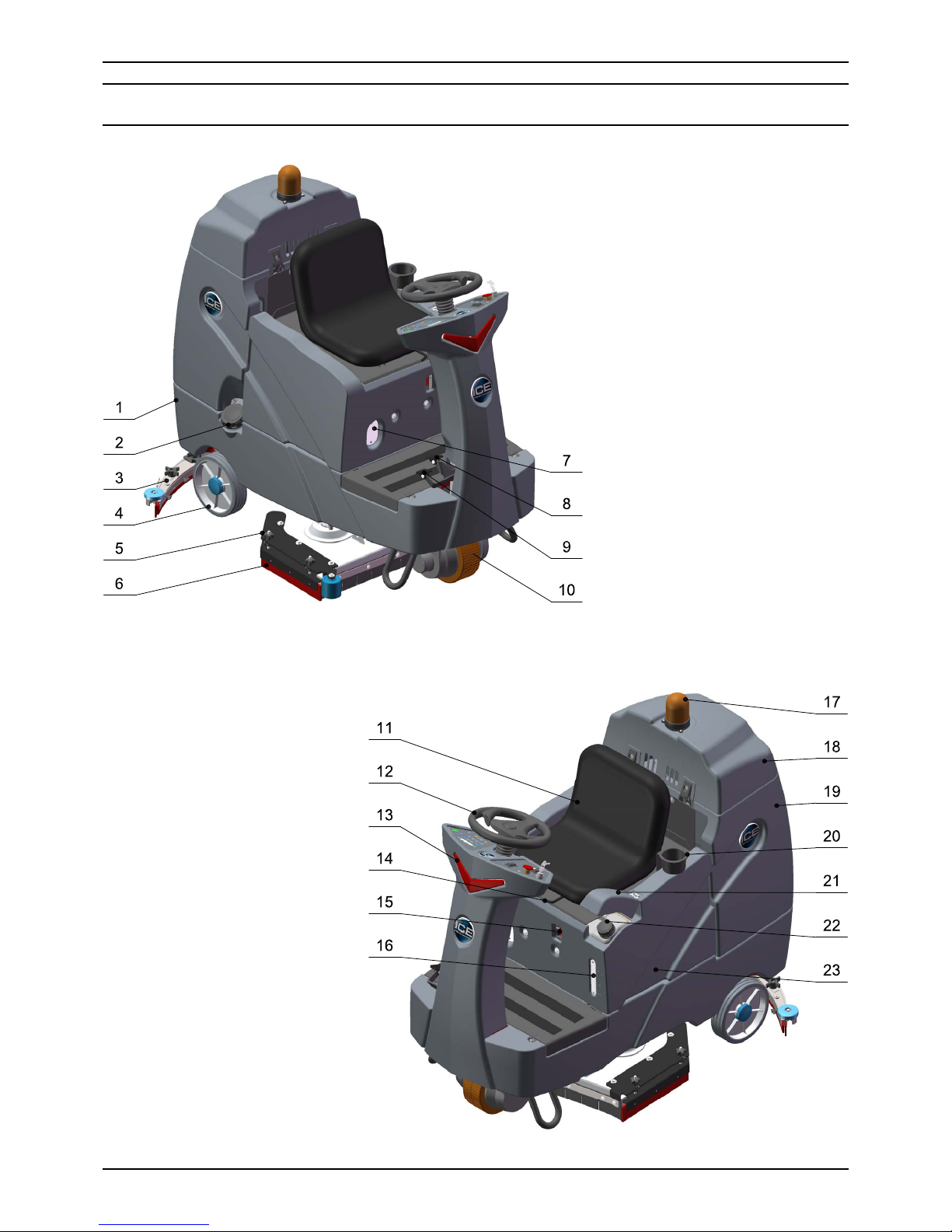
MACHINE COMPONENTS
1. Solution tank
2. Hose ll port & Cap
3. Squeegee assembly
4. Wheels, 10 inch
5. Scrub head assembly
6. Side squeegee assembly
7. Watching window, on-
board battery charger
8. Brake pedal
9. Propel pedal
10. Front drive wheel
11. Operator seat
12. Steering wheel
13. LED light, work
14. Adjusting handle, seat
15. Off-board battery
charger receptacle
16. Detergent level watching
window
17. Warning light
18. Recovery tank cover
19. Recovery tank
20. Cup holder
21. Cap
22. Detergent bottle
23. Battery box
Page 6
6
ICE RS26 / RS28 / RS32
OPERATOR MANUAL
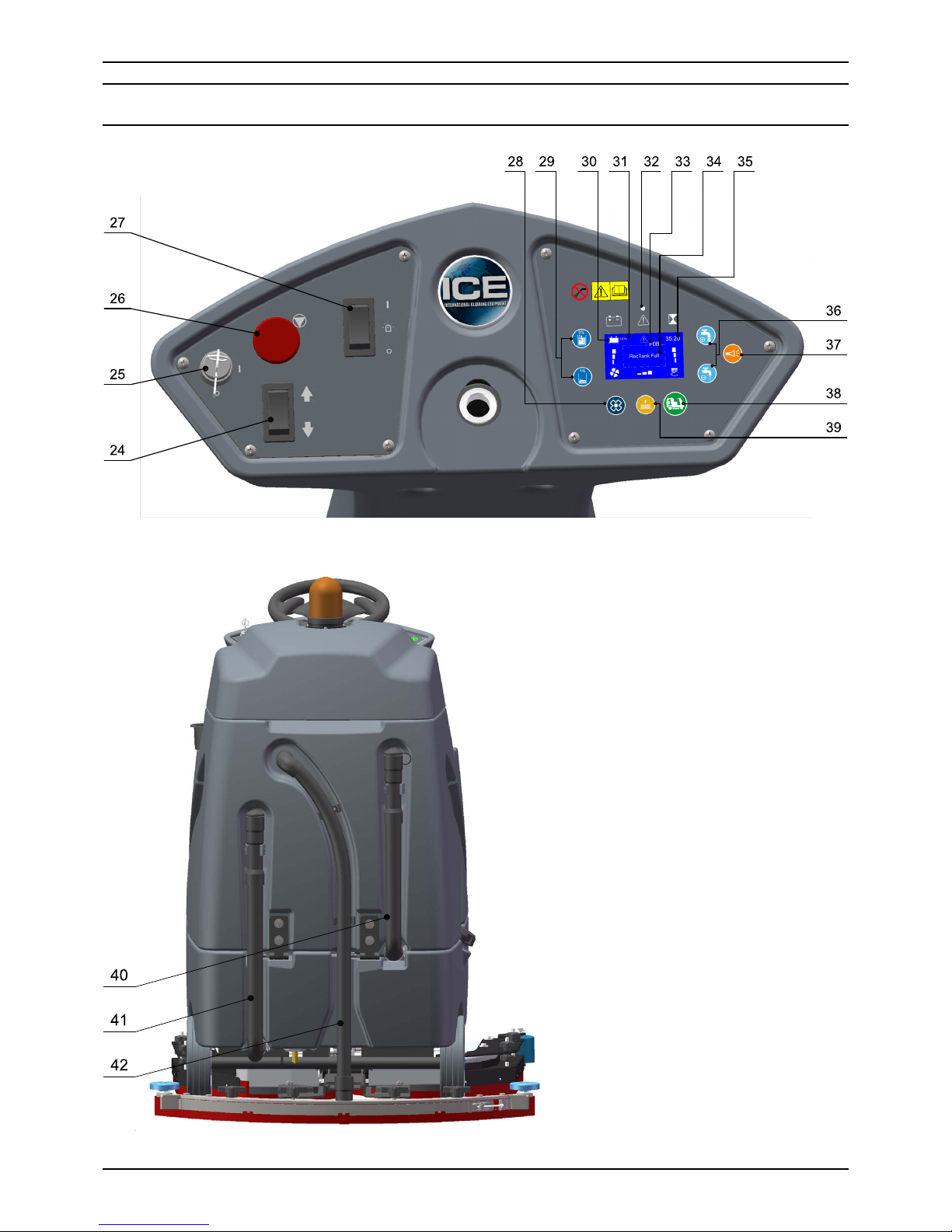
MACHINE COMPONENTS
24. Directional switch
25. Main power key switch
26. Emergency stop switch
27. Warning light switch
28. Vacuum motor switch & indicator
29. Detergent dosage adjusting
buttons & indicator
30. Batteries meter
31. LED display screen
32. Fault indicator
33. Fault code
34. Fault message
35. Hour meter
36. Solution ow adjusting buttons &
indicator
37. Horn button
38. 1-Step switch & Indicator
39. Brush pressure adjusting button
& indicator
40. Drain hose, recovery tank
41. Drain hose, solution tank
42. Vacuum hose
Page 7
7
ICE RS26 / RS28 / RS32
OPERATOR MANUAL
UNCRATING MACHINE
Be sure and check packing carton for any damage.
Immediately report any damage to carrier. Check
the contents of package to ensure that the
following items are included:
• Machine
• 4-6V Batteries
• Squeegee assembly
• 2-Pad drivers
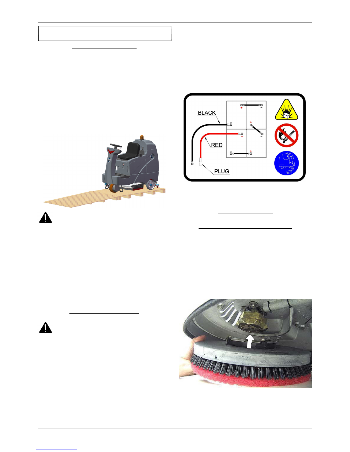
1. Uncrate the wooden box, place the top board
on the edge of pallet, lie in the front of the
machine, as below shown.
WARNING:
Do not operate machine unless
you have read & understood this manual.
2. Install batteries.(see INSTALLING BATTERIES)
3. Turn on the Main power key switch (machine
components, #25), make sure the Squeegee
assembly (machine components, #3) and the
Scrub head assembly (machine components,
#5) is off the oor.
4. Sit in the Operator seat (machine components,
#11), hold the Steering wheel (machine
components, #12), press the Propel pedal
(machine components, #9) and driving slowly
the machine down from the slope.
INSTALLING BATTERIES
WARNING: Batteries emit hydrogen gas.
Explosion or re can result from hydrogen
gas.Keep sparks and open ames away! Keep
battery compartment open when charging.
Recommended battery spec:
4-6V, 260AH@20HR deep cycle batteries.
Max. batteries dimensions :
300mm (L) X 180mm (W) X 290mm (H)
1. Turn the Main power key switch off.
2. Remove the Operator seat & the Battery box
(machine components, #23).
3. Carefully place the batteries into the
compartment as shown in gure below. Place
the battery brace at the rear of the batteries.
NOTE: Do not drop the batteries into the
compartment!
4. Connect battery cables to posts in numbered
order as shown in drawing below.
NOTE: RED to POSITIVE and BLACK to
NEGATIVE.
5. Reinstall the Operator seat and the Battery box.
MACHINE SET UP
INSTALLING BRUSHES OR PADS
1. Turn off the 1-Step switch (machine
components, #38) and raise the Scrub head
assembly off the oor, then stop machine on the
level surface, remove the key and ensure the
machine is turned off.
2. If using the pad driver, rst attach the
appropriate pad to the pad driver surface.
3. Align the pad driver or brush under the motor
hub and push it upward to engage.
4. To remove the pad driver or brush, raise the
scrub head and remove the Side squeegee
assembly (machine components, #6), push the
edge of brush downward.
MACHINE SET UP & INSTALLATION
Page 8
8
ICE RS26 / RS28 / RS32
OPERATOR MANUAL
MOUNTING THE SQUEEGEE ASSEMBLY
1. Turn off the 1-Step switch and raise the
Squeegee assembly off the oor.
2. Mount the squeegee assembly to the squeegee
pivot bracket. make sure the knobs are
completely seated into the slots before securing
knobs.
3. Connect the Vacuum hose (machine
components, #42) to the squeegee assembly.
Loop the hose by using the hose clip provided.
4. Check the squeegee blades for proper
adjustment.
FILLING THE SOLUTION TANK
The machine is equipped with a Hose ll-port
(machine components, #2) at the side of the
machine, and a bucket ll-port located under the
recovery tank.
NOTE: Before accessing the bucket ll-port
make sure that the recovery tank is empty.
When lling the solution tank with a bucket,
make sure that the bucket is clean. Do not use
the same bucket for lling and draining the
machine.
WARNING: Do not put any ammable
materials into solution tank. this can cause an
explosion or a re.
FILLING THE DETERGENT BOTTLE
The machine is equipped with a 6 liters Detergent
bottle (machine components, #22). Open the Cap
(machine components, #21) you can ll detergent,
and watch the liquid level on the Detergent level
watching window (machine components, #16).
The ratio of water and detergent is 0~5%, you can
adjust this ratio via pressing the Detergent dosage
adjusting buttons (machine components, #29).
NOTE: Only use recommended cleaning
chemicals. Contact your janitorial supply
distributor for recommendations on proper
chemicals.
WARNING: Do not operate machine
unless you have read and understand this
manual.
PRE-OPERATION CHECKS
1. Check the tank cover seals for damage.
2. Drain the recovery tank, check the vacuum fan
inlet lter, clean them if necessary.
3. Check the vacuum hose for debris or blockage.
4. Check the squeegees for damage, wear and for
deection adjustment.
5. Check whether Pad/Bruch is installed properly .
6. Check the brakes and steering for proper
operation.
OPERATION THE MACHINE
1. Sit in the Operator seat, adjusting the seat
to comfortable place by pushing the Seat
adjustment handle (machine components, #14).
NOTE: The machine will not travel unless the
operator is sitting in the operator seat.
2. Turn on the machine.
Check the LED display screen (machine
components, #31) , if there are fault codes
(machine components, #33) and the Fault
indicator (machine components, #32) is blink,
please Do Not operation the machine unless the
faults have been eliminated (please see FAULT
CODES AND ELIMINATE section).
3. Select the preferred settings by pressing the
Brush pressure adjusting buttons (machine
components, #39) , Solution ow adjusting
buttons (machine components, #36) and
Detergent dosage adjusting buttons.
NOTE: Use the minimal pressure and ow
as possible.
4. Turn on the 1-Step switch, the Scrub head
assembly and the Squeegee assembly will
lower down automatically, all the presetting
functions will turn on.
5. The machine can scrub in both forward and
backward, place the Directional switch (machine
components, #24) in the forward direction is to
move forward, backward is to move backward.
The horn will sound and the squeegee will
raise automatically (the vacuum motor will turn
off after a short delay) when drive machine
backwards. This is to prevents damaging the
squeegee.
NOTE: Go slow when drive machine
backwards.
MACHINE OPERATION
Page 9

9
ICE RS26 / RS28 / RS32
OPERATOR MANUAL
6. Press the Propel pedal, the machine start
scrubbing, the speed can be adjusted by
controlling the force of foot stepping, light is
slow, heavy is fast.
NOTE: Go slow on inclines and slippery
surfaces.
7. To stop scrubbing, turn off the 1-Step switch,
the scrub head will raise automatically, the
squeegee will also raise after a short delay (the
vacuum indicator ashing), please keep moving
until the dirty water is picked up, and then
release the propel pedal and stop scrubbing.
8. Turn off the machine.
BRAKE DEVICE
The machine is drived by the Front drive wheel
(machine components, #10), that is equipped
with a brake device. When you release the Propel
pedal, the machine will stop travel, the park brake
will engage after a short delay.
The machine is equipped with a Brake pedal
(machine components, #8), that can be used to
control the machine if quicker stopping is needed
or if operating on an incline.
EMERGENCY STOP BUTTON
The machine is equipped with an Emergency stop
button (machine components, #26), please push
it if an emergency, that will shut off all power of
machine and brake immediately.
To restart the machine, please reset the
Emergency stop button, and turn off the Main
power key switch, then turn on key switch.
NOTE: Please hold the steering wheel when
emergency stop.
WARNING: Fire Or Explosion Hazard. Do
Not Pick Up Flammable Materials Or Reactive
Metals.
1. Go slow on inclines and slippery surfaces, go
slow when turn and reverse. Do not operate the
machine on inclines that exceed 7% (4°).
2. Drive machine in a straight path as possible,
avoid turning the Steering wheel too sharply
when machine is in motion. avoid sudden turns
except emergencies.
3. Do not keep the machine in the same position
with pad / brush spinning, keep the machine
moving to prevent damage to oor nish.
4. If the squeegee assembly leaves streaks on the
oor, raise the squeegee off the oor and wipe
the blades down with a damp cloth. Pre-sweep
the area to prevent leaving streaks on the oor.
5. To obtain the optimum cleaning performance,
you can adjust the brush pressure, solution
ow and detergent dosage as your required. If
poor picking up water performance is observed,
please stop scrubbing and check the squeegee
blade, adjust or replace if necessary.
6. If the dirty water path exceed the width of
squeegee, please adjust the side squeegee
assembly.
7. Pour a recommended defoamer into the
recovery tank if excessive foam appears.
WARNING: The foam do not activate
water level switch, excessive foam may result
in vacuum motor damage.
8. Press the Horn button (machine components,
#37) to alert if necessary.
9. The machine is equipped with a Warning light
(machine components, #17), you can select turn
ON or OFF by the Warning light switch (machine
components, #27).
10. If there is a fault code F10 (Batt low) on the
LED display screen, the machine will stop
scrubbing and alarm, please drive the machine
to charging.
11. If there is a fault code F08 (Rec Tank Full)
on the LED display screen, the vacuum motor
will stop working and alarm, please drive the
machine to drain water.
If there is a fault code F09 (Soln Tank Empty)
on the LED display screen, the Detergent
system will stop working and alarm, please ll
the solution tank.
12. If there are other fault codes on the LED
display screen, please turn off the machine,
eliminate the fault (please see FAULT CODES
AND ELIMINATE section), then restart machine.
13. For heavily soiled areas, please use DOUBLE
SCRUBBING mode.
The rst time: Turn on the 1-Step switch, then
press the Vacuum motor switch (machine
components, #28), its indicator will turn off and
the squeegee will raise automatically, then start
to scrubbing this areas without picking up water.
The second time: turn on the Vacuum
motor switch, the squeegee will lower down
automatically, and then start to scrubbing and
picking up water.
14. If you only want to pick up water needn't
scrubbing, Turn on the Vacuum motor switch
(squeegee will lower down) and turn off the
1-Step switch (if it is ON), the scrub head will
raise and then start to working.
WHILE OPERATING MACHINE
Page 10
10
ICE RS26 / RS28 / RS32
OPERATOR MANUAL
BATTERY CHARGING
PREVENTATIVE MAINTENANCE
TANK DRAINING
DRAINING THE RECOVERY TANK
Any time scrubbing is completed, or when relling
solution tank, the recovery tank should be drained
and cleaned.
WARNING: If the recovery tank is not
drained when the solution tank has been
relled, foam or water may enter the oat shut-
off screen and cause damage to the vacuum
motor.
1. While holding the Recovery tank drain hose
(machine components, #40) upward, remove
the cap and lower hose to drain.
2. Open the Recovery tank cover (machine
components, #18) and rinse out the tank. Use
a rag to remove any excess dirt. Clean the
vacuum fan inlet lter located in the recovery
tank .
DRAINING THE SOLUTION TANK
Any time scrubbing operation is completed, the
solution tank should be drained and cleaned.
1. While holding the Solution tank drain hose
(machine components, #41) upward, remove
the cap and lower hose to drain.
2. Rinse the solution tank with clean water after
every use. This will help prevent chemical
buildup and clogging of the solution lines.
WARNING: Fire Or Explosion Hazard.
Batteries Emit Hydrogen Gas. Keep Sparks and
Open Flame Away. Keep Battery Compartment
Propped Open When Charging.
Use only apprved chargers with the following
specications:
• Automatic shut off circuit
• Deep cycle charging
• Output current of 20-30 Amps
• Output voltage of 24 volts
ON-BOARD BATTERY CHARGER
As standard conguration, the machine is equiped
with the On-board battery charger. The settings
of On-board battery charger had been set for the
recommended batteries type.
WARNING: The On-board battery
charger setting's change are to be completed
by authorized service centers only. Failure
to properly set will result in the batteries or
charger damage.
1. Transport the machine to a well ventilated area.
2. Turn the machine off.
3. If charging wet (lead acid) batteries check the
uid level before charging.
4. Prop up the Operator seat by the support stand
for ventilation.
5. Connect the charger's AC power supply cord to
a properly grounded receptable.
6. The charger will automatically begin to charge,
you can watching the charging status on the
window (machine components, #7), once the
charging cycle begins, the indicator lights will
progress from red, yellow to green. when the
green indicator light comes on, the charging
cycle is done. Unplug the charger cord.
NOTE: The machine will can not operate
when charging.
WARNING: Before performing any
maintenance on the machine, be sure that
the power is turned off, or the batteries are
disconnected!
WARING: Repairs are to be completed
by Authorized service centers only. Any repairs
completed by unauthorized persons will avoid
the warrenty.
DAILY MAINTENANCE
1. Remove pad driver/ brush and clean with
approved cleaner.
2. Drain recovery and solution tanks completely
and rinse out with clean water. Visually check
the recovery tank for debris and clean out as
necessary.
3. Raise the squeegee assembly off oor and wipe
it down with a damp towel. Be sure to store the
squeegee in the up position.
Page 11

11
ICE RS26 / RS28 / RS32
OPERATOR MANUAL
4. Remove the vacuum fan inlet lter and rinse it
out with clean water.
5. Clean machine with an approved cleaner and a
damp towel.
6. Recharge the batteries.
7. Check the condition of the squeegee blade
wiping edge, rotate blade if worn.
MONTHLY MAINTENANCE
1. Clean the battery tops to prevent corrosion.
2. Check for loose battery cable connections.
3. Inspect and clean the recovery tank cover seal.
Replace it if damaged.
4. Lubricate all grease points and pivot points with
silicon spray and approved grease.
5. Check the machine for loose nuts and bolts.
6. Check the machine for leaks.
MOTOR MAINTENANCE
1. Contact your local Distributor for any motor
maintenance.
2. Motor should have the brushes checked every
250 hours. Brushes should be replaced when
they are worn to a length of 10 mm or less.
BATTERY MAINTENANCE
WARNING: Batteries emit hydrogen gas
and an explosion o re can result. Keep sparks
and re away from batteries at all times.
WARNING: Whenever servicing batteries,
be sure to wear protective gloves. Avoid
contact with battery acid at all times.
NOTE: For the best machine performance, keep
batteries charged at all times. Do not let them
sit in a discharged condition.
1. Always follow the battery charging directions as
outlined in the BATTERY CHARGING section of
this manual.
2. Keep battery tops and terminals free from
corrosion. A strong solution of baking soda
and water is the best way to keep the batteries
corrosion free. DO NOT ALLOW THE BAKING
SODA / WATER SOLUTION TO ENTER THE
BATTERY CELLS.
3. Use a wire brush with the baking soda solution
to properly clean the battery posts and
connections.
4. Check battery connections for wear and loose
terminals. replace if necessary.
MACHINE STORAGE
1. Always store the machine indoors.
2. Always store the machine in a dry area.
3. Always store the machine in its upright position.
4. Always store the machine with the pad driver/
brush raised off the oor.
5. Always store the machine with the squeegee
assembly raised off the oor.
6. If storing in an area which may reach freezing
temperatures, be sure to drain all uids from the
machine prior to storage. Any damage caused
by freezing temperatures will not be covered by
the warranty.
7. Drain the recovery tank.
8. Drain the solution tank of all uid.
FAULT CODE & SOLUTION
The machine is equipped with a LED display
screen (see Machine components, item # 31), the
LED screen will display the operating hours (see
Machine components, item # 35) and the battery
level status (see Machine components, item # 30).
When the machine detects a fault, there will be a
Fault code (see Machine components, item #33)
& Fault message (see Machine components, item
#34) display on the LED screen, and the Fault
indicator (see Machine components, item #32) will
ash continuously, accompany an audible alarm
Occasionally.
Once fault occuring, please DO NOT continue
operate the machine unless the fault are eliminated.
Turn off the machine, then to solve the fault, the
fault code & message will be eliminated when
machine restart.
If the fault is occurred frequently, or the fault can't
be eliminated, please contact ICE service center.
Please refer to the below table to determine the
fault cause and the solution.
Page 12

12
ICE RS26 / RS28 / RS32
OPERATOR MANUAL
FAULT
CODE
FAULT MESSAGE FAULT CAUSE SOLUTION
F01 Seat Empty Not sit in the seat Sit in the operator seat
F02
Squeegee Actt O.L.
RE-START!
Squeegee lifting actuator is overload
Turn off the machine,after a moment,
RE-START machine.
F03
Bru Actt O.L.
RESTART!
Scrub head lifting actuator is overload
F04
Vac Mtr O.L.
RE-START!
Vacuum motor overload
F05
Left Bru Mtr O.L.
RE-START!
Left brush motor is overload
F06
Right Bru Mtr O.L.
RE-START!
Right brush motor is overload
F07
Propel Mtr O.L.
RE-START!
Propel motor overload
F08 RecTank Full Recovery tank is full Drain the Recovery tank
F09 Soln Tank empty Solution tank is empty Fill the solution tank
F10
Batt Low
Charge Batt
Battery is low Charge the battery
F11
Batt Empty
Charge Batt NOW
Battery is empty Charge the battery NOW
F12 Brake Wiring Error Bad Brake wiring Check the brake wiring
F13 Release Foot pedal
Stepping the propel pedal when
starting machine
Release the propel pedal
F14 Replace Brake Assy Bad Brake assembly Replace the brake assembly
F16
Control Unit Overheat!
Wait
Control Unit Overheat
Turn off the machine,after a moment,
RE-START machine
F17 Replace Control Unit Control Unit Fault Replace the control unit
F18 Replace Accel Pedal Sensor Bad Accelerator pedal sensor Replace accelerator pedal sensor
F19 Replace Brake pedal sensor Bad Accelerator pedal sensor Replace accelerator pedal sensor
F20 Check Left Brush motor Bad left brush motor Check left brush motor/ wiring
F21 Check Vac Mtr Bad Vacuum motor or wiring Check the vacuum motor / Wiring
F22 Check Soln Solenoid Solution solenoid wiring fault Check the wiring & Contactors
F23 Replace Soln solenoid Bad Solution solenoid Replace the solution solenoid
F24 Check Propel Motor Bad propel motor Check the propel motor / Wiring
F25 Check Right Brush motor Bad right brush motor Check right brush motor/ wiring
F40 Check Proximity Sw Proximity switch fault Check the Proximity switch
F42 Replace Control Unit Bad Control Unit Replace the control unit
F43
Turn Dead Sw Off
RE-START!
Emergency stop button activated
Release emergency stop button and
restart machine
F44 Replace Control Unit
Bad Control Unit
Contact service center, Replace the
Control Unit
F45 Return Control Unit
F46 Return Control Unit
F47 Return Control Unit
F48 Return Control Unit
FAULT CODE & SOLUTION
Page 13
13
ICE RS26 / RS28 / RS32
OPERATOR MANUAL
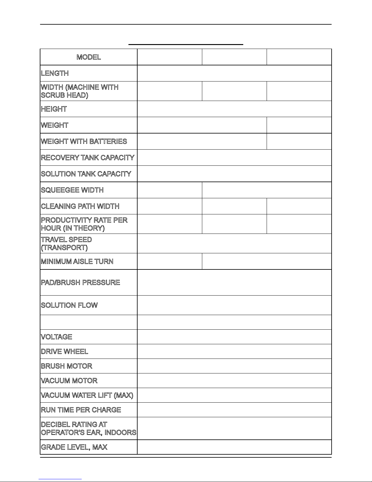
TECHNICAL SPECIFICATIONS
MODEL RS26 RS28 RS32
LENGTH 61.6 in / 1,565 mm
WIDTH (MACHINE WITH
SCRUB HEAD)
32 in / 815 mm 33.7 in / 855 mm 37.4 in / 950 mm
HEIGHT 56.7 in / 1,440 mm
WEIGHT 618 lbs / 280 Kg 640 lbs / 290 Kg
WEIGHT WITH BATTERIES 880 lbs / 400 Kg 900 lbs / 410 Kg
RECOVERY TANK CAPACITY 29 Gal / 110 L
SOLUTION TANK CAPACITY 29 Gal / 110 L
SQUEEGEE WIDTH 33.8 in / 860 mm 40 in / 1,030 mm
CLEANING PATH WIDTH 26 in / 650 mm 28 in / 710 mm 32 in / 810 mm
PRODUCTIVITY RATE PER
HOUR (IN THEORY)
46, 300 ft
2
4,300 m
2
49, 500 ft
2
4,600 m
2
55, 600 ft
2
5,200 m
2
TRAVEL SPEED
(TRANSPORT)
4 Mile / h
6.5 Km / h
MINIMUM AISLE TURN 71 in / 1,800 mm 75 in / 1,900 mm
PAD/BRUSH PRESSURE
80 lbs / 35 Kg
120 lbs / 55 Kg
160 lbs / 75 Kg
SOLUTION FLOW
0 ~ 0.7 Gal / Min
0 ~ 2.7 L / Min
BATTERIES 4 x 6V, 240AH@20Hr
VOLTAGE 24V DC
DRIVE WHEEL 1.1 hp / 0.8 KW
BRUSH MOTOR (2) 0.6 hp / 0.45 KW, 210 RPM
VACUUM MOTOR 0.6 hp / 0.45KW
VACUUM WATER LIFT (MAX) 70 in. H2O / 1780 mm. H2O
RUN TIME PER CHARGE 3~3.5 Hours
DECIBEL RATING AT
OPERATOR'S EAR, INDOORS
68 dB(A)
GRADE LEVEL, MAX Scrubbing: 4°/7% Transporting (empty):10°/17.5%
Page 14

14
ICE RS26 / RS28 / RS32
PARTS LIST
MAIN FRAME GROUP
Page 15

15
ICE RS26 / RS28 / RS32
PARTS LIST
MAIN FRAME GROUP
DIA
NO.
PART
NUMBER
DESCRIPTION
NO
REQ'D
1 8310102 MAIN FRAME, WELDED 1
2 8310133 RUBBER GROMMET 5
3
8310930A PERISTALTIC PUMP, KIT 1
8310931 TUBING, PUMP 1
4 1421409 FLAT WASHER, M4×∮9×0.8 2
5 1422411 LOCK WASHER M4 2
6 1221412 SCREW, PAN HEAD, M4×12 2
7
8310119 10" WHEEL, PU TIRE 2
1612605 BALL BEARING,6205-2RS 4
8 1436025 RETAINING RING, 25MM 2
9 8310150 WHEEL CAP 2
10 6210131 NYLON, CLAMP 5
11 1421510 FLAT WASHER, M5×∮10×1.0 5
12 1221512 SCREW, PAN HEAD, M5×12 5
13 8310120 BRACKET, STAND 2
14 1421824 FLAT WASHER, M8×∮24×2.0 3
15 1422821 LOCK WASHER M8 3
16 1021825 BOLT, HEX, M8×25 3
17 8210118 STATIC STRAP 1
18 8310708A HORN, 24VDC, KIT 1
19 1421307 PLAT WASHER, M3×∮7×0.5 4
20 1211316 SCREW, PAN HEAD, M3×16 2
Page 16

16
ICE RS26 / RS28 / RS32
PARTS LIST
STEERING & DRIVE WHEEL GROUP
Page 17

17
ICE RS26 / RS28 / RS32
PARTS LIST
STEERING & DRIVE WHEEL GROUP
DIA
NO.
PART
NUMBER
DESCRIPTION
NO
REQ'D
1 1113014 LOCK NUT, M14 1
2 1421428 FLAT WASHER, M14×∮28×2.0 1
3
8310602 STEERING WHEEL 1
8310699A CUSHION WITH ICE LOGO 1
4 8310608 BELLOWS, SHAFT, STEERING 1
5 1021825 BOLT, HEX HEAD, M8×25 8
6 1422821 LOCK WASHER, M8 6
7 1421816 FLAT WASHER, M18×∮16×1.6 4
8 8310609 BEARING, FLANGE 2
9 8310605 SHAFT, STEERING WHEEL 1
10 1654025 KEY, 4.75×4.75×25.4 2
11 8310604 U-JOINT 1
12 1534508 SET SCREW, M5 ×8 4
13 1123507 LOCK NUT, M5 3
14 1421510 FLAT WASHER, M5×∮10×1.0 3
15 6210131 CLAMP, NYLON 3
16 8310645 BRACKET, FLANGE BEARING 1
17 1021060 BOLT, HEX HEAD, M10×60 4
18 1422026 LOCK WASHER, M10 4
19 1421030 FLAT WASHER, M10×∮30×2.5 4
20 8310601 SUPPORT BRACKET, STEERING 1
21 1021820 BOLT, HEX HEAD, M8×20 4
22 1421824 FLAT WASHER, M14×∮24×2.0 8
23 8310640 ACCELERATOR/ BRAKE PEDAL 1
24 8310431 HALL SENSOR WITH CABLE 1
25 8310603 STEER-CONTROL ASSY. 1
26 8310650 DRIVE WHEEL, 24VDC 800W 1
27 8310611 PU TIRE, DRIVER WHEEL 1
28 8310612 ARMATURE BRUSH 4
29 8310613 BRUSHES CONNECTION BOX 2
30 8310618A ELECTRICALLY RELEASED BRAKE 1
Page 18

18
ICE RS26 / RS28 / RS32
PARTS LIST
SOLUTION TANK GROUP
Page 19

19
ICE RS26 / RS28 / RS32
PARTS LIST
SOLUTION TANK GROUP
DIA
NO.
PART
NUMBER
DESCRIPTION
NO
REQ'D
1 8310101 SOLUTION TANK 1
2 1221512 SCREW, PAN HEAD, M5×12 2
3 1421510 FLAT WASHER, M5×∮10×1.0 2
4 8113009 CLAMP, NYLON 2
5 1021820 BOLT, HEX HEAD, M8×20 12
6 1421824 FLAT WASHER, M8×∮24×2.0 13
7 8310139 PLATE 2
8 8310151A NON-SLIP MAT 2
9 8310132 FOOTREST PLATE 1
10 1222508 SCREW, M5×8 4
11 1512820 SCREW, HEX SOCKET, M8×20 2
12 1421816 FLAT WASHER, M8×∮16×1.6 2
13 8310140 JUNCTION PLATE 2
14 1422821 LOCK WASHER, M8 8
15 8310130 BRACKET, SOLUTION TANK MNTG 3
16 8310124 ELBOW, G1/2 1
17 8310142 NUT, M36 1
18 8310141 SEALING 2
19 8310238A SENSOR, SOLUTION LEVEL, KIT 1
20 8310125 CAP, SOLUTION TANK 1
21 1021825 BOLT, HEX HEAD, M8×25 1
22 8310225 SLEEVE, ∮8.1×∮12.7×7.8 1
23 8310224 ARM, RECOVERY TANK SUPPORT 1
24 1962050 CLAMP, 2 INCH 1
25 8011030 HOSE ASSEMBLY 1
26 8310123 ADAPTER, STRAINER ASSY 1
27 8310122 STRAINER ASSY 1
Page 20

20
ICE RS26 / RS28 / RS32
PARTS LIST
RECOVERY TANK GROUP
Page 21

21
ICE RS26 / RS28 / RS32
PARTS LIST
RECOVERY TANK GROUP
DIA
NO.
PART
NUMBER
DESCRIPTION
NO
REQ'D
1 8310238A SENSOR, SOLUTION LEVEL, KIT 1
2 8310201 RECOVERY TANK 1
3 8310237 FILTER, DUST 1
4 1021820 BOLT, HEX HEAD, M8×20 21
5 1421824 FLAT WASHER, M8×∮24×2.0 25
6 8310227 HINGE, WELDED 2
7 1513820 SCREW, HEX SOCKET, M8×20 2
8 8310226 HINGE, LEAF 2
9 8310250 DEBRIS COLLECTOR 1
10 8012008 BUSHING 2
11 1421618 FLAT WASHER, M6×∮18×1.6 2
12 1321413 SELF-TAPPING, ST4.8 x 13 2
13 1221516 SCREW, PAN HEAD, M5×16 8
14 1421510 FLAT WASHER, M5×∮10×1.0 12
15 2310129 CLAMP, HOSE 2
16 6210111 CLAMP, HOSE 2
17 8011030 DRAIN HOSE 1
18 1962050 CLAMP, 2 INCH 1
19 4010316 ICE LOGO 2
20 8310126 HINGE ASSY. 2
21 8113009 CLAMP, NYLON 4
22 1221512 SCREW, PAN HEAD, M5×12 4
23 8310221 SPACER 2
24 8310220 COMPRESSION SPRING 2
25 8310222 FLAT WASHER, LARGE 4
26 8310216 COVER, SOLUTION TANK 1
27 8310219 SEALING STRIP 1
28 1022860 BOLT, HEX HEAD, M8×60 2
29 1123810 LOCK NUT, M8 1
30 1021825 BOLT, HEX HEAD, M8×25 1
31 8310225 SLEEVE, ∮8.1×∮12.7×7.8 2
32 8310223 ARM, RECOVERY TANK SUPPORT 1
33 8310215 BRACKET, RECOVERY TANK SUPPORT 1
34 8310211 BRACKET, SUPPORT 1
35 8310214 SPACER, RUBBER 1
Page 22

22
ICE RS26 / RS28 / RS32
PARTS LIST
RECOVERY TANK COVER GROUP
Page 23

23
ICE RS26 / RS28 / RS32
PARTS LIST
RECOVERY TANK COVER GROUP
DIA
NO.
PART
NUMBER
DESCRIPTION
NO
REQ'D
1 1221512 SCREW, PAN HEAD, M5×12 5
2 1421510 FLAT WASHER, M5×∮10×1.0 9
3 8310138A CAUTION LIGHT, KIT 1
4 1123507 LOCK NUT, M5 2
5 8310241 PLATE, CATUION LIGHT 1
6 8310202 RECOVERY TANK COVER 1
7
8310260 AMETK VACUUM MOTOR, 3 STAGE, KIT 1
8132006 CARBON BRUSH FOR VACUUM MOTOR 2
8 8310207 VACUUM HOSE 1
9 1962050 CLAMP, 2 INCH 2
10 1123608 LOCK NUT, M6 8
11 1421612 FLAT WASHER, M6×∮12×1.6 4
12 8310204 ADAPTER, VACUUM HOSE 1
13 8310205 GASKET, ADAPTER 1
14 8310230 GASKET, DUST FILTER 1
15 1021620 BOLT, HEX HEAD, M6×20 4
16 8310232 BRACKET 1
17 1421618 FLAT WASHER, M6×∮18×1.6 12
18 1022600 BOLT, HEX HEAD, M6×100 1
19 8310228 SUPPORT, RECOVERY TANK COVER 1
20 8310231 SLEEVE, ∮6.4×∮9.5×4 1
21 1021616 BOLT, HEX HEAD, M6×16 1
22 8310236 SPACER, NYLON 1
23 8310235 SLEEVE, ∮6.4×∮9.5×8 1
24 8310229 SEALING STRIP 1
25 1021610 BOLT, HEX HEAD, M6×10 2
26 1422616 LOCK WASHER, M6 3
27 1021820 BOLT, HEX HEAD, M8×20 4
28 1421824 FLAT WASHER, M8×∮24×2.0 4
29 8310203 PLATE, VACCUM MOTOR MNTG 1
30 8310208 ISOLATER, M6 3
31 8310209 BRACKET, VACCUM MOTOR 1
32 8310234 INSULATION 1
33 1311316 SCREW, SELF-TAPPING, ST4.8×16 4
34 8310206 SEAL, FAN 1
Page 24

24
ICE RS26 / RS28 / RS32
PARTS LIST
CONTROL PANEL GROUP
Page 25

25
ICE RS26 / RS28 / RS32
PARTS LIST
CONTROL PANEL GROUP
DIA
NO.
PART
NUMBER
DESCRIPTION
NO
REQ'D
1 1221512 SCREW, PAN HEAD, M5×12 8
2 1421510 FLAT WASHER, M5×∮10×1.0 11
3 8311703 DECAL, CONTROL PANEL 1
4 8311702 PLATE, CONTROL PANEL 1
5 8310712 GASKET, CONTROL PANEL 1
6
8310773 PCB, CONTROL PANEL (AGM / EN) 1
8310775 PCB, CONTROL PANEL (WET FLOODED / EN) 1
7 1221306 SCREW, PAN HEAD, M3×6 5
8 8310701 CONROL HOUSING 1
9 1421824 FLAT WASHER, M8×∮24×2.0 4
10 1422821 LOCK WASHER, M8 4
11 1021825 BOLT, HEX HEAD, M8×25 4
12 1321110 SCREW, SELF-TAPPING, ST3.5×10 3
13 1421409 FLAT WASHER, M4×∮9×0.8 3
14 8133610 LED LIGHT, KIT 1
15 8133601 BASE, LED LIGHT 1
16 1221520 SCREW, PAN HEAD, M5×20 3
17 8133602 COVER, LED LIGHT 1
18 4010316 ICE LOGO 1
19 8310711 GASKET, SWITCH PANEL 1
20 8310702 PLATE, SWITCH PANEL 1
21
8310704 DECAL, SWITCH PANEL, RS32 1
8312704 DECAL, SWITCH PANEL, RS28 1
8310750 DECAL, SWITCH PANEL, RS26 1
22 2010121 ICE LOGO, SMALL 1
23 8310709 ROCKER SWITCH 2
24 8310707 EMERGENCY STOP SWITCH 1
25 8310706A KEY SWITCH, KIT 1
Page 26

26
ICE RS26 / RS28 / RS32
PARTS LIST
MAIN CONTROLLER GROUP
Page 27

27
ICE RS26 / RS28 / RS32
PARTS LIST
CONTROLLER GROUP
DIA
NO.
PART
NUMBER
DESCRIPTION
NO
REQ'D
1 1021616 SCREW, HEX HEAD, M6×16 12
2 1422616 LOCK WASHER, M6 18
3 1421618 FLAT WASHER, M6×∮18×1.6 15
4 8310480 FUSE, 150A 1
5 8114705 INSULATOR 3
6 8310422 BRACKET, INSULATOR 2
7 8310133 RUBBER GROMMET 2
8 8310740 CIRCUIT BREAKER, 5A 1
9 8014068 CIRCUIT BREAKER, 10A 1
10 8310450 BRACKET, SCRUB HEAD LIFTING 1
11 1211330 SCREW, PAN HEAD, M3×30 2
12 8310425 BRACKET 2
13 1021825 BOLT, HEX HEAD, M8×25 5
14 1422821 LOCK WASHER, M8 5
15 1421828 FLAT WASHER, M8×∮28×2.5 5
16 1123305 LOCK NUT, M3 4
17 1434300 WASHER, TOOTH, M3 4
18 8310423 MICRO SWITCH 1
19 1421307 FLAT WASHER, M3×∮7×0.5 2
20 1211320 SCREW, PAN HEAD, M3×20 2
21 8310763 OFF BOARD CHARGER SOCKET 1
22 8112030 POWER CORD, BATTERY CHARGER, US 1
23 1123507 LOCK NUT, M5 4
24 8210106A ON BOARD BATTERY CHARGER, 25A 1
25 1121505 HEX NUT, M5 4
26 8310452 BRACKET, BATTERY CHARGER 1
27 1421510 FLAT WASHER, M5×∮10×1.0 6
28 1221520 SCREW, HEX HEAD, M5×20 4
29 8310790 MAIN CONTROLLER 1
30 1423612 FLAT WASHER M6×∮12×1, COPPER 10
31 1023612 HEX BOLT M6 X 12, COPPER 10
32 1422513 LOCK WASHER,M5 2
33 1221525 SCREW, HEX HEAD, M5×25 2
Page 28

28
ICE RS26 / RS28 / RS32
PARTS LIST
SEAT & DETERGENT SYSTEM GROUP
Page 29

29
ICE RS26 / RS28 / RS32
PARTS LIST
SEAT & DETERGENT SYSTEM GROUP
DIA
NO.
PART
NUMBER
DESCRIPTION
NO
REQ'D
1 1221412 SCREW, HEX HEAD, M4×12 4
2 8133502 CLAMP 4
3 8133501 CARGO NET 1
4 1123810 LOCK NUT, M8 5
5 8310413 SUPPORT, SEAT 1
6 8117007 NYLON SPACER 1
7 8310415 TORSION SPRING 1
8 8310414 SLEEVE, ∮8.2×∮11×15 1
9 1421816 FLAT WASHER, M8×∮16×1.6 2
10 1021830 BOLT, HEX HEAD, M8×30 1
11 8310411 PLATE, SEAT MNTG 1
12 8310133 RUBBER GROMMET 1
13 1512820 SCREW, HEX SOCKET, M8×20 4
14 8310402K SEAT, KIT 1
15 1021616 SCREW, HEX HEAD, M6×16 4
16 1421618 FLAT WASHER, M6×
∮
18×1.6 4
17 8310418 CUP HOLDER 1
18 8310419 BRACKET, CUP HOLDER 1
19 1123608 LOCK NUT, M6 2
20 8310460 SPACER 1
21 8310463 ADAPTOR, KEY 1
22 8310464 INSERT, LOCK 1
23 8310461 BOTTLE, DETERGENT 1
24 8310462 CAP, BOTTLE 1
25 1021820 BOLT, HEX HEAD, M8×20 2
26 1422821 LOCK WASHER, M8 2
27 1421828 FLAT WASHER, M8×∮28×2.5 5
28 8310465 BOX, DETERGENT BOTTLE 1
29 8310421 BRACKET 1
Page 30

30
ICE RS26 / RS28 / RS32
PARTS LIST
BATTERY GROUP
Page 31

31
ICE RS26 / RS28 / RS32
PARTS LIST
BATTERY GROUP
DIA
NO.
PART
NUMBER
DESCRIPTION
NO
REQ'D
1 8310401 BOX, BATTERY 1
2 1021820 BOLT, HEX HEAD, M8×20 8
3 1422821 LOCK WASHER, M8 4
4 1421824 FLAT WASHER, M8×∮24×2.0 8
5 8310131 SUPPORT, BATTERY, REAR 1
6 8210105 BATTERY, 6V 230AH 4
7 8310135 TRAY, BATTERY 1
8 8310407 PLATE 2
9 8310136 SUPPORT, BATTERY, FRONT 1
10 8310736 BATTERY CONNECT CABLE, RED 1
11 8310737 BATTERY CONNECT CABLE, RED 1
12 8310733 BATTERY CONNECT CABLE, BLACK 1
13 8114751 JACKET, BATTERY TERMINAL,BLACK 8
14 8210141 BATTERY CONNECT CABLE, BLACK 3
15 1221412 SCREW, PAN HEAD, M4×12 4
16 8310406 COVER 1
17 8210114 COVER 1
18 1662316 RIVET, 3.2×16 4
19 8310404 HINGE ASSEMBLY 1
20 1421409 FLAT WASHER, M4×∮9×0.8 4
21 8310403 COVER 1
Page 32

32
ICE RS26 / RS28 / RS32
PARTS LIST
SCRUB HEAD LIFTING GROUP
Page 33

33
ICE RS26 / RS28 / RS32
PARTS LIST
SCRUB HEAD LIFTING GROUP
DIA
NO.
PART
NUMBER
DESCRIPTION
NO
REQ'D
1 8310320 PIN, COTTER 1
2 8210301 PIN, ∮9.5×38 1
3 8310311 PIN, ∮16×150 1
4 8310312 PIN, ∮16×57 4
5 8210309 PIN, COTTER 6
6 8310303A LINEAR ACTUATOR, KIT 1
7 8310305 PLATE, ARM, SCRUB HEAD LIFTING 2
8 8310314 FLAT WASHER, LARGE 2
9 8310313 PIN, ∮12×90 1
10 1032090 BOLT, HEX HEAD, M10×90 1
11 1421030 FLAT WASHER, M10×∮30×2.5 4
12 8310304 BRACKET, SCRUB HEAD LIFTING 1
13 1421020 FLAT WASHER, M10×∮20×2 2
14 8310307 BUSHING, FLANGE 2
15 1123012 LOCK NUT, M10 3
16 8310144 SLEEVE, ∮16×∮18.6×25.4 4
17 8310118 ARM, SCRUB HEAD LIFTING 2
18 1011025 BOLT, HEX HEAD, M10×25 4
19 8310306 SLEEVE, ∮10.5×∮18.5×34 2
20 8310308 SPRING 1
Page 34

34
ICE RS26 / RS28 / RS32
PARTS LIST
SCRUB HEAD GROUP
Page 35

35
ICE RS26 / RS28 / RS32
PARTS LIST
SCRUB HEAD GROUP
DIA
NO.
PART
NUMBER
DESCRIPTION
NO
REQ'D
1
8310399 BRUSH MOTOR, 24VDC 450W, KIT 2
8310316 CARBON BRUSH 4
2 1655025 KEY, 5×5×25 2
3
8311301 SCRUB HEAD HOUSING, RS26 1
8312301 SCRUB HEAD HOUSING, RS28 1
8310301 SCRUB HEAD HOUSING, RS32 1
4 1021830 BOLT, HEX HEAD, M8×30 9
5 1421824 FLAT WASHER, M8×∮24×2.0 18
6 8310356 BRACKET, LEFT 1
7 8210532 KNOB, M10 4
8 1123810 LOCK NUT, M8 9
9 8210531 KNOB, M6 10
10 8310355 CLAMP, SIDE SKIRT 2
11
8310365 BLADE, SIDE SKIRT, LINATEX 2
8310366 BLADE, SIDE SKIRT, PU (OPTION) 2
12 8310357 BRACKET, SIDE SKIRT, LEFT 1
13 1421020 FLAT WASHER, M10×∮20×2.0 6
14 1422010 LOCK NUT, 3/8 6
15 1023010 BOLT, HEX HEAD, 3/8-16×1 6
16 8210804 SPACER 4
17 8210805 HUB, BRUSH DRIVE 2
18 1421828 FLAT WASHER, M8×∮28×3.0 2
19 1422821 LOCK WASHER, M8 2
20 9000004 CLUTCH, G-400S 2
21
9050013 BRUSH, 13 INCH, RS26 2
9050014 BRUSH, 14 INCH, RS28 2
9050016 BRUSH, 16 INCH, RS32 2
22 9000003 CENTER LOCK, #3 2
23
9040013 PAD DRIVER, 13 INCH, RS26 2
9040014 PAD DRIVER, 14 INCH, RS28 2
9040016 PAD DRIVER, 16 INCH, RS32 2
24
8311358 SKIRT, RS26 1
8312358 SKIRT, RS28 1
8310358 SKIRT, RS32 1
25
8311359 CLAMP, SKIRT, RS26 1
8312359 CLAMP, SKIRT, RS28 1
8310359 CLAMP, SKIRT, RS32 1
26 1421618 FLAT WASHER, M6×∮18×1.6 7
27 1021616 BOLT, HEX HEAD, M6×16 7
28 8310361 BRACKET, PROTECTIVE WHEEL 1
29 1021840 BOLT, HEX HEAD, M8×40 1
30 8310362 PROTECTIVE WHEEL 1
31 8115404 SLEEVE, ∮8×∮12.7×12.7 6
32 1022800 BOLT, HEX HEAD, M8×100 1
33 8310354 KNOB, M10 4
34 8310351 BRACKET, SIDE SKIRT, RIGHT 1
35 8310353 BRACKET, RIGHT 1
Page 36

36
ICE RS26 / RS28 / RS32
PARTS LIST
SQUEEGEE GROUP / 水刮组件
Page 37

37
ICE RS26 / RS28 / RS32
PARTS LIST
SQUEEGEE GROUP / 水刮组件
DIA
NO.
PART
NUMBER
DESCRIPTION
NO
REQ'D
1 8310506 PIN, ∮10×45 2
2 8310590A LINEAR, ACTUATOR, KIT 1
3 8310320 PIN, COTTER 2
4 1121008 HEX NUT, M10 2
5 8310503 BRACKET, SQUEEGEE 1
6 8310240 VACUUM HOSE 1
7 1123115 LOCK NUT, M12 1
8 8310550 CASTER, 2 INCH 2
9 8310501 COMPRESSION SPRING, 1
10 8310504 ARM, SQGE LIFTING 1
11 8310505 FLEX BUSHING, TPU 2
12 8210525 SHORT CLAMP ASSEMBLY 1
13 1221575 SCREW, PAN HEAD, M5×75 1
14 8118624 SHAFT
1
15 8118623 SPACER
1
16 1123507 LOCK NUT, M5 1
17
8311514 CLAMP ASSEMBLY, RS26 1
8310514 CLAMP ASSEMBLY, RS28 / RS32 1
18
8311531 REAR BLADE, LINATEX, RS26 1
8310531 REAR BLADE, LINATEX, RS28 / RS32 1
8311541 REAR BLADE, PU, RS26, OPTION 1
8310541 REAR BLADE, PU, RS28 / RS32, OPTION 1
19
8311561 SQUEEGEE HOSING, RS26 1
8310561 SQUEEGEE HOSING, RS28 / RS32 1
20
8311562 RETAINER, SQUEEGEE, RS26 1
8310562 RETAINER, SQUEEGEE, RS28 / RS32 1
21
8311560 SQUEEGEE ASSEMBLY, RS26 1
8310560 SQUEEGEE ASSEMBLY, RS28 / RS32 1
22
8311534 FRONT BLADE, LINATEX, RS26 1
8310534 FRONT BLADE, LINATEX, RS28 / RS32 1
8311544 FRONT BLADE, PU, RS26, OPTION 1
8310544 FRONT BLADE, PU, RS28/ RS32, OPTION 1
23 1021835 BOLT, HEX HEAD, M8×35 2
24 8210518 KNOB, M8 4
25 8115404 SLEEVE, ∮8×∮12.7×12.7 2
26 8116009 PROTECTIVE WHEEL 2
27 1421824 FLAT WASHER, M8×∮24×2 4
28 1123810 LOCK NUT, M8 2
29 8210309 PIN, COTTER 2
30 8310311 PIN, ∮16×150 1
31 8310508 PIN, ∮12×100 1
32 8310509 EXTENSION SPRING 2
33 1031212 BOLT, HEX HEAD, M12×120 1
34 1421030 FLAT WASHER, M10×∮30×2.5 1
35 1021060 BOLT, HEX HEAD, M10×60 1
36 8310507 ADAPTER 1
Page 38

38
ICE RS26 / RS28 / RS32
PARTS LIST
SOLUTION & DETERGENT SYSTEM
Page 39

39
ICE RS26 / RS28 / RS32
PARTS LIST
SOLUTION & DETERGENT SYSTEM
DIA
NO.
PART
NUMBER
DESCRIPTION
NO
REQ'D
1 8310124 ELBOW, G1/2 1
2 1962025 CLAMP 16-25MM 8
3 8310901 TUBING, ID=16MM L=500MM 1
4 8310375 ELBOW, CHEMICAL CONNECTOR 1
5 8310371 SOLENOID VALVE, 24VDC 1
6 1421510 FLAT WASHER, M5×∮10×1.0 2
7 1422513 LOCK WASHER M5 2
8 1221512 SCREW, PAN HEAD, M5×12 2
9 8310902 TUBING, ID=16MM L=40MM 1
10 8310903 TUBING, ID=12MM L=175MM 1
11 8310374 FITTING, PLASTIC 1
12 8310904 TUBING, ID=12MM L=210MM 1
13 8310905 TUBING, ID=4MM L=330MM 3
14 8310930A DETERGENT PUMP, KIT 1
15 1914080 TIE, 3×80MM 19
16 8310910 TUBING, ID=4MM L=100MM 3
17 8310467 FITTING 7
18 8310909 TUBING, ID=4MM L=30MM 4
19 8310466 ONE WAY VALVE 1
Page 40

40
ICE RS26 / RS28 / RS32
WEAR AND TEAR PARTS
WEAR AND TEAR PARTS
DIA
NO.
PART
NUMBER
DESCRIPTION
NO
REQ'D
1 8310119 10" WHEEL, PU TIRE 2
2 8116009 PROTECTIVE WHEEL 2
3 8310362 PROTECTIVE WHEEL 1
4
8311531 REAR BLADE, LINATEX, RS26 1
8310531 REAR BLADE, LINATEX, RS28 / RS32 1
5
8311534 FRONT BLADE, LINATEX, RS26 1
8310534 FRONT BLADE, LINATEX, RS28 / RS32 1
6
9050013 BRUSH, 13 INCH, RS26 2
9050014 BRUSH, 14 INCH, RS28 2
9050016 BRUSH, 16 INCH, RS32 2
7
9040013 PAD DRIVER, 13 INCH, RS26 2
9040014 PAD DRIVER, 14 INCH, RS28 2
9040016 PAD DRIVER, 16 INCH, RS32 2
Page 41

ICE RS26 / RS28 / RS32
41
WIRING DIAGRAM
BAT: 4-6VDC batteries
FU: 150A fuse
CW: Off-board charger interlock switch
BR1: Main controller circuit breaker, 5A
KEY SW: Main power key switch
AS: Alarm lamp switch
LED2: Alarm lamp
CH1: On-board battery charger
CH2: Off-board battery charger port
LED1: Work LED light
BR2: Brake circuit breaker, 10A
M3: Traction motor
M1: Brush motor, left
M6: Brush motor, right
M2: Vacuum motor
AP: Accelerator Pedal, sensor
SL: Solution tank water level sensor
RF: Recovery tank water level sensor
RT: Reverse switch
ST: Seat switch
EG: Emergency stop switch
M4: Scrub head lifting actuator
M5: Squeegee lifting actuator
BK: Brake coil
DP: Detergent pump
EW: Solution solenoid valve
HN: Horn
 Loading...