

Page 1

PegasusHS
Service Manual
P/N 361854-21
Revision: AA, November 2006
Page 2

Copyright 2006, Clearmark solutions LLP. (herein referred to as ICE). All rights reserved.
This document is the property of Clearmark solutions.and contains confidential and
proprietary information owned by ICE Any unauthorized copying, use or disclosure of it
without the prior written permission of ICE is strictly prohibited.
ICE (interactive coding equpiment)
Phone: 01159 640144
Fax: 01159 639317
Olympic House,Willow Drive
Sherwood Park,Nottingham
NG15 0DP
www.interactivecoding.com
Page 3

Rev AA i
Compliance Information
For Customers in U.S.A.
This device complies with Part 15 of the FCC Rules. Operation is
subject to the following two conditions: 1) this device may not cause
harmful interference, and 2) this device must accept any interference
received, including interference that may cause undesired operation.
Warning
Changes or modifications to this unit not expressly approved by
the party responsible for compliance could void the user’s
authority to operate the equipment.
This equipment has been tested and found to comply with the limits
for a Class A digital device, pursuant to Part 15 of the FCC Rules.
These limits are designed to provide responsible protection against
harmful interference when the equipment is operated in a commercial
environment. This equipment generates, uses, and can radiate radio
frequency energy and, if not installed and used in accordance with the
instruction manual, may cause harmful interference to radio
communications. Operation of this equipment in a residential area is
likely to cause harmful interference. In such cases, the users will be
required to correct the interference at their own expense.
Shielded cables must be used with this unit to ensure compliance with
Class A FCC limits.
The user may find the following booklet prepared by the Federal
Communications Commission helpful: How to Identify and Resolve
Radio-TV Interference Problems. This booklet is available from the
U.S. Government Printing Office, Washington, DC 20402, Stock No.
004-00-00345-4. This equipment has been tested and certified for
compliance with U.S. regulations regarding safety and electrical
emissions by TUV Rheinland of North America, Inc.
For Customers in Canada
This digital apparatus does not exceed the Class A limits for radio
noise emissions from digital apparatus set out in the Radio
Interference Regulations of the Canadian Department of
Communications.
This equipment has been tested and certified for compliance with
Canadian regulations regarding safety and electrical emissions by
TUV Rheinland of North America, Inc.
Page 4

ICE Pegasus Service Manual
ii
Rev AA
Pour la Clientèle du Canada
Le present appareil numerique n’emet pas de bruits radioelectriques
depassant les limites applicales aux appareils numerique de las class A
prescrites dans le Reglement sur le brouillage radioelectrique edicte
par le ministere des Communications du Canada.
Cet équipement est certifié CSA.
For Customers in the European Union
This equipment displays the CE mark to indicate conformance to the
following legislation.
• EN55022:1998
• EN55024:1998
• EN61000-6-2:2001
• FCC CFR 47 parts 15.107 and 15.109
Page 5

Rev AA iii
Support and Training
Contact Information
If you have any questions or need assistance, please contact ICE
Technologies Inc. at 01159 640144
Interactive Coding Equipment (ICE)
Olympic House
Willow Drive
Sherwood Park
Nottingham
NG15 0DP
T: 01159 640144
F: 01159 639317
S
ervice Program
About Total Source Commitment
Total Source® TOTAL SERVICE PLUS RELIABILITY, is the
ICE.
commitment to provide you - our customer - the complete service
you deserve.
The Total Source Commitment
The ICE Service Program is an integral p
art of our business in
providing marks, codes, and images where, when, and how often
customers specify for packages, products, or printed materials. Our
commitment includes:
• Applications support
• Installation services
• Maintenance training
• Customer response center
• Technical support
• Field service
• Extended hours phone assistance
• Parts and supplies
•Repair service
Page 6

iv
Rev AA
Customer Training
If you wish to perform your own service and maintenance on
the printer, ICE. highly recommends that you complete a
Customer Training Course on the printer.
Note: The manuals are intended to be supplements to (and not replacements
for) ICE. Customer Training.
For more information on ICE. Customer Training Courses, call 01159
640144.
ICE Pegasus Service Manual
Page 7

Rev AA i
Table of Contents
Compliance Information
For Customers in U.S.A.. . . . . . . . . . . . . . . . . . . . . . . . . . . . . . . . . . . . . . . i
For Customers in Canada . . . . . . . . . . . . . . . . . . . . . . . . . . . . . . . . . . . . . . i
Pour la Clientèle du Canada . . . . . . . . . . . . . . . . . . . . . . . . . . . . . . . . . . . .ii
For Customers in the European Union. . . . . . . . . . . . . . . . . . . . . . . . . . . .ii
Support and Training
Contact Information . . . . . . . . . . . . . . . . . . . . . . . . . . . . . . . . . . . . . . . . . iii
Service Program . . . . . . . . . . . . . . . . . . . . . . . . . . . . . . . . . . . . . . . . . . . . iii
Customer Training . . . . . . . . . . . . . . . . . . . . . . . . . . . . . . . . . . . . . . . . . . iv
Chapter 1 — Safety
Introduction. . . . . . . . . . . . . . . . . . . . . . . . . . . . . . . . . . . . . . . . . . . . . . . . 1–1
Safety Conventions Used in the Manual. . . . . . . . . . . . . . . . . . . . . . . . 1–2
General Warning Notices . . . . . . . . . . . . . . . . . . . . . . . . . . . . . . . . . 1–2
General Caution Notices. . . . . . . . . . . . . . . . . . . . . . . . . . . . . . . . . . 1–3
Safety Guidelines . . . . . . . . . . . . . . . . . . . . . . . . . . . . . . . . . . . . . . . . . . . 1–4
Comply with Electrical Codes . . . . . . . . . . . . . . . . . . . . . . . . . . . . . 1–4
Do Not Remove Warning Labels. . . . . . . . . . . . . . . . . . . . . . . . . . . 1–5
Placement of the Printer . . . . . . . . . . . . . . . . . . . . . . . . . . . . . . . . . . . . . 1–5
Using Printer Accessories. . . . . . . . . . . . . . . . . . . . . . . . . . . . . . . . . 1–5
Chapter 2 — Introduction
Equipment Description . . . . . . . . . . . . . . . . . . . . . . . . . . . . . . . . . . . . . . 2–1
About this Manual . . . . . . . . . . . . . . . . . . . . . . . . . . . . . . . . . . . . . . . . . . 2–2
Related documents . . . . . . . . . . . . . . . . . . . . . . . . . . . . . . . . . . . . . . 2–2
Theory of Printing . . . . . . . . . . . . . . . . . . . . . . . . . . . . . . . . . . . . . . . . . . 2–3
Intermittent Motion Printing . . . . . . . . . . . . . . . . . . . . . . . . . . . . . . 2–3
Continuous Motion Printing . . . . . . . . . . . . . . . . . . . . . . . . . . . . . . 2–4
Chapter 3 — Technical Description
Unpacking the Printer . . . . . . . . . . . . . . . . . . . . . . . . . . . . . . . . . . . . . . . 3–1
Installing the Printer . . . . . . . . . . . . . . . . . . . . . . . . . . . . . . . . . . . . . . . . 3–3
Mounting Considerations . . . . . . . . . . . . . . . . . . . . . . . . . . . . . . . . . . . . 3–3
Printer . . . . . . . . . . . . . . . . . . . . . . . . . . . . . . . . . . . . . . . . . . . . . . . . . 3–3
CLARiTY Controller . . . . . . . . . . . . . . . . . . . . . . . . . . . . . . . . . . . . . 3–5
Air Regulator . . . . . . . . . . . . . . . . . . . . . . . . . . . . . . . . . . . . . . . . . . . 3–7
Encoders . . . . . . . . . . . . . . . . . . . . . . . . . . . . . . . . . . . . . . . . . . . . . . . 3–7
Installing the Ribbon in the Cassette. . . . . . . . . . . . . . . . . . . . . . . . . . . 3–8
Adjusting the Air Pressure . . . . . . . . . . . . . . . . . . . . . . . . . . . . . . . . . . 3–12
Page 8

ii
Rev AA
Working with Printer Connections . . . . . . . . . . . . . . . . . . . . . . . . . . .3–12
Product Sensors/Print Signals . . . . . . . . . . . . . . . . . . . . . . . . . . . .3–12
Encoder . . . . . . . . . . . . . . . . . . . . . . . . . . . . . . . . . . . . . . . . . . . . . . .3–14
Interlocks and Annunciation . . . . . . . . . . . . . . . . . . . . . . . . . . . . .3–15
Data Communication. . . . . . . . . . . . . . . . . . . . . . . . . . . . . . . . . . . .3–16
Cable Connections . . . . . . . . . . . . . . . . . . . . . . . . . . . . . . . . . . . . . .3–16
Switching the Power On . . . . . . . . . . . . . . . . . . . . . . . . . . . . . . . . . . . .3–18
Configuring the Printer . . . . . . . . . . . . . . . . . . . . . . . . . . . . . . . . . . . . .3–19
CLARiTYTM Configuration Manager. . . . . . . . . . . . . . . . . . . . . .3–19
Installing the CLARiTY Configuration Manager . . . . . . . . . . . .3–21
Connecting the CLARiTY Configuration Manager to the Printer3–21
Editing Parameters. . . . . . . . . . . . . . . . . . . . . . . . . . . . . . . . . . . . . .3–23
Saving the Changes in the Printer . . . . . . . . . . . . . . . . . . . . . . . . .3–24
Archiving the Current Parameters. . . . . . . . . . . . . . . . . . . . . . . . .3–24
Loading a Saved Archive . . . . . . . . . . . . . . . . . . . . . . . . . . . . . . . .3–25
Working with the Inputs and Outputs . . . . . . . . . . . . . . . . . . . . . . . .3–25
The Inputs . . . . . . . . . . . . . . . . . . . . . . . . . . . . . . . . . . . . . . . . . . . . .3–25
The Outputs. . . . . . . . . . . . . . . . . . . . . . . . . . . . . . . . . . . . . . . . . . . .3–25
Default Options Configuration. . . . . . . . . . . . . . . . . . . . . . . . . . . . . . .3–26
Chapter 4 — CLARiTY Operating System
Getting started with the CLARiTY. . . . . . . . . . . . . . . . . . . . . . . . . . . . .4–1
Using the Tools Page . . . . . . . . . . . . . . . . . . . . . . . . . . . . . . . . . . . . . . . .4–2
Working with Setup Page . . . . . . . . . . . . . . . . . . . . . . . . . . . . . . . . .4–3
Working with Diagnostics . . . . . . . . . . . . . . . . . . . . . . . . . . . . . . . .4–8
Working with Passwords. . . . . . . . . . . . . . . . . . . . . . . . . . . . . . . . . . . .4–25
Password Protection Set-up . . . . . . . . . . . . . . . . . . . . . . . . . . . . . .4–26
Chapter 5 — Maintenance
Maintaining the Power Supply. . . . . . . . . . . . . . . . . . . . . . . . . . . . . . . .5–2
Replacing the Mains Fuse . . . . . . . . . . . . . . . . . . . . . . . . . . . . . . . . .5–2
Maintaining the CLARiTY Controller . . . . . . . . . . . . . . . . . . . . . . . . . .5–3
Replacing the Power Supply Unit . . . . . . . . . . . . . . . . . . . . . . . . . .5–3
Replacing the CLARiTY Processor PCB and LCD Touchscreen
Assembly . . . . . . . . . . . . . . . . . . . . . . . . . . . . . . . . . . . . . . . . . . . . .5–5
Maintaining the Printer . . . . . . . . . . . . . . . . . . . . . . . . . . . . . . . . . . . . .5–11
Replacing the Compact Flash Card . . . . . . . . . . . . . . . . . . . . . . . .5–11
Replacing the Main PCB . . . . . . . . . . . . . . . . . . . . . . . . . . . . . . . . .5–12
Replacing the Peel Roller. . . . . . . . . . . . . . . . . . . . . . . . . . . . . . . . .5–15
Replacing the Printhead . . . . . . . . . . . . . . . . . . . . . . . . . . . . . . . . .5–17
Setting the Printhead Resistance . . . . . . . . . . . . . . . . . . . . . . . . . .5–18
Maintaining the Cassette. . . . . . . . . . . . . . . . . . . . . . . . . . . . . . . . .5–19
ICE Pegasus Service Manual
Page 9

Rev AA iii
Updating the CLARiTY Operating Software. . . . . . . . . . . . . . . . . . . 5–23
Chapter 6 — System Events
Chapter 7 — Troubleshooting
Chapter 8 — Illustrated Parts List
How to Read the IPL . . . . . . . . . . . . . . . . . . . . . . . . . . . . . . . . . . . . . . . . 8–1
Illustrations. . . . . . . . . . . . . . . . . . . . . . . . . . . . . . . . . . . . . . . . . . . . . 8–1
Alphabets . . . . . . . . . . . . . . . . . . . . . . . . . . . . . . . . . . . . . . . . . . . . . . 8–2
Numbers . . . . . . . . . . . . . . . . . . . . . . . . . . . . . . . . . . . . . . . . . . . . . . . 8–2
Tables. . . . . . . . . . . . . . . . . . . . . . . . . . . . . . . . . . . . . . . . . . . . . . . . . . 8–3
Controller Assembly . . . . . . . . . . . . . . . . . . . . . . . . . . . . . . . . . . . . . . . . 8–4
Printer Assembly . . . . . . . . . . . . . . . . . . . . . . . . . . . . . . . . . . . . . . . . . . . 8–5
Printhead Assembly . . . . . . . . . . . . . . . . . . . . . . . . . . . . . . . . . . . . . 8–5
Cassette Assembly . . . . . . . . . . . . . . . . . . . . . . . . . . . . . . . . . . . . . . . . . . 8–7
Accessories . . . . . . . . . . . . . . . . . . . . . . . . . . . . . . . . . . . . . . . . . . . . . . . . 8–8
Printer Ribbons. . . . . . . . . . . . . . . . . . . . . . . . . . . . . . . . . . . . . . . . . . . . . 8–9
Chapter 9 — Drawings
Printer Dimensions. . . . . . . . . . . . . . . . . . . . . . . . . . . . . . . . . . . . . . . . . . 9–1
Electrical Wiring Schematics. . . . . . . . . . . . . . . . . . . . . . . . . . . . . . . . . . 9–4
ICE Pegasus Service Manual
Page 10
Rev AA Introduction 1-1
1
Safety
This chapter contains the following topics:
• Safety conventions used throug
hout this manual
• Important safety guidelines to follow while operating the equipment
Warning
EQUIPMENT MAINTENANCE. Read this chapter thoroughly
before attempting to install, operate, service, or maintain this
product.
Introduction
The policy of ICE. is to manufacture printing/coding systems and
supplies that meet high standards of performance and reliability.
There
fore, we employ strict quality control measures to eliminate the
potential for defects and hazards in our products.
The intended use of this printer is to print information directly onto the
product. Use of this equipment for any other purposes may lead to serious
personal injury.
The safety guidelines provided in this chapter are intended to educate the
operator on all safety issues, so that the operator can operate the printer
safely.
Page 11
1-2 Safety Conventions Used in the Manual
Rev AA
Safety Conventions Used in the Manual
Specific safety information is listed throughout this manual in the form of
Warning statements. Pay close attention to these statements as they
contain important information that help in avoiding potential hazards to
yourself or to the equipment.
General Warning Notices
The following warnings supplement the specific warnings that appear
elsewhere in the manual. These are general warnings which must be read,
completely understood, and applied by all the personnel involved in the
operation, and/or the maintenance of the machine.
Warning
PERSONAL INJURY. Only trained service or maintenance
personnel should perform these installation procedures. Qualified
personnel have successfully completed the training courses, have
sufficient experience with this printer, and are aware of the potential
hazards to which they may be exposed.
Warning
PERSONAL INJURY. Before attempting any maintenance or repair
on any part of the product, disconnect the printer from the main
power supply and isolate the printer from any external energy
sources including other connected equipment.
Warning
PERSONAL INJURY. Before connecting the compressed air supply
to printer, ensure that the air supply has been isolated. Turn the
regulator adjustment knob counter-clockwise.
Warning
PERSONAL INJURY. The printer uses an operator control console.
Ensure that this panel is mounted at an appropriate working height
and orientation for comfortable operation.
ICE Pegasus Service Manual
Page 12

Rev AA Safety Conventions Used in the Manual 1-3
Warning
PERSONAL INJURY. Keep hands and clothing clear of the printer
while it is on.
Warning
PERSONAL INJURY. To ensure that the connecting cables and pipes
do not become a trip hazard or become entangled in any machinery,
all connecting cables and pipes must be secured safely during
installation.
Warning
ELECTRICAL HAZARD. Voltages used to connect the printer to
other equipment must be limited to no greater than 50 V DC or peak
AC.
Warning
ELECTRICAL HAZARD. Always wear a properly ground wristground strap when handling printed circuit boards. Failure to do so
can result in damage to the board components due to static
electricity.
General Caution Notices
The following caution statements supplement the specific cautions that
appear elsewhere in the manual. These are general cautions, which must
be read, completely understood and applied by all the personnel involved
with the operation, and/or the maintenance of the machine.
ICE Pegasus Service Manual
Page 13

1-4
Safety Guidelines
Rev AA
Caution
EQUIPMENT MAINTENANCE. Before and after performing any
maintenance or repair on the product, check that the two safety
labels are clearly visible. One is on the power supply cover and the
other by the potential nip point next to the pulley in the printer
body.
Caution
EQUIPMENT DAMAGE. The use of incompatible ribbon can
seriously damage your printer and such damage is not covered by
your printer warranty. Use only ribbon approved by your dealer.
Safety Guidelines
This section contains important safety guidelines pertaining to the
operation and handling of the printer and associated equipment.
Warning
SAFETY GUIDELINES. Always observe the following safety
guidelines when operating and handling the printer and associated
equipment.
Comply with Electrical Codes
All the electrical wiring and connections must comply
with applicable local codes. Consult the appropriate
regulatory agency for further information.
ICE Pegasus Service Manual
Page 14
Rev AA Placement of the Printer 1-5
Do Not Remove Warning Labels
Do not, under any circumstances, remove or obstruct any
warning or instruction labels on the printer.
Placement of the Printer
Warning
PERSONAL INJURY. Do not place the printer in a hazardous
location. Hazardous locations might create an explosion, leading to
personal injury.
Hazardous locations, as defined in the United States, are those areas that
may contain hazardous materials in a quantity sufficient to create an
explosion. These are defined in Article 500 of the National Electrical Code
ANSI/NFPA 70–1993.
Outside the United States, you must ensure compliance with all local
regulations regarding equipment placement in potentially hazardous
locations.
Using Printer Accessories
To maintain regulatory approval for the printer, use only Videojet
approved accessories when attaching any device to the equipment.
ICE Pegasus Service Manual
Page 15

Rev AA Equipment Description 2-1
2
Introduction
This chapter contains the following topics:
• A description about the intended use of
the product
• Information about the audience for whom this manual is intended
• A description of how the manual is organized
• Information about other manuals that are associated with this printer
• A description of the theory of printing
Warning
PERSONAL INJURY. Read Chapter 1, “Safety” before attempting to
operate the equipment.
Equipment Description
The Videojet 6210 printer uses high-resolution thermal transfer
technology with a unique electronic ribbon drive system. The printer
offers greater reliability and ease of operation compared to earlier
systems. It can print barcodes, dates, text, and graphics onto flexible
packaging films and labels.
The printer is a suitable replacement for either hot stamp or rotary
printers. It can print in either of the following modes:
• Intermittent Mode (i.e., while the substrate is stationary)
• Continuous Mode (i.e., while the substrate is moving)
It is suitable for use on most horizontal form/fill/seal, vertical form/
fill/seal, and self-adhesive labeling machines.
The product is available in either left-handed or right-handed versions to
suit different configurations of the packaging machine.
Page 16

2-2
About this Manual
Rev AA
About this Manual
This service manual includes information about installing, maintaining,
troubleshooting, and servicing the printer. It also contains sections about
the theory of operation and component identification, including an
illustrated parts breakdown.
This document is intended to be used only by trained service personnel. It
is intended to be a supplement to (and not a replacement for) formal
training. Keep this manual in a safe location where it can be easily
accessed for reference.
Related documents
The Videojet 6210 Operator Manual (P/N 361853) is intended for the
operator and contains information on routine operation of the printer.
Unless specified, all procedures in this manual can be performed by the
operator of the printer. It is mandatory that the personnel read the
Operator Manual before reading the Service Manual.
This manual is a supplement to (and not a replacement for) formal
training.
Warning
PERSONAL INJURY. Customers who intend to service and
maintain the printer themselves must use only qualified personnel
to perform these procedures. Qualified personnel have successfully
completed the training courses, have sufficient experience with this
printer, and are aware of the potential hazards to which they may be
exposed.
ICE Pegasus Service Manual
Page 17
Rev AA Theory of Printing 2-3
Theory of Printing
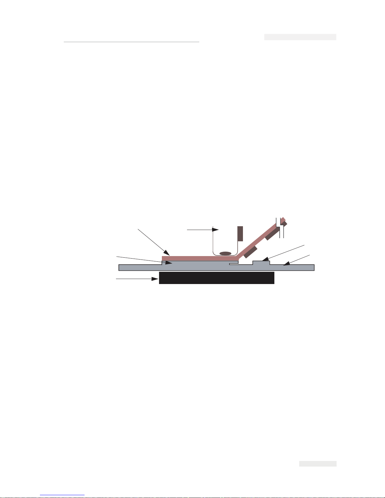
The information on how the thermal transfer printer works is as follows
(Figure 2-1):
• The printhead contains miniature heating
elements under a glass
coat
ing (300 dpi - 12 dots/min)
• A carrier ribbon, with ink bonded to one side is used as
the printing
media
•
The printhead presses against the thermal transfer ribbon with
the ink
side of ribbon
in contact with the substrate, creating an image.
• Print elements heat small areas of the ribbon and this transfers th
e ink
to
the target substrate
• The printhead and the substrate move relative to each other
• T
he print elements are programmable and controlled to create an
image
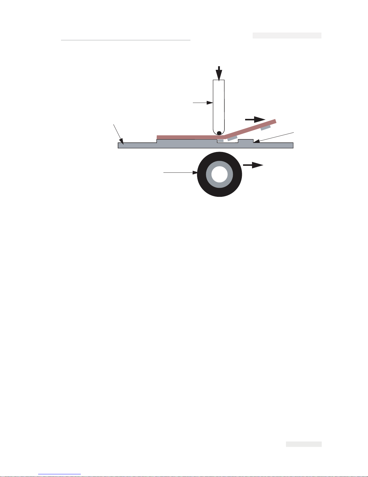
Intermittent Motion Printing
Intermittent motion printing (Figure 2-2 on page 2-4) is the concept used
for printing on stationary packaging films in packaging equipment that
has a start/stop action each time a product is packed. Such applications
can be found in intermittent Vertical Form Fill Seal (VFFS) or bagging
machines, and self adhesive label applicators.
Intermittent motion printing has the following features:
• The substrate is stationary
1
2
3
4
5
6
1. Ribbon Transferred Carbon
2. Substr
ate
3. Platten Rubber
4. In
k
5. B
ase Film
6. T
hermal Printhead
Figure 2-1: Printing Process
ICE Pegasus Service Manual
Page 18
2-4
Theory of Printing
Rev AA
• The printhead traverses across the ribbon, causing print to transfer
onto substrate.
•
The printhead presses against a flat platten pad.
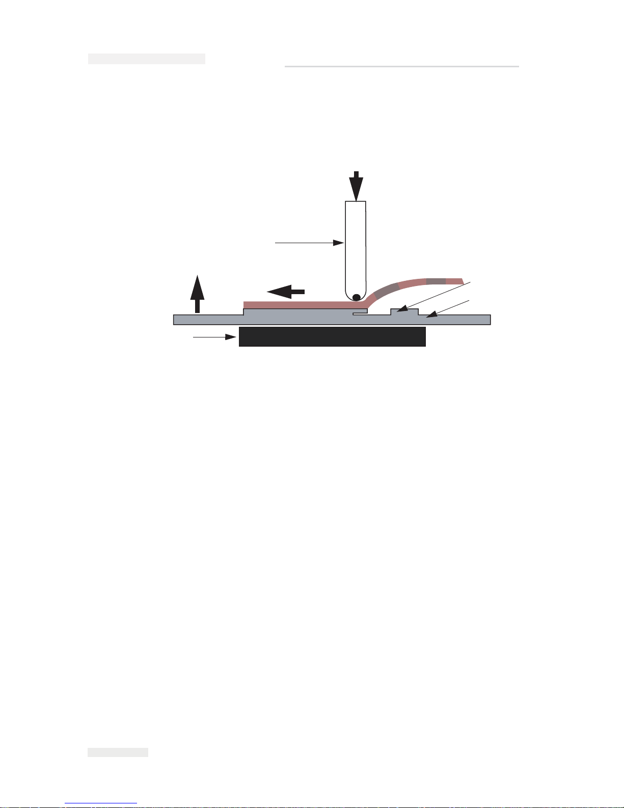
Continuous Motion Printing
Continuous motion printing (Figure 2-3 on page 2-5) is the concept used
for printing on moving packaging films in packaging equipment that has a
continuous moving action each time a product is packed. Such
applications can be found in Continuous Vertical Form Fill Seal (VFFS)
and Horizontal Form Fill Seal (HFFS) or flow-wrap machines.
Continuous motion printing has the following features:
• The substrate moves while the printhead is stationary
• Speed of the substrate is monitored by an encoder
• The ribbon and the substrate speeds are matched by the ribbon drive
• The printhead presses against a rotating print roller
1
2
3
4
1. Ribbon Transferred Carbon
2. Substrate
3. Platten Rubber
4. Th
ermal Printhead
Figure 2-2: Intermittent Printing Motion
HEAD OUT
HEAD IN
PRINT
ICE Pegasus Service Manual
Page 19
Rev AA Theory of Printing 2-5
1
2
3
4
RIBBON FEED
MATERIAL FEED
1. Ribbon Transfer Carbon Print
2. Platt
en Roller
3. Substrate
4. Th
ermal Printhead
Figure 2-3: Continuous Print Motion
ICE Pegasus Service Manual
Page 20

Rev AA Unpacking the Printer 3-1
3
Technical Description
This chapter contains the following topics:
• Unpacking the Printer
• Installing the Printer
• Mounting Considerations
• Installing the Ribbon in the Cassette
• Adjusting the Air Pressure
• Working with Printer Connections
• Switching the Power On
• Understanding Printhead LEDs
•Configuring the Printer
• Working with the Configurable Inputs and Outputs
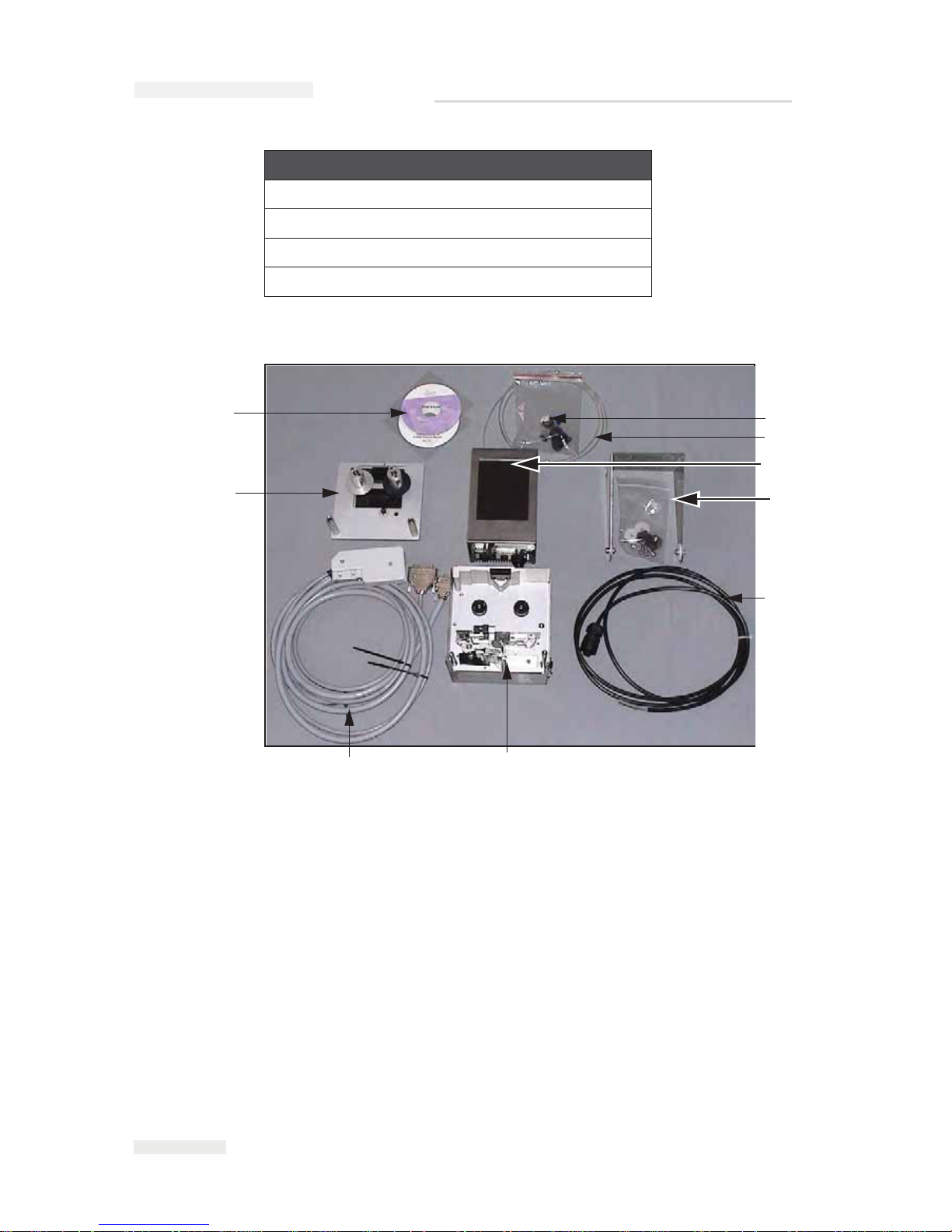
Unpacking the Printer
Inspect the kit for any damage carefully. Refer the list of parts in
Table 3-1 and Figure 3-1 on page 3-2. If any item is damaged or
missing, call ICE., Customer Service Department at 01159 640144.
Printer Part
Printer
Cassette
CLARiTY Controller
Air Regulator
Power Cable
I/O Low Profile Cable Assembly
Table 3-1: Printer Configuration Parts List
Page 21
3-2
Unpacking the Printer
Rev AA
CLARiTY Configuration Manager CD
4mm Air Tubing
CLARiTY Controller Bracket
QA Documentation and CE Certificate
Printer Part
Table 3-1: Printer Configuration Parts List (Continued)
1. Air Regulator
2. 4mm Air Tubing
3. CLARiTY Controller
4.CLARiTY Controller Bracket
5.
Power Co
rd
6. Printer
7.
I/O Low P
rofile Cable
Assembly
8. Cassette
9. CLARiTY Configuration
Manager CD-ROM
Figure 3-1: Printer Configuration Parts
1
2
3
4
5
6
7
8
9
ICE Pegasus Service Manual
Page 22

Rev AA Installing the Printer 3-3
Installing the Printer
Ensure that the following services are available while the printer is being
installed:
• Power: 90 - 264 VAC, 320 VA, 47 - 63 Hz
• Compressed Air: 87 psi (6 bar) max, dry, uncontaminated with a 6 mm
pipe fitting
• Print signal: This is the signal that triggers the printing operation and
can either be a:
- PLC signal
- 24 V DC, PNP registration photocell
- 24 V DC, PNP proximity switch detecting a cam timing point
• An encoder kit (P/N 403358) is required to monitor the speed of the
packaging film on continuous motion packaging machines.
Mounting Considerations
The thermal printhead must act against a flat print platen (in an
intermittent mode) or a print roller (in a continuous mode) in order to
print. The platen or roller is a part of the mounting bracketry.
Printer
The printer can be mounted in any orientation. However, it is important to
ensure that adequate operator access is available to remove and replace
the cassette easily.
The exact position of the printer relative to the packaging machine, needs
to account for:
• The physical constraints of the available space and operator access
• The required position of the print on the substrate
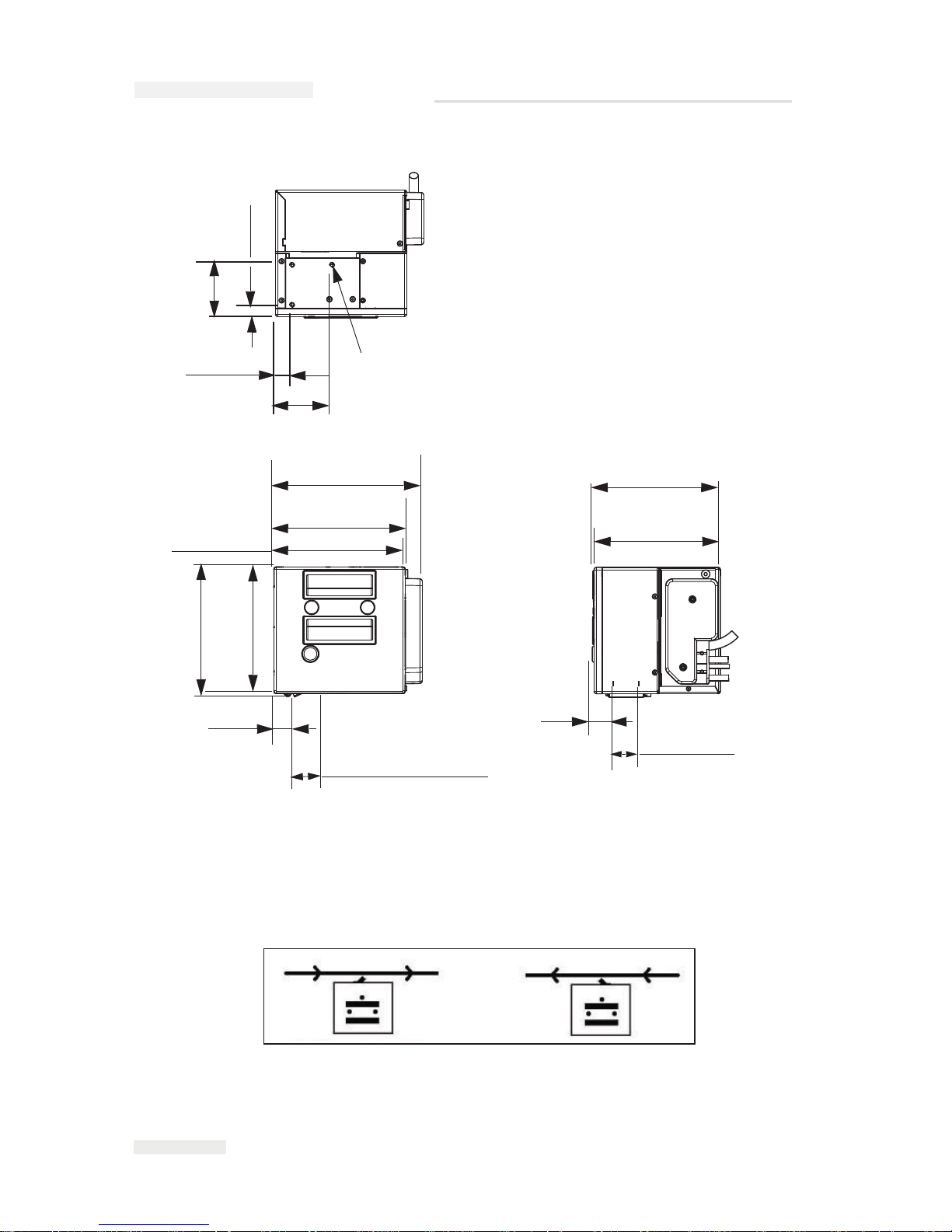
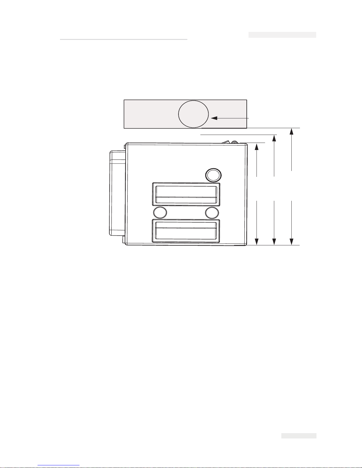
Figure 3-2 on page 3-4 shows the relevant dimensions of the printer
relative to the mounting holes and the printhead. It also shows the
additional space required to give adequate clearance to cables and air
pipes that connect to the unit.
ICE Pegasus Service Manual
Page 23
3-4
Mounting Considerations
Rev AA
Mount the printer using four M6 screws. Consider the direction of travel
of the target material relative to the printer, when you mount the printer
on a continuous motion packaging machine. This determines whether the
printer in use is left-handed or right-handed (Figure 3-3).
64.50 mm (2 PLCS)
14.50 mm
70.73 mm (2.78 inches)
M6 Tapped Holes
Thread Depth 6.00
3 Places
20.73 mm (2 PLCS)
167.15 mm
185.30 mm
158.00 mm
Printhead Retracted
162.50 mm
25.70 mm
32.50 mm (1.28 inches)
157.80 mm
159.60 mm
26.20 mm
32.00 mm
Printable Area
Figure 3-2: Videojet 6210 30 mm RH Printer Dimensions
(7.3 inches)
(6.58 inches)
164.00 mm
(6.46 inches)
(1.01 inches)
Printhead Stroke
(6.4 inches)
(6.22 inches)
(6.23 inches)
(6.21 inches)
(1.03 inches)
(1.26 inches)
(2.54 inches)
0.57 inches
(0.82 inches)
Figure 3-3: Right-handed and Left-handed Printer
Right-handed Printer Left-handed Printer
ICE Pegasus Service Manual
Page 24
Rev AA Mounting Considerations 3-5
The print platen rubber (for printers in intermittent mode) or the roller
(for printers in continuous mode) should be positioned such that it is at a
distance between 6.45 inches and 6.50 inches (164 mm and 165.5 mm) from
the back edge of the printer (Figure 3-4).
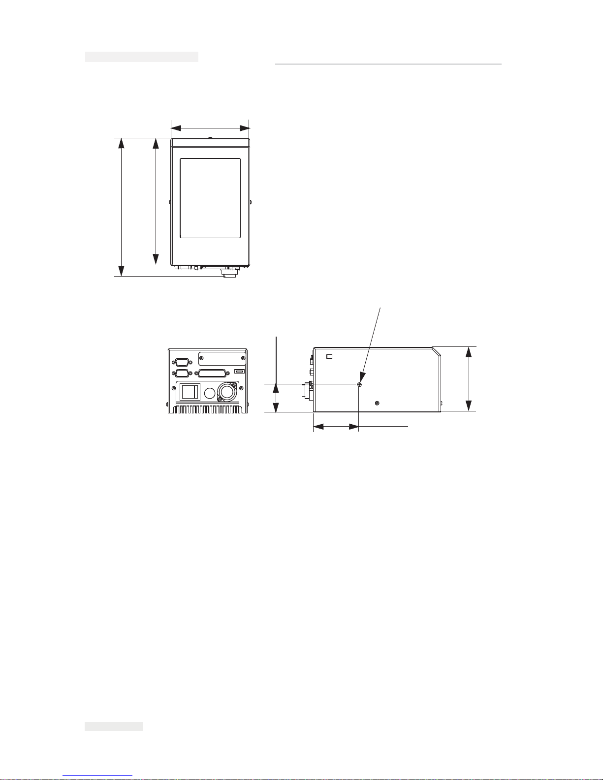
CLARiTY Controller
The CLARiTY operator interface can be mounted at a convenient location
so that the operator has adequate access to the panel. The CLARiTY
controller has a built-in power supply unit.
The unit has two M6 mounting holes located at the sides of the unit, as
shown in Figure 3-5 on page 3-6.
Figure 3-4: Printer Pad or Roller Position
Printer Pad or Roller
158 mm
164 mm
165.5 mm
(6.2 inches)
(6.46 inches)
(6. 52 inches)
ICE Pegasus Service Manual
Page 25
3-6
Mounting Considerations
Rev AA
The maximum distance of the CLARiTY controller from the printer body
is 9.8 ft (3 m).
The CLARiTY controller can be mounted in any convenient location,
provided that the maximum lead length of 9.8 ft (3 m) is not exceeded. The
mounting brackets provided allow you to position the controller against a
convenient vertical flush surface.
Figure 3-5: CLARiTY Controller Dimensions
69.20 mm
208.35 mm
191.25 mm
41.00 mm
M6 Female Thread
Both Sides.
Thread Depth 6.00
96.90 mm
118.90 mm
(4. 68 inches)
(8.2 inches)
(7.53 inches)
(3.81 inches)
(2.72 inches)
(1.61 inches)
ICE Pegasus Service Manual
Page 26

Rev AA Mounting Considerations 3-7
Air Regulator
The air regulator should be connected to a clean, dry factory air supply
using a 6 mm pipe. The 4 mm diameter pipe should be used to connect the
air regulator to the printer.
The air regulator should be mounted close to the printer. The regulator
should be accessible for adjusting and checking the correct pressure of 3
bar.
Encoders
An encoder is used to match the printing speed to the speed of the target
material as it passes the printhead.
Use the Encoder Kit part number 403358 for these applications.
The encoder must ideally be mounted to run on the packaging film, close
to the printer, in order to accurately measure the film speed. Any
discrepancy between measured and actual film speed can result in poor
print quality or ribbon breakage.
Note: Use the encoder only in the continuous mode.
ICE Pegasus Service Manual
Page 27
3-8
Installing the Ribbon in the Cassette
Rev AA
Installing the Ribbon in the Cassette
Caution
EQUIPMENT DAMAGE. The use of incompatible ribbon can
seriously damage your printer and such a damage is not covered by
your printer warranty. Use only the ribbon that is approved by your
dealer.
To install the ribbon, proceed as follows:
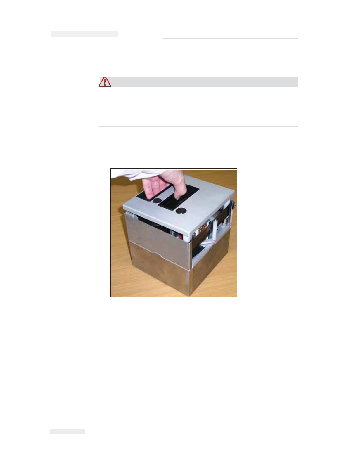
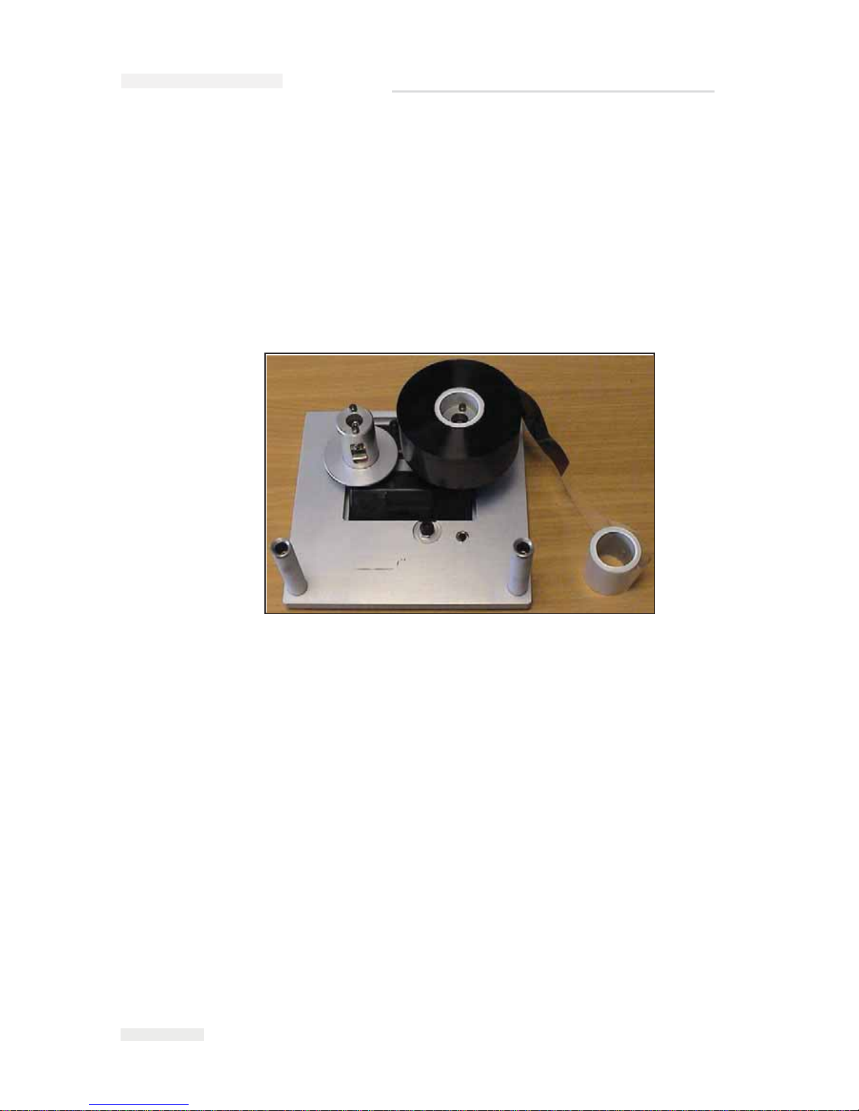
1 Remove the cassette (Figure 3-6).
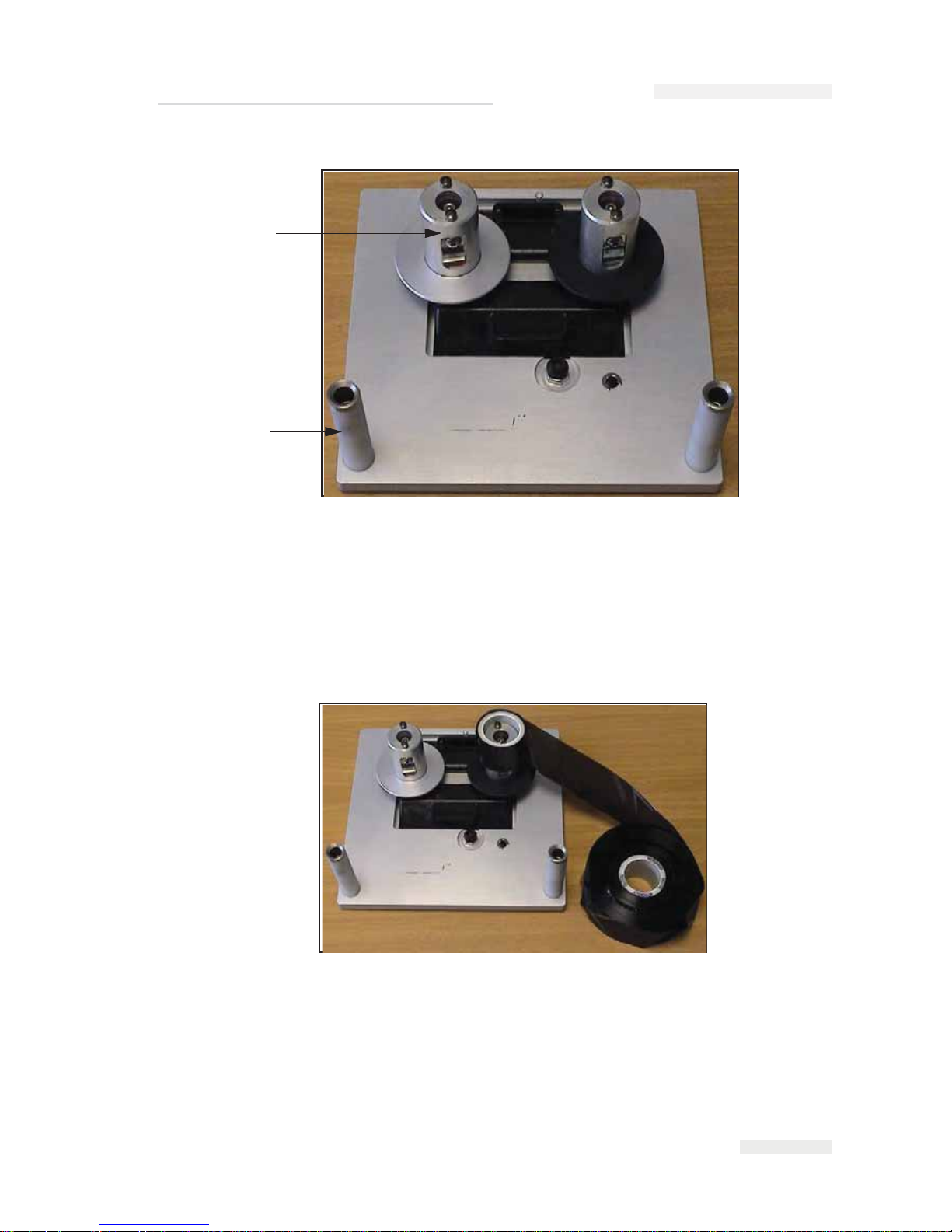
2 Put the cassette down on a flat surface with the ribbon spools (Item 1,
Figure 3-7 on page 3-9) facing upwards and the ribbon rollers (Item 2)
towards you.
Figure 3-6: Cassette Removal
ICE Pegasus Service Manual
Page 28
Rev AA Installing the Ribbon in the Cassette 3-9
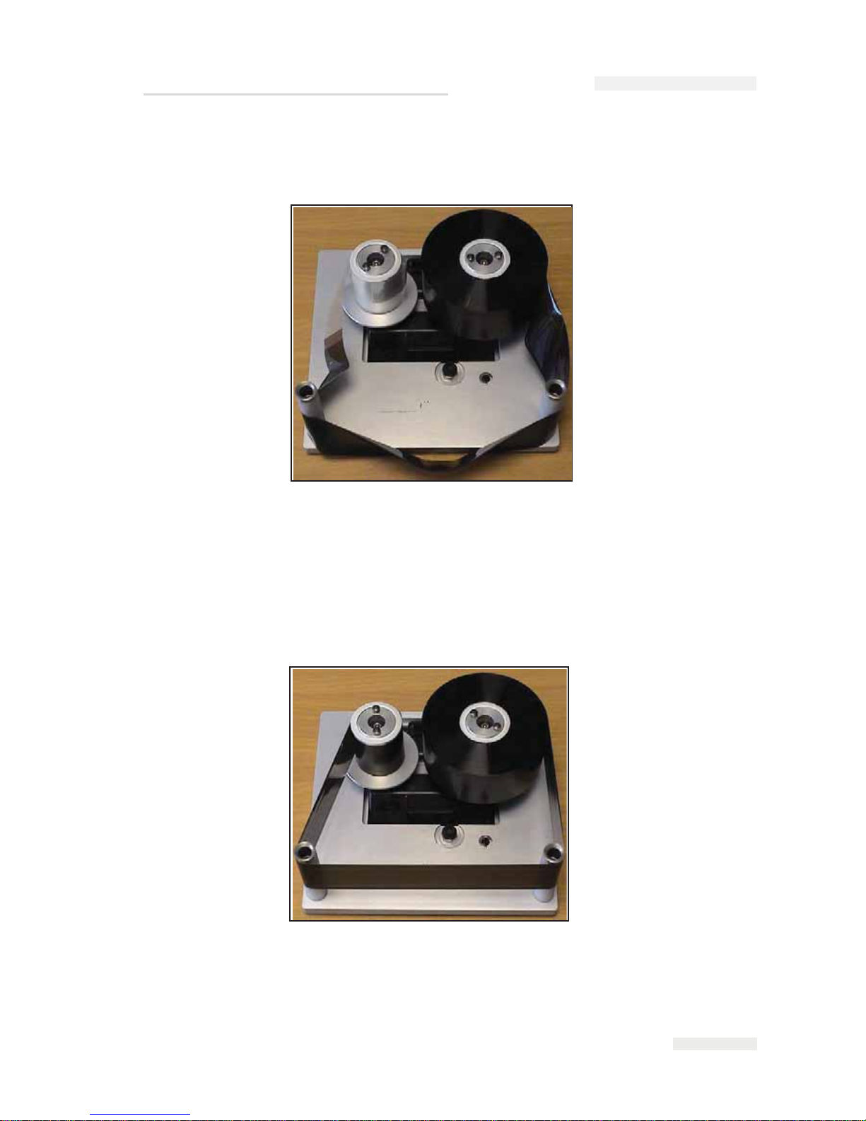
3 Pull the two ribbon spools (one containing the entire used ribbon)
from the cassette firmly, as shown in Figure 3-8. The discs that are
situated under each spool can be used to lever the spool off the
cassette.
4 Discard the used ribbon and the spools.
5 Open a new shrink-wrapped roll of ribbon, and unwind about 12
inches (30 cm) of ribbon.
The spool holders on the cassette have different color discs:
Figure 3-7: Cassette Removed
1. Ribbon Roller (x2)
2.
Ribb
on Spool (x2)
1
2
Figure 3-8: Ribbon Spools Removal
ICE Pegasus Service Manual
Page 29
3-10
Installing the Ribbon in the Cassette
Rev AA
• The black disc for the new roll of ribbon
• The silver disk for the empty roll
When the printer is running, the new ribbon unwinds from the black
holder and winds onto the silver spool holder.
6 Slide the full spool onto the spool holder that has a black disc. The roll
should be located such that the ribbon unwinds in the direction as
shown in Figure 3-9.
Note: Ensure that the spool is pushed completely down onto the holder.
7 Route the ribbon, so that it:
• Unwinds from the outside of the full roll
• Goes around the outside of the white roller that is nearest to the full
roll
•
Runs along the bottom of the cassette
• Goes around the outside of the second white roller
• Passes around the outside of the empty spool
Figure 3-9: Ribbon Spool Installation
ICE Pegasus Service Manual
Page 30
Rev AA Installing the Ribbon in the Cassette 3-11
8 Slide the empty spool completely down onto the holder that has a
silver disc (Figure 3-10).
9 Turn the empty spool by hand to take up any excess ribbon. Stop
turning the empty spool when the full spool starts to rotate (Figure 3-
11).
Note: If the supplied ribbon has a transparent section or printed leader at the
start, rotate the empty spool to take up all the transparent ribbon.
10 Insert the cassette into the printer body.
Figure 3-10: Ribbon Spool Complete
Figure 3-11: Ribbon Spool Routing
ICE Pegasus Service Manual
Page 31

3-12
Adjusting the Air Pressure
Rev AA
Note: Ensure the following:
• The ribbon runs in between the printhead and
the printer's print roller or
print pad
•
The ribbon is not twisted or caught
• The ribbon has not become loose while replacing the cassette
Adjusting the Air Pressure
Warning
PERSONAL INJURY. Before connecting the compressed air supply
to the printer, ensure that the air regulator adjustment knob is
turned fully counterclockwise.
Use the regulator to set the air pressure to 3.0 bar (43.5 psi). Setting the
pressure too high can shorten the lifetime of the printhead. Setting the
pressure too low can cause poor print quality.
Working with Printer Connections
Product Sensors/Print Signals
One 15-pin D-Type (male) connector, located on the side of the printer is
dedicated for input and output connections.
The printer can be triggered to print either by a mechanical contact-print
signal or a 24 V DC PNP product sensor.
The printer can be configured to print either on a positive or a negative
edge signal.
Note: These settings are known as configuration settings and cannot be set on the
CLARiTY panel. For further information, refer “Configuring the Printer” on
page 3-19.
Connect the wiring for the sensor or mechanical contact operation, as
shown in Figure 3-12 on page 3-13 and Figure 3-13 on page 3-13.
ICE Pegasus Service Manual
Page 32

Rev AA Working with Printer Connections 3-13
Figure 3-12: PNP Sensor Wiring (Print Sensor)
1
1. PNP Sensor
2. 15-pin Male D-type Connector
2
1
9
SIG
8
24VDC
15
0V
Figure 3-13: Mechanical Contact Wiring (Print Sensor)
2
1
1. Print Signal Relay Contact
2.
15-p
in Male D-type Connector
1
9
SIG
8
24VDC
15
ICE Pegasus Service Manual
Page 33

3-14
Working with Printer Connections
Rev AA
Encoder
For the continuous motion operation of the printer, an encoder is used to
track the speed of the packaging material. The encoder is wired into the
printer's input/output connector.
The printer is configured to use a quadrature mode encoder by default, N.
The use of a quadrature mode encoder enables the printer to react if the
packaging material is traveling backwards. This prevents the occurrence
of breaks in the ribbon and possible damage to the printer. The use of a
quadrature mode encoder is obligatory.
Note: These settings are known as configuration settings and cannot be set at the
CLARiTY panel. For further information, refer “Configuring the Printer” on
page 3-19.
Figure 3-14: Encoder Wiring
1
2
1. Encoder
2.
15-p
in Male D-type Connector
1
9
8
+24V
15
Phase - B Signal
Phase - A Signal
0V
ICE Pegasus Service Manual
Page 34

Videojet 6210 Service Manual
Rev AA Working with Printer Connections 3-15
Interlocks and Annunciation
The 15-pin D-type (male) connector, located on the side of the printer unit
is available for connecting with a variety of useful interlock and
annunciation signals.
Table 3-2 summarizes the input and output connections.
Note: For more information on configuring the inputs and outputs, refer
“Working with the Inputs and Outputs” on page 3-25.
Pin Purpose
1 +24 V
2 External input #1 PNP 24 V
30 V
4 External input #2 PNP 24 V
5 Not Used
6 Relay output #1 N/C
7 Relay output #1 common
8 Relay output #1 N/O
9 Relay output #2 common
10 Relay output #2 N/O
11 PNP 24 V Output #1
12 0 V
13 Not Used
14 Encoder Phase B input
15 Encoder Phase A input
Table 3-2: Input and Output Connections
Page 35

Videojet 6210 Service Manual
3-16 Working with Printer Connections
Rev AA
Data Communication
All external data communication to the printer are connected through the
CLARiTY controller. It contains the following communication ports:
• RS232 Serial Communications Port (9-pin Male D-type Connector)
Table 3-3 lists the connections to the RS232 Serial Communications Port.
The printer is primarily designed to communicate with the CLARICOM™
Package Coding Management Software, such as the CLARiSOFT™ for
VJ6210 Image Design Software (P/N 703490). CLARiTY is supplied with
some default images installed in its database memory.
CLARiTY can be configured to work in the following mode:
•Standalone Mode
Download images to CLARiTY using a standard PC
null-modem
cable (twisted 9-pin
D-type, female to female) connected between
PC
COM1 port and CLARiTY RS232 port
(cable supplied
separately),
using CLARiSOFT.
Cable Connections
Figure 3-15 on page 3-17 displays the details of the printer cable
connections.
Pin Connection
1
2 Receive Data (Rx)
3 Transmit Data (Tx)
4
5 GROUND
6
7
8
9
Table 3-3: RS232 Serial Communications Port Connections
Page 36

Rev AA Working with Printer Connections 3-17
Figure 3-15: Videojet 6210 Cable Connections
D25 - M
Low Profile Connector
Encoder
Mains Power
Air
PRINTER
RS232
D9 - F
15 Way I/O Cable Unterminated
USB
ICE Pegasus Service Manual
Page 37

3-18
Switching the Power On
Rev AA
Switching the Power On
To switch the printer on, turn the power switch on the CLARiTY
controller to the I (On) position (Figure 3-16).
The boot-up takes approximately 90 seconds. During this a "starting
CLARiTY …" message appears. Following this, the CLARiTY home page
(Figure 3-17 on page 3-19) is displayed.
An initialization process of 15 seconds begins, during which the printer
calibrates the ribbon drive. The status bar flashes the words STARTING
UP and the amber LED flashes on and off. When the process is complete,
the home page changes, as follows:
• The CLARiTY status panel changes from STARTING UP to OFFLINE.
• The Consumables area displays the percentage of ribbon remaining.
• In the Control Frame, the Start and Stop buttons are enabled.
• The blue Power LED on the printer is illuminated.
Figure 3-17 on page 3-19 displays the CLARiTY home page in the
OFFLINE state.
Figure 3-16: Printer Power Switch
Power Switch
I
CE Pegasus Service Manual
Page 38

Rev AA Configuring the Printer 3-19
Configuring the Printer
CLARiTYTM Configuration Manager
As coding and labelling equipment have become increasingly versatile
and flexible with a wide range of applications, the number of variables
that can be configured within a printer, has become very large. Although
printers are pre-programmed with default values, as the extent of the
application increases, it becomes less likely that the default configuration
is ideal. This can lead to a large and cumbersome Menu Tree on the
printer’s controller that users have to work with.
Most printer variables are set during the installation process. The
variables are set to values that tailor the printer to the application. Once
set, these variables only need to be changed when the application for the
printer changes. As such, there is no need to make these installation
parameters available at the printer interface. They are set through a
configuration programme called CLARiTY Configuration Manager.
Figure 3-17: CLARiTY Home Page in the Offline State
ICE Pegasus Service Manual
Page 39

3-20
Configuring the Printer
Rev AA
The CLARiTY Configuration Manager (Figure 3-18) is a PC software
program, that provides the following basic features:
• Setting all the printer variables
• Saving/retrieving a set of variable values to a PC file for later/
repeated use
• D
ownloading a set of variables to the printer's CLARiTY controller for
non-volatile (permanent) memory storage in the printer
•
Uploading a set of variables from the printer for review/comparison/
modification
• Updating the system software
• Saving/retrieving language files
• Saving/retrieving job, font, and graphics files
• Configuring master/slave functionality
• Snapshot of CLARiTY screens
As a result, the CLARiTY Controller only retains the availability of a small
number of operating variables for the user to change. Apart from making
the CLARiTY control system more simple and user-friendly, it also
provides an increased level of printer system integrity, because the
configuration variables cannot be accessed from the printer itself, but only
from a connected PC.
If the printer is installed to run in a standalone mode (i.e., the printer is not
networked), the PC is only linked briefly (via the RS232 serial or ethernet
port) for the period of upload/download of the variables (a few seconds).
The PC would then be removed.
In a networked environment, system administrators could have direct
Figure 3-18: CLARiTY Configuration Manager
I
CE Pegasus Service Manual
Page 40

Rev AA Configuring the Printer 3-21
access to the printer, while line operators are limited to accessing only the
operating variables that are relevant to them.
Installing the CLARiTY Configuration Manager
To install the CLARiTY Configuration Manager on a PC, insert the
CLARiTY Configuration Manager CD-ROM. The installation routine
commences automatically. Follow the on-screen instructions to install the
software.
If your PC has the auto run facility disabled, the installation routine will
not start automatically. To enable the installation procedure, proceed as
follows:
1 Click the Start button.
2 Click the Run button to open a dialog box.
3 Type “D:\setup.exe” in the dialog box and press enter/return key.
Note: D: is the drive letter of the PC's CD-ROM drive. If it is different for
your PC, replace the letter D with the appropriate drive letter.
The software is installed in the PC and is ready for use.
Connecting the CLARiTY Configuration Manager to the Printer
Connecting CLARiTY Configuration Manager to the Printer using an
RS 232 connection
To connect the CLARiTY Configuration Manager to the printer, proceed
as follows:
1 Connect the PC serial port to the CLARiTY controller using the null-
modem cable.
Ensure that all other programs (such as, Active sync and other PDA
applications) that use the serial port are disabled.
ICE Pegasus Service Manual
Page 41

3-22
Configuring the Printer
Rev AA
2 Run the CLARiTY Configuration Manager on the PC (Figure 3-19).
3 Ensure that the printer status panel (at the bottom left of the window)
reports the message "Connection Active" and the new printer icon
turns green.
If the status displays "Not connected", as shown in Figure 3-19, disable
or quit the other applications running on the PC that are using the
serial port. Check that the baud rate settings on the Configuration
Manager matches with the printer’s baud rate.
4 Click the Upload button. The progress of the operation is displayed in
the status pane. This uploads the printer parameters set to the PC.
The list of folders containing the configuration parameters appears in
the parameter listing (in the right hand frame of the Configuration
Manager).
Figure 3-19: CLARiTY Configuration Manager
Status Panel
I
CE Pegasus Service Manual
Page 42

Rev AA Configuring the Printer 3-23
Editing Parameters
Figure 3-20 displays the list of parameters that are available in the printer
settings.
Click the folder required to open or close it or to gain access to the
parameters it contains. You may have to click and open a number of
nested folders to get to the parameter that you want.
There are a number of different types of parameters. Click 'Help' on the
menu at the top of the screen, and select 'Key To Legends' to get a
complete list of the different types of parameters.
To change the value of a parameter, proceed as follows:
1 Click the required parameter from the parameter list. The current
value is displayed in the ‘Value’ box at the bottom of the screen.
2 Change the value to the required value using the mouse and the
keyboard.
3 Click the Apply button. The value displayed in the parameters list is
updated to reflect the change.
Note: Event parameters do not have values that can be set. Touching the Trigger
button that is available in the bottom pane causes the printer to perform the given
action immediately.
For many parameters, it may be satisfactory to leave them with their
default values. Some of the parameters may need tuning after some initial
prints have been made. Some of the listed parameters are available at the
Figure 3-20: Parameter Settings
Parameters
List
IC
E Pegasus Service Manual
Page 43

3-24
Configuring the Printer
Rev AA
CLARiTY panel. It may be more convenient to make final adjustments at
the panel rather than using the CLARiTY Configuration Manager.
Saving the Changes in the Printer
To make the changes effective, proceed as follows:
1 Click the printer icon in the left-hand pane to open the printer controls
at the bottom pane of the window.
2 Click the download button to update the printer with the changes that
you have made to the parameters.
A dialog box opens with the message “The parameters to be
downloaded have not been saved to an archive”.
3 Touch OK to continue with the download.
4 The new parameters are active when the download is complete.
Note: Unless steps 1 to 4 are performed, none of the parameter changes
become effective in the printer.
Archiving the Current Parameters
The set of parameters can be saved as an archive and are stored on the PC.
The archive can be loaded into the Configuration Manager and
downloaded to the printer again at a later date to revert to the archived set
of parameters.
Once the printer has been configured, it is recommended that all the
parameters be uploaded into the PC, and saved as an archive.
To archive the current parameters, proceed as follows:
1 Right click the Archives folder in the left-hand panel.
2 Select the New Save option from the pop-up menu.
A file for the new save appears under the archives folder with a name
containing the current time and date.
3 Change the name of the archive in the bottom panel, and click the
Apply button.
ICE Pegasus Service Manual
Page 44

Rev AA Working with the Inputs and Outputs 3-25
Loading a Saved Archive
To load an archive that was saved previously, proceed as follows:
1 Locate the archive in the left panel and right click on it.
2 Choose Load from the pop-up menu.
The archived parameters are displayed on the right-hand pane.
Click the printer icon from the left-hand panel and click the Download
button to load the archive of parameters to the printer.
Working with the Inputs and Outputs
The printer has a number of input/outputs for interfacing the printer to
the packaging equipment or the packaging line.
The Inputs
The inputs are pre-configured as:
• Print Sensor: Using a 24 V PNP input to trigger the printer
to start
printing
•
Inhibit Print: Using a 24 V PNP input to inform the printer that the
host packaging machine or line has
an error and the printer
should
not print.
•
Spare Input 1: Not Available for Use
Repeat the steps 1 to 5 for all the three inputs and then download the
parameters to the printer to apply these new settings.
The Outputs
The Outputs are pre-configured as follows:
• Output 1: Printer enters fault: A fault condition has occurred
• Output 2: Printer enters warning: A warning condition has occurred
• Output 3: Printer is busy: The printhead is out in its printing position
• Spare Output: Not Available for Use.
ICE Pegasus Service Manual
Page 45

Rev AA Default Options Configuration 3-26
Default Options Configuration
Table 3-1 lists the default options configuration for the printer.
Section Sub-Section Parameter
Name
CLARiTY
Name
Units Default Functionality
Devices,
Phds,1
Consumables Ribbon Color Ribbon Color None Black Sets the ribbon color to Black, White or Other.
Ribbon Width Ribbon Width mm 35 The width of the ribbon running on the machine
(mm)
Image
Information
Mirrored Image None None No Converts the selected image to print as if it were
viewed in a mirror (used if it is required to print on
the inside of a bag, instead on the outside of a
bag).
Devices,
Phds,1
Image
Information
Print Orientation None Degre
es
0 Rotates all selected images through 180 degrees
Reset Image
Sequence On
Offline
None None Yes When using a sequence of print images, this
parameter forces the sequence to reset back to the
start when the printer goes offline
Devices,
Phds,1
Print
Information
Continuous
Auto Print
Triggering
None None No Allows indefinite continuous motion printing from a
single print trigger. Each print is separated by a
distance set in the parameter Continuous Repeat
Distance
Continuous
Head Down
Time
None mS 15 Time taken for the printhead to travel from the
ready to print position, to printing against the roller
in continuous mode.
Table 3-1: Videojet 6210 Printer Configuration Manager
ICE Pegasus Service Manual
Page 46

3-27
Default Options Configuration
Rev AA
Devices,
Phds,1
Print
Information
Continuous
Multi Print Mode
None None No Enables Multi Print mode in continuous motion
printing. One print signal generates a number of
prints, separated by a defined distance. Enabling
this mode requires the user to also set the
Continuous Prints per Signal, Continuous Repeat
Distance and Continuous Registration Delay
parameters correctly
Continuous
Print Position
Print Position 0.01m
m
2100 Position of the printhead from its parked position,
when printing in continuous motion. Defines the
position of the printhead relative to the print roller
Continuous
Prints per
Signal
None None 1 The number of prints per print signal when using
Continuous Multi Print Mode
Devices,
Phds,1
Print
Information
Continuous
Registration
Delay
Horizontal
Registration
mm 0 The distance to delay the print after receipt of the
print signal. In Con ti no us Multi Print Mode this
defines the distance to the first print.
Continuous
Repeat
Distance
None mm 100 The distance between successive prints in
Continuous Multi Print Mode
Encoder
Scaling Percent
Encoder
Scaling
% 100 Permits the machine to be run with a slightly
mismatched ribbon and substrate speed
Interleaved
Images
Interleaved
Images
None No Enables ribbon saving via interleaved images
Section Sub-Section Parameter
Name
CLARiTY
Name
Units Default Functionality
Table 3-1: Videojet 6210 Printer Configuration Manager (Continued)
ICE Pegasus Service Manual
Page 47

Rev AA Default Options Configuration 3-28
Devices,
Phds,1
Print
Information
Intermittent
Head Down
Time
None mS 20 The time for the printhead to move from its ready to
print position to contact with the print pad in
intermittent printing mode.
Intermittent
Print Delay
None mS 500 The time to wait after receiving the print signal
before commencing an intermittent print.
Intermittent
Print
Registration
Horizontal
Registration
mm 0 A print registration delay in the direction of the
printhead movement, effectively moving the print
further from the starting point of printhead contact
with the film.
Intermittent
Start Border
Tmm
None 0.1m
m
20 Distance moved by the printhead before starting to
print in intermittent mode. Used to compensate for
any bouncing of the printhead as it hits the print
pad.
Devices,
Phds,1
Print
Information
Maximum Re
Print Gap
None mm 40 If the Low Speed Behavior is set to Resume on
Speedup, then if the bag moves a distance greater
than this parameter, whilst in 'low speed', the coder
prints a complete, whole code on the bag as soon
as the film speed exceeds 65mm/s
Print Darkness Print
Darkness
% 75 Sets the amount of energy being sent to the
printhead
Devices,
Phds,1
Print
Information
Print Sensor
Debounce
None mm 1 The distance of film that has to advance with the
print signal being 'on' before it is accepted.
Used to avoid multiple erroneous print signals
when a sensor or signal is not giving a clean switch.
Works in conjunction with Print Sensor Debounce
Time - the first to expire wins.
Using the distance method of debouncing
guarantees print registration, the time based
system doesn't.
Section Sub-Section Parameter
Name
CLARiTY
Name
Units Default Functionality
Table 3-1: Videojet 6210 Printer Configuration Manager (Continued)
ICE Pegasus Service Manual
Page 48

3-29
Default Options Configuration
Rev AA
Devices,
Phds,1
Print
Information
Print Sensor
Debounce Time
None mS 10 Sets the time to wait before accepting a valid print
signal input as being logically 'On'.Used to avoid
multiple erroneous print signals when a sensor or
signal is not giving a clean switch when the film
speed may drop to zero or near zero when the print
signal is issued - in this situation the distance
based method of debounce would not work
because the print signal would go away before the
film distance is advanced.
Works in conjunction with Print Sensor Debounce
Time - the first to expire wins.
Using the distance method of debouncing
guarantees print registration, the time based
system doesn't.
Devices,
Phds,1
Print
Information
Print Speed Print Speed mm
per
sec
200 The print speed to be used in intermittent mode
printing
Printer Hand Printer Hand None No default-
requires
setting
LH or RH configuration
Printer Type Printer Mode None Intermittent Sets whether the printer is running in intermittent or
continuous print mode
Section Sub-Section Parameter
Name
CLARiTY
Name
Units Default Functionality
Table 3-1: Videojet 6210 Printer Configuration Manager (Continued)
ICE Pegasus Service Manual
Page 49

Rev AA Default Options Configuration 3-30
Devices,
Phds,1
Print
Information
Unprinted Pack
Behavior
None None No Fault There are 3 options.
1)
No fault. The coder carries on wit
hout error if
th
ere are uncoded or under speed packs
2) Fault
on all undersized packs. Stop with
fault
whenever the film
speed drops below 40mm/s AND
a second print signal is received before the first
print completes.
3) Fault on unprinted packs. Stop with a fault when
a second print signal is received before the first
print is completed, regardless of film speed.
Vertical
Registration
Vertical
Registration
mm 0 Moves the image across the width of the printhead
Profiler Capture
Encoder Profile
Capture
Encoder
Profile
None None Triggers the capturing of an encoder profile
Imaging
Printhead
Mapping
None None Printhead 1 Required parameter -do not adjust
Printer Codes
Factory ID None None 1 Allows the setting of a unique special code for the
Factory ID. It is a global setting for the printer and
all layouts that reference a factory ID code print this
value
Line ID None None 1 Allows the setting of a unique special code for the
production Line ID. It is a global setting for the
printer and all layouts that reference a Line ID code
print this value
Section Sub-Section Parameter
Name
CLARiTY
Name
Units Default Functionality
Table 3-1: Videojet 6210 Printer Configuration Manager (Continued)
ICE Pegasus Service Manual
Page 50

3-31
Default Options Configuration
Rev AA
Imaging
Printer Codes
Machine ID None None 1 Allows the setting of a unique special code for the
production Machine ID. It is a global setting for the
printer and all layouts that reference a Machine ID
code print this value
Shift Codes
Number of
Shifts
None None 0 The number of shifts per day
Imaging
Shift Codes
Start of Day None None +00:00:00 Sets the start of the day when all automatically
calculated date codes change e.g. the factory 'day'
can be set to start at 2.00am or 6.00am
Update Queue
Max Queue
Length
None None 1 Sets the limit on the number of jobs that can be in
the selection queue when Allocation printing is
enabled
Operations
Cycle Head
Position
None None None Cycle moving the printhead from its parked position
to its printing position
Cycle Print None None None Cycle the unit printing continuously
Generate Log
Files
None None None Triggering this Operation will cause log files to be
generated in the Log File Folder within the coder.
These files would be requested by Technical
Support in the event of the coder have persistent
issues.
Perform Motor
Calibration
None None None Calibrate the stepper motors
Print Test
Image
None None None Print a test image
System ComPort1
Baud Rate Baud Rate Bits/
sec
115200 Sets the baud rate of serial comm port
Flow Control None None None Sets hardware or software handshaking
Section Sub-Section Parameter
Name
CLARiTY
Name
Units Default Functionality
Table 3-1: Videojet 6210 Printer Configuration Manager (Continued)
ICE Pegasus Service Manual
Page 51

Rev AA Default Options Configuration 3-32
System
ComPort1 Usage Usage None CLARiTY
comms
Sets the protocol running on the port (None,
CLARiTY comms)
Enable User
Test Print
None None Yes Decides whether the printer Test Print function is
available from the CLARiTY home screen
User
Interfaces
CLARiTY Language Language None English Sets the active language being used by CLARiTY
Passwords
Enable
Passwords
None None Disabled Enables or disables password protection. If
enabled, the 3 levels of passwords must be set up
using the following 9 parameters
Level 1: Mask None None None Check which functions are to be available to Level
1 users
Level 1: Name None None None The name of a level 1 user e.g. Operator
Level 1:
Password
None None None The password for level 1 (numeric only)
Section Sub-Section Parameter
Name
CLARiTY
Name
Units Default Functionality
Table 3-1: Videojet 6210 Printer Configuration Manager (Continued)
ICE Pegasus Service Manual
Page 52

3-33
Default Options Configuration
Rev AA
User
Interfaces
Passwords
Level 2: Mask None None None Check which functions are to be available to Level
2 users
Level 2: Name None None None The name of a level 2 user e.g. Supervisor
Level 2:
Password
None None None The password for level 2 (numeric only)
Level 3: Mask None None None Check which functions are to be available to Level
3 users
Level 3: Name None None None The name of a level 3 user e.g. Technician
Level 3:
Password
None None None The password for level 3 (numeric only)
Prompt On
CLARiTY
Update Detect
None None Yes When a USB memory stick is inserted and USB is
enabled, CLARiTY automatically runs the CLARiTY
update if there is a valid file on the stick. When the
USB is disabled, the user has to manually initiate
the action from the CLARiTY screen
Re calibrate
Touchscreen
Re calibrate
Touchscreen
None None Triggers re calibration of the touchscreen
User
Interfaces
Set Screen
Contrast To
Default
None None Not used on the Videojet 6210 Coder
CLARiTY
Config
Archive None None Flags whether this setup has ever been archived
(auto set)
Last Updated None None Flags when the setup was last changed (auto set)
Section Sub-Section Parameter
Name
CLARiTY
Name
Units Default Functionality
Table 3-1: Videojet 6210 Printer Configuration Manager (Continued)
ICE Pegasus Service Manual
Page 53

Rev AA Getting started with the CLARiTY 4-1
4
CLARiTY Operating
System
This chapter contains the following topics:
• Getting started the CLARiTY Operating System
• Using the Tools page
• Working with Passwords
Getting started with the CLARiTY
CLARiTY is an icon-based operator control system. It has an easy-to-use
touch screen and most areas of the display are "active", that is, touching an
area on the screen is like pressing a "button" on a traditional control panel.
The basics of the CLARiTY operator system are explained in the Videojet
6210 Operator Manual (P/N 361853). All technical aspects of the printer
setup and control are accessed through the Tools button.
Figure 4-1 shows the home screen of the CLARiTY operator sytem.
Figure 4-1: CLARiTY Home Screen
1. Machine Status Bar
2.Tools Button
3. Current Job Status Details Button
4. Co
ntrol Frame Buttons
5. Ho
me Button
1
2
3
4
5
Page 54

4-2
Using the Tools Page
Rev AA
Using the Tools Page
Touch the Tools button on the home screen to access the Tools page
(Figure 4-2).
The tools page allows you to access the following pages:
• Setup page: Permits you to modify a small subset of the printer setup
parameters
• Diagnostics page: Provides on-line fault finding routines and
diagnostic functions
• Databases page: Provides control over the jobs database of the coder.
Figure 4-2: Tools Page
ICE Pegasus Service Manual
Page 55

Rev AA Using the Tools Page 4-3
Working with Setup Page
Touch Setup button on the tools page to access the setup page (Figure 4-3).
The Setup page allows you to access the following parameters:
• Printhead and printing operations
• Consumables (ribbon)
• General Control (e.g. time, date, language)
•Options
Figure 4-3: Setup Page
ICE Pegasus Service Manual
Page 56

4-4
Using the Tools Page
Rev AA
Printhead Setting in Intermittent Mode
Touch the Printhead button on the setup page to access the printhead
parameters.
The Printhead page in intermittent mode allows you to access the
following parameters:
• Horizontal Registration: The position of the print
in the printers
overall printing window,
measured in mm across the width of
the
printhead. It enables you to positi
on the print along the width of
the
printhead.
•
Vertical Registration: The position of the print in the printers overall
print window,
measured in mm in
the direction perpendicular to the
printhead.
•
Print Orientation: Allows rotation of the whole image throug
h 180
degrees
•
Print Delay: The delay between the print signal and
the commencing
of the print. Measured in milliseconds, it allows time for the
packaging film to come to a complete
rest before the printhead
comes
in contact. It
should be set
to the smallest possible value that gives a
good quality
print.
• Print Speed: The target printing speed of the head in mm/sec.
It
should
be set to the lowest speed that allows completion of
the print
in the available dwell ti
me of the packaging film
Figure 4-4: Printhead Parameters in Intermittent Mode
ICE Pegasus Service Manual
Page 57

Rev AA Using the Tools Page 4-5
• Print Darkness: The amount of energy being transferred into the
printhead. It should be set
to the lowest
value that provides acceptable
quality of print at the
required throughput.
• Interleaved Images: Enables a lower quality draft mode
of printing
with a 50% saving in ribbon consumption
•
Printhead Resistance: Matches the drive electronics of the printer
to
the resistance characteristics of the
printhead.
Printhead Setting in Continuous Mode
Touch the Printhead button on the setup page to access the printhead
parameters.
The Printhead page in continuous mode allows you to access the
following parameters:
• Print Position: Changes the angle of the printhead against
the target
material. This angle affects
the print quality. If the angle is not
suitable,
the resulting print may appear faded.
Note: Other parameters are same as intermittent mode.
Figure 4-5: Printhead Parameters in Continuous Mode
ICE Pegasus Service Manual
Page 58

4-6
Using the Tools Page
Rev AA
Working with the Consumables Setup Page
Touch Consumables button on the setup page to access the consumables
parameters (Figure 4-6).
The consumables page allows you to set the following parameters:
• Ribbon Width: Sets the ribbon tension to
the optimum value
depending
on the ribbon width (narrow ribbons st
retch more than
wide ones and should run
at lower tension)
• Ribbon Color: Allows the printer to accurately
predict the end of reel
condition when using the predictive
end of reel detection
systems
Figure 4-6: Consumables Page
ICE Pegasus Service Manual
Page 59

Rev AA Using the Tools Page 4-7
Working with the Control Setup Page
Touch the control button on the setup page to access the control page
(Figure 4-7).
The control page allows you to set the following parameters:
• I
nternationalisation: Sets the language of the CLARiTY screen and the
international
region which control date/time formats
displayed
within CLARiTY
• Recalibrate Touchscreen: Allows
the user to recalibrate the
touchscreen, if touching the screen does not accurately locate the
correct
CLARiTY button or Icon. The printer requests
the user to
touch several crosses which
are displayed on the screen, on
e after the
other. The screen is recalibrated when the automated process is
complete.
Note
: If the calibration of the machine has too many
errors and does not
allow a user to navigate to this screen via the CLARiTY panel, the same
functionality
can be triggered from
within CLARiTY Configuration
ma
nager.
• Set Screen Orientation: Rotates the entire display through 180 degrees
in the event that the CLARiTY panel is installed in an inverted
orientation
•
Date and Time: Sets the system date and time of the coder
• Communications: Enables resetting of all
serial communication
reports
in the event that their setup has become corrupted.
Figure 4-7: Control Page
ICE Pegasus Service Manual
Page 60

4-8
Using the Tools Page
Rev AA
Working with the Options Setup Page
There are no options available at this time, it may be introduced in the
next versions of the CLARiTY.
Working with Diagnostics
Touch diagnostics button on the tools page to access the diagnostics page
(Figure 4-8).
The diagnostics page allows you to access the following pages:
• Printhead and printing operations diagnostics
• Consumables (ribbon) diagnostics
• General control (e.g. software versions, communications port
status)
diag
nostics
• O
ptions
Figure 4-8: Diagnostics Page
ICE Pegasus Service Manual
Page 61

Rev AA Using the Tools Page 4-9
Working with Printhead Diagnostics
Touch Printhead button on the Diagnostics page to access the printhead
diagnostics page (Figure 4-9).
The printhead diagnostics page allows you to access the following
parameters:
•Inputs
•Outputs
•Optics
•General
• Encoder Profiles
• Timings
• States
Use the Up and Down arrow keys to navigate through the options.
Figure 4-9: Printhead Diagnostics Page
ICE Pegasus Service Manual
Page 62

4-10
Using the Tools Page
Rev AA
Touch Inputs on the Printhead diagnostics page to access the input
parameters (Figure 4-10).
The input diagnostics page allows you access the following parameters:
• Encoder: Touch the encoder
button to access the encoder diagnostics
page. The encoder diagnostic page allows you to access the following
encoder parameters (Figure
4-11)
Figure 4-10: Printhead Inputs Diagnostics Page
Figure 4-11: Encoder Diagnostics Page
ICE Pegasus Service Manual
Page 63

Rev AA Using the Tools Page 4-11
- Encoder Speed: Shows the actual real-time speed of the film being
measured by the encoder
- Encoder Scaling: A parameter set to run the printing ribbon at a
slightly lower speed to the packaging film. This can improve
printing quality at very high packaging film speeds.
• External Inputs 1, 2, 3: Shows the real-time status
of each of the two
inputs and
the unused spare input.
• Printhead Position: Indicates whether the
printhead home sensor is
detecting
the head as parked or not
• Cassette Open: Indicates whether the cassette home
sensor is
recognising the cassette
as being open or closed
• Motor Volts: Shows the voltage supply to the stepper motors
(must be
36V)
•
Printhead Volts: Shows the drive voltage to the printhea
d. This varies,
dep
ending on the printhead resistance but should be in the range
of
22V-27V depending
on printhead resistance.
• 24 Volt Supply: Shows the voltage supply for the printers I/O (m
ust
be 24V)
•
Printhead Temperature: Shows the real-time reading of the
thermistor
on the thermal printhead
•
Printer Ambient Temperature: Shows the real-time temperature
of the
hottest component inside the printer unit.
ICE Pegasus Service Manual
Page 64

4-12
Using the Tools Page
Rev AA
Touch Outputs on the Printhead Diagnostics page to access the output
parameters (Figure 4-12).
Each button shows the status of a physical output on the printer. Touching
the Toggle button allows you to force the state of an output, high or low
which is useful for diagnostic purposes.
• Printhead Position: Moves the printhead from its park
ed to its
printing position
•
Printhead In/Out: Drives the air solenoid that moves the printhead in
and out towards the print platen or
roller
• External Relay and PNP Outputs: The printer has 2 relay outputs
and
2
PNP 24V outputs.
Figure 4-12: Printhead Outputs Diagnostics Page
ICE Pegasus Service Manual
Page 65

Rev AA Using the Tools Page 4-13
Touch the Optics button on the Printhead Diagnostics page to access the
ribbon calibration system page.
The ribbon calibration systems works on a shadowgraph principle. A pair
or LED's are mounted inside the printer and a receiver is mounted onto
the back of the printhead carriage. When the ribbon cassette is placed in
the printer, the calibration process moves the printhead up and down its
carriage such that the receiver can detect the edges of the shadow cast by
the rolls of ribbon. Using geometry, the printer can then accurately
calculate the diameter of both the supply and waste rolls.
• Emitter 1, 2 allows you to toggle the LED's.
• Receiver gives a real-time reading
of the output. High numbers of
greater than 250 are
read when one of the LED's are shining directly
at
the receiver. Low
numbers (less than 10) are read when there is
an
obstruction between the LED and the receiver. Test the optics by
toggling each one on in turn.
• Gain Setting is the gain applied by
the electronics to keep the LED
signals within the correct limits. As the LED's become old, more gain
needs to be
applied to the circuit, which is represented
by a lower
number in
the diagnostic. New LED's must have a gain of
around 50
and old LED's must have a gain si
gnificantly less than this
number,
indicating that the LED needs to be replacement.
Figure 4-13: Printhead Ribbon Calibration Page
ICE Pegasus Service Manual
Page 66

4-14
Using the Tools Page
Rev AA
Touch the General button on the Printhead Diagnostics page access to the
general diagnostic parameters.
The printhead general diagnostics page allows you access the following
parameters:
• Printer Mode: Indicates if the
printer is configured as intermittent or
continuous motion
•
Printer Hand: Indicates what handing the printer is configured as
• Print Signal Logic: Indicates whether the
print signal is Positive or
Negative Edge Triggering.
•
Print Test Image: Triggers the printing of a test image.
Encoder Profiling
Encoder profiling is designed for continuous motion applications where
there may be doubt over suitability of the application for the VJ6210
printer due to excessive linear speed or acceleration problems.
Encoder profiling allows the VJ6210 printer to capture the behavior of the
packaging film from the encoder and plot the information onto a useful
CLARiTY screen which also shows an 'on-line oscilloscope' of the machine
inputs and outputs at the same time.
Figure 4-14: Printhead General Diagnostics Page
ICE Pegasus Service Manual
Page 67

Rev AA Using the Tools Page 4-15
Figure 4-15 shows a typical screen display of an encoder profile.
The graph displayed on the CLARiTY Operator Interface takes into
account, settings for 'Maximum Print Speed', current 'Registration'
settings and the image size printed.
Using these values, the graph shows where the print signal was received
and where the print would occur within the profile, as shown in Figure 4-
15.
This feature can be used to solve problems such as, drifting print
registration caused by the packaging film travelling above the maximum
print speed of the printer during the registration phase.
Figure 4-15: Encoder Profiles Graph
ICE Pegasus Service Manual
Page 68

4-16
Using the Tools Page
Rev AA
To capture the Encoder profiling on the CLARiTY screen, proceed as
follows:
1 Touch the Encoder Profiles button on the Printhead Diagnostics page
access to the Encoder Profiles parameters (Figure 4-16).
2 To set up the options for the profile you are want to capture, touch the
following buttons:
• Profiling starts: Has three options
- Automatically allows you to capture the profile after you touch the
Capture Encoder Profile button
-
On Print Underspeed allows you to only capture a profile if the film
speed drops below the minimum limit of the printers specification
- On Print Signal allows you to only capture a profile after a print
signal has been received
• Profile Type: Has three options which present the information in
slightly different graphical forms. Choose the one which best suits
your needs
•
Profile X Axis: Allows you to set the X Axis of the
chart to be either
time or distance
3 Once the options have been setup, start the capture process by
touching the Capture Encoder Profile button.
Note: Encoder profiles are not captured during the ribbon calibration
sequence.
Figure 4-16: Encoder Profiles Page
ICE Pegasus Service Manual
Page 69

Rev AA Using the Tools Page 4-17
In addition, if CLARiTY Configuration Manager is communicating with
the printer, the encoder profile may be uploaded to a PC for analysis.
To upload encoder profile to a PC, proceed as follows:
1 Click on the new coder icon and navigate through devices and select
Capture Encoder Profile from the list as shown in Figure 4-17.
2 Click on Trigger button, the profile is captured in a file which is in a
special encoder profile format (.enc).
Figure 4-17: Encoder Profiles - CLARiTY Configuration Settings
ICE Pegasus Service Manual
Page 70

4-18
Using the Tools Page
Rev AA
3 To access this file, select Log Files folder from new coder as shown in
Figure 4-18.
This file can be used for diagnostic purposes by the Development
Team for advanced diagnostics purposes.
Figure 4-18: Encoder Profiles - Log Files
ICE Pegasus Service Manual
Page 71

Rev AA Using the Tools Page 4-19
Working with Printhead Timings
Touch the Timings button on the Printhead Diagnostics page access to the
timings page (Figure 4-19). This diagnostic page provides information
about the last print or print job selection that was made. It is useful in high
throughput applications to understand what the printer is trying to do,
especially in continuous motion applications.
The following parameters can be accessed in the printhead timings
diagnostics page
• Minimum speed (mm/s): Indicates the minimum film speed during
the previous printing cycle
• Maximum speed (mm/s): Indicates
the maximum film speed during
the previous
printing cycle
• M
inimum print speed (mm/s): Indicates the actual minimum printing
speed during the
previous printing cycle
• Maximum print speed (mm/s): Indicates the actual
maximum
printing speed during th
e last printing cycle
• Cycle Time (ms): Indicates the total time from the end of
the print
registration delay to the end of
the printing operation
• Printing Time (ms): Indicates the actual time taken to print the imag
e
in the previous printing
cycle
• Job Selection Time (ms): Indicates the time taken in selecting
the last
job from t
he moment the image was confirmed, to
being ready to
print.
Figure 4-19: Printhead Timings Diagnostics Page
ICE Pegasus Service Manual
Page 72

4-20
Using the Tools Page
Rev AA
• Job Data Update Time (ms): Indicates the total time taken to update all
the dy
namic variables in the image (time, date, counters)
• Counter Update Time (ms): Indicates the time taken to update all
the
counter fields in the image
•
Time/Date Update Time (ms): Indicates the time taken to update all
the time/date fields in the image
The States
button in the printhead diagnostics screen is for software
debugging only and is not described in this manual.
Working with Consumables Diagnostics
Touch Consumable button on the Diagnostics page to access to the
Consumables diagnostics page (Figure 4-20).
The following parameters can be accessed in the consumables diagnostics
page:
• S
pool 1, 2 Diameters (0.1mm) are the measured diameters of the
ribbon
and can be compared
to the actual ribbon diameters after
calibration to determine the accurate functioning of the calibration
sy
stem.
• Tension demand and measurement parameters are
for debugging
only and
are not described here
• Ribbon Tension Statistics: This is for soft
ware debugging only and is
not described here
Figure 4-20: Printhead Consumables Diagnostics Page
ICE Pegasus Service Manual
Page 73

Rev AA Using the Tools Page 4-21
Working with Control Diagnostics
Touch Control button on the Diagnostics page to access the system
Control page.
The following parameters can be accessed in this page:
• Versions: Displays the
software versions of the various software
components installed in the prin
ter.
The most important number
displayed when this button is touched is the Software Part Number.
This
is the master version number and all the other
data displayed is
of secondary
import
ance.
Note
: If there is any inconsistency among the software components that
are
installed
in the printer, the Software Part
Number displays the message
'Incompatible
Software Versions'. If
this is seen, a CLARiTY software
update must
be performed, otherwise the coder may
perform in an
unpredict
able manner.
• Communications: Touch this button to check the functions
of the
Communication Port on the printer. The following
pa
rameters can be
accessed
in this page:
- Communication Ports: Displays the status of the serial
ports,
including the Baud
rate the port is set to
• Image Queue Update: Allows you to vi
ew all the print jobs that are in
the allocation queue.
Figure 4-21: Control Parameters
ICE Pegasus Service Manual
Page 74

4-22
Using the Tools Page
Rev AA
Working with Options
There are no diagnostics for the Options menu.
Working with Database
Touch Database button on the Diagnostics page to access the Database
page.
The following parameters can be access in this page.
• Internal: Shows the job stored in the printer.
• Capacity: Shows the details like the space used in the
internal
database
and space available.
When an external USB memory device is connected to the printer, it is
accessed in the same page.
Figure 4-22: Database Page
ICE Pegasus Service Manual
Page 75

Rev AA Using the Tools Page 4-23
Connecting the USB Database
Instead of connecting a PC/laptop to the printer via a null modem cable in
order to download jobs, the USB device can be connected directly into the
USB port on the CLARiTY Operator Interface (Figure 4-23).
To download a job from the USB device, proceed as follows:
1 Copy the Image CIFF file into a root directory called \jobs on the USB
memory device.
2 Insert the USB memory device into the USB port (Figure 4-23).
3 Touch the Tools button on the home page and touch Database button
to access the database page.
Figure 4-23: Printer USB Port
USB Port
I
CE Pegasus Service Manual
Page 76

4-24
Using the Tools Page
Rev AA
The database page displays the External Database (Figure 4-24).
4 Touch External Database button to view all the jobs in the USB device
(Figure 4-25).
Figure 4-24: External Database
Figure 4-25: Jobs List on USB Device
ICE Pegasus Service Manual
Page 77

Rev AA Working with Passwords 4-25
Using the buttons in the bottom of the page (Figure 4-25 on page 4-24)
you can either view the job, or send a file to the local database, or
delete the job from the USB device.
5 Touch on the send a file to the local database button. A confirmation
appears (Figure 4-26). Touch ok to confirm.
Working with Passwords
Password protection on the CLARiTY user interface allows different
protected access levels for the various operational features of CLARiTY
for up to three different user groups. For example, the three user groups
may be classified as Operators, Production Supervisors and Maintenance
Personnel, each group requiring access to either all or a subset of the total
functions of CLARiTY.
Protection may be globally enabled or disabled through the CLARiTY
Configuration Manager. The password protection is disabled in the
default factory settings.
CLARiTY has five different functions that may be optionally password
protected:
•Job Select
• Registration
Figure 4-26: Confirmation Screen
ICE Pegasus Service Manual
Page 78

4-26
Working with Passwords
Rev AA
•Set-up
• Diagnostics
• Databases
This is can be easily explained by means of an example (Table 4-1):
In this example, registration is not selected for any of the three user access
levels, therefore available to all the users to use without any password
protection.
If there is at least one X in a column, then that function is only available to
a user level against which a X appears. Example: Set-up column in the
Table 4-1 is accessible (via a password) only to Level 2 and Level 3
personnel.
Each user level has a different numeric password that can be between 4
and 10 digits.
Password Protection Set-up
Set-up of password protection for CLARiTY is done using the CLARiTY
Configuration Manager.
Run CLARiTY Configuration Manager on the PC and upload the printer
parameters.
Job Registration Set-up Diagnostics Databases
Level 1
(Operator)
X
Level 2
(Line Supervisor)
XXXX
Level 3
(Maintenance)
XX X
Table 4-1: Password Protection - Example
I
CE Pegasus Service Manual
Page 79

Rev AA Working with Passwords 4-27
The menu tree to reach password protection set-up is shown in the
CLARiTY screen in Figure 4-27.
In addition to the global enable/disable of passwords there are three
parameters for each of the three user levels available:
• Mask: This enables/disab
les user access to each of the 5 CLARiTY
functions - Job selection, Image registration, Set-up, Diagnostics and
Databases. Use
the tick boxes at the bottom of
the above CLARiTY
Configuration Manager
screen to
select the required options and
CLARiTY Configuration Manager generates the appropriate mask
number.
•
Name: A name that may be optionally given to each user level as
a
reminder of the user group during set-up of password protection.
•
Password: The password required for each user access level.
For each level, select each of these parameters in turn as shown and set
them as required. When each parameter has been set, select 'Apply'.
Finally right-click on the 'New Coder' icon and select 'Download' to
change the set-up of the printer. Password protection is now be enabled.
Figure 4-27: Password Set - up
ICE Pegasus Service Manual
Page 80

Rev AA 5-1
5
Maintenance
This chapter contains the following topics:
• M
aintaining the Power Supply
• Maintaining the CLARiTY Controller
• Maintaining the Printer
•Maintaining the Cassette
•
Updating the CLARiTY Operating So
ftware
Warning
PERSONAL INJURY. Before attempting any maintenance or repair
on any part of the product, disconnect the printer from the main
power supply and isolate the printer from any external energy
sources including other connected equipment.
Page 81

5-2
Maintaining the Power Supply
Rev AA
Maintaining the Power Supply
This section contains the information on how to replace the fuse.
Replacing the Mains Fuse
The fuses are the only user-serviceable parts in the power supply unit.
To replace the mains fuse, proceed as follows:
1 Using a small screwdriver, press and turn the fuseholder
anticlockwise, and remove the fuseholder (Figure 5-1).
2 Replace the five ampere fuse if it is defective (Figure 5-2).
Fuseholder
Figure 5-1: Fuseholder
Fuse
Figure 5-2: Fuse
IC
E Pegasus Service Manual
Page 82

Rev AA Maintaining the CLARiTY Controller 5-3
3 Refit the fuseholder in its original position.
Maintaining the CLARiTY Controller
Replacing the Power Supply Unit
To open and replace the Power Supply Unit, proceed as follows:
1 Remove the top cover from the base of the CLARiTY Unit by
unscrewing the 5 screws shown in Figure 5-3.
Figure 5-3: Controller Opening
1. Screws (x5)
2. Top Cover
1
1
1
1
1
2
I
CE Pegasus Service Manual
Page 83

5-4
Maintaining the CLARiTY Controller
Rev AA
2 Disconnect the white power connectors from the front and back of the
PSU and from the main PCB as shown in Figure 5-4.
Figure 5-4: Power Connections Removal
Connectors
I
CE Pegasus Service Manual
Page 84

Rev AA Maintaining the CLARiTY Controller 5-5
3 Next turn the base over and undo the four screws from the base plate.
The PSU can now be separated from the base plate.
4 To re-assemble reverse the above procedure ensuring that all electrical
connectors are securely pushed into place.
Replacing the CLARiTY Processor PCB and LCD Touchscreen Assembly
In order to replace the CLARiTY Processor PCB or the LCD/Touchscreen
Assembly, remove the top cover as described in the section “Replacing the
Power Supply Unit” on page 5-3".
Then follow the additional procedure below.
1 Remove the power connector from the main PCB.
Screws
Figure 5-5: Base Screw Removal
I
CE Pegasus Service Manual
Page 85

5-6
Maintaining the CLARiTY Controller
Rev AA
2 Remove the six securing screws from the D-type connectors on the
bottom of the CLARiTY unit (Figure 5-6).
3 Carefully remove the three connectors from the PCB taking care not to
bend or twist the cables (Figure 5-6).
D-Type Securing Screws
Figure 5-6: Top Case Detail
I
CE Pegasus Service Manual
Page 86

Rev AA Maintaining the CLARiTY Controller 5-7
4 Remove and retain the two screws securing the PCB (Figure 5-7).
5 Gently slide and lift the PCB away from the LCD and touch screen
assembly taking care not to damage the three cables coming from the
LCD/Touchscreen module.
If replacing the Processor PCB then refer to section 13 below. If replacing
the LCD/Touchscreen Assembly then continue below.
Replacing the LCD/Touchscreen Assembly
6 Remove and retain the three screws and anti-vibration washers
holding the whole assembly and inverter module. Remove this
module from the case, taking care not to remove the seal around the
Figure 5-7: PCB Connections
Screws
I
CE Pegasus Service Manual
Page 87

5-8
Maintaining the CLARiTY Controller
Rev AA
case aperture (Figure 5-8).
7 Disconnect the backlight power cable (white/pink) connection.
8 Remove and retain the four screws holding the LCD/touchscreen
assembly to the metal support plate.
Figure 5-8: PCB Removal
I
CE Pegasus Service Manual
Page 88

Rev AA Maintaining the CLARiTY Controller 5-9
9 Remove and retain the white ribbon cable from the now separated
LCD/touchscreen assembly (Figure 5-9).
10 Place the new LCD/touchscreen assembly face down on a clean, soft
surface and fit the support plate using the four screws removed
earlier. Ensure that the touchscreen signal ribbon cable is carefully
routed through the slot in the base plate without damage (Figure 5-
10).
Figure 5-9: Separated LCD Assembly
Figure 5-10: Touch Screen Ribbon Cable Routing
I
CE Pegasus Service Manual
Page 89

5-10
Maintaining the CLARiTY Controller
Rev AA
11 Replace the white ribbon cable ensuring that the right angle is as
shown (Figure 5-11).
12 Slide/lower this assembly back into the top case, being careful not to
damage the seal or to trap the backlight power cable and re-fit the
three securing screws and the anti-vibration washers.
13 Refit the Processor PCB with its two securing screws again taking care
not to trap the backlight power cable.
14 Refit the three connectors to the PCB and the securing screws for the
D-type connections.
15 Refit the power connector.
16 Replace the Top cover over the base and secure with the five screws
on the sides.
Figure 5-11: LCD Ribbon Cable Detail
IC
E Pegasus Service Manual
Page 90

Rev AA Maintaining the Printer 5-11
Maintaining the Printer
This section contains the information on how to replace:
• The Compact Flash Card
• The Main PCB of the printer
• The Peel Roller
•The Printhead
• The Cassette Rollers
Replacing the Compact Flash Card
To replace the compact flash card, proceed as follows:
1 Remove the cassette and place the printer face down on a flat surface.
Remove the rear cover by unscrewing the 4 screws, one from each side
of the printer (Figure 5-12) and then lift the cover off.
Figure 5-12: Rear Cover Removal
1. Screws
1
1
1
1
I
CE Pegasus Service Manual
Page 91

5-12
Maintaining the Printer
Rev AA
2 The Compact Flash card is located on the side with the mounting plate
(the opposite side to the printhead). Using a pair of long nosed pliers,
gently grip the Compact Flash Card and pull to extract (Figure 5-13).
3 Take the new card, orientate such that the face with the Windows
License sticker is facing away from the PCB and gently but firmly
push home.
4 Replace the rear cover.
Replacing the Main PCB
To replace the main PCB, proceed as follows:
1 Before removing the rear cover, place the printer on a flat surface
cassette side up and remove the cassette if this hasn't already been
removed.
Windows License Sticker
Figure 5-13: Compact Flash Card Removal
I
CE Pegasus Service Manual
Page 92

Rev AA Maintaining the Printer 5-13
2 Locate and remove the 2 screws (Figure 5-14).
3 Remove the rear cover as detailed above in the section “Replacing the
Compact Flash Card” on page 5-11.
4 Next remove the nuts securing the D-Type connectors to the side plate
still secured to the unit (Figure 5-15).
Screws
Figure 5-14: Cassette Screws Removal
Figure 5-15: D-Type Securing Nuts
Nuts
I
CE Pegasus Service Manual
Page 93

5-14
Maintaining the Printer
Rev AA
5 Disconnect the 8 electrical connectors located around the edge of the
PCB.
6 Undo the 2 screws securing the PCB to the supports and carefully
withdraw the PCB including the 15way D-Type connector for the I/O
connections (Figure 5-16).
7 Remove and retain the I/O connection ribbon cable.
8 To replace the PCB firstly insert and secure the I/O D-Type connector
to the side plate (Figure 5-17).
Figure 5-16: Main PCB Removed
I/O Connection
Cable
Figure 5-17: Main PCB Replacement
I/O D-Type Connector
I
CE Pegasus Service Manual
Page 94

Rev AA Maintaining the Printer 5-15
9 Then connect the I/O ribbon cable to the PCB and slide it into place.
Ensure that the connector X9 is threaded through the access hole in
the heat sink (Figure 5-18).
10 Secure the PCB using the 2 screws and then reverse the procedure
from 5 to 1 above.
Replacing the Peel Roller
To replace the peel roller, proceed as follows:
1 Remove the cassette from the printer.
Figure 5-18: X9 Connector Access
I
CE Pegasus Service Manual
Page 95

5-16
Maintaining the Printer
Rev AA
2 Remove the screw on the top of the peel roller as shown in Figure 5-
19.
3 Remove the peel roller.
4 Replace the peel roller and secure it using the screw removed in step
2.
5 Refit the cassette to the printer.
Figure 5-19: Peel Roller Screw Removal
1. Peel Roller
2. Screw
1
2
Figure 5-20: Peel Roller Removal
Peel Roller
I
CE Pegasus Service Manual
Page 96

Rev AA Maintaining the Printer 5-17
Replacing the Printhead
To replace the printhead proceed as follows.
1 Remove the printhead retaining screw as shown in Figure 5-21.
2 Move the printhead from the parked position.
3 Disconnect the printhead and remove.
Printhead Screw
Figure 5-21: Printhead Screw Removal
Figure 5-22: Printhead Removal
I
CE Pegasus Service Manual
Page 97

5-18
Maintaining the Printer
Rev AA
4 Reconnect the printhead connector to the new printhead.
5 Place the printhead in the parked position and secure it with the
printhead screw.
6 Set the printhead resistance.
Setting the Printhead Resistance
Printheads are manufactured with variations in their resistance. The
printhead resistance is pre-set in the factory. The printer must be set up
with the correct printhead resistance.
Caution
PRINTHEAD RESISTANCE. If the printhead is changed, the new
printhead resistance must be set. If not set correctly, damage could
occur to the printhead, or poor quality images could result. Such
damage is not covered by your printer warranty.
To set the printhead resistance, proceed as follows.
1 Find and note the printhead resistance value from the label on the
printhead (e.g. R=1113 O) as shown in Figure 5-23.
2 Touch the Tools button on the Home page.
3 Touch the Setup button on the Tools page.
Printhead Label
Figure 5-23: Printhead Resistance Value
I
CE Pegasus Service Manual
Page 98

Rev AA Maintaining the Printer 5-19
4 Touch the Printhead button to open the Printhead Setup Page.
5 Select the Printhead Resistance parameter and enter the resistance
value that was displayed on the printhead label (Figure 5-24).
6 Use the arrows or the keypad to set the settings and touch OK to save
the settings.
7 A confirmation message is displayed to ensure that this parameter is
not changed inadvertently. Choose 'Yes' to proceed to set the new
value.
Maintaining the Cassette
Replacing the Cassette Rollers
To replace the cassette rollers, proceed as follows.
1 Remove the cassette from the printer.
2 Remove the ribbon from the cassette.
Figure 5-24: Printhead Resistance Setting
I
CE Pegasus Service Manual
I
CE Pegasus Service Manual
Page 99

5-20
Maintaining the Printer
Rev AA
3 Loosen and remove the ribbon guide, with a 12 mm spanner from the
cassette, as shown in Figure 5-25.
4 Remove the roller from the ribbon guide, as shown in Figure 5-26.
5 Place the new roller on the ribbon guide.
6 Install the ribbon guide on the cassette.
7 Replace the ribbon in the cassette.
8 Replace the cassette in the printer.
Figure 5-25: Roller Guide Removal
Roller
Figure 5-26: Roller Removal
IC
E Pegasus Service Manual
Page 100

Rev AA Maintaining the Printer 5-21
Adjusting the Cassette Latch
The latch components on the printer are set at the factory and normally do
not require adjustment.
If it is necessary to adjust the latch, proceed as follows.
1 Remove the cassette from the printer.
2 Remove any ribbon from the cassette.
3 Loosen the lock nut on the cassette latch (10 mm), as shown in
Figure 5-27.
Figure 5-27: Latch Screw Locking Nut Loosening
I
CE Pegasus Service Manual
 Loading...