

Page 1

NPM800
–
NPM800R
Motor
multi-function relay
User’s
Guide
Page 2

FOREWORD
The aim of this handbook is to provide to the User information useful for the operation of
NPM800 and NPM800R-NPM800RE relays with the local MMI.
We advise you to read it carefully, in order to take note of the available functionalities and to
proceed to connection and power of the product in accordance with the provided
recommendations.
Locally, setting, commissioning and real time or event readings are accessible from keyboard
and displayed on the protection display.
To be fully exploited, the available functions must be parameterized and consulted with the
setting software PC – Protection, provided with the product.
Before any use, we recommend you to read the safety instructions of this User’s guide.
This guide is the substitute of the A0343E1E. (NPM800 USER’S GUIDE)
This document is the sole property of
ICE. No duplication nor release to third
party is allowed without prior
authorization
User’s Guide
NPM800 – NPM800R
NPM800RE
Date : 05/2013
Edition :30/01/2014
Folio : 1
Indice : g
Page 3

CONTENTS
1.
SAFETY INSTRUCTIONS __________________________________________________________ 4
1.1 D
1.2 C
1.3 O
1.4 R
2.
2.1 P
2.2 O
2.3 L
2.4 R
3.
3.1 D
3.2 P
3.3 A
4.
4.1 S
4.2 M
4.3 A
4.4 A
5.
5.1 A
5.2 M
5.3 M
5.4 P
5.5 G
5.6 T
5.7 S
5.8 L
5.9 U
5.10 L
5.11 R
5.12 D
5.13 C
5.14 O
5.15 C
5.16 C
5.17 I
6.
6.1 E
6.2 T
6.3 C
6.4 O
6.5 A
6.6 R
7.
7.1 L
7.2 M
7.3 M
7.4 M
7.5 V
7.6 L
OCUMENTATION
ONNECTION OF THE RELAYS
N LOAD WITHDRAWAL
EMOVAL AND DESTRUCTION
....................................................................................................................................... 4
..................................................................................................................... 4
.............................................................................................................................. 4
..................................................................................................................... 4
PROTECTION AND OPERATION FUNCTIONS _______________________________________ 6
ROTECTION FUNCTIONS
PERATION FUNCTIONS
OCALLY AVAILABLE USER’S FUNCTIONS
EMOTELY AVAILABLE USER’S FUNCTIONS
NPM800
NPM800
AND
NPM800R - NPM800RE ............................................................. 6
AND
NPM800R - NPM800RE ............................................................... 6
.................................................................................................. 6
................................................................................................ 7
FIRST USE _______________________________________________________________________ 8
EFAULT SCREEN
RESENCE OF A FAULT OR AN ALARM
CKNOWLEDGMENT OF LATCHING OUTPUT RELAYS –
........................................................................................................................................ 8
......................................................................................................... 8
ANSI 86 ................................................................. 8
GENERAL INFORMATION ON MENUS _____________________________________________ 9
ETTING MODE (IN / OUT
ODIFICATION OF A PARAMETER
CCESS CODE
SSIGNMENT OF OUTPUT UNITS
.............................................................................................................................................11
) ........................................................................................................................... 9
...............................................................................................................10
.................................................................................................................12
MENU LIST _____________________________________________________________________ 13
CCESS TO MAIN MENUS
EASUREMENT MENU
AINTENANCE MENU (SINCE
HASE/EARTH FAULT MENU, AFTER STARTING
ENERIC FUNCTIONS MENU
HERMAL OVERLOAD MENU
TART MENU
OSS OF LOAD MENU (OR PUMP UNPRIMING
NBALANCE MENU
OAD-SHEDDING MENU
EMOTE CONTROL MENU
ISTURBANCE MENU
OUNTERS MENU
PERATION MENU
OMMUNICATION MODBUS® MENU (IF OPTION AVAILABLE
HANGE OF CODE MENU
NFORMATION MENU
..............................................................................................................................................24
............................................................................................................................13
(V1.24
AND
V2.
V3.00
XX FIRMWARE ONLY
FIRMWARE
) .......................................................................................17
) ....................................................................15
...........................................................................................19
.......................................................................................................................21
......................................................................................................................22
) ..............................................................................................26
....................................................................................................................................27
..............................................................................................................................28
...........................................................................................................................30
..................................................................................................................................32
.......................................................................................................................................33
......................................................................................................................................34
) ....................................................................38
............................................................................................................................38
..................................................................................................................................39
CONTENT OF AN EVENT _________________________________________________________ 40
VENTS GENERATED ON
HERMAL OVERLOAD EVENT
USTOMIZED INPUTS EVENTS
THER EVENTS
CKNOWLEDGEMENT OF EVENTS
EADING OF THE LAST
..........................................................................................................................................44
50/51N/37/46
THRESHOLDS
(NPM800
AND
NPM800R - NPM800RE) ..............40
.....................................................................................................................42
.....................................................................................................................43
..............................................................................................................44
250
MEMORIZED EVENTS
.......................................................................................44
LIST OF FAULTS OR OPERATION MESSAGES _____________________________________ 45
IST OF FAULTS OR OPERATION MESSAGE (FIRMWARE
ESSAGES RELATED TO INSTANTANEOUS TYPE FUNCTIONS
ESSAGES RELATED TO TRIP TYPE FUNCTIONS
ESSAGES RELATED TO ALARM TYPE FUNCTIONS
ARIOUS MESSAGES
IST OF FAULTS OR OPERATION MESSAGES (FIRMWARE
: .................................................................................................................................45
: .........................................................................................45
V1.24
AND
V2.XX) ................................................45
: .....................................................................45
: ....................................................................................45
V3.00) .................................................................46
This document is the sole property of
ICE. No duplication nor release to third
party is allowed without prior
authorization
User’s Guide
NPM800 – NPM800R
NPM800RE
Date : 05/2013
Edition :30/01/2014
Folio : 2
Indice : g
Page 4

7.7 M
7.8 M
7.9 M
7.10 V
8.
8.1 R
8.2 R
DEVICES
8.3 NPM800
8.4 NPM800
8.5 NPM800
9.
9.1 R
9.2 NPM800R F
9.3 R
9.4 NPM800RE F
9.5 NPM800R
9.6 NPM800RE
9.7 NPM800R
9.8 NPM800R
10. CONNECTION OF THE MODBUS RS485 COMMUNICATION _________________________ 57
10.1 C
10.2 R
10.3 P
10.4 RS 485
ESSAGES RELATED TO INSTANTANEOUS TYPE FUNCTIONS
ESSAGES RELATED TO TRIP TYPE FUNCTIONS
ESSAGES RELATED TO ALARM TYPE FUNCTIONS
ARIOUS MESSAGES
: .................................................................................................................................46
: .........................................................................................46
: ....................................................................................46
: .....................................................................46
CONNECTION OF NPM800 RELAYS _______________________________________________ 48
EAR VIEW OF
EAR VIEW OF
NPM800
NPM800
WITH LOCATION OF THE TERMINAL BLOCKS (WITH SHORT-CIRCUITING DEVICES
WITH LOCATION OF THE TERMINAL BLOCKS (WITHOUT SHORT-CIRCUITING
) ................................................................................................................................................................49
CONNECTIONS
DIAGRAM
CONNECTION OF THE CURRENT INPUTS
.............................................................................................................................50
....................................................................................................................................50
.......................................................................................50
CONNECTION OF NPM800R – NPM800RE RELAYS _________________________________ 51
EAR VIEW OF
EAR VIEW OF
HARACTERISTICS OF THE NETWORK CABLE
ESISTANCE OF ADAPTATION OF THE RS
OLARIZATION OF THE RS
CONNECTION NOT USED
NPM800R
IXING RODS
NPM800RE
IXING RODS
CONNECTIONS
CONNECTIONS
AND
NPM800RE
AND
NPM800RE
WITH LOCATION OF THE TERMINAL BLOCKS
.....................................................51
............................................................................................................................52
WITH LOCATION OF THE TERMINAL BLOCKS
...................................................53
..........................................................................................................................54
..........................................................................................................................55
........................................................................................................................55
WIRE SECTION
DIAGRAMS
..............................................................................................56
....................................................................................................56
.............................................................................................57
485
485
CONNECTION
CONNECTION
.............................................................................................59
.......................................................................58
.................................................................................................................59
)48
This document is the sole property of
ICE. No duplication nor release to third
party is allowed without prior
authorization
User’s Guide
NPM800 – NPM800R
NPM800RE
Date : 05/2013
Edition :30/01/2014
Folio : 3
Indice : g
Page 5

1. Safety instructions
For your safety, we recommend you to read the following information carefully. They aim to
specify the precautions essential to the good installation and the correct operation of the
relays.
1.1 Documentation
Following documentations are available for the NP800 and NP800R:
♦ Application guide of the NP800 and NP800R series
♦ User’s Guide of Setting Software
♦ User’s Guide (for each kind of relay)
♦ First Handling Guide (for each kind of relay)
♦ Diagram of each relay
♦ Dimensions and mounting diagram
♦ Matrix choice and dimensions of ring core type C.T.
♦ User’s Guide and diagram of the BA800
We advise you to read them before any handling.
1.2 Connection of the relays
The terminal blocks of the relays are studied to ensure the safety of the people during the
operation of the relays.
During installation, commissioning or maintenance, they can however present high voltages
and possibly a thermal heating. Consequently, the following precautions must be respected:
♦ Connection of the terminal blocks at installation must be carried out after having
ensured of the absence of any voltage
♦ Their access during operation must be carried out through adequate means ensuring
as well electric as thermal insulation
♦ The connection of the earth of the relays must imperatively be done with mean of a
2.5 mm² wire.
Before powering the relays, it will be necessary to check in particular:
♦ The value of the voltage rating of the auxiliary supply and its polarization
♦ The tightening of the:
- fixing rods of the current terminal blocks (NPM800)
- fixing rods of the relay case (NPM800R - NPM800RE)
♦ The good realization of connections
♦ The integrity of the connection to the earth.
1.3 On load withdrawal
With voltage or on load, it is formally misadvised to withdraw the:
- connectors and the current terminal blocks*
- relay (NPM800R - NPM800RE)
* for NPM800 relay fitted with short-circuiting devices
1.4 Removal and destruction
This document is the sole property of
ICE. No duplication nor release to third
party is allowed without prior
authorization
User’s Guide
NPM800 – NPM800R
NPM800RE
Date : 05/2013
Edition :30/01/2014
Folio : 4
Indice : g
Page 6

The relays should in no case be opened by the User. During their removal, they must be
completely isolated from any external polarity and condensers must be discharged by
connecting their external terminals to the earth.
Destruction of the relays will have to be carried out in accordance with legislation in force, in
particular in compliance with the environment and safety requirements.
This document is the sole property of
ICE. No duplication nor release to third
party is allowed without prior
authorization
User’s Guide
NPM800 – NPM800R
NPM800RE
Date : 05/2013
Edition :30/01/2014
Folio : 5
Indice : g
Page 7

2. Protection and operation functions
2.1 Protection functions NPM800 and NPM800R - NPM800RE
♦ ANSI 49 Thermal overload function, with inhibition of closing on load.
♦ Short-circuit protection, with one ANSI 50 threshold
♦ Earth fault protection, with one ANSI 51N threshold
♦ Minimum load protection (pump unpriming) ANSI 37
♦ Inverse over-current protection with one ANSI 46 threshold for the detection of
unbalance, loss or inversion of phase ANSI 46
♦ Too long starts ANSI 48 and locked rotor Protection ANSI 51LR
♦ ANSI 66 number of starts authorisation Function
♦ Load-shedding and re acceleration Function by external input
♦ ANSI 50BF & 50NBF, circuit breaker failure function by checking of the
disappearance of the phase current. (Configuration available only by the setting
software)
♦ ANSI 86, latching output contacts (Configuration available only by the setting
software)
♦ ANSI 74TC, trip circuit supervision (Configuration only by the setting software)
2.2 Operation functions NPM800 and NPM800R - NPM800RE
♦ Two setting groups
♦ Assignment of digital inputs
♦ Assignment of relay outputs
♦ User programmable LEDs
♦ Monitoring of trips and reclosings
♦ Help in circuit breakers maintenance: number of operations with alarm threshold
♦ Storage of the last 250 events
♦ Storage of four 52 periods disturbance recordings, according to COMTRADE
standard
♦ 4 or 8 User configurable generic functions.
2.3 Locally available User’s functions
Locally, the following functions are available:
♦ Choice of language
♦ Setting in or out of order of the functions
♦ Customized identification of protection
♦ Setting of adjustment and primary values for the two tables
♦ Assignment of the inputs / outputs
♦ Reading of fault values
♦ Reading of each memorized value: measurements and counters
♦ Reset of counters
♦ Reading of events
♦ Configuration of disturbance recording and local trigger
♦ Configuration of Modbus® communication.
This document is the sole property of
ICE. No duplication nor release to third
party is allowed without prior
authorization
User’s Guide
NPM800 – NPM800R
NPM800RE
Date : 05/2013
Edition :30/01/2014
Folio : 6
Indice : g
Page 8

2.4 Remotely available User’s functions
The following functionalities can be accessed through the RS232 or RS485 links:
♦ Saving of configuration
♦ Commissioning tests: LCD display, adjustment of contrast, LEDs
♦ Commissioning tests: relays, wiring
♦ Reading of real time values: measurement and counters
♦ Reading of disturbance recordings.
♦ ANSI 50BF & 50_NBF circuit breaker failure function
♦ ANSI 86, latching output contacts
♦ ANSI 74TC, trip circuit supervision
These functions are however available with the setting software through the RS232.
.
This document is the sole property of
ICE. No duplication nor release to third
party is allowed without prior
authorization
User’s Guide
NPM800 – NPM800R
NPM800RE
Date : 05/2013
Edition :30/01/2014
Folio : 7
Indice : g
Page 9

3. First use
When powering the relay, the displays below can appear. The recommended action allows
starting the parameter setting of protection.
3.1 Default screen
In absence of a fault, the protection displays the phase 1 current measurement in HV value.
CURRENT I1
0.0 A
3.2 Presence of a fault or an alarm
If a fault or alarm occurs, a message indicates the type of fault.
TRIP
PHASE FAULT
This message disappears at once after acknowledgement of the fault and is replaced by the
following message.
TRIP PH FAULT S
10/12 16:38.15 R
This message remains until the acknowledgement of the fault by the User.
Note: if the mode «simplified recording of events" is not chosen, the display will be as
follows:
TRIP PH FAULT S
17/08 14:22:28 R
INST PH FAULT S
17/08 14:22:28 R
TRIP PH FAULT A
17/08 14:22:27 R
TRIP PH FAULT A
17/08 14:22:26 R
3.3 Acknowledgment of latching output relays – ANSI 86
For the Firmware s ≥ V2.20 and < V3.00, see the « Counters » menu.
For the Firmware s > V3.00, see the « Maintenance » menu.
This document is the sole property of
ICE. No duplication nor release to third
party is allowed without prior
authorization
User’s Guide
NPM800 – NPM800R
Date : 05/2013
Edition :30/01/2014
Folio : 8
Indice : g
NPM800RE
Page 10
*
*
4. General information on menus
All parameters can be accessed for reading. On the other hand, parameters are writeprotected by an access code requested on the first modification.
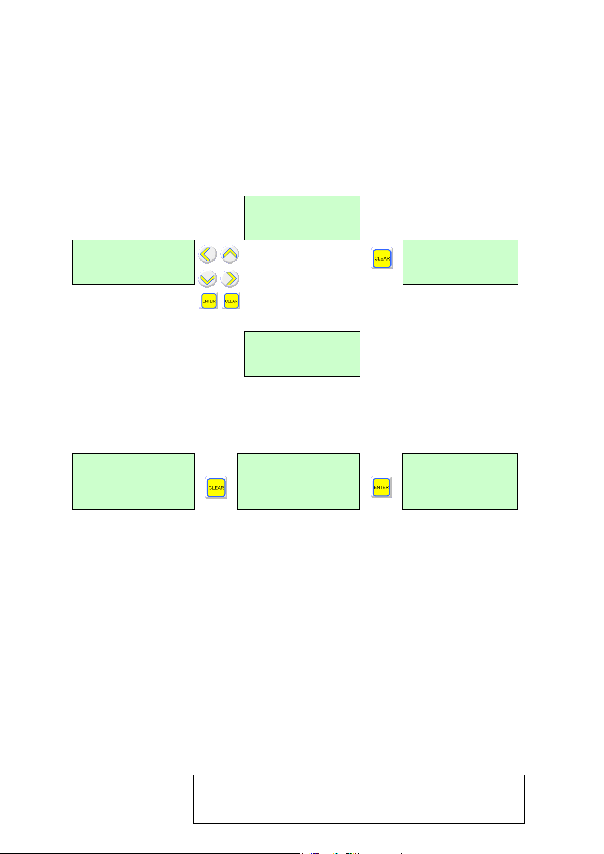
4.1 Setting mode (In / Out)
Press any key except CLEAR to enter in setting mode.
If no parameter has been modified, exit the mode by pressing the CLEAR key:
MAIN MENU
MESUREMENTS
CURRENT I1
0.0 A
Or
CURRENT I1
0.0 A
MAIN MENU
MAINTENANCE
* « Measurements Menu» for the V1.24 and V2.xx Firmware and, « Maintenance Menu»
from the V3.00 Firmware.
If a parameter has been modified, confirm the exit from setting mode:
MAIN MENU
PHASE EARTH FLT.
QUIT SETTINGS
MODE ?
CURRENT I1
0.0 A
Without any operation, return to default screen is carried out automatically after 5 minutes.
This document is the sole property of
ICE. No duplication nor release to third
party is allowed without prior
authorization
User’s Guide
NPM800 – NPM800R
Date : 05/2013
Edition :30/01/2014
Folio : 9
Indice : g
NPM800RE
Page 11
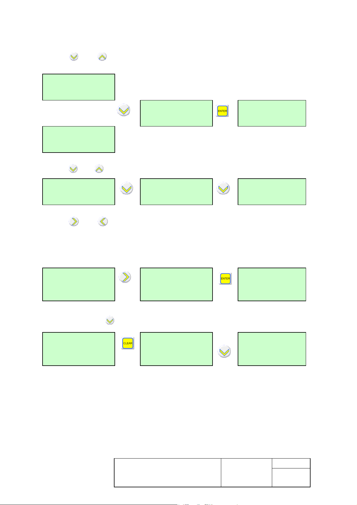
4.2 Modification of a parameter
Use the and keys to select a menu, then press the ENTER key to access the first
parameter.
MAIN MENU
MEASUREMENTS
Or
MAIN MENU
MAIN MENU
PHASE EARTH FLT.
SETTING
set 1
MAINTENANCE
Use the and keys to access the various parameters in the menu:
SHORT CIRCUIT
Active
SHORT CIRC.DELAY
0,50 s
SHORT CIRC.THRES
3,0 * In
Use the and keys to modify the parameter.
You must confirm your change using the ENTER key after each parameter modification.
After storing the new parameter value, next parameter is displayed:
SHORT CIRC.DELAY
SHORT CIRC.DELAY
SHORT CIRC.THRES
0.60 s
0.70 s
3,0 * In
Use the CLEAR and keys to change menu:
SHORT CIRC.DELAY
0,70 s
MAIN MENU
PHASE EARTH FLT
MAIN MENU
GENERIC FUNCTION
Leaving any sub menu with the CLEAR key will lead to the above menu.
This document is the sole property of
ICE. No duplication nor release to third
party is allowed without prior
authorization
User’s Guide
NPM800 – NPM800R
Date : 05/2013
Edition :30/01/2014
Folio : 10
Indice : g
NPM800RE
Page 12
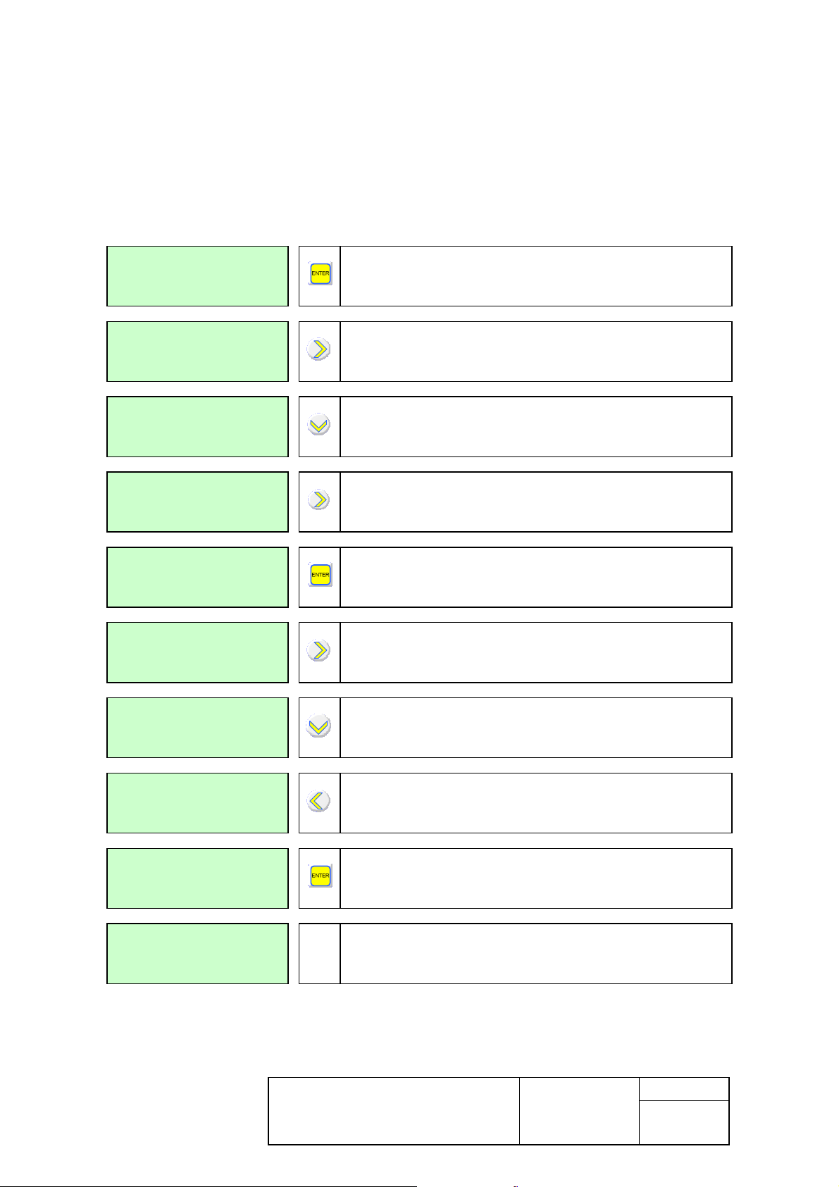
4.3 Access code
On first modification of a parameter, the software requests the access code.
The factory-programmed code is " ICE1 ".
To enter your own personalised code, use the " CHANGE CODE " menu. The code can be
composed up to four alphanumeric characters.
The following example shows how to replace code "AA" with " 99 ":
MAIN MENU
Press on « ENTER » to confirm
CHANGE CODE
OLD PASSWORD
_
OLD PASSWORD
I
Press on until obtaining the letter « A »
Press on to displace the cursor « _ »
OLD PASSWORD
I_
OLD PASSWORD
AA
NEW PASSWORD
_
NEW PASSWORD
9
NEW PASSWORD
9_
NEW PASSWORD
99
Press on until obtaining the letter « A »
Press on « ENTER » to confirm
Press on until obtaining the letter « 9 »
Press on to displace the cursor « _ »
Press on until obtaining the letter « 9 »
Press on « ENTER » to confirm
MAIN MENU
CHANGE CODE
In case of loss of the code, contact us to obtain an emergency password for your
configuration.
This document is the sole property of
ICE. No duplication nor release to third
party is allowed without prior
authorization
User’s Guide
NPM800 – NPM800R
Date : 05/2013
Edition :30/01/2014
Folio : 11
Indice : g
NPM800RE
Page 13
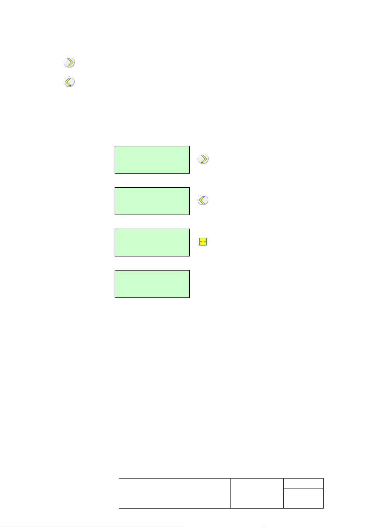
4.4 Assignment of output units
Relays assigned to a function are displayed with « ».
Key allows displacing the cursor « _ » on the relay(s) to assign.
Key allows assigning or not the relays used by the functions.
Example: assignment of relay B to TRIP Io > low earth function. At the beginning, no function
was assigned to this relay.
Caution: do not forget to confirm by ENTER key.
EARTH TRIP RELAY
A_ B C D
EARTH TRIP RELAY
A B_ C D
EARTH TRIP RELAY
A B C D
EARTH TRIP RELAY
E F G
This document is the sole property of
ICE. No duplication nor release to third
party is allowed without prior
authorization
User’s Guide
NPM800 – NPM800R
Date : 05/2013
Edition :30/01/2014
Folio : 12
Indice : g
NPM800RE
Page 14

Press on CLEAR key to leave
V1.24
5. Menu list
5.1 Access to main menus
The following menus enable setting of the available functions. Each one allows access to the
parameters of adjustment and ensures their coherence.
CURRENT I1
100.0 A
MAIN MENU
MEASUREMENTS
Press on any key other than CLEAR
to enter the parameter setting mode
Real time measures (firmware
and V2.xx)
the parameter setting mode
Cf. chapter 4 to select a
menu
Or
MAIN MENU
MAINTENANCE
MAIN MENU
PHASE EARTH FLT.
MAIN MENU
GENERIC FUNCTION
MAIN MENU
THERMAL IMAGE
MAIN MENU
STARTING FCT.
MAIN MENU
LOSS OF LOAD
Real time measures (since V3.00
firmware)
Parameters of the functions 50 and
51N
Parameters of the customized
functions
Parameters of the thermal overload
function
Parameters of the functions 51LR
and 66 (starts)
Parameters of the minimum load
function (pump unpriming) 37
MAIN MENU
UNBALANCE
MAIN MENU
LOAD SHEDDING
MAIN MENU
TELECONTROL
This document is the sole property of
ICE. No duplication nor release to third
party is allowed without prior
authorization
Parameters of the function 46
(unbalance)
Parameters of the load-shedding
function
Parameters of the remote control
option
User’s Guide
NPM800 – NPM800R
NPM800RE
Date : 05/2013
Edition :30/01/2014
Folio : 13
Indice : g
Page 15

MAIN MENU
PERTURBOGRAPHY
Information about disturbance
recording
MAIN MENU
Information about counters
COUNTERS
MAIN MENU
OPERATION
Operating parameters to be defined
at commissioning
MAIN MENU
RS485 COMMS
Configuration of the Modbus RS485
communication option
(if option available)
MAIN MENU
Change of the access code
CHANGE CODE
MAIN MENU
Information about protection
INFORMATION
MAIN MENU
Reading of the event log
EVENTS
Leaving any sub menu with the CLEAR key will lead to the above menu.
This document is the sole property of
ICE. No duplication nor release to third
party is allowed without prior
authorization
User’s Guide
NPM800 – NPM800R
Date : 05/2013
Edition :30/01/2014
Folio : 14
Indice : g
NPM800RE
Page 16
5.2 Measurement menu (V1.24 and V2.xx firmware only)
This menu displays any real time measurement of the protection, as well as the values kept
in memory.
MAIN MENU
MEASUREMENTS
Available real time measures
CURRENT I1
0.0 A
CURRENT I3
0.0 A
CURRENT Io
0.00 A
FREQUENCY
50.00 Hz
THERMAL IMAGE
0.0 %
NEGATIVE SEQ.
0.0 %
Measure of the phase 1 primary
current
Measure of the phase 3 primary
current
Measure of the earth Io primary
current
Measure of the network frequency
Measure of the thermal state of
motor
Measure of the rate of negative
sequence of current
0.0 to 65535A
0.0 to 65535A
0.0 to 65535A
45 to 55 if Fn = 50 Hz
55 to 65 if Fn = 60 Hz
0.0 to 500 %
POSITIVE SEQ.
0.0 %
Measure of the rate of positive
sequence of current
CURRENT START
0.0 A
Maximum current measured during
last start (firmware 2.xx)
0 to 65535A
STARTS ALLOWED
4
number of authorized remaining
starts
Inactive if function MAX
NBR STARTS inactive.
START TIME
Duration of the last start
1 to 200 s
3.00 s
This document is the sole property of
ICE. No duplication nor release to third
party is allowed without prior
authorization
User’s Guide
NPM800 – NPM800R
Date : 05/2013
Edition :30/01/2014
Folio : 15
Indice : g
NPM800RE
Page 17

AVER. CURRENT I1
100.0 A
AVER. CURRENT I3
100.0 A
Value of the average primary current
of phase 1
Value of the average primary current
of phase 3
0 to 65535A
0 to 65535A
AVER. CURRENT I0
0.0 A
SETTING
set 1
02/07/01
10:19:42
Value of the average earth-fault
primary current
Display of the active setting group
Day / Month / Year
Hour / minute / second
0 to 65535A
set 1 or set 2
This document is the sole property of
ICE. No duplication nor release to third
party is allowed without prior
authorization
User’s Guide
NPM800 – NPM800R
Date : 05/2013
Edition :30/01/2014
Folio : 16
Indice : g
NPM800RE
Page 18

5.3 Maintenance menu (since V3.00 firmware)
This menu displays any real time measurement of the protection, as well as the values kept
in memory.
MAIN MENU
MAINTENANCE
CURRENT I1
0.0 A
Available real time measures
Measure of the phase 1 primary
current
0.0 to 65535A
CURRENT I3
0.0 A
CURRENT Io
0.00 A
FREQUENCY
50.00 Hz
THERMAL STATE
0.0 %
NEGATIVE SEQ.
0.0 %
POSITIVE SEQ.
0.0 %
Measure of the phase 3 primary
0.0 to 65535A
current
Measure of the earth Io primary
0.0 to 65535A
current
Measure of the network frequency
45 to 55 if Fn = 50 Hz
55 to 65 if Fn = 60 Hz
Measure of the thermal state of motor 0.0 to 500 %
Measure of the rate of negative
sequence of current
Measure of the rate of positive
sequence of current
LAST START CURR.
0.0 A
Maximum current measured during
last start (firmware 2.xx)
0 to 65535A
LAST START DATE
01/12 01:52:47
Date of last start
Day/Month Hour : Minute : Second
MAX START CURR.
0.0 A
Maximum current measured during all
starts
0 to 65535A
STARTS ALLOWED
4
This document is the sole property of
ICE. No duplication nor release to third
party is allowed without prior
authorization
number of authorized remaining starts
User’s Guide
NPM800 – NPM800R
Date : 05/2013
Edition :30/01/2014
Inactive if function MAX
NBR STARTS inactive.
Folio : 17
Indice : g
NPM800RE
Page 19

fault primary
LAST START TIME
3.00 s
Duration of the last start
1 to 200 s
MAX START TIME
0.00 s
OPERATING TIME
0 h 0 mn
SERVICE TIME
4h
AVER. CURRENT I1
100.0 A
AVER. CURRENT I3
100.0 A
AVER. CURRENT I0
0.0 A
Maximum duration measured during
all starts
hour(s) and minute(s) counter since
the last start
Counter of running hours since the
commissioning
Value of the average primary current of
phase 1
Value of the average primary current of
phase 3
Value of the average earthcurrent
1 to 200 s
0 to 65535 h
0 to 59 mn
0 to 65535 h
0 to 65535A
0 to 65535A
0 to 65535A
SETTING
Display of the active setting group
set 1
E1E2E3E4E5E6E7E8
Display of the digital inputs
0 0 0 0 0 0 0 0
WD A B C D E F G
Display of the digital outputs
1 0 0 0 0 0 0 0
REL. HOLD. RESET
Confirm : ENTER
Reset of latching output relays
ANSI 86*
02/07/01
10:19:42
Day / Month / Year
Hour / minute / second
* for ≥V2.20 Firmware , see « Counters » menu
set 1 or set 2
0 if inactive or 1 if active
0 if inactive or 1 if active
This document is the sole property of
ICE. No duplication nor release to third
party is allowed without prior
authorization
User’s Guide
NPM800 – NPM800R
NPM800RE
Date : 05/2013
Edition :30/01/2014
Folio : 18
Indice : g
Page 20

See chap 4 to choose a relay
See chap 4 to choose a relay
5.4 Phase/earth fault menu, after starting
This menu allows the setting of the phases and earth fault over current functions: setting in
and out of order, choice of the types of time delay and curves, adjustment of thresholds,
assignment of the output units.
This configuration must be carried out successively for each of the two settings groups if they
are to be used alternatively.
MAIN MENU
PHASE EARTH FLT.
SETTING
set 1
Parameters of the ANSI 50, 51N
functions
Choose the setting group
set 1 or set 2
SHORT CIRCUIT
Active
SHORT CIRC.DELAY
0.06 s
SHORT CIRC.THRES
3.0 * In
SHORT C.INST.REL
A B C D
SHORT C.INST.REL
E F G
SHORT C.TRIP.REL
A B C D
Choose Active to use the phase to
phase short-circuit function
Set the value of time delay of the
phase to phase short-circuit function
Set the threshold of the phase to
phase short-circuit function
Select relay to assign to the shortcircuit instantaneous function
Select relay to assign to the shortcircuit trip function
Active or Inactive
0.04 to 3 s
3.0 to 12.0 * In
or to modify the assignment
(relays D, E, F, G if option
available)
or to modify the assignment
SHORT C.TRIP.REL
E F G
EARTH FAULT
Active
INHIBITION Io
Active
This document is the sole property of
ICE. No duplication nor release to third
party is allowed without prior
authorization
Choose Active to use the earth fault
function
Choose Active to use the earth fault
function during the start
User’s Guide
NPM800 – NPM800R
Date : 05/2013
Edition :30/01/2014
NPM800RE
(relays D, E, F, G if option
available)
Active or Inactive
Active or Inactive
Folio : 19
Indice : g
Page 21

Select relay to assign to the earth fault
lay
Select relay to assign to the earth fault
See chap 4 to choose a relay
EARTH FLT DELAY
0.06 s
Set the value of the time delay of
earth fault function
0.04 to 3 s
EARTH FLT THRESH
0.1 * In
EARTH INST.RELAY
A B C D
EARTH INST. RELAY
E F G
EARTH TRIP RELAY
A B C D
EARTH TRIP RELAY
E F G
Set the value of the threshold of earth
fault function
instantaneous function
trip function
0.03 to 0.4 * In
See chap 4 to choose a re
or to modify the assignment
(relays D, E, F, G if option
available)
or to modify the assignment
(relays D, E, F, G if option
available)
This document is the sole property of
ICE. No duplication nor release to third
party is allowed without prior
authorization
User’s Guide
NPM800 – NPM800R
NPM800RE
Date : 05/2013
Edition :30/01/2014
Folio : 20
Indice : g
Page 22

See chap 4 to choose a relay
5.5 Generic functions menu
This menu allows the parameter setting of 4 or 8 (according option or relay type) customized
functions: setting in and out of order, adjustment of the time delays, assignment of the output
units and assignment of a digital input.
MAIN MENU
GENERIC FUNCTION
FCT GENERIC 1
Inactive
Parameters of the customized
functions
Choose Trip or Report to use
function 1.
Trip or Disable or Report*
TEMP GENERIC 1
0.06 s
RELAY GENERIC 1
A B C D
RELAY GENERIC 1
E F G
DIG.INP.GENER. 1
Input 1
NAME GENERIC 1
ALARM AERO
..................
..............
Set the time delay of function 1
Select relay to assign to function 1
Display of input selected for function
1
Display of label of function 1
0.04 to 300.00s
or to modify the assignment
(relays D, E, F, G if option
available)
No input, Input 1 to 8 (or 1 to
4 according option)
No input, Input 1 to 8 (or 1 to
4 according option)
* The « Report » mode is available since V2.20 firmware.
This document is the sole property of
ICE. No duplication nor release to third
party is allowed without prior
authorization
User’s Guide
NPM800 – NPM800R
NPM800RE
Date : 05/2013
Edition :30/01/2014
Folio : 21
Indice : g
Page 23

Set the value of the thermal overload
See chap 4 to choose a relay
5.6 Thermal overload menu
This menu allows the parameter setting of the thermal overload function: setting in and out
of order, type of thermal overload, adjustment of the thermal time-constant, adjustment of the
thermal trip and alarm thresholds, assignment of the output units for alarm and trip.
MAIN MENU
THERMAL IMAGE
SETTING
set 1
Parameters of the thermal overload
option.
Choose the setting group
set 1 or set 2
THERMAL OVERLOAD
Active
HEATING CONST
40 mn
COOLING CONST
4.0 * CST. ECHAUF
START FACTOR
50 %
NEG. SEQ. FACTOR
3
THERM THR. Iref
0.40 * In
TH. TRIP RELAY
A B C D
Choose Active to use thermal
overload function
time-constant
Set the cooling constant
Set the coefficient calculation of the
thermal overload (starting mode)
Set the negative sequence factor K
(thermal heating)
Set the thermal reference current
Iref, used by thermal overload
function
Select relay to assign to the thermal
overload trip function
Active or Inactive
4 to 64 minutes
1.0 to 6.0 * heating constant
50 to 100 %
0 to 9
0.40 to 1.3 x In
or to modify the assignment
TH. TRIP RELAY
E F G
TH.ALARM THRESH
80 %
This document is the sole property of
ICE. No duplication nor release to third
party is allowed without prior
authorization
Set the thermal alarm threshold
User’s Guide
NPM800 – NPM800R
NPM800RE
(relays D, E, F, G if option
available)
80 to 100 %
Date : 05/2013
Edition :30/01/2014
Folio : 22
Indice : g
Page 24

See chap 4 to choose a relay
TH. ALARM RELAY
A B C D
Select relay to assign to the thermal
alarm function
or to modify the assignment
TH. ALARM RELAY
E F G
(relays D, E, F, G if option
available)
This document is the sole property of
ICE. No duplication nor release to third
party is allowed without prior
authorization
User’s Guide
NPM800 – NPM800R
NPM800RE
Date : 05/2013
Edition :30/01/2014
Folio : 23
Indice : g
Page 25

Number of starts, too long start, rotor
See chap 4 to choose a relay
5.7 Start menu
This menu allows the parameter setting of the too long start, locked rotor, limitation of the
number of start and inhibition of hot start functions: setting in and out of order, adjustment of
the start motor and inhibition of hot start threshold, adjustment of the time delays (start,
locked rotor, restarting), assignment of the output units for the trip (too long start, locked rotor
and inhibition of start).
MAIN MENU
STARTING FCT.
SETTING
set 1
stall after start period
Choose the setting group
set 1 or set 2
LONG ST/ST.ROTOR
Active
START THRESHOLD
2.0 * Iref
START DELAY
20 s
STALLED DELAY
0.2 s
REL.LONG S/ROT S
A B C D
Choose Active for too long start and
locked rotor (51 LR)
Detection Threshold of the start of
the motor (Iref: thermal current of
reference)
Maximum duration of start for too
long start
Time delay to detect a locked rotor
after a start
Select the too long start and locked
rotor relays (51 LR)
Active or Inactive
1.0 to 10.0 * Iref
2 à 200 s
0.2 to 2.0 s
or to modify the assignment
REL.LONG S/ROT S
E F G
MAX NBR STARTS
Active
MAX NBR STARTS
3
This document is the sole property of
ICE. No duplication nor release to third
party is allowed without prior
authorization
Choose Active for the maximum
number of starts function
Maximum number of starts during
time delay
User’s Guide
NPM800 – NPM800R
Date : 05/2013
Edition :30/01/2014
NPM800RE
(relays D, E, F, G if option
available)
Active or Inactive
1 to 4
Folio : 24
Indice : g
Page 26

See chap 4 to choose a relay
AUTHORIS. DELAY
15 min
BLOCKING DELAY
15 min
Set the time delay for counting the
number of starts
Duration of the inhibition of restarting
15 to 60 min
15 to 60 min
HOT START
Active
HOT START THRESH
40 %
START RELAY
A B C D
START RELAY
E F G
Choose Active for the hot motor
inhibition of start function
Setting of the threshold of inhibition
of hot motor starting
Select relay to assign to inhibition of
hot motor starting
Active or Inactive
40 to 100 %
or to modify the assignment
(relays D, E, F, G if option
available)
This document is the sole property of
ICE. No duplication nor release to third
party is allowed without prior
authorization
User’s Guide
NPM800 – NPM800R
NPM800RE
Date : 05/2013
Edition :30/01/2014
Folio : 25
Indice : g
Page 27

to choose a relay
5.8 Loss of load menu (or pump unpriming)
This menu allows setting operation on loss of load.
MAIN MENU
LOSS OF LOAD
SETTING
set 1
Parameters of the minimum load
function (pump unpriming) 37
Choose the setting group
set 1 or set 2
LOSS OF LOAD
Active
MIN THRESHOLD Id
0.20 * In
LOAD LOSS DELAY
2 s
LOAD LOSS RELAY
A B C D
LOAD LOSS RELAY
E F G
Choose Active to use the loss of
load function
Minimum direct current for loss of
load threshold
Set the time delay of the loss of load
function
Select relay to assign to the loss of
load function
Active or Inactive
0.10 to 2.40 * In
0.05 to 120 s
See chap 4
or to modify the assignment
(relays D, E, F, G if option
available)
This document is the sole property of
ICE. No duplication nor release to third
party is allowed without prior
authorization
User’s Guide
NPM800 – NPM800R
NPM800RE
Date : 05/2013
Edition :30/01/2014
Folio : 26
Indice : g
Page 28

See chap 4 to choose a relay
5.9 Unbalance menu
This menu allows setting the unbalance function.
MAIN MENU
UNBALANCE
SETTING
set 1
Choose the setting group
set 1 or set 2
UNBALANCE
Active
NEG.SEQ. THRESH
0.20 * In
NEG.SEQ.DELAY
1 s
TRIP.MIN.N.S.DEL
0.06 s
UNBAL.INST.RELAY
A B C D
UNBAL.INST.RELAY
E F G
Choose Active to use unbalance
and phase reversal function
Set the negative sequence
threshold
Set the dependent time curve
Set the minimum duration of trip
Select relays for the instantaneous
unbalance and phase reversal
functions
Active or Inactive
0.20 to 0.80 * In
1 to 10 s
0.04 to 10 s
or to modify the assignment
(relays D, E, F, G if option
available)
UNBAL.TRIP RELAY
A B C D
UNBAL.TRIP RELAY
E F G
This document is the sole property of
ICE. No duplication nor release to third
party is allowed without prior
authorization
Select relays for the time delayed
unbalance and phase reversal trip
functions
User’s Guide
NPM800 – NPM800R
Date : 05/2013
Edition :30/01/2014
NPM800RE
See chap 4 to choose a relay
or to modify the assignment
(relays D, E, F, G if option
available)
Folio : 27
Indice : g
Page 29

See chap 4 to choose a relay
5.10 Load-shedding menu
This menu allows setting the load-shedding function on order external and the restarting of
the motor.
5.10.1 Load-shedding menu (V1.24 and V2.xx firmware)
MAIN MENU
DELOAD
SETTING
set 1
DELOAD
Active
DELOAD DELAY
0.10 s
DELOAD RELAY
A B C D
DELOAD RELAY
E F G
Load-shedding on external order
and re acceleration parameters
Choose the setting group
set 1 or set 2
Choose Active to use the load-
Active or Inactive
shedding function
Set time delay of load-shedding
0.06 to 120 s
Select relay to assign for the loadshedding function.
or to modify the assignment
(relays D, E, F, G if option
available)
5.10.2 Load-shedding menu (since V3.00 firmware)
MAIN MENU
LOAD SHEDDING
SETTING
set 1
LOAD SHEDDING
Active
LOAD SHED DELAY
0.10 s
This document is the sole property of
ICE. No duplication nor release to third
party is allowed without prior
authorization
Load-shedding on external order
and re acceleration parameters
Choose the setting group
set 1 or set 2
Choose Active to use the load-
Active or Inactive
shedding function
Set time delay of load-shedding
0.06 to 120 s
User’s Guide
NPM800 – NPM800R
Date : 05/2013
Edition :30/01/2014
Folio : 28
Indice : g
NPM800RE
Page 30

See chap 4 to choose a relay
LOAD SHED RELAY
A B C D
Select relay to assign for the loadshedding function.
or to modify the assignment
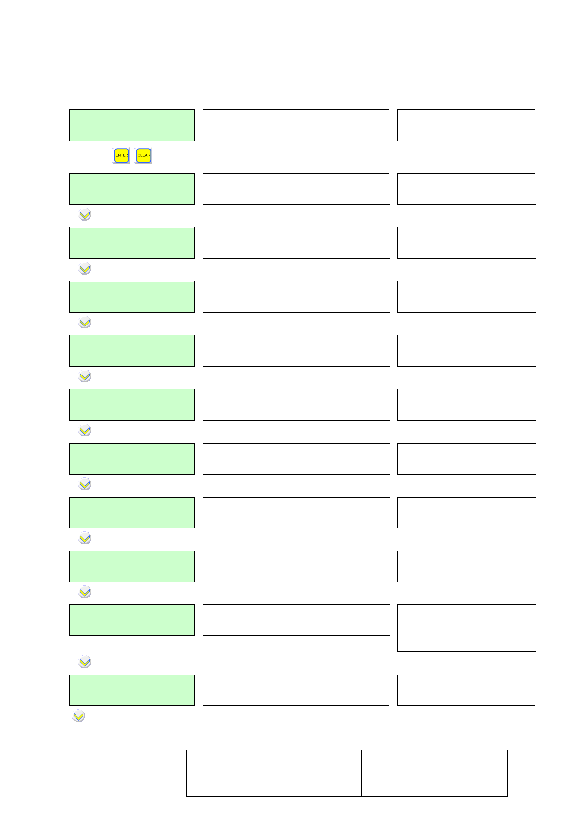
LOAD SHED RELAY
E F G
(relays D, E, F, G if option
available)
This document is the sole property of
ICE. No duplication nor release to third
party is allowed without prior
authorization
User’s Guide
NPM800 – NPM800R
NPM800RE
Date : 05/2013
Edition :30/01/2014
Folio : 29
Indice : g
Page 31

5.11 Remote control menu
This menu allows enabling the remote control functions, choice of the level of load-shedding,
choice of the reclose time delay assignment of the trip and reclose relays and choice of the
reclose pulse.
This menu is available if the communication option is present.
5.11.1 Telecontrol menu (V1.24 and V2.xx Firmware)
MAIN MENU
TELECONTROL
TELECONTROL
Active
LOAD SHED LEVEL
6
RE-LOAD DELAY
20.00 s
TRIP RELAY
A B C D
TRIP RELAY
E F G
Information about remote control
option
Choose Active to use remote control
option
Set the level of load-shedding.
Set the time delay before reclosing
Select relay to assign to remote
control trip
Active or Inactive (Active if
communication available)
1 to 6 (Level 6 inhibits the
load-shedding function)
1.00 s to 120.00 s
See chap 4 to choose a relay
or to modify the assignment
(D, E, F, G relay if option
available)
RECLOSE RELAY
A B C D
Select relay to assign to remote
control close order
See chap 4 to choose a relay
or to modify the assignment
RECLOSE RELAY
E F G
(D, E, F, G relay if option
available)
RECLOSE PULSE
200 ms
Setting of the minimum duration of
reclosing pulse
100 to 500 ms
O/O INPUT
Input 1
Display of input assigned to the O/O
interlock position (CB closed)
No input, Input 1 to 8 (or 1 to
4 according option)
This document is the sole property of
ICE. No duplication nor release to third
party is allowed without prior
authorization
User’s Guide
NPM800 – NPM800R
Date : 05/2013
Edition :30/01/2014
Folio : 30
Indice : g
NPM800RE
Page 32

C/O INPUT
Input 2
Display of input assigned to the F/O
interlock position (CB open)
No input, Input 1 to 8 (or 1 to
4 according option)
LOCAL INPUT
Input 3
Display of input assigned to the
LOCAL operation mode
DISTANT INPUT
Input 4
Display of input assigned to the
DISTANT operation mode
5.11.2 Telecontrol menu (since V3.00 Firmware)
MAIN MENU
TELECONTROL
TELECONTROL
Active
LOAD SHED LEVEL
2
Information about remote control
option
Choose Active to use remote control
option
(Available if the communication option is present)
Set the level of load-shedding. Level 6
inhibits the load-shedding function
(Available if the communication option is present)
No input, Input 1 to 8 (or 1 to
4 according option)
No input, Input 1 to 8 (or 1 to
4 according option)
Active or Inactive
1 to 6
RE-LOAD DELAY
20.00 s
Set the time delay before reclosing
(Available if the communication option is present)
1.00 s to 120.00 s
TRIP RELAY
A B C D
Select relay to assign to remote control
trip order
See chap 4 to choose a relay
or to modify the assignment
TRIP RELAY
E F G
(D, E, F, G relay if option
available)
RECLOSE RELAY
A B C D
Select relay to assign to remote control
close order
See chap 4 to choose a relay
or to modify the assignment
RECLOSE RELAY
E F G
(D, E, F, G relay if option
available)
This document is the sole property of
ICE. No duplication nor release to third
party is allowed without prior
authorization
User’s Guide
NPM800 – NPM800R
Date : 05/2013
Edition :30/01/2014
Folio : 31
Indice : g
NPM800RE
Page 33

Display of input assigned to the LOCAL
RECLOSE PULSE
200 ms
Setting of the minimum duration of
reclosing pulse
100 to 500 ms
O/O INPUT
Input 1
C/O Input
Input 2
LOCAL INPUT
No input
DISTANT INPUT
Input 4
Display of input assigned to the O/O
interlock position (CB closed)
Display of input assigned to the F/O
interlock position (CB open)
operation mode
option is present and if the management of input(s)
number Local/distant is carried out with 2 digital
inputs)
(Available if the communication
Display of input assigned to the
DISTANT operation mode
communication option is present)
(Available if the
No input, Input 1 to 8 (or 1 to
4 according option)
No input, Input 1 to 8 (or 1 to
4 according option)
No input, Input 1 to 8 (or 1 to
4 according option)
No input, Input 1 to 8 (or 1 to
4 according option)
5.12 Disturbance menu
This menu is used to configure the parameters of the disturbance recording.
MAIN MENU
PERTURBOGRAPHY
PRE-TIME
30 period(s)
PERTURBO. INPUT
E5
REL. DISTURB.
A B C D
REL. DISTURB.
E F G
Parameters of the disturbance
recording function
Set pre time
Display of input assigned to the
external disturbance recording
triggering
Select relay to assign to
disturbance recording trip
(Available from V3.00 Firmware )
1 to 52 periods
No input, Input 1 to 8 (or 1
to 4 according option)
See chap 4 to choose a
relay or to modify the
assignment
(relays D, E, F, G if option
available)
This document is the sole property of
ICE. No duplication nor release to third
party is allowed without prior
authorization
User’s Guide
NPM800 – NPM800R
NPM800RE
Date : 05/2013
Edition :30/01/2014
Folio : 32
Indice : g
Page 34

5.13 Counters menu
This menu allows the parameter setting of the counters: display of cut A², number of circuit
breaker operations, current maximeters and reset of the counters.
MAIN MENU
COUNTERS
A2 CUTOFF I1
100000.0 kA2
A2 CUTOFF I3
100000.0 kA2
RAZ A2 CUTOFF
Confirm: ENTER
NBER OPERATIONS
100
RESET NB OPERAT.
Confirm : ENTER
REL. HOLD RESET
Confirm : ENTER
MAX. METER I1
100 A
MAX. METER I3
100 A
MAX. METER I0
10.0 A
MAX. METER RESET
Confirm : ENTER
Parameters of the counters
function
Display of cut A² of phase 1
Display of cut A² of phase 3
Reset of cut A² with ENTER key
Display of the number of operations
of the circuit breaker
Reset of the number of operations
of the circuit breaker
ANSI 86*, reset of the latching
function for the output relay
Display of the current maximeter on
phase 1
Display of the current maximeter on
phase 3
Display of the current maximeter on
earth
Reset of current maximeter with
ENTER key
*The “REL.HOLD.RESET” function is available since V2.20 Firmware. (For V3.00, see the
« Maintenance » menu).
This document is the sole property of
ICE. No duplication nor release to third
party is allowed without prior
authorization
User’s Guide
NPM800 – NPM800R
Date : 05/2013
Edition :30/01/2014
Folio : 33
Indice : g
NPM800RE
Page 35

5.14 Operation menu
This menu allows the parameter setting of the operation function: choice of the language,
adjustment of LCD contrast, parameter setting of the values of the phase and earth-fault
CTs, display of the digital input corresponding to set 2, trip pulse, maximum of cut A² and
number of operations of the circuit breaker, assignment of the relays for circuit breaker failure
and discrepancy, average current.
5.14.1 Operation menu (1.24 and V2.xx firmware)
MAIN MENU
OPERATION
LANGUAGE
English
ADJUST LCD
200
I NOMINAL PRIM.
1000 A
Io NOMINAL PRIM.
100 A
SET 2 INPUT
E6
CLEAR REL. INPUT
No input
TRIP PULSE
100 ms
MAX A2 CUTOFF
200000 kA2
MAX NBER OPERAT.
9999
Operating parameters to be defined
at commissioning
Choice of the language used locally
by protection
Adjustment of the angle of vision of
the LCD display
Set the value of the phase primary
rated current of the CTs
Set the value of the earth primary
rated current of the CT
Display of input assigned to setting
group 2
Display of input assigned to reset
of relays
Setting of minimum duration of trip
pulse
Adjustment of the maximum of cut
A²
Adjustment of maximum number of
circuit breaker operations
French, English, Italian or
Spanish
70 to 255
1 to 10000 A
1 to 10000 A
No input, Input 1 to 8 (or 1
to 4 according option)
No input, Input 1 to 8 (or 1
to 4 according option)
100 to 500 ms
1 to 64 000 000 KA²
1 to 10000
This document is the sole property of
ICE. No duplication nor release to third
party is allowed without prior
authorization
User’s Guide
NPM800 – NPM800R
Date : 05/2013
Edition :30/01/2014
Folio : 34
Indice : g
NPM800RE
Page 36

ap 4 to choose a relay
RELAY C.B. FAULT
A B C D
Select relay to assign to the circuit
breaker failure function
RELAY C.B. FAULT
E F G
RELAY DISC. L/D
A B C D
Select relay to assign to the
local/distant discrepancy function
RELAY DISC. L/D
E F G
I AVERAGE
in 30 mn
Adjustment of the time for
calculation of average values and
maximeters
NB OF INPUTS L/D
1 input
Number of input(s), configurable for
the management of the
Local/Distant mode
5.14.2 Operation menu (since V3.00 firmware)
See ch
or to modify the assignment
(relays D, E, F, G if option
available)
(remote control in service)
(relays D, E, F, G if option
available)
5 to 60 min
1 or 2
MAIN MENU
OPERATION
LANGUAGE
English
ADJUST LCD
200
I NOMINAL PRIM.
1000 A
Io NOMINAL PRIM.
100 A
SET 2 INPUT
E6
Operating parameters to be defined
at commissioning
Choice of the language used locally
by protection
Adjustment of the angle of vision of
the LCD display
Set the value of the phase primary
rated current of the CTs
Set the value of the earth primary
rated current of the CT
Display of input assigned to setting
group 2
French, English, Italian or
Spanish
70 to 255
1 to 10000 A
1 to 10000 A
No input, Input 1 to 8 (or 1 to 4
according option)
This document is the sole property of
ICE. No duplication nor release to third
party is allowed without prior
authorization
User’s Guide
NPM800 – NPM800R
Date : 05/2013
Edition :30/01/2014
Folio : 35
Indice : g
NPM800RE
Page 37

CLEAR REL. INPUT
E5
TRIP PULSE
100 ms
MAX A2 CUTOFF
200000 kA2
MAX NBER OPERAT.
9999
RELAY C.B. FAULT
A B C D
RELAY C.B. FAULT
E F G
REL.L/R NO-COMPL
A B C D
REL.L/R NO-COMPL
E F G
NB OF INPUTS L/R
2 inputs
CONTROL CB POSIT
Inactive
Display of input assigned to reset
of relays
Setting of minimum duration of trip
pulse
Adjustment of the maximum of cut
A²
Adjustment of maximum number of
circuit breaker operations
Select relay to assign to the circuit
breaker failure function
Select relay to assign to nocomplementarity local/distant
function
Number of input(s), configurable for
the management of the
Local/Remote mode
Choose Active to use the
management of the CB position
No input, Input 1 to 8 (or 1 to 4
according option)
100 to 500 ms
1 to 64 000 000 KA²
1 to 10000
See chap 4 to choose a relay or
to modify the assignment
(D, E, F, G relay if option
available)
(remote control in service)
(D, E, F, G relay if option
available)
1 or 2 digital inputs
Active or Inactive
CLOS. LOC. INPUT
No input
Display of input assigned to the
closing in local
(configurable with PC software)
No input, Input 1 to 8 (or 1 to 4
according option)
This document is the sole property of
ICE. No duplication nor release to third
party is allowed without prior
authorization
User’s Guide
NPM800 – NPM800R
Date : 05/2013
Edition :30/01/2014
Folio : 36
Indice : g
NPM800RE
Page 38

TRIP. LOC. INPUT
No input
I AVERAGE
in 30 mn
UVR REL. ASSIG.
C D G
Display of input assigned to the
tripping in local
(configurable with PC software)
No input, Input 1 to 8 (or 1 to 4
according option)
Adjustment of the time for
5 to 60 min
calculation of average values and
maximeters
Select the relay(s) to be assigned in CB
under voltage release trip circuit (D and G if option available)
RELAY A
RECLOSE DJ
RELAY B
TRIP DJ
RELAY C
ALARM 9
RELAY D
OUTPUT D
RELAY E
OUTPUT E
RELAY F
OUTPUT F
Display the label of the output unit
A
Display the label of the output unit
B
Display the label of the output unit
C
Display the label of the output unit
D (if option available)
Display the label of the output unit
E (if option available)
Display the label of the output unit
F (if option available)
(configurable with the PC
software)
(configurable with the PC
software)
(configurable with the PC
software)
(configurable with the PC
software)
(configurable with the PC
software)
(configurable with the PC
software)
RELAY G
OUTPUT G
Display the label of the output unit
G (if option available)
(configurable with the PC
software)
This document is the sole property of
ICE. No duplication nor release to third
party is allowed without prior
authorization
User’s Guide
NPM800 – NPM800R
NPM800RE
Date : 05/2013
Edition :30/01/2014
Folio : 37
Indice : g
Page 39

5.15 Communication Modbus® menu (if option available)
This menu is used to set the parameters of the Modbus® communication function: slave
number, size, speed, activity and loop tests.
MAIN MENU
COMMUNIC. MODBUS
Or
MAIN MENU
RS485 COMMS
SLAVE NUMBER
2
Configuration of the Modbus RS485
communication option
Configuration of the Modbus RS485
communication option
Slave number of protection
V1.24 and V2.xx Firmware s
Since V3.00 Firmware
1 to 255
FORMAT
8b+0p+ASCII2s
SPEED
9600 bauds
RECEPT. TIMEOUT
0.10 s
ACTIVITY TIMEOUT
0.20 s
ACTIVITY TEST
Mes.Not Received
number of bits + parity + bits of stop
+ ASCII/Binary format
Parity: 1p = pair, 1i = odd,
0p= without
p0 = forced to 0, p1 = forced
to 1
Speed transmission on RS485 link
300, 600 ,1200 ,1800, 2400,
4800, 9600, 19200 38400,
57 600,115 200 bauds
Set the time delay of reception
0.10 to 20 s
timeout
Set the time delay of activity timeout 0.10 to 20 s
Test of the parameter setting and the
wiring of Modbus
message received / not
received: correct activity /
communication problem
5.16 Change of code menu
This menu allows change of code and is described in chapter Access Code.
This document is the sole property of
ICE. No duplication nor release to third
party is allowed without prior
authorization
User’s Guide
NPM800 – NPM800R
NPM800RE
Date : 05/2013
Edition :30/01/2014
Folio : 38
Indice : g
Page 40

5.17 Information menu
Information menu specifies the factory set characteristics of the protection, as well as the
wording assigned by the User.
5.17.1 Information menu (V1.24 and V2.xx firmware)
MAIN MENU
Information about protection
INFORMATIONS
NP.M 800
50 Hz
Type of protection
Rated frequency
PROC.VER. x.xx
Version of the software of
protection
PHASES RAT. 1 A
EARTH RAT. 1 A
Display of the phases and earth
ratings
NP 800
32 characters zone programmable with the setting software.
ICE
5.17.2 Menu informations (à partir de la Version V3.00)
50 or 60 Hz
1 A, 5 A, or CBCT
MAIN MENU
INFORMATIONS
NPM800
50 Hz
PROC. VER. 3.xx
PHASES RAT. 5 A
EARTH RAT. 5 A
ICE
NP800
SERIAL NUMBER
xx.xxxxxxx
Information about protection
Type of protection
50 Hz or 60 Hz
Rated frequency
Version of the software of
protection
Display of the phases and earth
1 A, 5 A, or CBCT
ratings
32 characters zone programmable with the setting
software.
Serial number of the protection
This document is the sole property of
ICE. No duplication nor release to third
party is allowed without prior
authorization
User’s Guide
NPM800 – NPM800R
Date : 05/2013
Edition :30/01/2014
Folio : 39
Indice : g
NPM800RE
Page 41

Active setting group when
6. Content of an event
Events are different according to information recorded when fault occurs. There are three
different types of structures of event.
They can be read with the local MMI, the setting software (RS232 link) and the Modbus
communication network.
6.1 Events generated on 50/51N/37/46 thresholds (NPM800 and NPM800R NPM800RE)
Events are recorded as soon as a trip or alarm threshold of the current functions is reached:
♦ INST PH FAULT
♦ TRIP PH FAULT
♦ INST Io FAULT
♦ TRIP Io FAULT
♦ INST UNBALA PH
♦ TRIP UNBALA PH
♦ TRIP START LON
♦ TRIP STALL ROT
♦ TRIP LOSS LOAD
♦ TRIP DELOAD
Detail of available information can be consulted for each event, in accordance with the list
below:
MAIN MENU
EVENTS
TRIP PH FAULT S
17/06 14:22:00 R
17/16/13
14:22:00.990
List of the last 250 events
Type of fault Start or End of fault
Day/Month Hour/Minute/Second - Dated event Relative/
Synchronous
Day: Month: Year
Hour: Minute: Second. Millisecond
SETTING
set 1
CURRENT I1
745 A
CURRENT I3
743 A
This document is the sole property of
ICE. No duplication nor release to third
party is allowed without prior
authorization
tripping set 1 or set 2
Current of phase 1 measured during the event
Current of phase 3 measured during the event
User’s Guide
NPM800 – NPM800R
Date : 05/2013
Edition :30/01/2014
NPM800RE
Folio : 40
Indice : g
Page 42

CURRENT Io
Earth-fault current measured during the event
0.1 A
NEGATIVE SEQ.
Rate of negative sequence current measured during the event
175,6 %
THERMAL STATE
Motor thermal state measured during the event
0 °
Using keys and allows to display further information about the fault.
This document is the sole property of
ICE. No duplication nor release to third
party is allowed without prior
authorization
User’s Guide
NPM800 – NPM800R
Date : 05/2013
Edition :30/01/2014
Folio : 41
Indice : g
NPM800RE
Page 43

Active setting group when tripping
6.2 Thermal overload event
Events are recorded as soon as a trip or alarm threshold of the voltage or frequency
functions is reached:
♦ ALRM THERM REP
♦ TRIP THERM REP
Detail of available information can be consulted for each event, in accordance with the list
below:
6.2.1 Alarm
ALRM THERM REP S
17/06 13:25:55 R
17/06/03
13:25:55.240
SETTING
set 1
CURRENT I1
2484 A
CURRENT I3
0 A
CURRENT Io
0.0 A
Type of fault Start or End of fault
Day/Month Hour/Minute/Second - Dated event
Relative/Synchronous
Day: Month: Year
Hour: Minute: Second. Millisecond
set 1 or
Phase 1 current measured during the event
Phase 3 current measured during the event
Earth fault current measured during the event
set 2
NEGATIVE SEQ.
90.0 %
THERMAL STATE
80 %
This document is the sole property of
ICE. No duplication nor release to third
party is allowed without prior
authorization
Rate of negative sequence current measured during the event
Motor thermal state measured during the event
User’s Guide
NPM800 – NPM800R
Date : 05/2013
Edition :30/01/2014
Folio : 42
Indice : g
NPM800RE
Page 44

Active setting group when tripping
6.2.2 Thermal trip
TRIP THERM REP E
17/06 13:25:59 R
17/06/03
13:26:59.920
SETTING
set 1
CURRENT I1
2490 A
CURRENT I3
0 A
CURRENT Io
0.0 A
Type of fault Start or End of fault
Day/Month Hour/Minute/Second - Dated event
Relative/Synchronous
Day / Month / Year
Hour: Minute: Second. Millisecond
set 1 or set 2
Phase 1 current measured at appearance of trip
Phase 3 current measured at appearance of trip
Earth fault current measured at appearance of trip
NEGATIVE SEQ.
Rate of negative sequence current
100 %
THERMAL STATE
Motor thermal state measured at appearance of trip
0 %
6.3 Customized inputs events
Events are recorded as soon as one of the customized input status changes.
♦ INST GENERIC
♦ TRIP GENERIC
Detail of available information can be consulted for each event, in accordance with the list
below:
TRIP GENERIC S
25:6 9:35:45 R
25/6/95
9:35:45.011
Type of fault Start or End of fault
Day/Month Hour/Minute/Second - Dated event
Relative/Synchronous
Day / Month / Year
Hour: Minute: Second. Millisecond
This document is the sole property of
ICE. No duplication nor release to third
party is allowed without prior
authorization
User’s Guide
NPM800 – NPM800R
NPM800RE
Date : 05/2013
Edition :30/01/2014
Folio : 43
Indice : g
Page 45

Active setting group when tripping
réglage 1 ou
Active setting
SETTING
set 1
set 2
6.4 Other events
The contents of the following events can be specified:
♦ ALRM NB OPERAS
♦ ALRM A2 CUTOFF
♦ CB FAIL
♦ DISC LOCA/REMO
♦ MODE REMOTE
♦ UNLISTED EVENT
♦ SETTING SET 2
♦ TRIP TELECONTR
♦ RECLOSE TELECO
♦ ALRM COIL
♦ ALRM CDE BREAK
Detail of available information can be consulted for each event, in accordance with the list
below:
ALRM NB OPERAS S
25:6 9:35:45 R
Type of fault Start or End of fault
Day:Month Hour:Minute:Second - Dated event
Relative/Synchronous
25/6/95
9:35:45.011
Day / Month / Year
Hour: Minute: Second. Millisecond
SETTING
group set 1 or set 2
set 1
6.5 Acknowledgement of events
The acknowledgement of the last event is carried out while pressing on CLEAR key:
TRIP THERM REP E
17/06 14:22:00 R
ACKNOWLEDGE ALL
Confirm : ENTER
CURRENT I1
100.0 A
6.6 Reading of the last 250 memorized events
After acknowledgement, the memorized events still may be read. It is necessary to use the
local sub-menu EVENTS of the MMI.
This document is the sole property of
ICE. No duplication nor release to third
party is allowed without prior
authorization
User’s Guide
NPM800 – NPM800R
NPM800RE
Date : 05/2013
Edition :30/01/2014
Folio : 44
Indice : g
Page 46

7. List of faults or operation messages
.
7.1 List of faults or operation message (Firmware V1.24 and V2.xx)
The following messages are locally displayed in real time on LCD display throughout fault.
7.2 Messages related to instantaneous type functions:
INSTANTANEOUS PHASE FAULT
INSTANTANEOUS EARTH FAULT
ALARM THERMAL REPLICA
INSTANTANEOUS UNBALANCE
7.3 Messages related to trip type functions:
TRIP PHASE FAULT
TRIP EARTH FAULT
TRIP THERMAL REPLICA
TRIP START TOO LONG
TRIP STALLED ROTOR
TRIP UNBALANCE PHASE
TRIP LOSS OF LOAD
TRIP DELOAD
TRIP BY TELECONTROL
TRIP GENERIC
7.4 Messages related to alarm type functions:
ALARM NUMBER OPERATIONS
ALARM A2 CUTOFF
CIRCUIT BREAKER FAIL
DISCORDANCE: LOCAL / REMOTE
ALARM COIL CIRCUIT BREAKER
ALARM CURRENT CIRCUIT BREAKER
7.5 Various messages:
RECLOSE BY TELECONTROL
LOSS AUX. SUPP*
RET. AUX.SUPP*
REMOTE MODE
UNLISTED EVENT
* The “LOSS AUX.SUPP.” and “RET.AUX.SUPP.” events are available since V2.20 version
This document is the sole property of
ICE. No duplication nor release to third
party is allowed without prior
authorization
User’s Guide
NPM800 – NPM800R
NPM800RE
Date : 05/2013
Edition :30/01/2014
Folio : 45
Indice : g
Page 47

Notes
: Disappearance of cut A² and number of operations alarms is done by resetting the
COUNTERS menu. To cause the disappearance of the last fault or operation message, it is
possible to press on CLEAR key of the keyboard.
7.6 List of faults or operation messages (Firmware V3.00)
The following messages are locally displayed in real time on LCD display throughout fault.
7.7 Messages related to instantaneous type functions:
INSTANTANEOUS PHASE FAULT
INSTANTANEOUS EARTH FAULT
ALARM THERMAL REPLICA
INSTANTANEOUS UNBALANCE
7.8 Messages related to trip type functions:
TRIP PHASE FAULT
TRIP EARTH FAULT
TRIP THERMAL REPLICA
TRIP START TOO LONG
TRIP STALLED ROTOR
TRIP UNBALANCE PHASE
TRIP LOSS OF LOAD
TRIP DELOAD
TRIP BY TELECONTROL
TRIP GENERIC
7.9 Messages related to alarm type functions:
ALARM NUMBER OPERATIONS
ALARM A2 CUTOFF
CIRCUIT BREAKER FAIL
NO COMPLEMENT. LOCAL / REMOTE
ALARM COIL CIRCUIT BREAKER
ALARM CURRENT CIRCUIT BREAKER
7.10 Various messages:
RECLOSE BY TELECONTROL
REMOTE MODE
UNLISTED EVENT
LOSS AUX.SUPP
RET. AUX.SUPP.
This document is the sole property of
ICE. No duplication nor release to third
party is allowed without prior
authorization
User’s Guide
NPM800 – NPM800R
NPM800RE
Date : 05/2013
Edition :30/01/2014
Folio : 46
Indice : g
Page 48

Notes:
Disappearance of cut A² and number of operations alarms is done by resetting the
COUNTERS menu.
To cause the disappearance of the last fault or operation message, it is possible to press on
CLEAR key of the keyboard.
This document is the sole property of
ICE. No duplication nor release to third
party is allowed without prior
authorization
User’s Guide
NPM800 – NPM800R
NPM800RE
Date : 05/2013
Edition :30/01/2014
Folio : 47
Indice : g
Page 49

8. Connection of NPM800 relays
8.1 Rear view of NPM800 with location of the terminal blocks (with shortcircuiting devices)
Extension board (connectors E, F, G and RS485-2) is optional on the NPM800 and
connector A is not used.
+
RS485-1
-
FE
1
S1
7
IA
A
6
S2
S1
1
IB
S2
1
B
5
G
S1
5
1
IC
1
DC
S2
S1
Io
S2
7
This document is the sole property of
ICE. No duplication nor release to third
party is allowed without prior
authorization
+
-
AUX
User’s Guide
NPM800 – NPM800R
NPM800RE
-
RS485-2
+
Date : 05/2013
Edition :30/01/2014
Folio : 48
Indice : g
Page 50

Side view of the current terminal block with short-circuiting devices
8.2 Rear view of NPM800 with location of the terminal blocks (without shortcircuiting devices)
Extension board (connectors E, F, G and RS485-2) is optional on the NPM800 and
connector A is not used.
+
RS485-1
-
FE
1
S1
7
IA
A
6
S2
S1
1
IB
S2
1
B
5
G
S1
5
1
IC
1
C
D
S2
S1
Io
S2
7
Side view of the current terminal block without short-circuiting devices
This document is the sole property of
ICE. No duplication nor release to third
party is allowed without prior
authorization
+
-
AUX
User’s Guide
NPM800 – NPM800R
NPM800RE
RS485-2
Date : 05/2013
Edition :30/01/2014
-
+
Folio : 49
Indice : g
Page 51

8.3 NPM800 connections
Connections
Modbus® or IEC870-5-103
Communication
Location Characteristics
RS485-1
RS485-2
Screw terminal block. Section of wire 0.6 to 2.5
mm²
A Screw terminal block not used
Digital inputs B Screw terminal block. Section of wire 0.6 to 2.5
mm²
Relays C and D Screw terminal block. Section of wire 0.6 to 2.5
mm²
Auxiliary supply AUX Screw terminal block. Section of wire 0.6 to 2.5
mm²
Relays
(optional board)
Digital inputs
(optional board)
Connection of the CTs IA to IO
E and F Screw terminal block. Section of wire 0.6 to 2.5
mm²
G Screw terminal block. Section of wire 0.6 to 2.5
mm²
4 mm ring type terminal. Section of wire ≤ 6 mm²
For CTs inputs, take care to follow the rotating sense of phases and the direction of the
connection of each phase during the wiring.
8.4 NPM800 diagram
The diagram is available under the reference S 38024.
8.5 NPM800 connection of the current inputs
Connection is done by 6mm² ring terminals for M4 screw. It is identical for all the variants of
inputs:
♦ Phases CT 1A or 5A
♦ Earth-fault CT 1A or 5A or CT Ring.
This document is the sole property of
ICE. No duplication nor release to third
party is allowed without prior
authorization
User’s Guide
NPM800 – NPM800R
NPM800RE
Date : 05/2013
Edition :30/01/2014
Folio : 50
Indice : g
Page 52

9. Connection of NPM800R – NPM800RE relays
9.1 Rear view of NPM800R with location of the terminal blocks
This document is the sole property of
ICE. No duplication nor release to third
party is allowed without prior
authorization
Case R2
User’s Guide
NPM800 – NPM800R
NPM800RE
Date : 05/2013
Edition :30/01/2014
Folio : 51
Indice : g
Page 53

9.2 NPM800R Fixing rods
This document is the sole property of
ICE. No duplication nor release to third
party is allowed without prior
authorization
User’s Guide
NPM800 – NPM800R
NPM800RE
Date : 05/2013
Edition :30/01/2014
Folio : 52
Indice : g
Page 54

9.3 Rear view of NPM800RE with location of the terminal blocks
This document is the sole property of
ICE. No duplication nor release to third
party is allowed without prior
authorization
Case R3
User’s Guide
NPM800 – NPM800R
NPM800RE
Date : 05/2013
Edition :30/01/2014
Folio : 53
Indice : g
Page 55

9.4 NPM800RE Fixing rods
This document is the sole property of
ICE. No duplication nor release to third
party is allowed without prior
authorization
User’s Guide
NPM800 – NPM800R
NPM800RE
Date : 05/2013
Edition :30/01/2014
Folio : 54
Indice : g
Page 56

9.5 NPM800R connections
NPM800R (Case R2)
Connections Terminal Blocks Location
Auxiliary supply T1 4-5
Connection of the CTs 2-3, 6-7, 10-11, 14-15
Relay A 16-17, 18-19
Relay B 20-21, 22-23
Relay C 8-9, 8-12
Relay WD 13-24
Digital inputs 1 to 4 T3 1-2, 3-4, 5-6, 7-8
Modbus® or IEC870-5-103
Communication (RS485)
For CTs inputs, take care to follow the rotating sense of phases and the direction of the
connection of each phase during the wiring.
T4
1 to 3
9.6 NPM800RE connections
NPM800RE (Case R3)
Connections Terminal Blocks Location
Auxiliary supply T1 4-5
Connection of the CTs 2-3, 6-7, 10-11, 14-15
Relays A 16-17, 18-19
Relay B T2 3-1, 3-2, 6-4, 6-5
Relay C 9-7, 9-8
Relays D T1 8-9, 8-12
Relays E 20-21, 22-23
Relay F T7 3-1, 3-2, 6-4, 6-5
Relay G 9-7, 9-8
Relays WD T1 13-24
Digital inputs 1 to 4 T3 1-2, 3-4, 5-6, 7-8
Digital inputs 5 to 8 T6 1-2, 3-4, 5-6, 7-8
Modbus® or IEC870-5-103
Communication (RS485)
For CTs inputs, take care to follow the rotating sense of phases and the direction of the
connection of each phase during the wiring.
T4 1 to 3
This document is the sole property of
ICE. No duplication nor release to third
party is allowed without prior
authorization
User’s Guide
NPM800 – NPM800R
NPM800RE
Date : 05/2013
Edition :30/01/2014
Folio : 55
Indice : g
Page 57

9.7 NPM800R and NPM800RE wire section
Terminal Blocks Characteristics
T1
4 mm ring type terminal. Section of wire ≤ 6 mm²
T2 Screw terminal block. Section of wire 0.2 to 2.5 mm²
T3 Screw terminal block. Section of wire 0.08 to 1.5 mm²
T4
Screw terminal block. Section of wire 0.08 to 1.5 mm²
T6 Screw terminal block. Section of wire 0.08 to 1.5 mm²
T7 Screw terminal block. Section of wire 0.2 to 2.5 mm²
9.8 NPM800R and NPM800RE diagrams
Type of relay
NPM800R S 39966
NPM800RE S 39971
Observation
Reference of diagram
This document is the sole property of
ICE. No duplication nor release to third
party is allowed without prior
authorization
User’s Guide
NPM800 – NPM800R
NPM800RE
Date : 05/2013
Edition :30/01/2014
Folio : 56
Indice : g
Page 58

10. Connection of the Modbus RS485 communication
10.1 Characteristics of the network cable
Recommended characteristics for the cable:
• Shielded twisted pairs, maximum length 1000 m.
• resistance < 100 ohms/km
• capacity between wires < 60 pF/m
• capacity between wire and shield < 100 pF/m
The NP800 and NP800R relays are fitted with one fixing clamp to hold the network cable and
recover the shielding of the network cable:
- the network cable must be stripped
- the shielding braid of the cable must be in contact with the clamp
In order to ensure continuity of the cable and its earthing, check that the fixing clamp is
tightened on the shield recovering the jacket.
cable shielding braid
RS485-1
NP800 REAR VIEW
FE
7
NP800R REAR VIEW
CASE R3 CASE R2
SIDE VIEW
This document is the sole property of
ICE. No duplication nor release to third
party is allowed without prior
authorization
User’s Guide
NPM800 – NPM800R
NPM800RE
Date : 05/2013
Edition :30/01/2014
Folio : 57
Indice : g
Page 59

10.2 Resistance of adaptation of the RS 485 connection
In order to adapt the impedance of the RS 485 connection, two resistances of 120 ohms are
necessary. With this intention, NP800 relays are fitted with a resistance of 120 ohms and a
jumper provided for this purpose. To carry out this adaptation, according to the diagram
below, connect the terminal "Rterm" to the terminal "- T/R" of the two end relays of the
connection thanks to the jumper. The jumpers of the other relays of the connection will have
to be removed
This document is the sole property of
ICE. No duplication nor release to third
party is allowed without prior
authorization
User’s Guide
NPM800 – NPM800R
NPM800RE
Date : 05/2013
Edition :30/01/2014
Folio : 58
Indice : g
Page 60

ded to use the supplies and resistances (470 ohms) of polarization of the Master.
If the Master is connected at one end of the network, it is necessary to install a resistance of
adaptation, not provided by ICE, then, according to the diagram below, connect the terminal
"Rterm" to the terminal "- T/R" of the end relay of the connection thanks to the jumper. The
jumpers of the other relays of the connection will have to be removed.
10.3 Polarization of the RS 485 connection
Polarization having to be single on a line to prevent the risks of transmission, it is in this case
recommen
10.4 RS 485 connection not used
If the communication is not used, it is necessary to connect the terminal "Rterm" to the
terminal "- T/R" of the relay thanks to the jumper(s) fitted for this purpose (RS485-1 and
RS485-2).
This document is the sole property of
ICE. No duplication nor release to third
party is allowed without prior
authorization
User’s Guide
NPM800 – NPM800R
Date : 05/2013
Edition :30/01/2014
Folio : 59
Indice : g
NPM800RE
Page 61

This document is the sole property of
ICE. No duplication nor release to third
party is allowed without prior
authorization
User’s Guide
NPM800 – NPM800R
NPM800RE
Date : 05/2013
Edition :30/01/2014
Folio : 60
Indice : g
Reference: A343H
 Loading...