

Page 1
www.icecompanies.com
Scrubber
Operator & Parts Manual
i36BT
Automatic
INTERNATIONAL CLEANING EQUIPMENT
8230901
REV.02(08-2016)
Page 2
2
OPERATOR MANUAL
ICE i36BT
HOW TO ORDER PARTS
Only use ICE Company supplied or equivalent parts. Parts and supplies may be ordered
online,by phone, by fax or by mail.
1. Identify the machine model.
2. Identify the machine serial number from the data label.
3. Ensure the proper serial number is used from the parts list.
4. Identify the part number and quantity.
Do not order by page or reference numbers.
5. Provide your name, company name, customer ID number,billing and shipping address,
phone number and purchase order number.
Please fill out at time of installation for future reference.
Model No.
Serial No.
Machine Options
Sales Rep.
Sales Rep. Phone No.
Customer ID Number
Installation Date
READ OPERATOR MANUAL CAREFULLY!
International Cleaning Equipment
XiangShi Road LiaoBu DongGuan GuangDong China
Tel: 0769 - 81850061
Fax:0769 - 81850001
Specifications and parts are subject to change without notice.
IMPORTANT: To ensure full warranty protection, please fill out & return
your warranty card.
PROTECT THE ENVIRONMENT
Please dispose of packaging materials,old machine components
such as batteries, hazardous fluids, including antifreeze and oil, in an
environmentally safe way according to local waste disposal regulations.
Always remember to recycle.
Page 3

3
OPERATOR MANUAL
ICE i36BT
SAFETY PROCATIONS.......................................................................................................4
MACHINE COMPONENTS...................................................................................................5
MACHINE SETUP & INSTALLATION....................................................................................6
MACHINE OPERATION.................................................................................................7
WHILE OPERATING MACHINE..........................................................................................7
TANK DRAINING..................................................................................................................8
BATTERY CHARGING.........................................................................................................9
PREVENTATIVE MAINTENANCE.......................................................................................9
BASIC TROUBLESHOOTING............................................................................................11
TECHNICAL SPECIFICATION............................................................................................12
PARTS LIST................................................................................................13-30
WEAR AND TEAR PARTS......................................................................31
WIRING DIAGRAM..........................................................................................32
TABLE OF CONTENTS
Page 4
4
OPERATOR MANUAL
ICE i36BT
SAFETY PRECAUTIONS
This machine is intended for commercial use. It
is designed exclusively to scrub hard floors in an
indoor environment and is not constructed for any
other use. Only use recommended accessories.
All operators shall read, understand and
exercise the following safety precautions:
1. Do not operate machine:
- Unless trained and authorized.
- Unless you have read and understand the
operators manual.
- In flammable or exploxive areas.
- If not in proper operating condition.
- In outdoors areas.
2. Before starting machine:
- Make sure all safety devices are in place
and operate properly.
3. When using machine:
- Go slow on inclines and slippery
surfaces.
- Follow all safety guidelines.
- Be very careful when using the machine in
reverse.
- Reduce speed when turning.
- Report and fix any damage to machine prior
to operating it.
- Never allow children to play on or
around.
- Do not operate on inclines that exceed 5%
(3°).
4. Before leaving or servicing machine:
- Stop on level surface.
- Turn off machine.
5. When servicing machine:
- Read operators manual thoroughly prior to
operating or servicing this machine.
- Use manufacturer supplied or approved
replacement parts.
- Secure machine with wheel blocks prior to
jacking the machine up.
- Use approved jack or hoist to safely elevate
the machine.
- Disconnect batteries prior to working on
machine.
- Wear gloves when handling batteries or
battery cables.
- Avoid any contact with battery acid
- Avoid moving parts. Do not wear loose fitting
clothing while servicing machine.
WARNING: Batteries emit hydrogen
gas. Explosion or fire can result from
hydrogen gas. Keep sparks and open
flames away! Keep battery compartment
open when charging.
WARNING: Flammable materials can
cause an explosion or fire. Do not use
flammable materials in tanks.
WARNING: Flammable materials or
reactive metals can cause explosion or fire.
Do not pick up.
Page 5
5
OPERATOR MANUAL
ICE i36BT
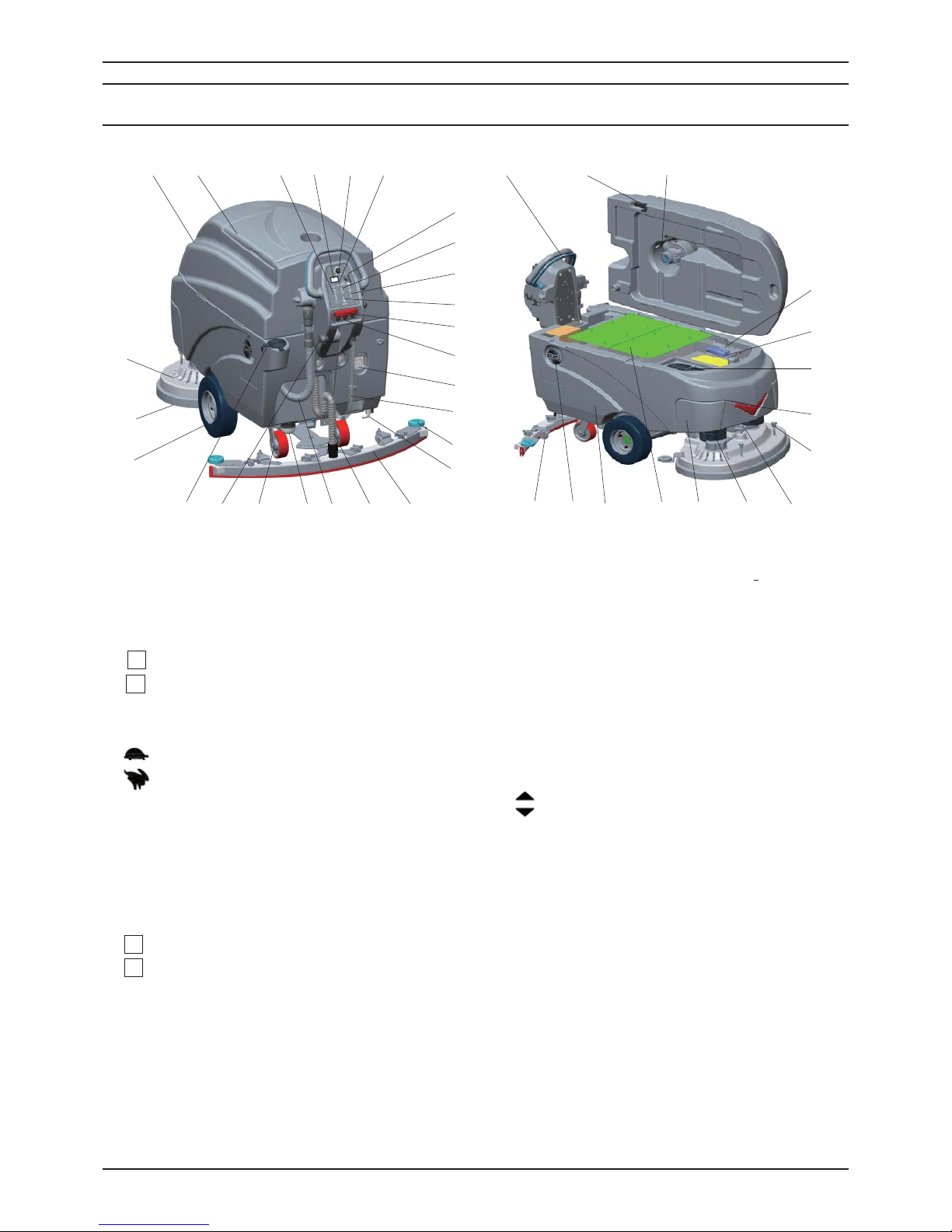
MACHINE COMPONENTS
1. Recovery Tank
2. Recovery Tank Cover
3. Brush Pressure Adjusting Buttons &
Indicator Light
Brush Pressure Increase Button
Brush Pressure Decrease Button
4. Hour Meter
5. Speed Control Knob
Slow Speed
Fast Speed
6. Battery Meter
7. Main Power Key Switch
8. 1-STEP Scrub Head Up/Down Switch &
Indicator Light
9. Solution Flow Control Buttons & Indicator
Light
Solution Flow Increase Button
Solution Flow Decrease Button
10. Vacuum Motor Switch & Indicator Light
11. Emergency Stop Button
12. Drive Motor Circuit Breaker
13. On-board Charger
14. Solution Tank Level / Drain Hose
15. Bumper Rollers
16. Ball Valve
17. Squeegee Assembly
18. Squeegee Vacuum Hose
19. Recovery Tank Drain Hose
20. Filter Assembly
21. Caster, 5 Inch
22. Squeegee Lift Lever
23. Hose Fill-port
24. Wheels,12 Inch
25. Scrub Head Skirt
26. Disk Scrub Head
27. Control Handle Start Bail
Direction Decal
28. Recovery Tank Support Stand
29. Vacuum Motor, 36VDC
30. Vacuum Motor Circuit Breaker
31. Connector,175A
32. Bucket Fill Port/ Clean-Out Port
33. Led Light
34. Brush & Pad Realease Plunger
35. Scrub Head Adjusting Bolt
36. Brush Motor,36VDC
37. Front Cover
38. Batteries
39. Solution Tank
40. Logo,ICE
41. Caster, 2 Inch, Squeegee
4
35
7
8
9
10
11
12
16
17
18
1920
22
23
25
41
+
-
2
1
15
40
38
37
36
+
-
35
27
6
13
14
21
26
24
28 29
30
31
32
33
34
39
Page 6
6
OPERATOR MANUAL
ICE i36BT
UNCRATING MACHINE
Be sure and check packing carton for any damage.
Immediately report any damage to carrier. Check
the contents of package to ensure that the
following items are included:
• Machine
• 6-6V Batteries
• Squeegee assembly
• 2-Pad Drivers
• 2-Brushes
INSTALLING BATTERIES
The batteries are already in the machine upon
delivery; However you will need to connect the
cables to the battery posts.
WARNING: Batteries emit hydrogen gas.
Explosion or fire can result from hydrogen
gas.Keep sparks and open flames away! Keep
battery compartment open when charging.
Recommended Battery spec:
6-6V, 260AH@20HR or 330AH@20HR deep cycle
batteries.
Max. batteries dimensions :
590mm (L) X 534mm (W) X 365mm (H)
1. Turn the main power key switch off.
2. Open recovery tank to gain access to battery
compartment.
3. Carefully place the batteries into the
compartment as shown in figure below. Place
the battery brace at the rear of the batteries.
DO NOT DROP BATTERIES INTO
COMPARTMENT!
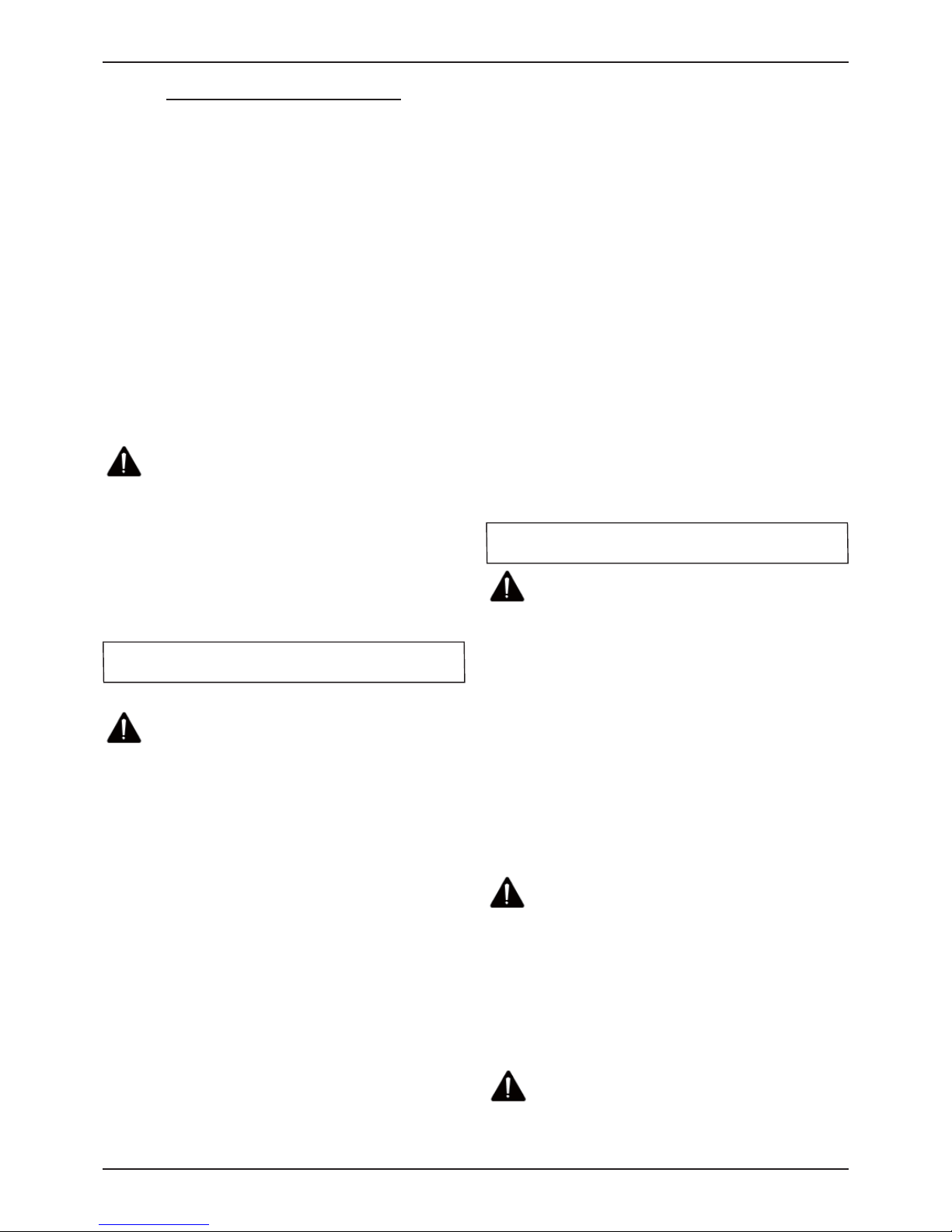
4. Connect battery cables to posts in numbered
order as shown in drawing below.
RED to POSITIVE and BLACK to NEGATIVE.
MACHINE SET UP
PRE-OPERATION CHECKS
1. Sweep or dust mop the surface to be cleaned.
2. Check battery meter to make sure batteries are
fully charged. (See BATTERY CHARGING)
3. Check that squeegee is properly installed.
4. Check that brushes / pads is properly installed.
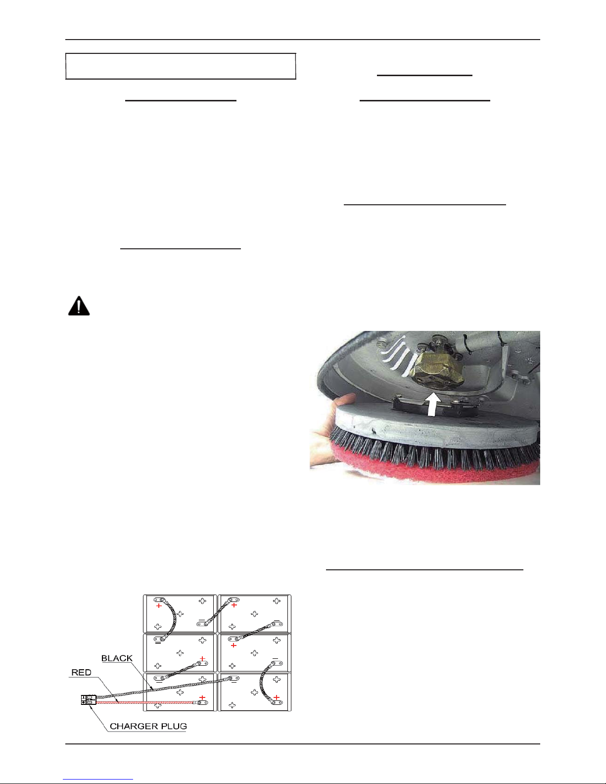
INSTALLING BRUSHES OR PADS
1. Turn off the 1-STEP Scrub head up/down switch
(see machine components, item #8) and Raise
the Scrub head off the floor, then stop machine
on the level surface, remove the key and ensure
the machine is turned off.
2. If using the Pad Driver, first attach the
appropriate pad to the pad driver surface.
3. Align the pad driver or brush under the motor
hub and push it upward to engage.
4. To remove the pad driver or brush, raise
the scrub head and push the pad release
plunger (see machine components, item #34)
downward.
MOUNTING THE SQUEEGEE ASSEMBLY
1. Lift the squeegee lift lever (see machine
components, item #22)to the upward position.
2. Mount the squeegee assembly to the squeegee
pivot bracket. make sure the knobs are
completely seated into the slots before securing
knobs.
3. Connect the vacuum hose to the squeegee
assembly. Loop the hose by using the hose clip
provided.
4. Check the squeegee blades for proper
adjustment.
MACHINE SET UP & INSTALLATION
Page 7
7
OPERATOR MANUAL
ICE i36BT
FILLING THE SOLUTION TANK
The machine is equipped with a hose fill-port (see
machine components, item #23) at the rear of
the machine, and a bucket fill-port (see machine
components, item #32)located under the recovery
tank. Before accessing the bucket fill-port make
sure that the recovery tank is empty.
Fill the solution tank to the "110L" level on the
solution tank sight gauge. When using the bucket
fill-port, stop filling when the level reaches the
bottom edge of the fill-port.
NOTE: When fi lling the solution tank with a
bucket, make sure that the bucket is clean. Do not
use the same bucket for fi lling and draining the
machine.
WARNING: Do not put any flammable
materials into solution tank. this can cause an
explosion or a fire. Only use recommended
cleaning chemicals. Contact your janitorial
supply distributor for recommendations on
proper chemicals.
WARNING: Do not operate machine
unless you have read and understand this
manual.
1. Turn the main power key switch(see machine
components, item #7) to the on (I) position.
2. Check the battery level meter (see machine
components, item #6), if the battery meter
is in the red, DO NOT continue to operate
the machine and recharge the batteries
immediately.
3. Turn on the 1-STEP scrub head up/dwon switch
(see machine components, #8) to lower the
scrub head to the floor, the 1-STEP switch
indicator is light.
4. Lower squeegee assembly to the floor by
lowering the squeegee lift lever(see machine
components, item #22).
5. Check the solution flow indicator (see machine
components, item #9), adjust the solution flow
control switch to a desired flow rate.
NOTE: Solution will not begin to fl ow until the
control handle bail is pulled.
6. Turn on the vacuum motor switch(see machine
components, item #10).
7. Pull the control handle bail (see machine
components, item #27) backwards to start
scrubbing .The machine will automatically
propel forward. To reverse the machine, simply
push the control handle bail forward.
NOTE:
Raise squeegee when reversing machine.
8. The scrubbing speed can be adjusted,
Adjust the speed control knob (see machine
components, item #5) to a desired speed.
NOTE: 45-60 meters (150-200 ft)per minute is
the recommended scrubbing speed.
simply press the pressure adjuting button to
increase (+) or decrease (-) the brush pressure
as needed.(see machine components, item #3)
10. To stop scrubbing, release the control handle
bail, turn off the 1-STPE switch to raise
the scrub head assembly, raise he squeegee
assembly.
WARNING: Fire Or Explosion Hazard. Do
Not Pick Up Flammable Materials Or Reactive
Metals.
1. Go slow on inclines and slippery surfaces. Do
not operate the machine on inclines that exceed
5% (3°).
2. Do not keep the machine in the same position
with pad / brush spinning, keep the machine
moving to prevent damage to floor finish.
3. If the squeegee assembly leaves streaks on the
floor, raise the squeegee off the floor and wipe
the blades down with a damp cloth. Pre-sweep
the area to prevent leaving streaks on the floor.
4. Pour a recommended defoamer into the
recovery tank if excessive foam appears.
WARNING: Do not allow foam to enter
the float shut-off screen, vacuum motor
damage will result. Foam will not activate the
float shut-off screen.
5. Occasionally check the battery level meter(see
machine components, item #6). when meter
is in the red, stop scrubbing and recharge the
batteries.
WARNING: When battery meter is in the
red, do not continue to operate the machine.
Battery damage may result.
MACHINE OPERATION
WHILE OPERATING MACHINE
Page 8

8
OPERATOR MANUAL
ICE i36BT
6. When the solution tank runs empty, press the
1-STEP switch raise the brush head. Keep the
squeegee down and continue to vacuum until all
the dirty water is picked up.
NOTE: Brush motors will not work when
the scrub head assembly raised.
NOTE: See TANK DRAINING section to learn
how to drain recovery and solution tanks.
CIRCUIT BREAKER / FUSES
The machine is equipped with 2 resettable circuit
breakers(see machine components, item #12,
item# 30) to protect the drive motor and the
vacuum motor from damage. If the circuit breakers
should trip, it can't be reset immediately. You must
first determine what caused the breaker to trip, and
allow the motor to cool down and then you can
manually reset the circuit breakers.
The machine is also equipped with a 50A current
transformer to protect the brush motors from
damage. When replacing a fuse never substitute a
higher Amps rated fuse than specified.
HOUR METER
The hour meter (see machine components, item
#4) records the number of total hours the brush
motor has been powered on. Use the hour meter
to determine when to perform recommended
maintenance procedures and to record service
history.
EMERGENCY STOP BUTTON/ BRAKE
The machine is equipped with an Electromagnetic
Brake Mechanism on the Transaxle. When in case
of Emergency, release the Control Handle bail(see
machine components, item #27) or strike the
Emergency stop button (see machine components,
item #11), the machine will be braked and then
stop. Reset the emergency stop button, turn on the
Main power key switch, and then pull the control
handle bail, the machine will be restart.
NOTE: The machine can not be moved unless the
Main Power Key Switch and the Control Handle
bail be turned on.
WARNING: Do Not Change the Default
Settings of the Electromagnetic Brake
Mechanism unless Authorized, otherwise it
may cause Machine Damage or Personal Injury.
Contact the Authorized Service center for
machine repairs.
1. Turn the machine off.
2. With the squeegee and scrub head in their "up"
position, transport machine to approved area for
draining tank(s).
DRAINING THE RECOVERY TANK
Any time scrubbing is completed, or when refilling
solution tank, the recovery tank should be drained
and cleaned.
WARNING: If the recovery tank is not
drained when the solution tank has been
refilled, foam or water may enter the filter
screen and cause damage to the vacuum
motor.
1. While holding the drain hose (see machine
components, item #19) upward, remove the cap
and lower hose to drain.
2. Open the recovery tank cover and rinse out the
tank. Use a rag to remove any excess dirt.
3. Clean the filter screen located in the recovery
tank .
DRAINING THE SOLUTION TANK
Any time scrubbing operation is completed, the
solution tank should be drained and cleaned.
1. Pull the solution tank level hose(see machine
components, item #14) off the hose fitting, this
will allow the solution to flow freely into a bucket
or floor drain.
2. Remove the cover of the filter assembly(see
machine components, item #20) to drain the
solution tank, check the filter screen and clean
up it if necessary.
3. Rinse the solution tank with clean water after
every use. This will help prevent chemical
buildup and clogging of the solution lines.
4. After rinsing out the tank, securely reconnect
the tank level hose to the hose fitting, replace
the filter assembly cover and be sure the
filter screen and the "O" ring is in the correct
position.
TANK DRAINING
Page 9
9
OPERATOR MANUAL
ICE i36BT
BATTERY CHARGING
WARNING: Fire Or Explosion Hazard.
Batteries Emit Hydrogen Gas. Keep Sparks and
Open Flame Away. Keep Battery Compartment
Propped Open When Charging.
NOTE: Use only apprved chargers with the
following specifi cations:
• Automatic shut off circuit
• Deep cycle charging
• Output current of 20-30 Amps
• Output voltage of 36 volts
ON-BOARD BATTERY CHARGER
As standard configuration, the machine is equiped
with the On-board battery charger (see machine
components, item #13). The settings of On-board
battery charger had been set for the recommended
batteries type.
WARNING: The On-board battery
charger setting's change are to be completed
by authorized service centers only. Failure
to properly set will result in the batteries or
charger damage.
1. Transport the machine to a well ventilated area.
2. Turn the machine off.
3. If charging wet (lead acid) batteries check the
fluid level before charging.
4. Prop up the recovery tank by the support
stand (see machine components, item #28) for
ventilation.
5. Connect the charger's AC power supply cord to
a properly grounded receptable.
6. The charger will automatically begin to charge,
once the charging cycle begins, the indicator
lights will progress from red, yellow to green.
when the green indicator light comes on, the
charging cycle is done. Unplug the charger
cord.
NOTE: The machine will can not operate when
charging.
OFF-BOARD BATTERY CHARGER (OPTION)
1. Place charger and machine in a well ventilated
area.
2. Turn the machine off.
3. If charging wet (lead acid) batteries check the
fluid level before charging.
4. Prop up the recovery tank by the support
stand (see machine components, item #28) for
ventilation.
5. Connect the charger's AC power supply cord to
a properly grounded receptable.
6. Connect the charger's DC cord into the
machine's battery receptacle at the rear of the
machine.
7. The charger will automatically begin to charge
and will autoatically shut off once the batteries
are fully charged.
8. Upon completion of charging, disconnect the
AC power supply cord first, and then disconnect
the charger from the machine.
WARNING: Before performing any
maintenance on the machine, be sure that
the power is turned off, or the batteries are
disconnected!
WARING: Repairs are to be completed
by Authorized service centers only. Any repairs
completed by unauthorized persons will avoid
the warrenty.
DAILY MAINTENANCE
1. Remove pad driver/ brush and clean with
approved cleaner.
2. Drain recovery and solution tanks completely
and rinse out with clean water. Visually check
the recovery tank for debris and clean out as
necessary.
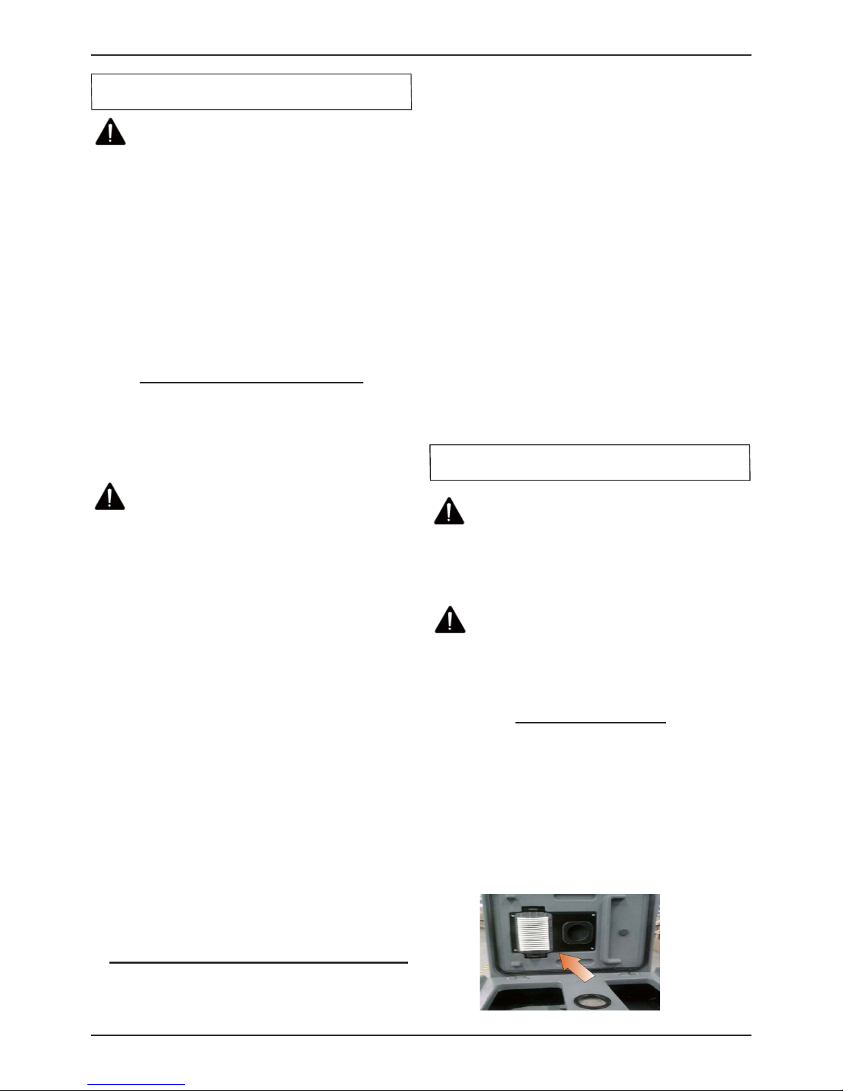
3. Open recovery tank cover,Remove the vacuum
fan filter and rinse it out with low pressure water,
if dirty.
PREVENTATIVE MAINTENANCE
Page 10
10
OPERATOR MANUAL
ICE i36BT
4. Raise the squeegee assembly off floor and wipe
it down with a damp towel. Be sure to store the
squeegee in the up position.
5.
Clean machine with an approved cleaner and a
damp towel.
6. Recharge the batteries.
7.Check the condition of the squeegee blade
wiping edge, rotate blade if worn.
MONTHLY MAINTENANCE
1. Clean the battery tops to prevent corrosion.
2. Check for loose battery cable connections.
3. Inspect and clean the recovery tank cover seal.
Replace it if damaged.
4. Lubricate all grease points and pivot points with
silicon spray and approved grease.
5. Check the machine for loose nuts and bolts.
6. Check the machine for leaks.
MOTOR MAINTENANCE
1. Contact your local Distributor for any motor
maintenance.
2. Motor should have the brushes checked every
250 hours. Brushes should be replaced when
they are worn to a length of 10 mm or less.
BATTERY MAINTENANCE
WARNING: Batteries emit hydrogen gas
and an explosion o fire can result. Keep sparks
and fire away from batteries at all times.
WARNING: Whenever serviving batteries,
be sure to wear protective gloves. Avoid
contact with battery acid at all times.
NOTE: For the best machine performance, keep
batteries charged at all times. Do not let them sit in
a discharged condition.
1. Always follow the battery charging directions as
outlined in the BATTERY CHARGING section of
this manual.
2. Keep battery tops and terminals free from
corrosion. A strong solution of baking soda
and water is the best way to keep the batteries
corrosion free. DO NOT ALLOW THE BAKING
SODA / WATER SOLUTION TO ENTER THE
BATTERY CELLS.
3. Use a wire brush with the baking soda solution
to properly clean the battery posts and
connctions.
4. Check battery connections for wear and loose
terminals. replace if necessary.
MACHINE STORAGE
1. Always store the machine indoors.
2. Always store the machine in a dry area.
3. Always store the machine in its upright position.
4. Always store the machine with the pad driver/
brush raised off the floor.
5. Always store the machine with the squeegee
assembly raised off the floor.
6. If storing in an area which may reach freezing
temperatures, be sure to drain all fluids from the
machine prior to storage. Any damage caused
by freezing temperatures will not be covered by
the warranty.
7. Drain the recovery tank.
8. Drain the solution tank of all fluid.
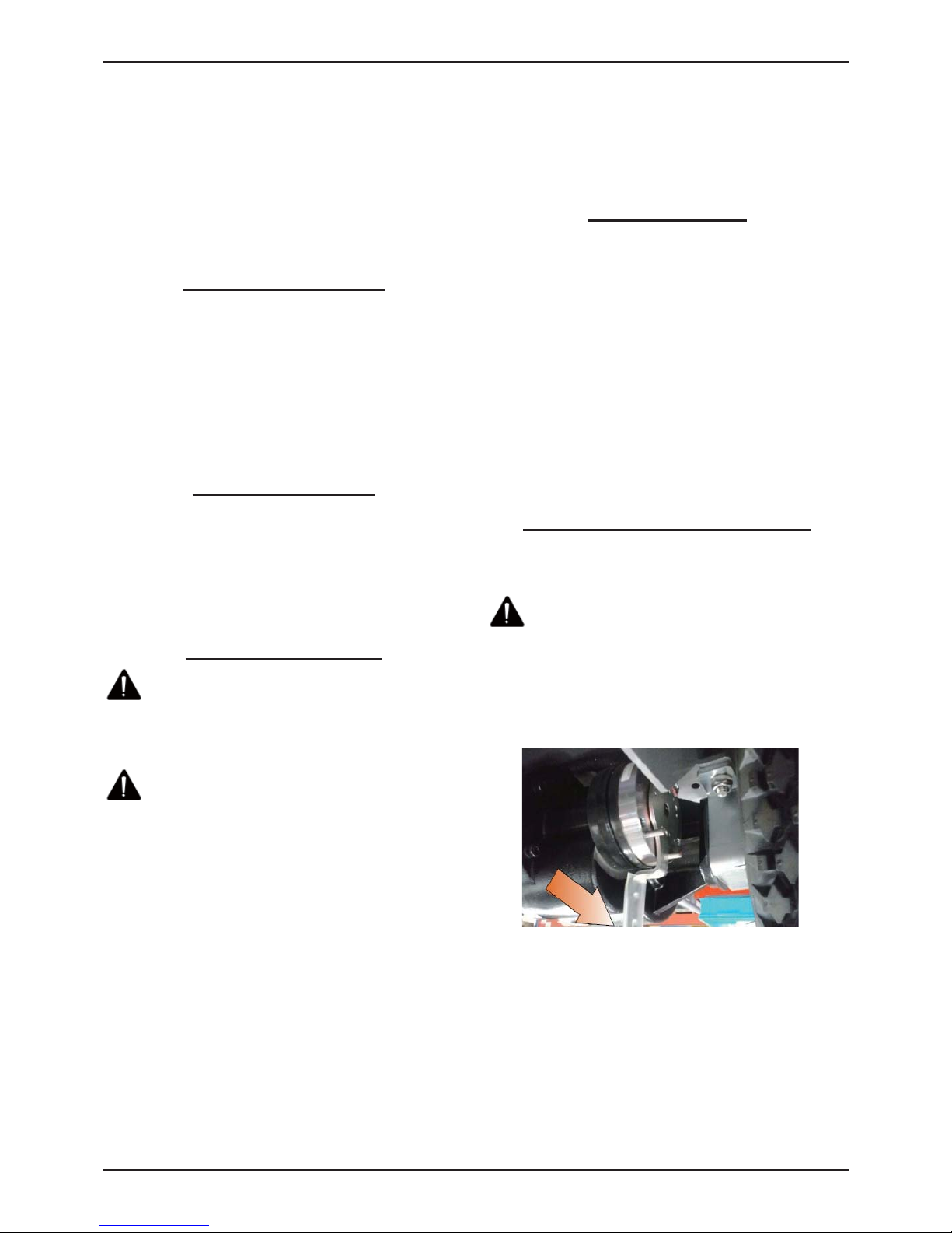
PUSHING OR TOWING THE MACHINE
If the machine becomes disabled, it can be pushed
from the front or rear, but only tow it from the rear.
WARNING: When servicing machine, do
not push or tow the machine on inclines with
the brake disabled.
Before attempting to push or tow the
machine,disengage the brake as described
below.To disengage the brake,you can turn the
electronic brake lever to the other side.
Page 11

11
OPERATOR MANUAL
ICE i36BT
PROBLEM CAUSE SOLUTION
Machine will not
operate
Control handle bail not pulled Pull control handle bail
Batteries need to be charged Charge batteries
Bad battery(s) Replace battery(s)
Loose battery cable Tighten loose cable
Emergency stop button activated Reset Emergency stop botton
Main PCB fuse blown Contact ICE service center
Faulty key switch Contact ICE service center
Brush motor will
not operate
1-STEP scrub head up/down switch is off Turn on the 1-STEP switch
Battery meter lockout activated Recharge batteries
Brush motor fuse blown Replace 50A current transformer
Brush motors over load Turn on / off the 1-STEP switch
Faulty control handle bail switch Contact ICE service center
Faulty brush motor or wiring Contact ICE service center
Worn Motor carbon brushes Contact ICE service center
Bad solenoid Contact ICE service center
Machine does
not propel
The Main Power Key Switch be Turned off,
the Control handle bail not pulled
Turn on the Key switch, Pull the control
handle bail
Tripped drive motor circuit breaker Reset drive motor circuit breaker button
Faulty transaxle motor or wiring Contact ICE service center
Worn Motor carbon brushes Contact ICE service center
Vacuum motor
will not operate
Recovery tank is full Drain recovery tank
Tripped vacuum motor circuit breaker Reset vacuum circuit breaker button
Faulty vacuum motor or wiring Contact ICE service center
Worn Motor carbon brushes Contact ICE service center
Little or no
solution flow
Ball valve set too low or shut off Turn on the ball valve
Solution flow control knob set too low or
shut off
Adjust solution control flow knob
Clogged solution tank filter or solution
hose
Clean solution tank filter or flush out
solution hose
Clogged solution Solenoid valve Remove valve and clean
Poor water pick
up
Recovery tank is full Drain recovery tank
Loose drain hose cap Tighten cap
Clogged filter located in recovery
tank cover
Clean filter
Clogged squeegee assembly Clean squeegee assembly
Worn squeegee blades Replace or rotate squeegee blades
Incorrect squeegee blade def ection Adjust squeegee blade height
Loose vacuum hose connections Secure hose connections
Clogged vacuum hose Remove clogged debris
Damaged vacuum hose Replace vacuum hose
Recovery tank cover not in place Properly position cover
Damaged recovery tank cover seal Replace seal
Faulty vacuum motor Contact ICE service center
Low battery charge Recharge batteries
Short run time
Low battery charge Fully recharge batteries
Defective batteries Replace batteries
Batteries need maintenance See BATTERY MAINTENANCE
Faulty battery charger Repair or replace battery charger
Down pressure lever is set for extra scrub
head pressure
Lower down pressure lever
BASIC TROUBLESHOOTING
Page 12

12
OPERATOR MANUAL
ICE i36BT
TECHNICAL SPECIFICATIONS
MODEL i36BT
DIMENSIONS L X W X H 1650 X 865 X 1130 mm
WEIGHT 170 Kg
WEIGHT WITH BATTERIES 440 Kg
SOLUTION TANK CAPACITY 110 L / 29 Gal
RECOVERY TANK CAPACITY 120 L / 31.5 Gal
SQUEEGEE WIDTH 1185 mm / 46.5 in
CLEANING PATH WIDTH 800mm / 32 in
PRODUCTIVITY RATE 3250 m
2
h
DRIVE SYSTEM Transaxle, 36VDC, 350W
TRAVEL SPEED, MAXIMUM Cleaning: 65m/Min Transporting: 72 m/Min
MINIMUM ALSLE TURN 1600mm
PAD/BRUSH PRESSURE 40kg / 65kg / 90kg
SOLUTION FLOW RATE 0 ~ 3200ml/Min
BRUSH MOTOR(S) 650WX2,36VDC
VACUUM MOTOR 600W,36VDC
WATER LIFT - AIR FLOW 65 in
BATTERIES 6 - 6V, 260AH or 305AH @ 20 hr
RUN TIME PER CHARGE
4 or 4.5 Hours
VOLTAGE DC
36V
DECIBEL RATING AT
OPERATOR'S EAR, INDOORS
68 dB(A)
GRADE LEVEL, MAX 10% (6°)
Page 13

Page 14

DIA
NO
PART
NUMBER
NO
REQ'D
1 8230103
1
2 8230201
1
3 8011005
1
4 8230209
1
5 8230208
1
6 8230204
1
7 1321213
2
8 1421510
9
9 8113007
1
10 8131003
1
11 8310238
1
12 1221512
3
13 8113009
1
14 8230102
1
15 8131010
1
16 1962050
1
17 8230205
1
18 1421816
4
19 1021820
2
HEX BOLT,M8 X 20
RECOVERY TANK COVER
STRIP
CAP
RECOVERY TANK
DRAIN HOSE
CLAMP
CABLE
FLAT WASHER,M8 X 16 X 1.6
SEAL
SENSOR, LEVEL, LIQUID,
SCREW,M5X12
CLAMP
RECOVERY TANK GROUP
DESCRIPTION
CAP
GASKET
GASKET, SCREEN
SCREEN
SELF-TAPPING SCREW,ST4.2 X 13
WASHER,M5 X 10 X 1
20 8111300
2
21 1421618
8
22 1021616
8
23 8112005
1
24 1121605
3
25 8210209
3
26 8230200
1
27 1421612
5
28 1123608
3
29 1914300
1
30 8132007
1
31 8230126
1
32 4010316
1
33 8111022
1
34 8111008
1
35 8111007
1
36 8115404
1
37 1021830
1
38 8230210
1
39 8310237
1
40 8310230
1
41 8111016
2
42 1221510
7
43 8230207
1
STUD,M6 X 110
3 STAGE VACUUM MOTOR,36VDC,640W,KIT
FLAT WASHER,M6 X 12 X 1.6
LOCK NUT,M6
TIE, NYLON, 5 X 300
LABEL, BATTERY INSTALLATION
ICE LOGO
PLATE
GASKET,FILTER
PLATE
SCREW,M5 X 10
WARNING LABEL
BRACKET
RECOVERY TANK SUPPORT
SLEEVE, P/M
HEX BOLT,M8 X 30
BRACKET,FILTER
FILTER,DUST
HINGE ASSEMBLY
FLAT WASHER,M 6 X 18 X 1.6
HEX BOLT,M6 X 16
GASKET, VACUUM MOTOR
HEX NUT,M6
MUFFLER, VACUUM MOTOR
14ICE i36BT
Page 15

Page 16

DIA
NO
PART
NUMBER
NO
REQ'D
1 6210131
6
2 1421510
20
3 1221512
9
4 1123507
6
5 8230114
1
6 1421612
14
7 1021616
12
8 1221525
4
9 8230117-US
1
10 8230127
1
11 8210112
2
12 1222641
2
13 1321213
2
HOOK, CORD
SCREW,M6 X 40
SELF-TAPPING SCREW,ST4.2 X 13
CAP
,
SOLUTION FILL
PLATE
SOLUTION TANK GROUP
DESCRIPTION
NYLON, CLAMP
FLAT WASHER,M5 X 10 X 1
SCREW,M5 X 12
LOCK NUT,M5
BRACKET, ON BOARD CHARGER
FLAT WASHER,M6 X 12 X 1.6
HEX BOLT,M6 X 16
SCREW,M5 X 25
ON BOARD BATTERY CHARGER,36VDC,KIT
14
8210113
1
15 4010316
2
16 8230134
1
17 1962025
1
18 8230101
1
19 8114751
12
20 8230705
5
21 8113013
4
8210105
6
8230120
6
23 8230121
1
24 8230104
1
25 1321110
3
26 1421409
3
27 8230750
1
28 8133601
1
29 1221520
3
30 8133602
1
31 8210518
2
22
KNOB, M8
SELF-TAPPING SCREW,ST3.5 X 10
FLAT WASHER,M4 X 9 X 0.8
LED LIGHT,36V,KIT
LED LIGHT MOUNTING BASE
SCREW,M5 X 20
LED LIGHT COVER
SPACER, BATTERY
BATTERY, 260AH @ 20Hr
BATTERY, 305AH @ 20Hr (OPTIONAL)
BATTERY TRAY
COVER, FRONT
BATTERY CONNECT CABLE, BLACK
,
ICE LOGO
CLEAN TUBING
CLAMP,16 - 25mm
SOLUTION TANK
JACKET, BATTERY TERMINAL, BLACK
32 1535830
2
16ICE i36BT
SET SCREW,M8 X 30
Page 17

DIA
NO
PART
NUMBER
NO
REQ'D
SOLUTION TANK GROUP
DESCRIPTION
33 1421618
6
34 8113112
2
35 8113030
1
36 8113002
1
37 8113007
1
38 1221520
2
39 8230711
1
40 8114703
1
41 8230708
1
42 1123608
4
43 8230128
1
44 1422616
6
45 8230707
1
COVER
STRAP
BUSHING
SEAL
PLAIN WASHER ,M6 X 18 X 1.6,SS
SCREW,M5 X 20
CURRENT TRANSFORMER, 50A
CIRCUIT BREAKER, 35A
SOLENOID SWITCH,36VDC
LOCK NUT,M6
BRACKET, SOLENOID SWITCH
LOCK WASHER, M6
KIT,BATTERY CONNECT CABLE
CONNECTOR
,
SB175-GRE
Y
46
8230714
2
47 1521635
2
48 8230706
1
49 1021610
2
50 8144024
2
51 8230702
1
52 8114705
2
,
SCREW, HEX SOCKET, M6 X 35
KIT,BATTERY CONNECT CABLE
HEX BOLT,M6 X 10
LABEL,CIRCUIT BREAKER
SOLENOID SWITCH,36VDC
STAND-OFF, M6, RED
17ICE i36BT
Page 18

Page 19

DIA
NO
PART
NUMBER
NO
REQ'D
1 8211505
1
2 1421132
1
3 8210508
1
4 8135001
2
5 8211501
1
6 1123810
7
7 8211507
1
8 8211506
1
9 1123608
5
10 1421618
2
11 8211503
1
12 8114511
1
13 8211504
4
14 1121807
1
15 1421824
4
BRACKET, SQGE MNTG
BALL JOINT,M6
SHOULDER BOLT,M12 X 7 X M8
FLAT WASHER,M8 X 24 X 2
NUT,M8
FLAT WASHER,M6 X 18 X 1.6
FRAME & DRIVE GROUP
DESCRIPTION
SHOULDER BOLT,M12 X 30 X M10
FLAT WASHER,M12 X 32 X 1.5
SPIRNG
PLASTIC THRUST WASHER,M12 X 30 X 1.5
BRACKET, SQGE LIFT
LOCK NUT,M8
KNOB, M8
PIN
LOCK NUT,M6
16
8211508
1
17 8211502
1
18 1421020
13
19 1021030
8
20 1123012
13
21 1124111
6
22 1123111
6
23 1421120
6
8230129
2
8230116
2
25 8230118
2
8230810
1
8230811
1
27 8230119
2
28 1022809
1
29 1021820
5
30 1422821
5
31 1421828
5
32 8210115
2
33 8210116
2
34 1021830
5
26
24
WHEEL,12", FOAM FILL
LOCK WASHER,M8
FLAT WASHER,M8 X 28 X 2
ARM, SCRUB HEAD LIFTING
BUSHING
HEX BOLT,M8 X 30
HEX BOLT,M8 X 20
HEX BOLT,M8 X 90
TRANSAXLE, 36VDC,KIT
5",CASTER
ELECTRIC BRAKE KIT
HEX BOLT,M10 X 30
LOCK NUT,M10
FLAT WASHER,M10 X 20 X 2
BUSHING
BRACKET, SWING
NUT,CAP
LOCK NUT,7/16"- 20UNF
FLAT WASHER,M12.1 X 20 X 2
WHEEL,12", PNEUMATIC (OPTIONAL)
BRACKET, TRANSAXLE MOUNTING
35
8230105
1
36 1021025
4
19ICE i36BT
FRAME
HEX BOLT,M10 X 25
Page 20

Page 21

DIA
NO
PART
NUMBER
NO
REQ'D
1 8210830
1
2 8210807
2
3 8210309
2
4 1421816
14
5 1021825
11
6 8210806
1
7 8210820
1
8 1123810
10
9 8230300
2
10 1655025
2
11 8210808
2
12 8210809
2
13 8230301
1
14 1421612
8
15 1422616
8
16 1021620
8
17 8210805
2
18 1421828
2
SCRUB HEAD GROUP
DESCRIPTION
FLAT WASHER,M6 X 12 X 1.6
HEX BOLT,M8 X 25
BRACKET, ACTUATOR MNTG
BRACKET, SCRUB HEAD LIFT, LEFT
LOCK NUT,M8
BRUSH MOTOR, 36VDC, 630W,KIT
KEY, 5 X 5 X 25
KNOB, M10
SPRING
HOUSING, SCRUB HEAD,i36BT
LOCK WASHER, M6
HEX BOLT,M6 X 20
HUB, BRUSH DRIVE
FLAT WASHER,M8 X 28 X 3.0
BRACKET, SCRUB HEAD LIFT, RIGHT
PIN
PIN, COTTER
FLAT WASHER,M8 X 16 X 1.6
19 1422821
2
20 8218050
2
21 1221635
12
22 1221640
4
23 1421618
4
24 8210861
4
25 8210862
4
26 9000004
4
27 9050016
2
28 1321325
6
29 9000003
2
30 8116040
6
31 9040016
2
32 8210804
4
33 1022090
2
34 1111215
1
35 8210811
1
36 8210810
1
37 1421824
2
38 8115404
1
39 8116009
1
40 1021830
1
FLAT WASHER,M8 X 24 X 2
SLEEVE, P/M
PROTECTIVE WHEEL
HEX BOLT,M8 X 30
HEX NUT, M16
AJUSTMENT STUD, M16
BRACKET, ROLLER MNTG
SPRING, G-400S
CLUTCH, G-400S
LOCK WASHER,M8
BUMPER, SCRUB HEAD
HEX BOLT,M10 X 90
BRUSH ASSEMBLY, 16 INCH
SELF-TAPPING SCREW,ST5 X 25
CENTER LOCK, #3
SPACER, 6.5 X 14.5 X 7.0
PAD DRIVER, 16 INCH
SPACER
SCREW, M6 X 35
SCREW, M6 X 40
FLAT WASHER,M6 X 18 X 1.6
RETAINER BAR
21ICE i36BT
Page 22

Page 23

DIA
NO
PART
NUMBER
NO
REQ'D
1 1123810
6
2 1421824
10
3 8210306
1
4 1021825
2
5 1422821
4
6 1021820
2
7 8210311
2
8 8210312
2
9 8210314
1
10 8210310
1
11 8210313
1
12 1022800
1
13 8210316
1
14 1123008
2
15 1022811
1
GUIDE, ROLLER
SCRUB HEAD LIFT GROUP
DESCRIPTION
LOCK NUT,M8
FLAT WASHER,M8 X 24 X 2
BRACKET, GUIDE MNTG
HEX BOLT,M8 X 25
LOCK WASHER,M8
HEX BOLT,M8 X 20
SPRING
WASHER, PM
SHAFT
ROLLER
HEX BOLT,M8 X 100
BRACKET, SCRUB LIFT
LOCK NUT,3/8
HEX BOLT,M8 X 110
16 8210319
2
17 8210317
1
18 1421132
4
19 8210322
1
20 8210309
2
21 8210318
2
22 8230311
2
23 8210321
2
24 8230302
1
25 8210301
1
26 8210303
1
27 1421612
4
28 1422616
4
29 1021616
4
SLEEVE
SPRING
BRACKET, SPRING
FLAT WASHER,M 12 X 32 X 1.5
PIN
PIN, COTTER
SPRING
BOLT, SHOULDER, 3/8
ACTUATOR, 36VDC
PIN
BRACKET, ACTUATOR MNTG
FLAT WASHER,M6 X 12 X 1.6
LOCK WASHER,M6
HEX BOLT,M6 X 16
23ICE i36BT
Page 24

Page 25

DIA
NO
PART
NUMBER
NO
REQ'D
1
8118300
1
2
8118003
4
3
1021835
2
4
1421824
2
5
8116009
2
6
8115404
2
7
1421816
6
8
1021616
8
9
1421618
8
10
8210515
2
11
8230501
1
12
1123810
2
13
1221575
1
14
8210525
1
SQUEEGEE HOUSING
LOCK NUT,M8
SCREW,M5 X 75
SHORT CLAMP ASSEBLY
BRACKET, ROLLER MNTG
SQUEEGEE GROUP
DESCRIPTION
RIGHT BRACKET
STAR KNOB,M8
HEX BOLT,M8 X 35
FLAT WASHER,M8 X 24 X 2.0
PROTECTIVE W HEEL
BEARING, JOURNAL
FLAT WASHER,M8 X 16 X1 .6
HEX BOLT,M6 X 16
FLAT WASHER,M6 X 18 X 1.6
15
1123507
1
8210520
1
8211520
1
17
1022845
1
18
8210527
1
8230504
1
8230507
1
20
8230502
1
8230503
1
8230506
1
22
8118400
2
23
1121008
2
24
8118200
1
25
8230500
1
26
8118109
1
27
8118006
1
28
1962050
1
16
19
21
CLAMP ASSEMBLY, SQUEEGEE
LEFT BRACKET
SQUEEGEE ASSEMBLY
HOLDER VACUUM HOSE
VACUUM HOSE
CLAMP ASSEMBLY, SQUEEGEE WITHOUT W HEEL(OPTIONAL)
HEX BOLT,M8 X 45
WHEEL, 2 INCH
SQUEEGEE BLADE, REAR, LINATEX
SQUEEGEE BLADE, REAR, PU (OPTIONAL)
CLAMP
RETAINER,SQUEEGEE
SQUEEGEE BLADE, FRONT, LINATEX
SQUEEGEE BLADE, FRONT, PU (OPTIONAL)
CASTER, 2 INCH
HEX NUT,M10
LOCK NUT,M5
25ICE i36BT
Page 26

Page 27

DIA
NO
PART
NUMBER
NO
REQ'D
1
8119005
1
2
8119007
1
3
8119006
4
4
8230304
1
5
8119100
1
6
8119101
1
8119103
1
8119105
1
8
1622063
1
9
8119102
1
10
1421510
2
11
1221512
2
12
8230305
1
13
8230309
1
14
8230306
1
FILTER ASSEBLY
BASE, FILTER ASSEMBLY
SCREEN, FILTER, 70 MESH
SCREEN, FILTER, 40 MESH (OPTIONAL)
"O" RING
CAP, FILTER ASSEMBLY
FLAT WASHER,M5 X 10 X 1
SCREW ,M5 X 12
TUBING,ID=12 X 560MM
ELBOW, TUBING BARB
TUBING,ID=16 X 120MM
TUBING,ID=12 X 365MM
7
SOLUTION GROUP
DESCRIPTION
BALL VALVE, G1/2
ELBOW,G1/2
CLAMP
15
1962025
4
16
1221512
2
17
1422513
2
18
1421512
2
19
8230122
1
20
1914300
5
21
8230307
1
22
8310903
2
23
8230308
1
24
1962016
2
TUBING,ID=16 X 300MM
TUBING,ID=12 X 175MM
FITTING, PLASTIC, TEE
CLAMP, 10-16mm
SCREW ,M5 X 12
LOCK WASHER,M5
FLAT WASHER,M5 X 10 X 1
SOLENOID VALVE,36VDC
TIE, NYLON, 5X300
CLAMP, 16-25
mm
27
ICE i36BT
Page 28

Page 29

DIA
NO
PART
NUMBER
NO
REQ'D
1 8134001
1
2 1421307
5
3 1221306
5
4 8230709
1
5 8134015
1
6 1123305
6
7 8114710
1
8 8114709
1
9 8124717
1
10 8124718
1
11 8210410
1
12 8230701
1
13 1221512
12
14 8230713
1
15 1021616
5
LIGHT BELT,36V
HEX BOLT,M6 X 16
POTENTIOMETER
KNOB, POTENTIOMETER
CONTROL PANEL
CONTROL PANEL DECAL, i36BT
SCREW,M5 X 12
PCB ASSEMBLY,36VDC
GASLET
LOCK NUT,M3
TIMER
KEY SWITCH
CONTROL CONSOLE GROUP
DESCRIPTION
CONTROL CONSOLE HOUSING
FLAT WASHER,M3 X 7X 0.5
SCREW,M3X6
16 1421618
9
17 8124007
1
18 8210414
2
19 8124008
2
20 8144030
1
21 8114703
1
22 8124715
1
23 1421409
4
24 1221421
2
25 8114005
1
26 1421510
5
27 1021630
1
28 8014101
1
29 1021512
2
30 8134013
1
31 1421515
1
32 1021620
2
33 1121605
2
PLAIN WASHER ,M6 X18 X 1.6,SS
BUTTON,EMERGENCY STOP
CAP
SPRING
BASE, CIRCUIT BREAKERS MNTG
CIRCUIT BREAKER, 35A
EMERGENCY STOP SWITCH
CABLE, SQGE LIFT
CONNECTOR
FLAT WASHER,M5 X 10 X 1.0
HEX HEAD BOLT,M6 X 30,SS
LIFTING ROPE SPACER
FLAT WASHER,M4 X 9 X 0.8
SCREW,M4 X 20
HEX HEAD BOLT,M5 X 12,SS
FLAT WASHER,M5 X 15 X 1.0
HEX HEAD BOLT, M6 X 20
HEX NUT,M6
29ICE i36BT
Page 30

DIA
NO
PART
NUMBER
NO
REQ'D
CONTROL CONSOLE GROUP
DESCRIPTION
34 8014012
1
35 1123608
8
36 8134501
1
37 8134508
1
38 1421132
2
39 8014010
1
40 8113104
1
41 1021840
2
42 1422821
6
43 1421828
2
44 6210111
1
45 1221516
2
46 8124743
1
47 8114712
1
48 1434300
4
BAFFLE
LOCK NUT,M6
BRACKET
SLEEVE
FLAT WASHER,M12 X 32 X 1.5
SQUEEGEE LIFTING HANDLE
BALL KNOB,M8
HEX BOLT,M 8X 40
LOCK WASHER,M8
FLAT WASHER,M8 X 28 X 3
CLAMP, DRAIN HOSE
PH SCREW,M5X16,SS
MICRO SWITCH
MICRO SWITCH
LOCK WASHER, TOOTH, M3
49 1021320
4
50 8134022
1
51 8114402
1
52 1521616
2
53 8230710-US
1
54 8114300
1
55 1534608
4
56 1535630
1
57 8114306
1
58 8114101
1
59 8134300
1
60 1123507
3
61 8230704
1
62 8134021
1
63 1421824
6
64 1021820
6
65 1021535
2
66 8114707
1
RELAY
SCREW, M5 X 35
SCREW,M3 X 20
BRACKET,SWITCH
BRACKET, SPRING
REAR PLATE, CONTROL CONSOLE
FLAT WASHER,M8 X 24 X 2
HEX BOLT,M8 X 20
SPRING
SHAFT
LEVER, BAIL
LOCK NUT,M5
SPEED CONTROL BOARD,i36BT
SCREW,M6X16, HEX SCOKET
RESISTANCE,5W,300Ω,KIT
ACTUATOR
SET SCREW,M6 X 8
SET SCREW,M6 X 30
30ICE i36BT
Page 31

DIA
NO
PART
NUMBER
NO
REQ'D
1
8230129
2
2
8116009
3
3
8230119
2
4
8210513
1
5
8210514
1
6
9050016
2
7
9040016
2
16" BRUSH
16" PAD HOLDER
WAER & TEAR PARTS LIST
DESCRIPTION
WHEEL, 12 INCH
PROTECTIVE W HEEL
SQUEEGEE BLADE, FRONT, LINATEX
SQUEEGEE BLADE, REAR, LINATEX
CASTER, 5 INCH
ICE i36BT
31
Page 32

 Loading...