

Page 1
Operator & Parts Manual
Automatic Scrubber
www.icecompanies.com
www.icerental.com
INTELLIGENT CLEANING EQUIPMENT
8210080
REV.03 (03-2017)
i28BTL
i32BTL
Page 2
2
ICE i28BTL / i32BTL
OPERATOR MANUAL
HOW TO ORDER PARTS
Only use ICE Company supplied or equivalent parts. Parts and supplies may be ordered
online,by phone, by fax or by mail.
1. Identify the machine model.
2. Identify the machine serial number from the data label.
3. Ensure the proper serial number is used from the parts list.
4. Identify the part number and quantity.
Do not order by page or reference numbers.
5. Provide your name, company name, customer ID number,billing and shipping address,
phone number and purchase order number.
Please ll out at time of installation for future reference.
Model No.
Serial No.
Machine Options
Sales Rep.
Sales Rep. Phone No.
Customer ID Number
Installation Date
READ OPERATOR MANUAL CAREFULLY!
ICE Company Limited
XiangShi Road LiaoBu DongGuan GuangDong China
Tel: 0769 - 81869000
Fax:0769 - 81863000
Specifications and parts are subject to change without notice.
IMPORTANT: To ensure full warranty protection, please ll out & return
your warranty card.
PROTECT THE ENVIRONMENT
Please dispose of packaging materials,old machine components
such as batteries, hazardous uids, including antifreeze and oil, in an
environmentally safe way according to local waste disposal regulations.
Always remember to recycle.
Page 3

3
ICE i28BTL / i32BTL
OPERATOR MANUAL
SAFETY PRECAUTIONS......................................................................................................4
MACHINE COMPONENTS...................................................................................................5
PANEL COMPONENTS...................................................................................................6
i-synergy
TM
INTRDUCTION................................................................................................7
MACHINE SETUP & INSTALLATION....................................................................................7
MACHINE OPERATION.................................................................................................8
WHILE OPERATING MACHINE..........................................................................................8
TANK DRAINING..................................................................................................................9
BATTERY CHARGING........................................................................................................10
PREVENTATIVE MAINTENANCE......................................................................................10
FAULT CODE & SOLUTION................................................................................................11
BASIC TROUBLESHOOTING............................................................................................12
TECHNICAL SPECIFICATION............................................................................................13
PARTS LIST..............................................................................................................14-35
WEAR AND TEAR PARTS.................................................................................................36
WIRING DIAGRAM.............................................................................................................37
TABLE OF CONTENTS
Page 4
4
ICE i28BTL / i32BTL
OPERATOR MANUAL
SAFETY PRECAUTIONS
This machine is intended for commercial use. It
is designed exclusively to scrub hard oors in an
indoor environment and is not constructed for any
other use. Only use recommended accessories.
All operators shall read, understand and
exercise the following safety precautions:
1. Do not operate machine:
- Unless trained and authorized.
- Unless you have read and understand the
operators manual.
- In ammable or explosive areas.
- If not in proper operating condition.
- In outdoors areas.
2. Before starting machine:
- Make sure all safety devices are in place
and operate properly.
3. When using machine:
- Go slow on inclines and slippery
surfaces.
- Follow all safety guidelines.
- Be very careful when using the machine in
reverse.
- Reduce speed when turning.
- Report and x any damage to machine prior
to operating it.
- Never allow children to play on or
around.
- Do not operate on inclines that exceed 5%
(3°).
4. Before leaving or servicing machine:
- Stop on level surface.
- Turn off machine.
5. When servicing machine:
- Read operators manual thoroughly prior to
operating or servicing this machine.
- Use manufacturer supplied or approved
replacement parts.
- Secure machine with wheel blocks prior to
jacking the machine up.
- Use approved jack or hoist to safely elevate
the machine.
- Disconnect batteries prior to working on
machine.
- Avoid moving parts. Do not wear loose tting
clothing while servicing machine.
WARNING: Fire or Explosion Hazard.
Keep sparks and open ames away! Keep
battery compartment open when charging.
WARNING: Flammable materials can
cause an explosion or re. Do not use
ammable materials in tanks.
WARNING: Flammable materials or
reactive metals can cause explosion or re.
Do not pick up.
Page 5
5
ICE i28BTL / i32BTL
OPERATOR MANUAL
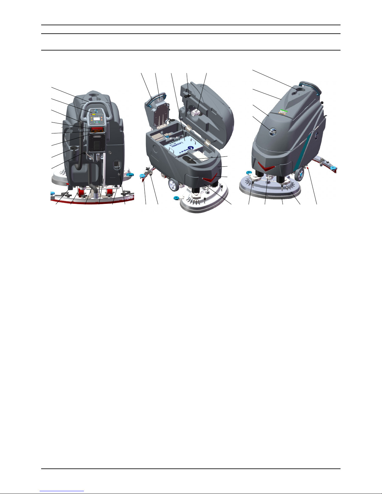
MACHINE COMPONENTS
1. Control handle
2. Control panel (See penal components)
3. Recovery tank drain hose
4. Emergency stop button
5. Circuit breaker, Controller
6. Circuit breaker, Brake
7. Hose ll port
8. Squeegee lift lever
9. Wheels, 8 Inch
10. Filter assembly
11. Vacuum hose
12. Solution tank level / Drain hose
13. Ball valve
14. On-board battery charger
15. Squeegee assembly
16. Caster, 2 inch, Squeegee adjustment
17. Control handle start bail
18. i-synergy
TM
, ID card scanning area
19. Lithium-ion batteries
20. Recovery tank support stand
21. Vacuum motor, 24VDC
22. Cup holder
23. Recovery tank cover
24. Recovery tank
25. ICE logo
26. Bucket ll port/ Clean-out port
27. Solution tank
28. LED light
29. Front cover
30. Brush & Pad realease plunger
31. Scrub head adjusting bolt
32. Scrub head skirt
33. Scrub head assembly
34. Parking brake (Option)
17
1514
13
1211109
5
4
3
19 20 21
23
24
25
27
29
22
28
2
1
16
30
31 32
332634
6
7
8
18
Page 6
6
ICE i28BTL / i32BTL
OPERATOR MANUAL
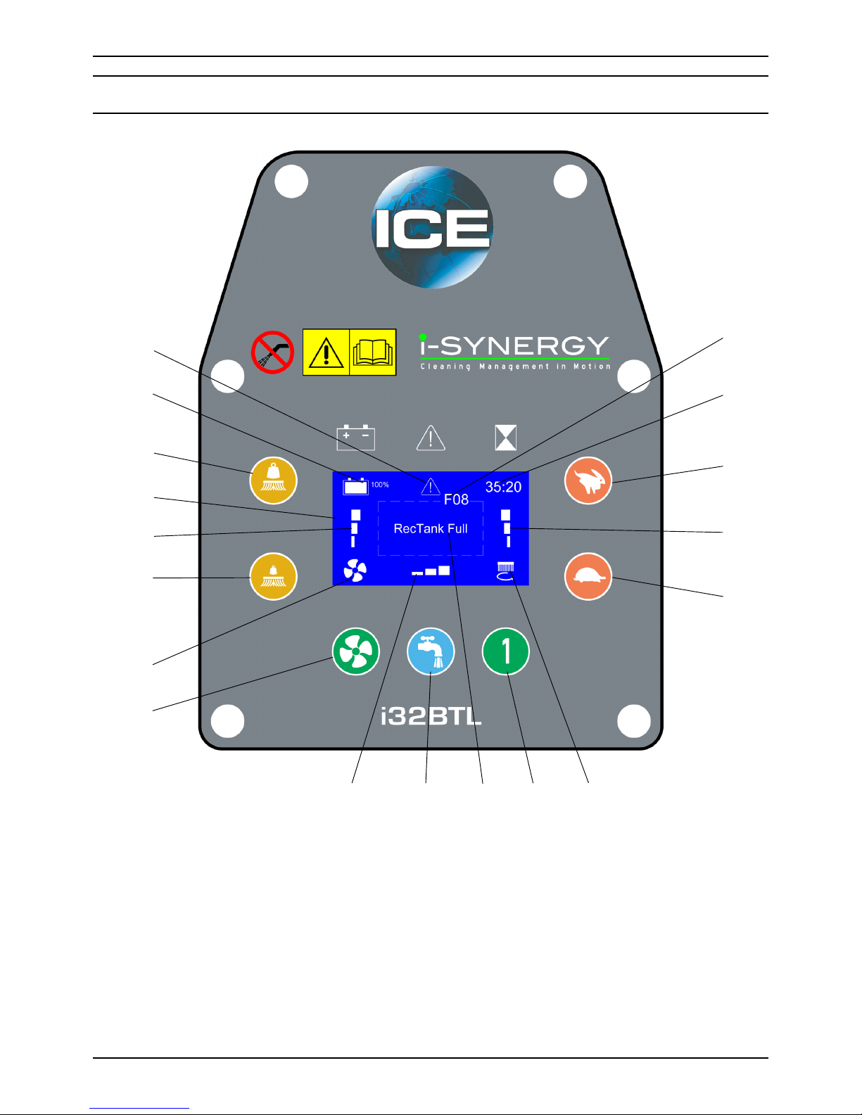
PANEL COMPONENTS
1. Fault indicator
2. Battery meter
3. Brush pressure increase button
4. LED display screen
5. Brsuh pressure indicator
6. Brush pressure decrease button
7. Vacuum motor indicator
8. Vacuum motor switch
9. Solution ow indicator
10. Solution ow adjusting button
11. Fault message display area
12. 1-Step scrub head up/down button
13. Brush motor indicator
14. Speed decrease button
15. Speed indicator
16. Speed increase button
17. Timer
18. Fault code
1
2
3
4
5
6
7
8
9
10 11 12 13
14
15
16
17
18
Page 7
7
ICE i28BTL / i32BTL
OPERATOR MANUAL
i-synergyTM collects operational data from
cleaning machines and transmit the information
to ICE’s server. The ICE server generates daily
reports and send them to designated end users
by email. From these reports, end users will
have information about machines’ usage and
even specic timings.
Besides, i-synergy
TM
also collects data on
lithium-ion battery, vacuum motor, brush
deck motor, transaxle, and other electrical
components at least once every minute when
the machine is in use and even during battery
charging.
i-synergy
TM
will send notications instantly
to the ICE server in case of any malfunction.
ICE maintenance personnel will receive a
SMS within minutes from the ICE server for
immediate servicing.
UNCRATING MACHINE
Be sure and check packing carton for any damage.
Immediately report any damage to carrier. Check
the contents of package to ensure that the
following items are included:
• Machine
• Lithium-ion Batteries
• Squeegee assembly
• 2-Pad Drivers
INSTALLING BATTERIES
The machine uses the Lithium-ion batteries,
the batteries are already in the machine upon
delivery; However you will need to connect the
Lithium ion batteries to the machine.
WARNING: Fire or Explosion Hazard.
Keep sparks and open ames away! Keep
battery compartment open when charging.
1. Turn off the machine.
2. Open recovery tank to gain access to battery
compartment.
3. Carefully place the Lithium-ion batteries into the
compartment. Place the battery brace at the
rear of the batteries.
DO NOT DROP BATTERIES INTO
COMPARTMENT!
4. Plug the batteries connector to the machine
adaptor, connect machine i-synergy
TM
COM
port with the batteries.
MACHINE SET UP
PRE-OPERATION CHECKS
1. Sweep or dust mop the surface to be cleaned.
2. Check battery meter to make sure batteries are
fully charged. (See BATTERY CHARGING)
3. Check that squeegee is properly installed.
4. Check that brushes / pads is properly installed.
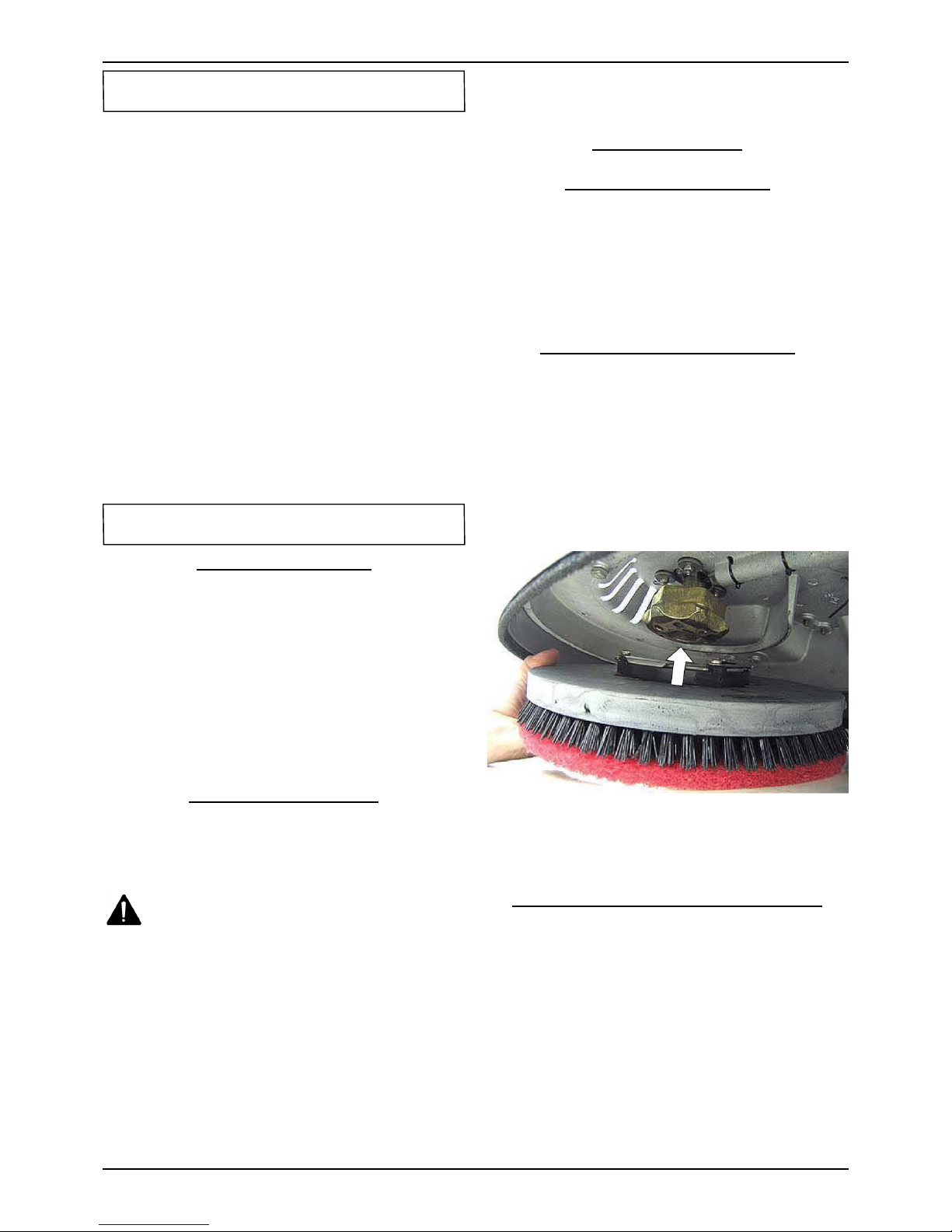
INSTALLING BRUSHES OR PADS
1. Turn off the 1-Step scrub head up/dwon button
(Panel components, item #12) and Raise the
Scrub head off the oor, then stop machine on
the level surface, ensure the machine is turned
off.
2. If using the Pad Driver, rst attach the
appropriate pad to the pad driver surface.
3. Align the pad driver or brush under the motor
hub and push it upward to engage.
4. To remove the pad driver or brush, raise the
scrub head and push the pad release plunger
(Machine components, item #30) downward.
MOUNTING THE SQUEEGEE ASSEMBLY
1. Lift the squeegee lift lever (Machine
components, item #8)to the upward position.
2. Mount the squeegee assembly to the squeegee
pivot bracket. make sure the knobs are
completely seated into the slots before securing
knobs.
3. Connect the vacuum hose to the squeegee
assembly. Loop the hose by using the hose clip
provided.
4. Check the squeegee blades for proper
adjustment.
i-synergyTM INTRODUCTION
MACHINE SET UP & INSTALLATION
Page 8
8
ICE i28BTL / i32BTL
OPERATOR MANUAL
FILLING THE SOLUTION TANK
The machine is equipped with a hose ll-port
(Machine components, item #7) at the rear of
the machine, and a bucket ll-port (Machine
components, item #26)located under the recovery
tank. Before accessing the bucket ll-port make
sure that the recovery tank is empty.
Fill the solution tank to the "100L" level on the
solution tank sight gauge. When using the bucket
ll-port, stop lling when the level reaches the
bottom edge of the ll-port.
NOTE: When lling the solution tank with a
bucket, make sure that the bucket is clean. Do not
use the same bucket for lling and draining the
machine.
WARNING: Do not put any ammable
materials into solution tank. this can cause an
explosion or a re. Only use recommended
cleaning chemicals. Contact your janitorial
supply distributor for recommendations on
proper chemicals.
WARNING: Do not operate machine
unless you have read and understand this
manual.
1. Swipping the ID card (Machine components,
item #18) to turn on the machine.
2. Check the LED display screen (Panel
components, item #4), if there are fault condes
(Panel components, item #18) and the Fault
indicator (Panel components, item #1) in blink,
please DO NOT operate the machine unless the
faults have been eliminated (please see FAULT
CODES AND ELIMINATE section).
3. Turn on the 1-Step scrub head up/down
button, the scrub head will be lowered down
automatically.
4. Lower squeegee assembly to the oor by
lowering the Squeegee lift lever.
5. Check the solution ow indicator (Panel
components, item #9), press the Solution ow
adjusting button (Panel components, item #10)
to get a desired solution ow.
NOTE: Solution will not begin to ow until the
control handle bail is pulled.
6. Turn on the Vacuum motor switch(Panel
components, item #8).
7. Pull the Control handle bail (machine
components, item #17) backwards to start
scrubbing .The machine will automatically
propel forward. To reverse the machine, simply
push the control handle bail forward.
NOTE:
Raise squeegee when reversing machine.
8. The scrubbing speed can be adjusted, press
the Speed increase/ decrease button (Panel
components, item #14, #16) to a desired speed.
NOTE: 45-60 meters (150-200 ft)per minute is
the recommended scrubbing speed.
9. The brush pressure can be adjusted, press the
Brush pressure increase/ decrease button
(Panel components, item #3,#6) to get a
desired brush pressure.
10. To stop scrubbing, release the control handle
bail, turn off the 1-Step scrub head up/down
button to raise he scrub head assembly, raise
the squeegee assembly.
WARNING: Fire Or Explosion Hazard. Do
Not Pick Up Flammable Materials Or Reactive
Metals.
1. Go slow on inclines and slippery surfaces. Do
not operate the machine on inclines that exceed
5% (3°).
2. Do not keep the machine in the same position
with pad / brush spinning, keep the machine
moving to prevent damage to oor nish.
3. If the squeegee assembly leaves streaks on the
oor, raise the squeegee off the oor and wipe
the blades down with a damp cloth. Pre-sweep
the area to prevent leaving streaks on the oor.
4. Pour a recommended defoamer into the
recovery tank if excessive foam appears.
WARNING: Do not allow foam to enter
the oat shut-off screen, vacuum motor
damage will result. Foam will not activate the
oat shut-off screen.
5. Occasionally check the battery meter(Panel
components, item #2). when the battery is very
low, stop scrubbing and recharge the batteries.
WARNING: When battery meter is in the
red, do not continue to operate the machine.
Battery damage may result.
MACHINE OPERATION
WHILE OPERATING MACHINE
Page 9

9
ICE i28BTL / i32BTL
OPERATOR MANUAL
6. When the solution tank runs empty, press the
1-Step switch raise the brush head. Keep the
squeegee down and continue to vacuum until all
the dirty water is picked up.
NOTE: Brush motors will not work when
the scrub head assembly raised.
NOTE: See TANK DRAINING section to learn
how to drain recovery and solution tanks.
CIRCUIT BREAKER / FUSES
The machine is equipped with 2 resettable circuit
breakers(machine components, item #5, item#
6) to protect the main controller from damage. If
the circuit breakers should trip, it can't be reset
immediately. You must rst determine what caused
the breaker to trip, and allow the motor to cool
down and then you can manually reset the circuit
breakers.
The machine is also equipped with a 150A fuse
to protect the Lithium-ion batteries from damage.
When replacing a fuse never substitute a higher
Amps rated fuse than specied.
HOUR METER
The hour meter (Panel machine components, item
#17) records the number of total hours the brush
motor has been powered on. Use the hour meter
to determine when to perform recommended
maintenance procedures and to record service
history.
EMERGENCY STOP BUTTON/ BRAKE
The machine is equipped with an Electromagnetic
Brake Mechanism on the Transaxle. When in
case of Emergency, release the Control Handle
bail or strike the Emergency stop button (Machine
components, item #4), the machine will be braked
and then stop. Reset the emergency stop button,
turn on the machine, and then pull the control
handle bail, the machine will be restart.
NOTE: The machine can not be moved unless the
Main Power and the Control Handle bail be turned
on.
WARNING: Do Not Change the Default
Settings of the Electromagnetic Brake
Mechanism unless Authorized, otherwise it
may cause Machine Damage or Personal Injury.
Contact the Authorized Service center for
machine repairs.
1. Turn the machine off.
2. With the squeegee and scrub head in their "up"
position, transport machine to approved area for
draining tank(s).
DRAINING THE RECOVERY TANK
Any time scrubbing is completed, or when relling
solution tank, the recovery tank should be drained
and cleaned.
WARNING: If the recovery tank is not
drained when the solution tank has been
relled, foam or water may enter the oat shut-
off screen and cause damage to the vacuum
motor.
1. While holding the drain hose (Machine
components, item #3) upward, remove the cap
and lower hose to drain.
2. Open the recovery tank cover and rinse out the
tank. Use a rag to remove any excess dirt.
3. Clean the oat shut-off screen and debris tray
located in the recovery tank .
DRAINING THE SOLUTION TANK
Any time scrubbing operation is completed, the
solution tank should be drained and cleaned.
1. Pull the solution tank level hose(Machine
components, item #12) off the hose tting, this
will allow the solution to ow freely into a bucket
or oor drain.
2. Remove the cover of the lter assembly
(Machine components, item #10) to drain the
solution tank, check the lter screen and clean
up it if necessary.
3. Rinse the solution tank with clean water after
every use. This will help prevent chemical
buildup and clogging of the solution lines.
4. After rinsing out the tank, securely reconnect
the tank level hose to the hose tting, replace
the lter assembly cover and be sure the
lter screen and the "O" ring is in the correct
position.
TANK DRAINING
Page 10
10
ICE i28BTL / i32BTL
OPERATOR MANUAL
BATTERY CHARGING
WARNING: Fire Or Explosion Hazard.
Keep Sparks and Open Flame Away. Keep
Battery Compartment Propped Open When
Charging.
Only use ICE supplied or approved batteries
charger, use unapproved charger may cause
damage to the batteries and machine.
Batteries chargers specications:
• Applicable to charging Lithium-ion batteries
• Automatic shut off circuit
• Output current of 30 Amps
• Output voltage of 24 volts
1. Place machine in a well ventilated area.
2. Turn the machine off.
3. Connect the charger's AC power supply cord to
a properly grounded receptable.
4. Prop up the recovery tank by the support stand
(Machine components, item #20) for ventilation
when charging.
5. The charger will automatically begin to charge
and will automatically shut off once the batteries
are fully charged.
6. Upon completion of charging, disconnect the
AC power supply cord.
WARNING: Before performing any
maintenance on the machine, be sure that
the power is turned off, or the batteries are
disconnected!
WARING: Repairs are to be completed
by Authorized service centers only. Any repairs
completed by unauthorized persons will avoid
the warrenty.
DAILY MAINTENANCE
1. Remove pad driver/ brush and clean with
approved cleaner.
2. Drain recovery and solution tanks completely
and rinse out with clean water. Visually check
the recovery tank for debris and clean out as
necessary.
3. Raise the squeegee assembly off oor and wipe
it down with a damp towel. Be sure to store the
squeegee in the up position.
4. Remove the oat shut-off assembly and rinse it
out with clean water.
5. Clean machine with an approved cleaner and a
damp towel.
6. Recharge the batteries.
7. Check the condition of the squeegee blade
wiping edge, rotate blade if worn.
MONTHLY MAINTENANCE
1. Clean the battery tops to prevent corrosion.
2. Check for loose battery cable connections.
3. Inspect and clean the recovery tank cover seal.
Replce it if damaged.
4. Lubricate all grease points and pivot points with
silicon spray and approved grease.
5. Check the machine for loose nuts and bolts.
Check the machine for leaks.
MACHINE STORAGE
1. Always store the machine indoors.
2. Always store the machine in a dry area.
3. Always store the machine in its upright position.
4. Always store the machine with the pad driver/
brush raised off the oor.
5. Always store the machine with the squeegee
assembly raised off the oor.
6. If storing in an area which may reach freezing
temperatures, be sure to drain all uids from the
machine prior to storage. Any damage caused
by freezing temperatures will not be covered by
the warranty.
7. Drain the recovery tank.
8. Drain the solution tank of all uid.
PREVENTATIVE MAINTENANCE
Page 11

11
ICE i28BTL / i32BTL
OPERATOR MANUAL
FAULT CODE & SOLUTION
The machine is equipped with a LED display screen
(Panel components, item # 4), the LED screen will
display the operating hours (Panel components,
item # 17) and the battery level status (see Panel
components, item # 2).
When the machine detects a fault, there will be a
Fault code (Panel components, item #18) & Fault
message (Panel components, item #11) display
on the LED screen, and the Fault indicator (Panel
components, item #1) will ash continuously,
accompany an audible alarm Occasionally.
Once fault occuring, please DO NOT continue
operate the machine unless the fault are eliminated.
Turn off the machine, then to solve the fault, the
fault code & message will be eliminated when
machine restart.
If the fault is occurred frequently, or the fault can't
be eliminated, please contact ICE service center.
Please refer to the below table to determine the
fault cause and the solution.
FAULT
CODE
FAULT MESSAGE FAULT CAUSE SOLUTION
F03
Bru Actt O.L.
RESTART!
Scrub head lifting actuator is overload
Turn off the machine,after a moment,
RE-START machine.
F04
Vac Mtr O.L.
RE-START!
Vacuum motor overload
F05
Left Bru Mtr O.L.
RE-START!
Left brush motor is overload
F06
Right Bru Mtr O.L.
RE-START!
Right brush motor is overload
F07
Propel Mtr O.L.
RE-START!
Propel motor overload
F08 RecTank Full Recovery tank is full Drain the Recovery tank
F10
Batt Low
Charge Batt
Battery is low Charge the battery
F11
Batt Empty
Charge Batt NOW
Battery is empty Charge the battery NOW
F12 Brake Wiring Error Bad Brake wiring Check the brake wiring
F14 Replace Brake Assy Bad Brake assembly Replace the brake assembly
F16
Control Unit Overheat!
Wait
Control Unit Overheat
Turn off the machine,after a moment,
RE-START machine
F17 Replace Control Unit Control Unit Fault Replace the control unit
F20 Check Left Brush motor Bad left brush motor Check left brush motor/ wiring
F21 Check Vac Mtr Bad Vacuum motor or wiring Check the vacuum motor / Wiring
F22 Check Soln Solenoid Solution solenoid wiring fault Check the wiring & Contactors
F23 Replace Soln solenoid Bad Solution solenoid Replace the solution solenoid
F24 Check Propel Motor Bad propel motor Check the propel motor / Wiring
F25 Check Right Brush motor Bad right brush motor Check right brush motor/ wiring
F40 Check Proximity Sw Proximity switch fault Check the Proximity switch
F41 Release Handle Operation mistake Release the control handle bail
F42 Replace Control Unit Bad Control Unit Replace the control unit
F43
Turn Dead Sw Off
RE-START!
Emergency stop button activated
Release emergency stop button and
restart machine
F44 Replace Control Unit
Bad Control Unit
Contact service center, Replace the
Control Unit
F45 Return Control Unit
F46 Return Control Unit
F47 Return Control Unit
F48 Return Control Unit
Page 12

12
ICE i28BTL / i32BTL
OPERATOR MANUAL
PROBLEM CAUSE SOLUTION
Machine will not
operate
Control handle bail not pulled
Pull control handle bail
Batteries need to be charged
Charge batteries
Bad lithium-ion batteries
Replace batteries
Emergency stop button activated
Reset Emergency stop botton
Main PCB fuse blown
Contact ICE service center
Faulty i-synergy
TM
module
Contact ICE service center
Brush motor will
not operate
1-STEP scrub head up/down switch is off
Turn on the 1-STEP switch
Battery meter lockout activated
Recharge batteries
Faulty control handle bail switch
Contact ICE service center
Faulty brush motor or wiring
Contact ICE service center
Worn Motor carbon brushes
Contact ICE service center
Machine does
not propel
the Control handle bail not pulled Pull the control handle bail
Faulty transaxle motor or wiring
Contact ICE service center
Worn Motor carbon brushes
Contact ICE service center
Vacuum motor
will not operate
Faulty vacuum motor or wiring
Contact ICE service center
Worn Motor carbon brushes
Contact ICE service center
Little or no
solution ow
Ball valve set too low or shut off
Turn on the ball valve
Solution ow control knob set too low or
shut off
Adjust solution control ow knob
Clogged solution tank lter or solution
hose
Clean solution tank filter or flush out
solution hose
Clogged solution Solenoid valve
Remove valve and clean
Poor water pick
up
Recovery tank is full
Drain recovery tank
Loose drain hose cap
Tighten cap
Clogged oat shut-off screen located in
recovery tank
clean screen
Clogged squeegee assembly
Clean squeegee assembly
Worn squeegee blades
Replace or rotate squeegee blades
Incorrect squeegee blade deection
Adjust squeegee blade height
Loose vacuum hose connections
Secure hose connections
Clogged vacuum hose
Remove clogged debris
Damaged vacuum hose
Replace vacuum hose
Recovery tank cover not in place
Properly position cover
Damaged recovery tank cover seal
Replace seal
Faulty vacuum motor
Contact ICE service center
Low battery charge
Recharge batteries
Short run time
Low battery charge
Fully recharge batteries
Defective batteries
Replace batteries
Batteries need maintenance
See BATTERY MAINTENANCE
Faulty battery charger
Repair or replace battery charger
Down pressure lever is set for extra scrub
head pressure
Lower down pressure lever
BASIC TROUBLESHOOTING
Page 13

13
ICE i28BTL / i32BTL
OPERATOR MANUAL
TECHNICAL SPECIFICATIONS
MODEL i28BTL i32BTL
DIMENSIONS L 61.02 in / 1,550 mm 62.21 in / 1,580 mm
DIMENSIONS W 30.51 in / 775 mm 34.06 in / 865 mm
DIMENSIONS H 44.49 in / 1,130 mm 44.49 in / 1,130 mm
WEIGHT 352.74 lbs / 160 Kg 374.79 lbs / 170 Kg
WEIGHT with BATTERIES 661.39 lbs / 300 Kg 683.43 lbs / 310 Kg
SOLUTION TANK CAPACITY 26.42 Gal / 100 L
RECOVERY TANK CAPACITY 31.7 Gal / 120 L
SQUEEGEE WIDTH
Standard: 40.5 in / 1030mm
Option: 44.5 in / 1130mm
Standard: 46.5 in / 1185mm
Option: 44.5 in / 1130mm
CLEANING PATH WIDTH 27.56 in / 700 mm 31.5 in / 800 mm
PRODUCTIVITY RATE 30,677 ft
2
/ 2,850 m2 h 34,983 ft2 / 3,250 m2 h
DRIVE SYSTEM Transaxle, 24VDC, 0.27 hp / 0.2 KW
TRAVEL SPEED, MAXIMUM
Cleaning: 65m / Min Transporting: 72 m / Min
213.25 ft / Min 236.22 ft / Min
MINIMUM AISLE TURN 63 in / 1,600 mm
PAD/BRUSH PRESSURE
39.68 lbs / 18kg
79.37 lbs / 36kg
119.05 lbs / 54kg
SOLUTION FLOW RATE
0 ~ 2.7 L / Min
0 ~ 0.66 Gal / Min
BRUSH MOTOR 0.75 hp / 0.55 KW × 2
VACUUM MOTOR 0.8 hp / 0.6 KW
WATER LIFT - AIR FLOW 65 in / 1,650 mm
BATTERIES Lithium-ion batteries, 240AH
RUN TIME PER CHARGE 3.5~4 Hours
VOLTAGE DC 24V
DECIBEL RATING AT
OPERATOR'S EAR, INDOORS
68 dB(A)
GRADE LEVEL, MAX 5% (3°)
Page 14

14
ICE i28BTL / i32BTL
PARTS LIST
RECOVERY TANK GROUP
Page 15

15
ICE i28BTL / i32BTL
PARTS LIST
RECOVERY TANK GROUP
DIA
NO.
PART
NUMBER
DESCRIPTION
NO
REQ'D
1 8111001 GASKET 1
2 8131003 CAP 1
3 8210102 RECOVERY TANK 1
4 8131010 DRAIN HOSE 1
5 1962050 CLAMP 1
6 8111300 HINGE ASSEMBLY 2
7 1421618 FLAT WASHER M6×18×1.6 10
8 1021616 HEX BOLT M6 X 16 12
9 8210207 CABLE 1
10 1421612 FLAT WASHER M6×12×1.6 5
11 8112005 GASKET, VACUUM MOTOR 1
12 1121605 HEX NUT M6 3
13 8210209 STUD M6×110 3
14
8210260 AMETEK VACUUM MOTOR 24VDC, KIT 1
8132006 CARBON BRUSH, VACUUM MOTOR 2
15 1123608 LOCK NUT M6 3
16 1914300 TIE, NYLON, 5X300 1
17 8132007 MUFFLER, VACUUM MOTOR 1
18 4010316 ICE LOGO 1
19 8111008 BRACKET 1
20 1421816 FLAT WASHER M8×16×1.6 2
21 8111007 RECOVERY TANK SUPPORT 1
22 8115404 SLEEVE, P/M 1
23 1021830 HEX BOLT M8×30 1
24 8111016 PLATE 2
25 1221512 SCREW M5×12 2
26 8111015 FLOAT, SHUT-OFF 1
27 8111014 FLOAT ADAPTER 1
28 8210201 RECOVERY TANK COVER SEAL 1
29 8011005 CAP 1
30 8210103 RECOVERY TANK COVER 1
31 8111022 WARNING LABEL 1
Page 16

16
ICE i28BTL / i32BTL
PARTS LIST
SOLUTION TANK GROUP
Page 17

17
ICE i28BTL / i32BTL
PARTS LIST
SOLUTION TANK GROUP
DIA
NO.
PART
NUMBER
DESCRIPTION
NO
REQ'D
1 6210131 NYLON, CLAMP 12
2 1421510 FLAT WASHER M5×10×1 32
3 1221512 SCREW M5×12 24
4 1123507 LOCK NUT M5 6
5 8210111 BRACKET, BATTERY CHARGER MNTG 1
6 8210117 CAP, CHARGER 1
7 1421612 FLAT WASHER M6×12×1.6 12
8 1021616 HEX BOLT M6 X 16 10
9 8311720 ON BOARD LI-ION BATTERY CHARGER 1
10 8112030 POWER CORD, BATTERY CHARGER, US 1
11 1222641 SCREW M6 X 40 2
12 8210112 HOOK, CORD 2
13 1321213 SELF-TAPPING SCREW ST4.2X13 2
14 8210113 CAP, SOLUTION FILL 1
15 8210101 SOLUTION TANK 1
16 4010316 ICE LOGO 2
17 8130099 I-SYNERGY LOGO 2
18 8210145 CLEAN TUBING 1
19 1962025 CLAMP 16-25mm 1
20 8210151 LABEL, LEFT SIDE 1
21 9324225 LITHIUM-ION BATTERY, 240AH 1
22 8210104 COVER, FRONT 1
23 1321110 SELF-TAPPING SCREW ST3.5 ×10 3
24 1421409 FLAT WASHER M4×9×0.8 5
25 8133610 LED LIGHT KIT 1
26 8133601 LED LIGHT MNTG BASE 1
27 1221520 SCREW M5X20 3
28 8133602 LED LIGHT COVER 1
29 8210531 KNOB, M6 2
30 1535630 SET SCREW M6 ×30 2
Page 18

18
ICE i28BTL / i32BTL
PARTS LIST
SOLUTION TANK GROUP
DIA
NO.
PART
NUMBER
DESCRIPTION
NO
REQ'D
31 1421618 PLAIN WASHER 6×18×1.6,SS 4
32 8113112 BUSHING 2
33 8210152 LABEL, RIGHT SIDE 1
34 8113030 SEAL 1
35 8113002 COVER 1
36 8113007 STRAP 1
37 8210168 PLATE 2
38 8210163 CONNECTOR HOUSING 1
39 8210723 BATTERY CONNECT CABLE, RED 1
40 8210724 BATTERY CONNECT CABLE, BLACK 1
41 8210164 BRACKET, CONNECTOR 1
42 1422515 SPRING WASHER,M5 2
43 1021512 HEX HEAD SCREW, M5X12 2
44 1221525 PAN HEAD SCREW, M5X25 2
Page 19

19
ICE i28BTL / i32BTL
PARTS LIST
CONTROL CONSOLE GROUP
Page 20

20
ICE i28BTL / i32BTL
PARTS LIST
CONTROL CONSOLE GROUP
DIA
NO.
PART
NUMBER
DESCRIPTION
NO
REQ'D
1 1221512 SCREW M5×12 17
2 1422513 LOCK WASHER M5 6
3 1421510 FLAT WASHER M5×10×1.0 13
4
8210486 CONTROL PANEL DECAL, i28BTL 1
8210487 CONTROL PANEL DECAL, i32BTL 1
5 8210481 CONTROL PANEL 1
6 8134015 GASKET 1
7 8210493 CONTROL PANEL PCB (LI/EN) 1
8 1221306 SCREW M3×6 6
9 8134005B CONTROL HOUSING,i32BTL 1
10 8310740 CIRCUIT BREAKER, 5A 2
11 1221421 SCREW M4×20 2
12 1421409 FLAT WASHER M4×∮9×0.8 2
13 8124715A EMERGENCY STOP SWITCH, KIT 1
14 8144030 BASE, CIRCUIT BREAKERS MNTG 1
15 8124008 SPRING 2
16 8124716 LED LIGHT 1
17 8124007 BUTTON,EMERGENCY STOP 1
18 8124710 EMERGENCY STOP SWITCH KIT 1
19 8144026 LABEL, CIRCUIT BREAKER 1
20 8134060 PLATE, ON BOARD BATTERY CHARGER 1
21 8134061 CLEAR COVER 1
22 1421618 PLAIN WASHER M6×∮18×1.6,SS 12
23 1422616 LOCK WASHER, M6 20
24 1021616 HEX BOLT M6 X 10 2
25 8114705 STAND-OFF, M6 2
26 8310480 FUSE,150A 1
27 1021616 HEX BOLT M6 X 16 5
28 8114005 CONNECTOR 1
29 1021840 HEX BOLT M8×40 2
30 1422821 LOCK WASHER M8 12
31 1421828 FLAT WASHER M8×∮28×3 2
32 1021630 HEX HEAD BOLT M6×30,SS 1
33 8210413 CABLE, SQGE LIFT 1
34 8014101 LIFTING ROPE SPACER 1
35 1021512 HEX HEAD BOLT M5×12,SS 2
Page 21

21
ICE i28BTL / i32BTL
PARTS LIST
CONTROL CONSOLE GROUP
DIA
NO.
PART
NUMBER
DESCRIPTION
NO
REQ'D
36 1421515 FLAT WASHER M5×15×1.0 1
37 1123608 LOCK NUT M6 3
38 8014012 BAFFLE 1
39 811 3111 NYLON FLAT WASHER ∮12.9×∮25.4×0.8 1
40 1121605 HEX NUT M6 2
41 8134501 BRACKET 1
42 8134508 SLEEVE 1
43 1421132 FLAT WASHER 12×32×1.5 1
44 8014010 SQUEEGEE LIFTING HANDLE 1
45 8113104 BALL KNOB M8 1
46 1221515 PH SCREW M5×15,SS 2
47 6210111 CLAMP, DRAIN HOSE 1
48 1023612 HEX BOLT M6 X 12, COPPER 10
49 1423612 FLAT WASHER M6× ∮12×1, COPPER 10
50 8210490 MAIN CONTROLLER, i32BT 1
51 8134070 REAR PLATE, CONTROL CONSOLE 1
52 1421824 FLAT WASHER M8× ∮24×2 10
53 1021820 HEX BOLT M8×20 10
54 1221620 PH SCREW M6×20 2
55 8134768 RFID BOARD 1
56 8134035 LABEL, i-SYNERGY
TM
CARD SCANNING 1
57 8114712 MICRO SWITCH 1
58 8124743 MICRO SWITCH 1
59 1434300 LOCK WASHER, TOOTH, M3 4
60 1021320 SCREW M3 X 20 4
61 1123305 LOCK NUT M3 4
62 8134022 BRACKET,SWITCH 1
63 8114402 BRACKET, SPRING 1
64 1521616 SCREW M6X16, HEX SCOKET 2
65 1534608 SET SCREW M6 ×8 4
66 8134300 LEVER, BAIL 1
67 8114300 ACTUATOR 1
68 8114306 SPRING 1
69 1535630 SET SCREW M6 ×30 1
70 8114101 SHAFT 1
Page 22

22
ICE i28BTL / i32BTL
PARTS LIST
FRAME & TRANSAXLE GROUP
Page 23

23
ICE i28BTL / i32BTL
PARTS LIST
FRAME & TRANSAXLE GROUP
DIA
NO.
PART
NUMBER
DESCRIPTION
NO
REQ'D
1 8211507 KNOB M8 ×60 1
2 8211505 SHOULDER SCREW,M12 1
3 1421132 FLAT WASHER 12×32×1.5 2
4 8135001
PLASTIC THRUST WASHER M12×∮ 30×1.5
2
5 8211506 SHAFT 1
6 1123608 LOCK NUT M6 7
7 1421618 FLAT WASHER M6×18×1.6 2
8 8211503 BRACKET, SQUEEGEE 1
9 8114511 BALL JOINT M6 1
10 8211504 SHOULDER SCREW,M8 4
11 8210508 SPIRNG 1
12 8211501 BRACKET, SQGE LIFT 1
13 1121807 NUT, M8 2
14 1421824 FLAT WASHER M8×24×2 12
15 8211502 BRACKET,SQGE SWING 1
16 1123810 LOCK NUT M8 11
17 8211508 BUSHING 1
18 1123115 LOCK NUT M12 1
19 8115203 COVER, WHEEL 2
20 1021816 HEX BOLT M8 × 16 2
21 1422821 LOCK WASHER M8 7
22 1421828 FLAT WASHER M8×28×2 2
23
8125200 WHEEL, 8 INCH 2
8225200 AIR FILLED WHEEL, 8 INCH, KIT (OPTION)
2
8225210 FOAM FILLED WHEEL, 8INCH, KIT (OPTION)
2
24 1021825 HEX BOLT M8 × 25 4
25 8210123 BRACKET, TRANSAXLE MNTG 2
26 1436019 RETAINING RING 19 2
27 8125403 WOODRUFF KEY 2
28 8210120A TRANSAXLE, 24VDC 1
29 1022800 HEX BOLT M8 X 100 1
30 1021030 HEX BOLT M10 X 30 8
31 1421020 FLAT WASHER 10×20×2.0 8
32 8210109 4" CASTER 2
33 1021820 HEX BOLT M8×20 5
34 8210115 ARM, SCRUB HEAD LIFTING 2
35 8210116 BUSHING 2
36 8210130 FRAME 1
37 1021855 HEX BOLT M8 × 55 2
38 1123012 LOCK NUT M10 8
39 8210186 BRACKET, PROXIMITY SENSOR 1
40 8134709A PROXIMITY SENSOR,KIT 1
41 1021616 HEX BOLT M6 × 16 2
42 8210138 SPACER (OPTION) 2
43 8210137 TOGGLE CLAMP, BRAKE (OPTION) 1
44 1021630 HEX BOLT M6 X 30 4
Page 24

24
ICE i28BTL / i32BTL
PARTS LIST
SCRUB HEAD GROUP
Page 25

25
ICE i28BTL / i32BTL
PARTS LIST
SCRUB HEAD GROUP
DIA
NO.
PART
NUMBER
DESCRIPTION
NO
REQ'D
1 8210807 PIN 2
2 8210309 PIN, COTTER 2
3 1021825 HEX BOLT M8 × 25 11
4 8210830 BRACKET, SCRUB HEAD LIFT, RIGHT 1
5 1421816 FLAT WASHER M8×16×1.6 14
6 8210806 BRACKET, ACTUATOR MNTG 1
7 8210820 BRACKET, SCRUB HEAD LIFT, LEFT 1
8 1123810 LOCK NUT M8 10
9
8210899 BRUSH MOTOR, 24VDC, 550W, KIT 2
8210850 CARBON BRUSH 2
10 1655025 KEY, 5X5X25 2
11 8210803 SPACER, RUBBER 2
12 8210808 KNOB, M10 2
13 8210809 SPRING 2
14
8220801 HOUSING, SCRUB HEAD, i28BTL 1
8210801 HOUSING, SCRUB HEAD, i32BTL 1
15 1022090 HEX BOLT M10 × 90 2
16 1421612 FLAT WASHER M6×12×1.6 8
17 1422616 LOCK WASHER, M6 8
18 1021620 HEX BOLT M6 × 20 8
19 8210804 SPACER 4
20 8210805 HUB, BRUSH DRIVE 2
21 1421828 FLAT WASHER M8×28×3.0 2
22 1422821 LOCK WASHER M8 2
23
8220810 BUMPER, SCRUB HEAD, i28BTL 2
8218050 BUMPER, SCRUB HEAD, i32BTL 2
24 1221635 SCREW, M6 × 35 12
25 1221640 SCREW, M6 × 40 4
26 1421618 FLAT WASHER M6×18×1.6 4
27 8210861 RETAINER BAR 4
28 8210862 SPRING, G-400S 4
29 9000004 CLUTCH, G-400S 4
30
9050014 BRUSH ASSEMBLY, 14 INCH, i28BTL (OPTION) 2
9050016 BRUSH ASSEMBLY, 16 INCH, i32BTL (OPTION) 2
31 1321325 SELF-TAPPING SCREW, ST5 X 25 6
32 9000003 CENTER LOCK, #3 2
33 8116040 SPACER, 6.5×14.5×7.0 6
34
9040014 PAD DRIVER, 14INCH, i28BTL 2
9040016 PAD DRIVER, 14INCH, i32BTL 2
35 1111 215 HEX NUT, M16 1
36 8210811 AJUSTMENT STUD, M16 1
37 8210810 BRACKET, ROLLER MNTG 1
38 1421824 FLAT WASHER M8×24×2 2
39 8115404 SLEEVE, P/M 1
40 8116009 PROTECTIVE WHEEL 1
41 1021830 HEX BOLT M8 × 30 1
Page 26

26
ICE i28BTL / i32BTL
PARTS LIST
SCRUB HEAD LIFT GROUP
Page 27

27
ICE i28BTL / i32BTL
PARTS LIST
SCRUB HEAD LIFT GROUP
DIA
NO.
PART
NUMBER
DESCRIPTION
NO
REQ'D
1 1123810 LOCK NUT M8 6
2 1421824 FLAT WASHER M8×24×2 10
3 8210306 BRACKET, GUIDE MNTG 1
4 1021825 HEX BOLT M8×25 2
5 1422821 LOCK WASHER M8 4
6 1021820 HEX BOLT M8×20 2
7 8210311 SPRING 2
8 8210312 WASHER, PM 2
9 8210314 BUSHING 1
10 8210310 GUIDE, ROLLER 1
11 8210313 ROLLER 1
12 1022800 HEX BOLT M8 X 100 1
13 8210316 BRACKET, SCRUB LIFT 1
14 1123008 LOCK NUT 3/8 2
15 1022811 HEX BOLT M8 X 110 1
16 8210319 SPRING 2
17 8210317 BRACKET, SPRING 1
18 1421132 FLAT WASHER 12×32×1.5 4
19 8210322 PIN 1
20 8210309 PIN, COTTER 2
21 8210318 SPRING 2
22 8210320 SLEEVE 2
23 8210321 BOLT, SHOULDER, 3/8 2
24 8210302 ACTUATOR, 24VDC 1
25 8210301 PIN 1
26 8210303 BRACKET, ACTUATOR MNTG 1
27 1421612 FLAT WASHER M6×12×1.6 4
28 1422616 LOCK WASHER M6 4
29 1021616 HEX BOLT M6 X 16 4
Page 28

28
ICE i28BTL / i32BTL
PARTS LIST
SQUEEGEE GROUP, 46.5INCH, OLD STYLE, i32BTL OPTION
Page 29

29
ICE i28BTL / i32BTL
PARTS LIST
SQUEEGEE GROUP, 46.5 INCH , OLD STYLE, i32BTL OPTION
DIA
NO.
PART
NUMBER
DESCRIPTION
NO
REQ'D
1 8210518 STAR KNOB M8 4
2 1021835 HEX BOLT M8×35 2
3 1421824 FLAT WASHER M8×24×2.0 2
4 8116009 PROTECTIVE WHEEL 2
5 8115404 BEARING, JOURNAL 2
6 1421816 FLAT WASHER M8×16×1.6 6
7 1021616 HEX BOLT M6×16 8
8 1421618 FLAT WASHER M6×18×1.6 8
9 8210515 BRACKET, ROLLER MNTG 2
10 8118300 RIGHT BRACKET 1
11 8210511 SQUEEGEE HOUSING 1
12 1123810 LOCK NUT M8 2
13 1121807 HEX NUT M8 4
14 1221575 SCREW M5×75 1
15 8210525 SHORT CLAMP ASSEBLY 1
16 8118624 SHAFT 1
17 8118623 SPACER 1
18 1123507 LOCK NUT M5 1
19
8210520 CLAMP ASSEMBLY, SQUEEGEE 1
8211520 CLAMP ASSEMBLY, SQUEEGEE(OPTION) 1
20 1022845 HEX BOLT M8×45 1
21 8210527 WHEEL, 2 INCH 1
22 1021860 HEX BOLT M8×60 4
23 1221516 SCREW M5×16 2
24
8210514 SQUEEGEE BLADE, REAR, LINATEX 1
8210517 SQUEEGEE BLADE, REAR, PU (OPTION) 1
25 8210512 RETAINER,SQUEEGEE 1
26 1021625 HEX BOLT M6×25 2
27
8210513 SQUEEGEE BLADE, FRONT, LINATEX 1
8210516 SQUEEGEE BLADE, FRONT, PU (OPTION) 1
28 8210519 CLAMP, FRONT BLADE 1
29 8210531 KNOB, M6 2
30 8210530 KNOB, M6 × 12 6
31 8118400 CASTER, 2 INCH 2
32 8118200 LEFT BRACKET 1
33 1121008 HEX NUT M10 2
34 8118109 HOLDER VACUUM HOSE 1
35 8118006 VACUUM HOSE 1
36 1962050 CLAMP 1
37 8210510 SQUEEGEE ASSEMBLY FOR i32BTL, 46.5 INCH, OPTION 1
Page 30

30
ICE i28BTL / i32BTL
PARTS LIST
SQUEEGEE GROUP, 46.5 INCH, NEW STYLE, i32BTL STANDARD
Page 31

31
ICE i28BTL / i32BTL
PARTS LIST
SQUEEGEE GROUP, 46.5 INCH, NEW STYLE, i32BTL STANDARD
DIA
NO.
PART
NUMBER
DESCRIPTION
NO
REQ'D
1 8210518 STAR KNOB M8 4
2 1021835 HEX BOLT M8×35 2
3 1421824 FLAT WASHER M8×24×2.0 2
4 8116009 PROTECTIVE WHEEL 2
5 8115404 BEARING, JOURNAL 2
6 1421816 FLAT WASHER M8×16×1.6 6
7 1021616 HEX BOLT M6×16 8
8 1421618 FLAT WASHER M6×18×1.6 8
9 8210515 BRACKET, ROLLER MNTG 2
10 8118300 RIGHT BRACKET 1
11 8230501 SQUEEGEE HOUSING 1
12 1123810 LOCK NUT M8 2
13 1221575 SCREW M5×75 1
14 8210525 SHORT CLAMP ASSEBLY 1
15 8118624 SHAFT 1
16 8118623 SPACER 1
17 1123507 LOCK NUT M5 1
18 1022845 HEX BOLT M8×45 1
19 8210527 WHEEL, 2 INCH 1
20 8210520 CLAMP ASSEMBLY, SQUEEGEE 1
21
8230504 SQUEEGEE BLADE, REAR, LINATEX 1
8230534 SQUEEGEE BLADE, REAR, PU (OPTION) 1
22 8230502 RETAINER,SQUEEGEE 1
23
8230503 SQUEEGEE BLADE, FRONT, LINATEX 1
8230513 SQUEEGEE BLADE, FRONT, PU (OPTION) 1
24 8118400 CASTER, 2 INCH 2
25 8118200 LEFT BRACKET 1
26 1121008 HEX NUT M10 2
27 8118109 HOLDER VACUUM HOSE 1
28 8118006 VACUUM HOSE 1
29 1962050 CLAMP 1
30 8230500
SQUEEGEE ASSEMBLY FOR i32BTL, 46.5 INCH, STANDARD
1
Page 32

32
ICE i28BTL / i32BTL
PARTS LIST
SQUEEGEE GROUP, 44.5 INCH, i32BTL OPTION
Page 33

33
ICE i28BTL / i32BTL
PARTS LIST
SQUEEGEE GROUP, 44.5 INCH, i32BTL OPTION
DIA
NO.
PART
NUMBER
DESCRIPTION
NO
REQ'D
1 1021835 HEX BOLT M8×35 2
2 1421824 FLAT WASHER M8×24×2.0 2
3 8116009 PROTECTIVE WHEEL 2
4 8115404 BEARING, JOURNAL 2
5 1121008 HEX NUT M10 2
6 8220501 SQUEEGEE HOUSING 1
7 8210518 STAR KNOB M8 2
8 1123810 LOCK NUT M8 2
9 1221575 SCREW M5×75 1
10 8210525 SHORT CLAMP ASSEBLY 1
11 8118624 SHAFT 1
12 8118623 SPACER 1
13 1123507 LOCK NUT M5 1
14 8220521 CLAMP ASSEMBLY, SQUEEGEE 1
15
8220513 SQUEEGEE BLADE, REAR, LINATEX 1
8220523 SQUEEGEE BLADE, REAR, PU (OPTION) 1
16 8118400 CASTER, 2 INCH 2
17
8220514 SQUEEGEE BLADE, FRONT, LINATEX 1
8220524 SQUEEGEE BLADE, FRONT, PU (OPTION) 1
18 8220518 FRONT CLAMP, LEFT 1
19 1121403 HEX NUT M4 1
20 1123406 LOCK NUT M4 1
21 1421409 FLAT WASHER M4×9×0.5 1
22 1211435 SCREW M4×35 1
23 8220515 FRONT CLAMP, LEFT 1
24 8118109 HOLDER VACUUM HOSE 1
25 8118006 VACUUM HOSE 1
26 1962050 CLAMP 1
27 8220500
SQUEEGEE ASSEMBLY FOR i32BTL, 44.5 INCH, OPTION
1
Page 34

34
ICE i28BTL / i32BTL
PARTS LIST
SQUEEGEE GROUP, 40.5 INCH , i28BTL STANDARD
Page 35

35
ICE i28BTL / i32BTL
PARTS LIST
SQUEEGEE GROUP, 40.5 INCH , i28BTL STANDARD
DIA
NO.
PART
NUMBER
DESCRIPTION
NO
REQ'D
1 1123810 LOCK NUT M8 2
2 1421824 FLAT WASHER M8×∮24×2.0 4
3 8116009 PROTECTIVE WHEEL 2
4 8115404 BEARING, JOURNAL 2
5 1021616 HEX BOLT M6×16 2
6 1421612 FLAT WASHER M6×∮12×1.6 2
7 1121008 HEX NUT M10 2
8 8118300 RIGHT BRACKET 1
9 8310550 CASTER, 2 INCH 2
10 8310514 CLAMP ASSEMBLY 1
11
8310536 SQUEEGEE BLADE, REAR, LINATEX 1
8310546 SQUEEGEE BLADE, REAR, PU (OPTION) 1
12 8310511 SQUEEGEE HOSING 1
13 1021835 BOLT, HEX HEAD, M8×35 2
14 8310512 RETAINER, SQUEEGEE 1
15
8310535 SQUEEGEE BLADE, FRONT, LINATEX 1
8310545 SQUEEGEE BLADE, FRONT, PU (OPTION) 1
16 8210518 STAR KNOB M8 2
17 8118200 LEFT BRACKET 1
18 8210525 SHORT CLAMP ASSEBLY 1
19 1221575 SCREW M5×75 1
20 8118624 SHAFT 1
21 8118623 SPACER 1
22 1123507 LOCK NUT M5 1
23 8118109 HOLDER VACUUM HOSE 1
24 8118006 VACUUM HOSE 1
25 1962050 CLAMP 1
26 8310570
SQUEEGEE ASSEMBLY FOR i28BTL, 40.5 INCH, STANDARD
1
Page 36

36
ICE i28BTL / i32BTL
PARTS LIST
SOLUTION GROUP
Page 37

37
ICE i28BTL / i32BTL
PARTS LIST
SOLUTION GROUP
DIA
NO.
PART
NUMBER
DESCRIPTION
NO
REQ'D
1 8119005 BALL VALVE, G1/2 1
2 8119007 ELBOW G1/2 1
3 8119006 CLAMP 5
4 8210901 TUBING ID=12MM L=330MM 2
5 8119100 FILTER ASSEBLY 1
6 8119101 BASE, FILTER ASSEMBLY 1
7
8119103 SCREEN, FILTER, 70 MESH 1
8119105 SCREEN, FILTER, 40 MESH (OPTION) 1
8 1622063 O RING 1
9 8119102 CAP, FILTER ASSEMBLY 1
10 1421510 FLAT WASHER M5×10×1 2
11 1221512 SCREW M5×12 2
12 8210902 TUBING ID=12MM L=480MM 1
13 8119002 ELBOW, TUBING BARB 1
14 8210903 TUBING ID=12MM L=120MM 1
15 1962016 CLAMP, 10-16mm 5
16 1221412 SCREW M4×12 2
17 1422411 LOCK WASHER M4 2
18 1421409 FLAT WASHER M4×9×0.8 2
19 8119003 SOLENOID VALVE,24VDC 1
20 1914300 TIE, NYLON, 5X300 5
21 8210904 TUBING ID=10MM L=180MM 2
22 8119008 FITTING, PLASTIC, TEE 1
Page 38

38
ICE i28BTL / i32BTL
WEAR AND TEAR PARTS
WEAR AND TEAR PARTS
DIA
NO.
PART
NUMBER
DESCRIPTION
NO
REQ'D
1
8125200 WHEEL, 8 INCH 2
8225200 AIR FILLED WHEEL, 8 INCH, KIT (OPTION) 2
8225210 FOAM FILLED WHEEL, 8INCH, KIT (OPTION) 2
2 8116009 PROTECTIVE WHEEL 3
3
8230503 SQUEEGEE BLADE, FRONT, LINATEX 1
8230513 SQUEEGEE BLADE, FRONT, PU (OPTION) 1
8210513 SQUEEGEE BLADE, FRONT, LINATEX (OPTION) 1
8210516 SQUEEGEE BLADE, FRONT, PU (OPTION) 1
8220514 SQUEEGEE BLADE, FRONT, LINATEX (OPTION) 1
8220524 SQUEEGEE BLADE, FRONT, PU (OPTION) 1
8310535 SQUEEGEE BLADE, FRONT, LINATEX 1
8310545 SQUEEGEE BLADE, FRONT, PU (OPTION) 1
4
8230504 SQUEEGEE BLADE, REAR, LINATEX 1
8230534 SQUEEGEE BLADE, REAR, PU (OPTION) 1
8210514 SQUEEGEE BLADE, REAR, LINATEX (OPTION) 1
8210517 SQUEEGEE BLADE, REAR, PU (OPTION) 1
8220513 SQUEEGEE BLADE, REAR, LINATEX (OPTION) 1
8220523 SQUEEGEE BLADE, REAR, PU (OPTION) 1
8310536 SQUEEGEE BLADE, REAR, LINATEX 1
8310546 SQUEEGEE BLADE, REAR, PU (OPTION) 1
5
9050014 14" BRUSH , i28BTL (OPTION) 2
9050016 16" BRUSH , i32BTL (OPTION) 2
6
9040014 14" PAD HOLDER, i28BTL 2
9040016 16" PAD HOLDER, i32BTL 2
Page 39

ICE i28BTL / i32BTL
39
WIRING DIAGRAM
LITHIUM BAT: Lithium-ion batteries
BR1: Main controller circuit breaker,5A
i-synergy SW: i-synergy Starting swtich
LED1: Woring LED light
CHARGER: On-board battery charger
BR2: Circuit breaker,5A
M3: Traction motor
FU: 150A Fuse
M1: Brush motor, Left
M6: Brush motor, Right
M2: Vacuum motor
MAIN CONTROLLER: Main controller
WP: Proximity switch
SW1: Micro-swtich, Forward
SW2: Micro-switch, Backward
TW: Limit switch, Actuator
LED2: LED light, Emergency stop
STOP SW: Emergency stop button
M4: Actuator, Scrub head lift
BK: Coil, Brake
EW: Solenoid valve
CONTROL PANEL PCB:Control panel PCB
 Loading...