

Page 1
Operator & Parts Manual
Automatic Scrubber
www.icecompanies.com
www.icerental.com
i20NBL
i20NBTL-OB
i20NBTL
i24BTL
INTERNATIONAL CLEANING EQUIPMENT
8130060
REV.04 (03-2016)
Page 2
2 ICE i20NBL / i20NBTL / i20NBTL-OB / i24BTL
OPERATOR MANUAL
HOW TO ORDER PARTS
Only use ICE Company supplied or equivalent parts. Parts and supplies may be ordered
online,by phone, by fax or by mail.
1. Identify the machine model.
2. Identify the machine serial number from the data label.
3. Ensure the proper serial number is used from the parts list.
4. Identify the part number and quantity.
Do not order by page or reference numbers.
5. Provide your name, company name, customer ID number,billing and shipping address,
phone number and purchase order number.
Please ll out at time of installation for future reference.
Model No.
Serial No.
Machine Options
Sales Rep.
Sales Rep. Phone No.
Customer ID Number
Installation Date
READ OPERATOR MANUAL CAREFULLY!
International Cleaning Equipment
XiangShi Road LiaoBu DongGuan GuangDong China
Tel: 0769 - 81850061
Fax:0769 - 81850001
Specifications and parts are subject to change without notice.
IMPORTANT:
To ensure full warranty protection, please ll out & return
your warranty card.
PROTECT THE ENVIRONMENT
Please dispose of packaging materials,old machine components
such as batteries, hazardous uids, including antifreeze and oil, in an
environmentally safe way according to local waste disposal regulations.
Always remember to recycle.
Page 3

ICE i20NBL / i20NBTL / i20NBTL-OB / i24BTL 3
OPERATOR MANUAL
SAFETY PRECAUTIONS......................................................................................................4
MACHINE COMPONENTS...................................................................................................5
PANEL COMPONENTS........................................................................................................6
i-synergy
TM
INTRODUCTION.................................................................................................7
MACHINE SETUP & INSTALLATION....................................................................................7
MACHINE OPERATION.................................................................................................8
WHILE OPERATING MACHINE..........................................................................................8
TANK DRAINING..................................................................................................................9
BATTERY CHARGING.........................................................................................................9
PREVENTATIVE MAINTENANCE......................................................................................10
FAULT CODE & SOLUTION................................................................................................11
BASIC TROUBLESHOOTING............................................................................................12
TECHNICAL SPECIFICATION............................................................................................13
PARTS LIST...................................................................................................................14-46
WEAR AND TEAR PARTS..................................................................................................47
WIRING DIAGRAM........................................................................................................48-49
TABLE OF CONTENTS
Page 4
4 ICE i20NBL / i20NBTL / i20NBTL-OB / i24BTL
OPERATOR MANUAL
SAFETY PRECAUTIONS
This machine is intended for commercial use. It
is designed exclusively to scrub hard oors in an
indoor environment and is not constructed for any
other use. Only use recommended accessories.
All operators shall read, understand and
exercise the following safety precautions:
1. Do not operate machine:
-Unless trained and authorized.
-Unless you have read and understand the
operators manual.
-In ammable or explosive areas.
-If not in proper operating condition.
-In outdoors areas.
2. Before starting machine:
-Make sure all safety devices are in place
and operate properly.
3. When using machine:
-Go slow on inclines and slippery
surfaces.
-Follow all safety guidelines.
-Be very careful when using the machine in
reverse.
-Reduce speed when turning.
-Report and x any damage to machine prior
to operating it.
-Never allow children to play on or
around.
-Do not operate on inclines that exceed 5%
(3°).
4. Before leaving or servicing machine:
-Stop on level surface.
-Turn off machine.
5. When servicing machine:
-Read operators manual thoroughly prior to
operating or servicing this machine.
-Use manufacturer supplied or approved
replacement parts.
-Secure machine with wheel blocks prior to
jacking the machine up.
-Use approved jack or hoist to safely elevate
the machine.
-Disconnect batteries prior to working on
machine.
-Avoid moving parts. Do not wear loose tting
clothing while servicing machine.
WARNING: Fire or Explosion Hazard.
Keep sparks and open ames away! Keep
battery compartment open when charging.
WARNING: Flammable materials can
cause an explosion or re. Do not use
ammable materials in tanks.
WARNING: Flammable materials or
reactive metals can cause explosion or re.
Do not pick up.
Page 5
ICE i20NBL / i20NBTL / i20NBTL-OB / i24BTL 5
OPERATOR MANUAL
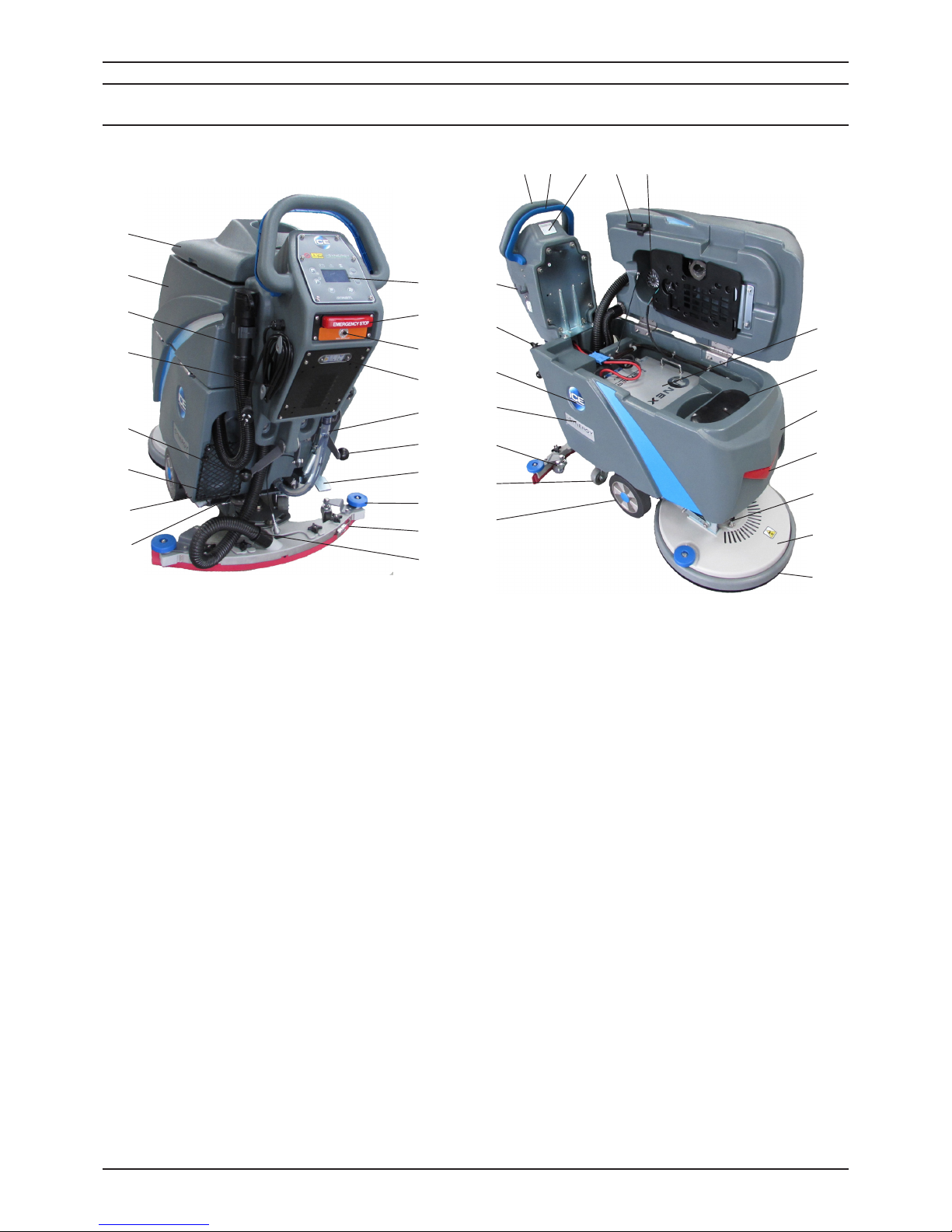
MACHINE COMPONENTS
1. Control Handle
2. Control Handle Start Bail
3. i-synergyTM, ID card scanning area
4. Recovery Tank Support Stand
5. Vacuum Motor, 24VDC
6. Lithium-ion Batteries
7. Bucket Fill Port/ Clean-Out Port
8. Solution Tank
9. LED Light
10. Motor Hub Lock Pin (Disk Models)
11. Scrub Head Assembly
12. Scrub Head Skirt
13. Wheels, 8 Inch
14. Caster, 3.15 Inch
15. Caster, 2 Inch, Squeegee Blade Adjustment
16. i-SYNERGY decal
17. ICE Logo
18. Hose Fill-Port
19. Squeegee Storage Bracket
20. Control panel (see Panel components)
21. Emergency Stop Button (Drive Models)
22. Main controller breaker
23. On-board battery charger / Window
24. Solution Tank Level / Drain Hose
25. Heavy Down Pressure Lever
26. Scrub Head Lift Pedal
27. Bumper Rollers
28. Squeegee Assembly
29. Squeegee Vacuum Hose
30. Filter Assembly
31. Ball Valve
32. Cargo Mesh Bag
33. Squeegee Lift Lever
34. Power cord, on-board Battery charger
35. Recovery Tank Drain Hose
36. Recovery Tank
37. Recovery Tank Cover
1 2 3 4 5
6
7
8
9
10
11
12
15
16
17
18
19
14
13
20
21
22
23
24
25
26
27
28
31
32
33
34
35
29
30
36
37
Page 6
6 ICE i20NBL / i20NBTL / i20NBTL-OB / i24BTL
OPERATOR MANUAL
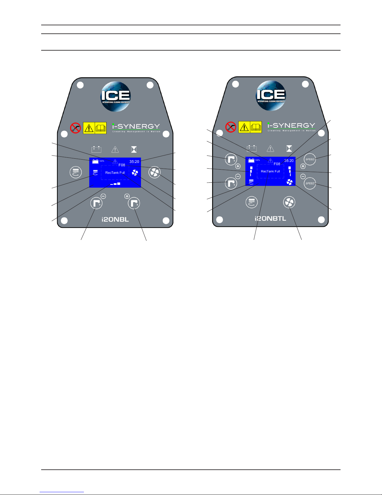
PANEL COMPONENTS
1. Fault indicator
2. Battery meter
3. Brush motor indicator
4. LED display screen
5. Solution ow indicator
6. Solution ow control button (-)
7. Solution ow control button (+)
8. Fault message display area
9. Vacuum motor indicator
10. Vacuum motor switch
11. Fault code
12. Timer
13. Speed control button (-)
14. Speed indicator
15. Speed contorl button (+)
2
3
1
5
6
7
9
10
8
11
12
2
3
1
10
13
15
9
12
11
7
5
6
8
14
4
4
Page 7
ICE i20NBL / i20NBTL / i20NBTL-OB / i24BTL 7
OPERATOR MANUAL
i-synergyTM collects operational data from
cleaning machines and transmit the information
to ICE’s server. The ICE server generates daily
reports and send them to designated end users
by email. From these reports, end users will
have information about machines’ usage and
even specic timings.
Besides, i-synergyTM also collects data on
lithium-ion battery, vacuum motor, brush
deck motor, transaxle, and other electrical
components at least once every minute when
the machine is in use and even during battery
charging.
i-synergyTM will send notications instantly
to the ICE server in case of any malfunction.
ICE maintenance personnel will receive a
SMS within minutes from the ICE server for
immediate servicing.
UNCRATING MACHINE
Be sure and check packing carton for any damage.
Immediately report any damage to carrier. Check
the contents of package to ensure that the
following items are included:
• Machine
• Lithium-ion Batteries
• Squeegee assembly
• Battery Charger
• Pad Driver
• Brush
INSTALLING BATTERIES
The machine uses the Lithium-ion batteries,
the batteries are already in the machine upon
delivery; However you will need to connect the
Lithium ion batteries to the machine.
WARNING: Fire or Explosion Hazard.
Keep sparks and open ames away! Keep
battery compartment open when charging.
1. Turn off the machine.
2. Open recovery tank to gain access to battery
compartment.
3. Carefully place the Lithium-ion batteries into the
compartment. Place the battery brace at the
rear of the batteries.
DO NOT DROP BATTERIES INTO
COMPARTMENT!
4. Plug the batteries connector to the machine
adaptor, connect machine i-synergy
TM
COM
port with the batteries.
MACHINE SET UP
PRE-OPERATION CHECKS
1. Sweep or dust mop the surface to be cleaned.
2. Check battery meter to make sure batteries are
fully charged. (See BATTERY CHARGING)
3. Check that squeegee is properly installed.
4. Check that brush / pad is properly installed.
INSTALLING PAD DRIVER OR BRUSH
1. Ensure that the machine is turned off.
2. Step down on the scrub head lift pedal (see
machine components, item #26) to raise the
scrub head off the oor.
3. If using a Pad Driver, rst attach the appropriate
pad to the pad driver surface.
4. Turn the brush motor hub until the slot with the
spring clip is visible through the scrub head
window.
5. Mount the pad driver or brush to the brush
motor hub by lining up the three studs with the
three holes in the brush motor hub. Once in the
holes, rotate the driver toward the spring clip to
lock the pad driver into place.
If necessary, press down on the motor hub lock
pin (see machine componts, item # 10)to lock
motor hub in place.
6. For Orbital head Model i20NBTL-OB, you need to
attach a rectangular, 20in(508mm)×14in(356mm)
Pad to the Orbital Pad driver. align the pad to the
Orbital pad driver, press from front-to-back and
side to side to alignment.
MOUNTING THE SQUEEGEE ASSEMBLY
1. Lift the squeegee lift lever (see machine
components, item #33)to the upward position.
2. Mount the squeegee assembly to the squeegee
pivot bracket. make sure the knobs are
completely seated into the slots before securing
knobs.
3. Connect the vacuum hose to the squeegee
assembly. Loop the hose by using the hose clip
provided.
4. Check the squeegee blades for proper
adjustment.
MACHINE SET UP & INSTALLATION
i-synergy
TM
INTRODUCTION
Page 8
8 ICE i20NBL / i20NBTL / i20NBTL-OB / i24BTL
OPERATOR MANUAL
FILLING THE SOLUTION TANK
The machine is equipped with a hose ll-port (see
machine components, item #18) at the rear of
the machine, and a bucket ll-port (see machine
components, item #7)located under the recovery
tank. Before accessing the bucket ll-port make
sure that the recovery tank is empty.
Fill the solution tank to the "60L" level on the
solution tank sight gauge. When using the bucket
ll-port, stop lling when the level reaches the
bottom edge of the ll-port.
NOTE:
When lling the solution tank with a
bucket, make sure that the bucket is clean. Do not
use the same bucket for lling and draining the
machine.
WARNING: Do not put any ammable
materials into solution tank. this can cause an
explosion or a re. Only use recommended
cleaning chemicals. Contact your janitorial
supply distributor for recommendations on
proper chemicals.
WARNING: Do not operate machine
unless you have read and understand this
manual.
1. Lower squeegee assembly to the oor by
lowering the squeegee lift lever(see machine
components, item #33).
2. Lower the scrub head to the oor by stepping
on the scrub head lift pedal(see machine
components, item #26).
3. Swiping the ID card (see machine components,
item #3) to turn on the machine.
4. Check the battery meter (see Panel
components, item #2), if the battery is very low,
there will be a Fault code & message on the
LED display screen(see Fault code section),
and the Fault indicator will blink continuously
accompany an audible alarm. please DO NOT
continue to operate the machine and recharge
the batteries immediately.
5. Check the solution ow indicator (see Panel
components, item #5), press the solution ow
control button (see Panel components, item #6,
7) to a desired ow rate.
NOTE: Solution will not begin to ow until
the control handle bail is pulled.
6. Turn on the vacuum motor switch(see Panel
components, item #10).
7. i20NBL: Pull the control handle bail(see
machine components, item #2) backwards to
start scrubbing by moving the machine forward.
The drive model i20NBTL / i24BTL: Pull the
control handle bail(see machine components,
item #2) backwards to start scrubbing. The
machine will automatically propel forward.
To reverse the drive model, simply push the
control handle bail forward. the speed can be
adjusted, Adjust the speed control button (see
Panel components, item #13, 15) to a desired
scrubbing speed.
NOTE:
45-60 meters (150-200 ft)per minute is
the recommended scrubbing speed.
8. When more brush pressure is needed for heavily
soiled areas simply lift the down pressure
lever(see machine components, item #25).
9. To stop scrubbing, release the control handle
bail, raise the scrub head and the squeegee
assembly.
WARNING: Fire Or Explosion Hazard. Do
Not Pick Up Flammable Materials Or Reactive
Metals.
1. Go slow on inclines and slippery surfaces. Do
not operate the machine on inclines that exceed
5% (3°).
2. Do not keep the machine in the same position
with pad / brush spinning, keep the machine
moving to prevent damage to oor nish.
3. If the squeegee assembly leaves streaks on the
oor, raise the squeegee off the oor and wipe
the blades down with a damp cloth. Pre-sweep
the area to prevent leaving streaks on the oor.
4. Pour a recommended defoamer into the
recovery tank if excessive foam appears.
WARNING: Do not allow foam to enter
the oat shut-off screen, vacuum motor
damage will result. Foam will not activate the
oat shut-off screen.
5. Occasionally check the battery meter(see Panel
components, item #2). when the bettery is very
low, stop scrubbing and recharge the batteries.
WARNING: When battery is very low, do
not continue to operate the machine. Battery
damage may result.
6. When the solution tank runs empty, raise the
brush head off the oor. Keep the squeegee
down and continue to vacuum until all the dirty
water is picked up.
NOTE:
See
TANK DRAINING
section to learn how
to drain recovery and solution tanks.
MACHINE OPERATION
WHILE OPERATING MACHINE
Page 9
ICE i20NBL / i20NBTL / i20NBTL-OB / i24BTL 9
OPERATOR MANUAL
CIRCUIT BREAKER
The machine is equipped with a resettable circuit
breaker(see machine components, item #22) to
protect the Main controller. If the circuit breaker
should trip, it can't be reset immediately. You must
rst determine what caused the breaker to trip, and
allow the Controller to cool down and then you can
manually reset the circuit breakers.
NOTE:
Contact an Authorized Service center for
machine repairs.
HOUR METER
The hour meter (see Panel components, item
#12) records the number of total hours the brush
motor has been powered on. Use the hour meter
to determine when to perform recommended
maintenance procedures and to record service
history.
TANK DRAINING
1. Turn the machine off.
2. With the squeegee and scrub head in their "up"
position, transport machine to approved area for
draining tank(s).
DRAINING THE RECOVERY TANK
Any time scrubbing is completed, or when relling
solution tank, the recovery tank should be drained
and cleaned.
WARNING: If the recovery tank is not
drained when the solution tank has been
relled, foam or water may enter the oat shut-
off screen and cause damage to the vacuum
motor.
1. While holding the drain hose (see machine
components, item #35) upward, remove the cap
and lower hose to drain.
2. Open the recovery tank cover and rinse out the
tank. Use a rag to remove any excess dirt.
3. Clean the oat shut-off screen and debris tray
located in the recovery tank .
DRAINING THE SOLUTION TANK
Any time scrubbing operation is completed, the
solution tank should be drained and cleaned.
1. Pull the solution tank level hose(see machine
components, item #24) off the hose tting, this
will allow the solution to ow freely into a bucket
or oor drain.
2. Remove the cover of the lter assembly(see
machine components, item #30) to drain the
solution tank, check the lter screen and clean
up it if necessary.
3. Rinse the solution tank with clean water after
every use. This will help prevent chemical
buildup and clogging of the solution lines.
4. After rinsing out the tank, securely reconnect
the tank level hose to the hose tting, replace
the lter assembly cover and be sure the
lter screen and the "O" ring is in the correct
position.
WARNING: Fire Or Explosion Hazard.
Keep Sparks and Open Flame Away. Keep
Battery Compartment Propped Open When
Charging.
Only use ICE supplied or approved batteries
charger, use unapproved charger may cause
damage to the batteries and machine.
Batteries charger specications:
• Applicable to charging Lithium-ion batteries
• Automatic shut off circuit
• Output current of 15 Amps
• Output voltage of 24 volts
1. Place machine in a well ventilated area.
2. Turn the machine off.
3. Connect the charger's AC power supply cord
(see machine components, item #34)to a
properly grounded receptable.
4. Prop up the recovery tank by the support
stand (see machine components, item #4) for
ventilation when charging.
5. The charger will automatically begin to charge
and will automatically shut off once the batteries
are fully charged.
6. Upon completion of charging, disconnect the
AC power supply cord.
BATTERY CHARGING
Page 10
10 ICE i20NBL / i20NBTL / i20NBTL-OB / i24BTL
OPERATOR MANUAL
WARNING: Before performing any
maintenance on the machine, be sure that
the power is turned off, or the batteries are
disconnected!
WARING: Repairs are to be completed
by Authorized service centers only. Any repairs
completed by unauthorized persons will avoid
the warrenty.
DAILY MAINTENANCE
1. Remove pad driver/ brush and clean with
approved cleaner.
2. Drain recovery and solution tanks completely
and rinse out with clean water. Visually check
the recovery tank for debris and clean out as
necessary.
3. Raise the squeegee assembly off oor and wipe
it down with a damp towel. Be sure to store the
squeegee in the up position.
4. Remove the oat shut-off assembly and rinse it
out with clean water.
5. Clean machine with an approved cleaner and a
damp towel.
6. Recharge the batteries.
7. Check the condition of the squeegee blade
wiping edge, rotate blade if worn.
MONTHLY MAINTENANCE
1. Clean the battery tops to prevent corrosion.
2. Check for loose battery cable connections.
3. Inspect and clean the recovery tank cover seal.
Replce it if damaged.
4. Lubricate all grease points and pivot points with
silicon spray and approved grease.
5. Check the machine for loose nuts and bolts.
6. Check the machine for leaks.
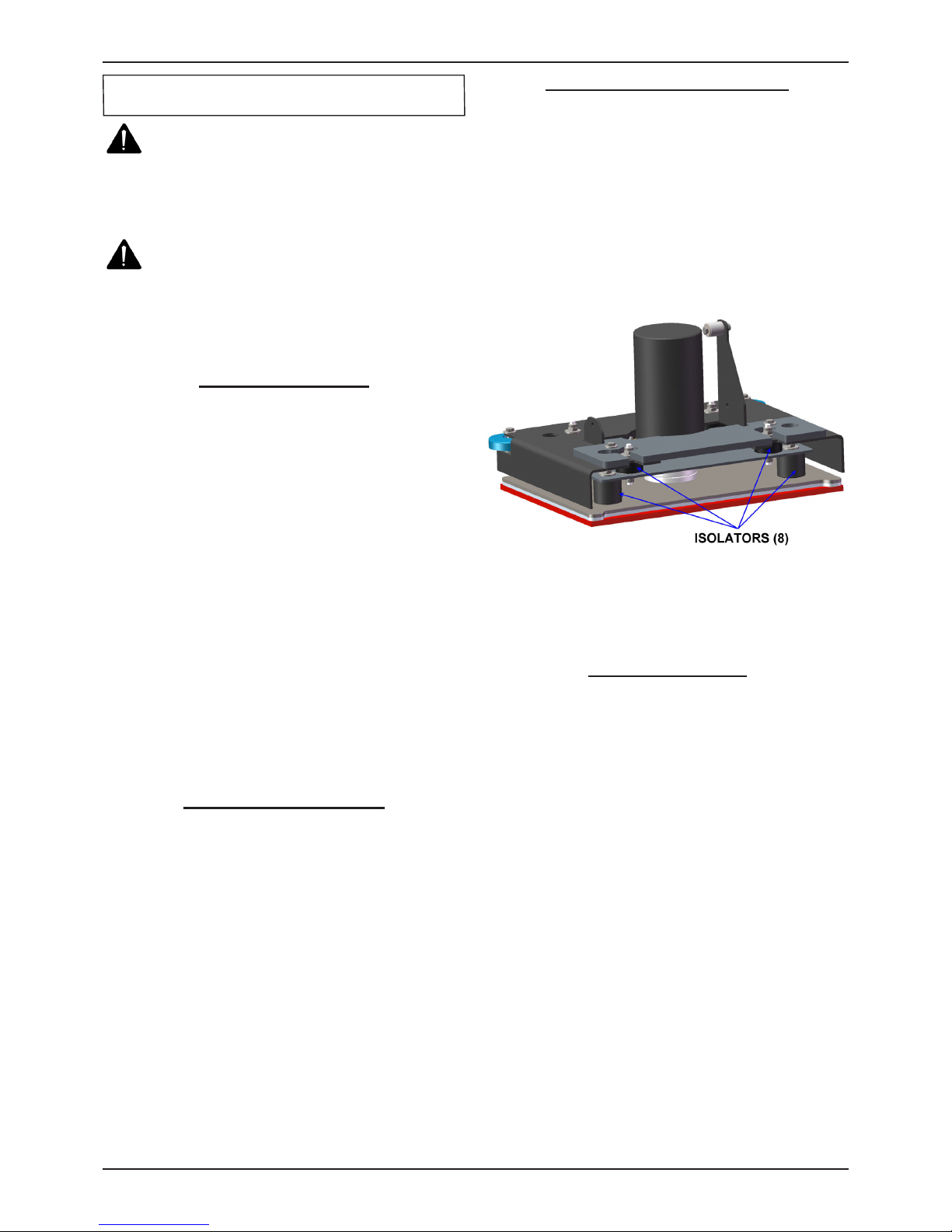
ORBITAL HEAD MAINTENANCE
For Orbital head, you should have checked the
eight isolators located in the Orbital head every 300
hours.
1. Using a ashlight, do a visual inspection of the
isolators by looking through the opening in the
Orbital head and checking for wear or damage
to four isolators in the front and four in the rear
of the Orbital head. The locations of the isolators
are show below.
2. If any of the eight isolators show signs of wear,
degradation or damage, contact your local
distributor to replace all eight isolators.
MACHINE STORAGE
1. Always store the machine indoors.
2. Always store the machine in a dry area.
3. Always store the machine in its upright position.
4. Always store the machine with the pad driver/
brush raised off the oor.
5. Always store the machine with the squeegee
assembly raised off the oor.
6. If storing in an area which may reach freezing
temperatures, be sure to drain all uids from the
machine prior to storage. Any damage caused by
freezing temperatures will not be covered by the
warranty.
7. Drain the recovery tank.
8. Drain the solution tank of all uid.
PREVENTATIVE MAINTENANCE
Page 11

ICE i20NBL / i20NBTL / i20NBTL-OB / i24BTL 11
OPERATOR MANUAL
FAULT CODE & SOLUTION
FAULT
CODE
FAULT MESSAGE
MODEL
FAULT CAUSE SOLUTION
i20NBL
i20NBTL
i24BTL
F01 Lower Brush Deck
●
Brush deck is off the oor
Release the control handle bail
Or Lower the Brush deck
F04
Vac Mtr O.L.
RE-START!
● ●
Vacuum motor overload
Turn off the machine,after a
moment, RE-START machine
F06
Bru Mtr O.L.
RE-START!
● ●
Brush motor overload
F07
Propel Mtr O.L.
RE-START!
●
Propel motor overload
F08 RecTank Full
● ●
Recovery tank is full
Or Bad Solution level sensor
Drain the Recovery tank/Replace
the solution level sensor
F10
Batt Low
Charge Batt
● ●
Battery is low Charge the battery
F11
Batt Empty
Charge Batt NOW
● ●
Battery is empty Charge the battery NOW
F12
Brake Wiring
Error
●
Bad Brake wiring
Bad Brake
Check the brake wiring
Replace the Brake assembly
F14 Replace Brake Assy
●
Bad Brake assembly Replace the brake assembly
F16
Control Unit
Overheat! Wait
● ●
Control Unit Overheat
Turn off the machine,after a
moment, RE-START machine
F17 Replace Control Unit
● ●
Control Unit Fault Replace the control unit
F21 Check Vac Mtr
● ●
Bad Vacuum motor or wiring Check the vacuum motor / Wiring
F22 Check Soln Solenoid
● ●
Solution solenoid wiring fault Check the wiring & Contactors
F23 Replace Soln solenoid
● ●
Bad Solution solenoid Replace the solution solenoid
F24 Check Propel Motor
●
Bad propel motor Check the propel motor / Wiring
F25 Check Brush Motor
● ●
Bad brush motor Check the brush motor / Wiring
F40 Check Proximity Sw
● ●
Proximity switch fault Check the Proximity switch
F41 Release Handle
● ●
Operation mistake Release the control handle bail
F42 Replace Control Unit
● ●
Bad Control Unit Replace the control unit
F43
Turn Dead Sw Off
RE-START!
●
Emergency stop button
activated.
Release emergency stop button
and restart machine.
F44 Replace Control Unit
● ●
Bad Control Unit
Contact service center, Replace
the Control Unit
F45 Return Control Unit
● ●
F46 Return Control Unit
● ●
F47 Return Control Unit
● ●
F48 Return Control Unit
● ●
The machine is equipped with a LED display
screen (see Panel components, item # 4), the LED
screen will display the operating hours (see Panel
components, item # 12) and the battery level status
(see Panel components, item # 2).
When the machine detects a fault, there will be
a Fault code (see Panel components, item #11)
& Fault message (see Panel components, item
#8) display on the LED screen, and the Fault
indicator (see Panel components, item #1) will
ash continuously, accompany an audible alarm
Occasionally.
Once fault occuring, please DO NOT continue
operate the machine unless the fault are eliminated.
Turn off the machine, then to solve the fault, the
fault code & message will be eliminated when
machine restart.
If the fault is occurred frequently, or the fault can't
be eliminated, please contact ICE service center.
Please refer to the below table to determine the
fault cause and the solution.
Page 12

12 ICE i20NBL / i20NBTL / i20NBTL-OB / i24BTL
OPERATOR MANUAL
PROBLEM CAUSE SOLUTION
Machine will not
operate
Control handle bail not pulled Pull control handle bail
Lithium-ion batteries need to be charged Charge batteries
Bad lithium-ion batteries Replace batteries
Loose batteries connection Tighten the connector
Main control unit circuit breaker tripped Reset main control unit breaker
Faulty i-synergy
TM
module Contact ICE service center
Brush motor will
not operate
Scrub head is raised off oor Lower scrub head
Faulty scrub head (up/down)switch Contact ICE service center
Faulty control handle bail switch Contact ICE service center
Faulty brush motor or wiring Contact ICE service center
Worn Motor carbon brushes Contact ICE service center
Machine does
not propel (Drive
model)
Faulty transaxle motor or wiring Contact ICE service center
Worn Motor carbon brushes Contact ICE service center
Vacuum motor
will not operate
Faulty vacuum motor or wiring Contact ICE service center
Worn Motor carbon brushes Contact ICE service center
Little or no
solution ow
Ball valve set too low or shut off Turn on the ball valve
Solution ow control knob set too low or
shut off
Adjust solution control ow knob
Clogged solution tank lter or solution
hose
Clean solution tank filter or flush out
solution hose
Clogged solution Solenoid valve Remove valve and clean
Poor water pick
up
Recovery tank is full Drain recovery tank
Loose drain hose cap Tighten cap
Clogged oat shut-off screen located in
recovery tank
clean screen
Clogged squeegee assembly Clean squeegee assembly
Worn squeegee blades Replace or rotate squeegee blades
Incorrect squeegee blade deection Adjust squeegee blade height
Loose vacuum hose connections Secure hose connections
Clogged vacuum hose Remove clogged debris
Damaged vacuum hose Replace vacuum hose
Recovery tank cover not in place Properly position cover
Damaged recovery tank cover seal Replace seal
Faulty vacuum motor Contact ICE service center
Low battery charge Recharge batteries
Short run time
Low battery charge Fully recharge batteries
Defective batteries Replace batteries
Faulty battery charger Repair or replace battery charger
Down pressure lever is set for extra scrub
head pressure
Lower down pressure lever
BASIC TROUBLESHOOTING
Page 13

ICE i20NBL / i20NBTL / i20NBTL-OB / i24BTL 13
OPERATOR MANUAL
TECHNICAL SPECIFICATIONS
MODEL
i20NBL
Brush Assist
i20NBTL
W/ Drive
i20NBTL-OB
Orbital head
i24BTL
Dual disk
DIMENSIONS L
55.7 in / 1,415 mm 53.5 in / 1,360 mm 52.2 in / 1,325 mm
DIMENSIONS W
22 in / 560 mm 22 in / 560 mm 25.6 in / 650 mm
DIMENSIONS H
44.9 in / 1,140 mm 44.9 in / 1,140 mm 44.9 in / 1,140 mm
WEIGHT
210 lbs / 95 Kg 230 lbs / 105 Kg
WEIGHT with BATTERIES
310 lbs /140 Kg 330 lbs / 150 Kg
RECOVERY TANK
CAPACITY
17.2 Gal / 65 L
SOLUTION TANK
CAPACITY
15.9 Gal / 60 L
SQUEEGEE WIDTH
30 in / 762 mm
CLEANING PATH WIDTH
20 in / 500 mm (Disk)
500 mm / 20 in
(20 in x 14 in Pad)
24 in / 600mm
PRODUCTIVITY RATE
19,375 ft2 /
1,800 m2 h
23,680 ft2 / 2,200 m2 h
28,000 ft2 /
2,600m2 h
DRIVE SYSTEM
Brush Assisted Transaxle, 0.27 hp / 0.2KW
TRAVEL SPEED,
MAXIMUM
N/A
246 ft / Min
75 m / Min
MINIMUM AISLE TURN
63 in / 1,600 mm
PAD/BRUSH PRESSURE
65 lbs / 30 Kg Min
100 lbs / 45 Kg Max
SOLUTION FLOW RATE
0 ~ 0.37 Gal / Min
0 ~ 1,400 ml / Min
BRUSH MOTOR
0.75hp / 0.55KW
220 RPM
0.75hp / 0.55KW
2,200RPM
0.9hp / 0.68KW
2,000RPM
VIBRATIONS @
CONTROLS
N/A
< 2.5 m / s
2
< 8.2 ft / s
2
N/A
VACUUM MOTOR
0.7hp / 0.5KW
WATER LIFT - AIR FLOW
45 in / 1,143 mm
BATTERIES
Lithium-ion batteries, 120AH
RUN TIME PER CHARGE
3.5 Hours 3 Hours
VOLTAGE DC
24V
DECIBEL RATE AT
OPERATOR'S EAR,
INDOORS
68dB(A) <70dB(A) 68dB(A)
GRADE LEVEL, MAX
5% (3°)
Page 14
14
ICE i20NBL / i20NBTL / i20NBTL-OB / i24BTL
PARTS LIST
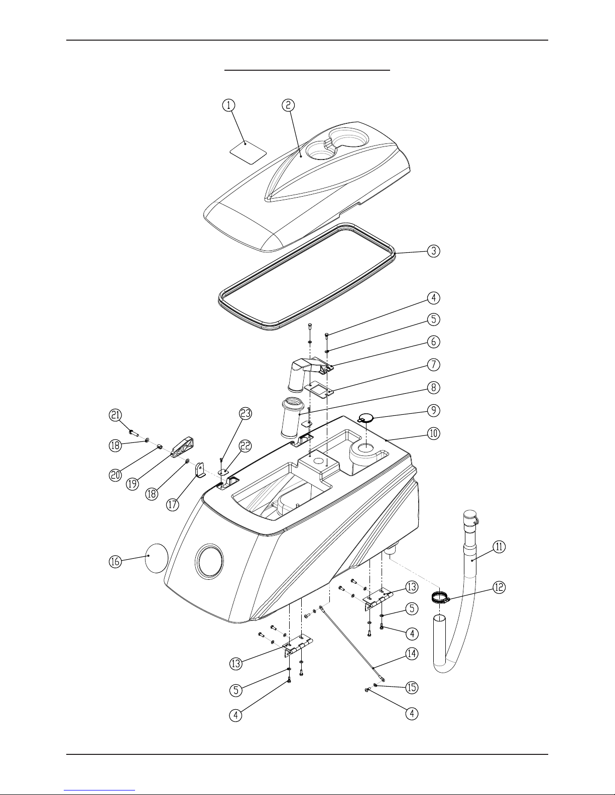
RECOVERY TANK GROUP
Page 15

ICE i20NBL / i20NBTL / i20NBTL-OB / i24BTL
15
PARTS LIST
RECOVERY TANK GROUP
DIA
NO.
PART
NUMBER
DESCRIPTION
NO
REQ'D
1 8111022 WARNING LABEL 1
2 8131002 RECOVERY TANK COVER 1
3 8131005 RECOVERY TANK COVER SEAL 1
4 1021616 HEX BOLT M6 X 16 12
5 1421618 FLAT WASHER M6×∮18×1.6 10
6 8111014 FLOAT ADAPTER 1
7 8111001 GASKET 1
8 8111015 FLOAT, SHUT-OFF 1
9 8131003 CAP 1
10 8131001 RECOVERY TANK 1
11 8131010 DRAIN HOSE 1
12 1962050 CLAMP 1
13 8111300 HINGE ASSEMBLY 2
14 8131020 CABLE 1
15 1421612 FLAT WASHER M6×∮12×1.6 2
16 4010316 ICE LOGO 1
17 8111008 BRACKET 1
18 1421816 FLAT WASHER M8×∮16×1.6 2
19 8111007 RECOVERY TANK SUPPORT 1
20 8115404 SLEEVE, P/M 1
21 1021830 HEX BOLT M8×30 1
22 8111016 PLATE 2
23 1221412 SCREW M4×12 2
Page 16

16
ICE i20NBL / i20NBTL / i20NBTL-OB / i24BTL
PARTS LIST
VACUUM FAN GROUP
Page 17

ICE i20NBL / i20NBTL / i20NBTL-OB / i24BTL
17
PARTS LIST
VACUUM FAN GROUP
DIA
NO.
PART
NUMBER
DESCRIPTION
NO
REQ'D
1 8112005 GASKET, VACUUM MOTOR 1
2 1121605 HEX NUT M6 3
3 8112006 STUD M6×92 3
4 8132050 AMETEK VACUUM MOTOR , KIT, 24VDC 1
5 1421612 FLAT WASHER M6×∮12×1.6 7
6 1123608 LOCK NUT M6 3
7 8112003 BRACKET 1
8 1021616 HEX BOLT M6×16 4
9 8132007 MUFFLER, VACUUM MOTOR 1
10 1914300 TIE, NYLON, 5X300 2
11 8112001 CHARGER COVER 1
12 8118003 KNOB M8 1
13 8112004 BRACKET 1
Page 18

18
ICE i20NBL / i20NBTL / i20NBTL-OB / i24BTL
PARTS LIST
SOLUTION TANK GROUP
Page 19

ICE i20NBL / i20NBTL / i20NBTL-OB / i24BTL
19
PARTS LIST
SOLUTION TANK GROUP
DIA
NO.
PART
NUMBER
DESCRIPTION
NO
REQ'D
1 8113115 DOWN PRESSURE LABEL 1
2 8113101 DOWN PRESSURE LEVER BRACKET 1
3 1421816 FLAT WASHER M8×∮16×1.6 2
4 1422821 LOCK WASHER M8 2
5 1021820 HEX BOLT M8×20 2
6 8113104 BALL KNOB 1
7 8113106 DOWN PRESSURE LEVER 1
8 8113112 BUSHING 1
9 8113110 SLEEVE, P/M 1
10 8113111 NYLON FLAT WASHER ∮12.9×∮25.4×0.8 2
11 8113109 THRUST BEARING 2
12 8113114 SPRING 1
13 8113107 RETAINER, SPRING 1
14 8113103 BOLT M6×18 1
15
8113108 LINK, SPRING 2
8133108 LINK, SPRING, ORBITAL HEAD MODEL 2
16 1123608 LOCK NUT M6 1
17 1221512 SCREW M5×12 15
18 1123507 LOCK NUT M5 1
19 8133113 SPRING 1
20 8133501 CARGO NET 1
21 8133502 CLAMP 4
22 1221412 SCREW M4X12 4
23 8133003 CLEAN TUBING 1
24 1962025 CLAMP 16-25mm 1
25 8130099 i-SYNERGY DECAL 2
26 8133001 SOLUTION TANK 1
27 8119005 BALL VALVE, G1/2 1
28 8119007 ELBOW G1/2 1
29 8134750 CONNECTOR, GRID, BLUE 2
30 8113013 SPACER, BATTERY 2
31 9324101 LITHIUMS-ION BATTERIES, 110AH 1
32 1421510 FLAT WASHER M5×∮10×1 17
33 8119100 FILTER ASSEMBLY 1
34 8133025 LABEL, LEFT SIDE 1
Page 20

20
ICE i20NBL / i20NBTL / i20NBTL-OB / i24BTL
PARTS LIST
SOLUTION TANK GROUP
DIA
NO.
PART
NUMBER
DESCRIPTION
NO
REQ'D
35 1321110 SELF-TAPPING SCREW ST3.5 ×10 4
36 1421409 FLAT WASHER M4×∮9×0.8 5
37 8133610 LED LIGHT, KIT 1
38 8133601
LED LIGHT MNTG BASE
1
39 1221520 SCREW M5X20 3
40 8133602 LED LIGHT COVER 1
41 8113030 SEAL 1
42 8113002 COVER 1
43 8113007 STRAP 1
44 1321213 SELF-TAPPING SCREW ST4.2X13 1
45 4010316 ICE Logo 2
46 8133026 LABEL, RIGHT SIDE 1
47 1123305 LOCK NUT M3 2
48 8113010 BRACKET, CONNECTOR MTG 1
49 1434300 LOCK WASHER, TOOTH, M3 2
50 1211325 SCREW M3×25 2
51 1422513 LOCK WASHER M5 2
52 8133002 CAP, SOLUTION FILL 1
53 8113009 NYLON, CLAMP 9
Page 21

ICE i20NBL / i20NBTL / i20NBTL-OB / i24BTL
21
PARTS LIST
CONTROL CONSOLE GROUP(i20NBL)
Page 22

22
ICE i20NBL / i20NBTL / i20NBTL-OB / i24BTL
PARTS LIST
CONTROL CONSOLE GROUP(i20NBL)
DIA
NO.
PART
NUMBER
DESCRIPTION
NO
REQ'D
1 1221512 SCREW M5×12 21
2 1422513 LOCK WASHER M5 6
3 1421510 FLAT WASHER M5×∮10×1.0 13
4 8134725 CONTROL PANEL DECAL, i20NBL 1
5 8134721 CONTROL PANEL, i20NBL 1
6 8134015 GASKET 1
7 8134723 CONTROL PANEL PCB, i20NBL 1
8 1221306 SCREW M3×6 7
9 8134005 CONTROL HOUSING 1
10 1021616 HEX BOLT M6 X 16 5
11 1421618 PLAIN WASHER M6×∮18×1.6,SS 10
12 8114008 BRACKET, SQGE STORAGE 1
13 8310740 CIRCUIT BREAKER, 5A 1
14 8134006 PLATE, CIRCUIT BREAKERS MNTG 1
15 8144025 LABEL, CIRCUIT BREAKER 1
16 1221515 PH SCREW M5×15 4
17 1123507 LOCK NUT M5 6
18 1123305 LOCK NUT M3 4
19 8113010 BRACKET, CONNECTOR MTG 1
20 8134750 CONNECTOR, GRID, BLUE 1
21 1434300 LOCK WASHER, TOOTH, M3 4
22 1211325 SCREW M3×25 2
23 8134060 PLATE, ON BOARD BATTERY CHARGER 1
24 8134061 CLEAR COVER 1
25
8134600-US
ON BOARD BATTERY CHARGER,KIT 1
26 8112030A BATTERY CHARGER POWER CORD, KIT 1
27 8134610A ON BOARD BATTERY CHARGER, 110VAC 1
28 8134062 CLAMP, BATTERY CHARGER 2
29 8114005 CONNECTOR 1
30 1021840 HEX BOLT M8×40 2
31 1422821 LOCK WASHER M8 12
32 1421828 FLAT WASHER M8×∮28×3 2
33 1021630 HEX HEAD BOLT M6×30,SS 1
34 8134082 CABLE, SQGE LIFT 1
35 8014101 LIFTING ROPE SPACER 1
36 1021512 HEX HEAD BOLT M5×12,SS 1
Page 23

ICE i20NBL / i20NBTL / i20NBTL-OB / i24BTL
23
PARTS LIST
CONTROL CONSOLE GROUP
DIA
NO.
PART
NUMBER
DESCRIPTION
NO
REQ'D
37 1421515 FLAT WASHER M5×∮15×1.0 1
38 1123608 LOCK NUT M6 3
39 8014012 BAFFLE 1
40 8113111 NYLON FLAT WASHER ∮12.9×∮25.4×0.8 1
41 1121605 HEX NUT M6 2
42 8134501 BRACKET 1
43 8134081 SLEEVEE 1
44 1421132 FLAT WASHER M12×∮32×1.5 1
45 8134080 SQUEEGEE LIFTING HANDLE 1
46 8113104 BALL KNOB M8 1
47 1222641 SUNK HEAD SCREW M6 X 40 2
48 8210112 HOOK, POWER CORD 2
49 8014054 STRAIN RELIEF 1
50 6210111 CLAMP, DRAIN HOSE 1
51 1023612 HEX BOLT M6 X 12, COPPER 6
52 1422616 LOCK WASHER, M6 11
53 1423612 FLAT WASHER M6× ∮12×1, COPPER 6
54 8134790 MAIN CONTROLLER, i20NB 1
55 8134070 REAR PLATE, CONTROL CONSOLE 1
56 1421824 FLAT WASHER M8× ∮24×2 10
57 1021820 HEX BOLT M8×20 10
58 1221620 PH SCREW M6 X 20 2
59 8134768 RFID BOARD 1
60 8134035 LABEL, i-SYNERGYTM CARD SCANNING 1
61 8114712 MICRO SWITCH 1
62 1021320 SCREW M3 X 20 2
63 8134022 BRACKET,SWITCH 1
64 8114402 BRACKET, SPRING 1
65 1521616 SCREW M6X16, HEX SCOKET 2
66 1534608 SET SCREW M6 ×8 4
67 8134300 LEVER, BAIL 1
68 8114300 ACTUATOR 1
69 8114306 SPRING 1
70 1535630 SET SCREW M6 ×30 1
71 8114101 SHAFT 1
Page 24

24
ICE i20NBL / i20NBTL / i20NBTL-OB / i24BTL
PARTS LIST
CONTROL CONSOLE GROUP (i20NBTL/i24BTL)
Page 25

ICE i20NBL / i20NBTL / i20NBTL-OB / i24BTL
25
PARTS LIST
CONTROL CONSOLE GROUP(i20NBTL/i24BTL)
DIA
NO.
PART
NUMBER
DESCRIPTION
NO
REQ'D
1 1221512 SCREW M5×12 21
2 1422513 LOCK WASHER M5 6
3 1421510 FLAT WASHER M5×∮10×1.0 13
4
8144726 CONTROL PANEL DECAL, i20NBTL 1
8144727 CONTROL PANEL DECAL, i24BTL
1
5 8144721 CONTROL PANEL, i20NBTL 1
6 8134015 GASKET 1
7 8144792 CONTROL PANEL PCB, i20NBTL 1
8 1221306 SCREW M3×6 7
9 8134005 CONTROL HOUSING 1
10 1021616 HEX BOLT M6 X 16 5
11 1421618 PLAIN WASHER M6×∮18×1.6,SS 10
12 8114008 BRACKET, SQGE STORAGE 1
13 8310740 CIRCUIT BREAKER, 5A 1
14 1221421 SCREW M4×20 2
15 1421409 FLAT WASHER M4×∮9×0.8 2
16 8124715A EMERGENCY STOP SWITCH, KIT 1
17 8144030 BASE, CIRCUIT BREAKERS MNTG 1
18 8124008 SPRING 2
19 8124716 LED LIGHT 1
20 8124007 BUTTON,EMERGENCY STOP 1
21 8124710 EMERGENCY STOP SWITCH KIT 1
22 8144025 LABEL, CIRCUIT BREAKER 1
23 1221515 PH SCREW M5×15 4
24 1123507 LOCK NUT M5 6
25 1123305 LOCK NUT M3 6
26 8113010 BRACKET, CONNECTOR MTG 1
27 8134750 CONNECTOR, GRID, BLUE 1
28 1434300 LOCK WASHER, TOOTH, M3 6
29 1211325 SCREW M3×25 2
30 8134060 PLATE, ON BOARD BATTERY CHARGER 1
31 8134061 CLEAR COVER 1
32
8134600-US
ON BOARD BATTERY CHARGER,KIT 1
33 8112030A BATTERY CHARGER POWER CORD, KIT 1
34 8134610A ON BOARD BATTERY CHARGER, 110VAC 1
35 8134062 CLAMP, BATTERY CHARGER 2
36 8114005 CONNECTOR 1
37 1021840 HEX BOLT M8×40 2
38 1422821 LOCK WASHER M8 12
39 1421828 FLAT WASHER M8×∮28×3 2
40 1021630 HEX HEAD BOLT M6×30,SS 1
Page 26

26
ICE i20NBL / i20NBTL / i20NBTL-OB / i24BTL
PARTS LIST
CONTROL CONSOLE GROUP(i20NBTL/i24BTL)
DIA
NO.
PART
NUMBER
DESCRIPTION
NO
REQ'D
41 8134082 CABLE, SQGE LIFT 1
42 8014101 LIFTING ROPE SPACER 1
43 1021512 HEX HEAD BOLT M5×12,SS 1
44 1421515 FLAT WASHER M5×∮15×1.0 1
45 1123608 LOCK NUT M6 3
46 8014012 BAFFLE 1
47 8113111 NYLON FLAT WASHER ∮12.9×∮25.4×0.8 1
48 1121605 HEX NUT M6 2
49 8134501 BRACKET 1
50 8134081 SLEEVEE 1
51 1421132 FLAT WASHER M12×∮32×1.5 1
52 8134080 SQUEEGEE LIFTING HANDLE 1
53 8113104 BALL KNOB M8 1
54 1222641 SUNK HEAD SCREW M6 X 40 2
55 8210112 HOOK, POWER CORD 2
56 8014054 STRAIN RELIEF 1
57 6210111 CLAMP, DRAIN HOSE 1
58 1023612 HEX BOLT M6 X 12, COPPER 8
59 1422616 LOCK WASHER, M6 13
60 1423612 FLAT WASHER M6× ∮12×1, COPPER 8
61 8144790 MAIN CONTROLLER, i20NBT 1
62 8134070 REAR PLATE, CONTROL CONSOLE 1
63 1421824 FLAT WASHER M8× ∮24×2 10
64 1021820 HEX BOLT M8×20 10
65 1221620 PH SCREW M6×20 2
66 8134768 RFID BOARD 1
67 8134035 LABEL, i-SYNERGYTM CARD SCANNING 1
68 8114712 MICRO SWITCH 1
69 8124743 MICRO SWITCH 1
70 1021320 SCREW M3 X 20 4
71 8134022 BRACKET,SWITCH 1
72 8114402 BRACKET, SPRING 1
73 1521616 SCREW M6X16, HEX SCOKET 2
74 1534608 SET SCREW M6 ×8 4
75 8134300 LEVER, BAIL 1
76 8114300 ACTUATOR 1
77 8114306 SPRING 1
78 1535630 SET SCREW M6 ×30 1
79 8114101 SHAFT 1
Page 27

ICE i20NBL / i20NBTL / i20NBTL-OB / i24BTL
27
PARTS LIST
FRAME & WHEEL GROUP(i20NBL)
Page 28

28
ICE i20NBL / i20NBTL / i20NBTL-OB / i24BTL
PARTS LIST
FRAME & WHEEL GROUP(i20NBL)
DIA
NO.
PART
NUMBER
DESCRIPTION
NO
REQ'D
1 1021820 HEX BOLT M8×20 12
2 1422821 LOCK WASHER M8 7
3 1421824 FLAT WASHER M8×∮24×2 5
4 8145100 MAIN FRAME 1
5 1421618 FLAT WASHER M6×∮18×1.6 4
6 1123608 LOCK NUT M6 3
7 8115300 BRACKET, PEDAL LOCKING 1
8 1421124 FLAT WASHER M12×∮24×2.5 4
9 1123115 LOCK NUT M12 4
10 8119003 SOLENOID VALVE, 24VDC 1
11 1421409 FLAT WASHER M4×∮9×0.8 2
12 1422411 LOCK WASHER M4 2
13 1221412 SCREW M4×12 4
14 8115004 SPIRNG 1
15 8135010 BRACKET, SQGE LIFT 1
16 8115405 SLEEVE, P/M 4
17 8135001 PLASTIC THRUST WASHER M12×∮ 30×1.5 4
18 1421132 FLAT WASHER M12×∮32×1.5 4
19 1021230 HEX BOLT M12 ×30 2
20 1645324 COTTER 3.2 ×24 1
21 8115003 PIN 1
22 8114511 BALL JOINT M6 1
23 8115001 BRACKET, SQGE MNTG 1
24 8115203 COVER, WHEEL 2
25 1021816 HEX BOLT M8×16 3
26 1421828 FLAT WASHER M8×∮28×3 2
27 8115200 WHEEL, 8 INCH 2
28 1421816 FLAT WASHER M8×∮16×1.6 10
29 8135405 SHAFT 1
30 1123810 LOCK NUT M8 10
31 8117007 NYLON WASHER ∮12.9×∮24×2.5 4
32 8115404 BEARING, JOURNAL 2
33 8145001 BUSHING 2
34 1021840 HEX BOLT M8 ×40 2
35 1211325 SCREW M3×25 2
36 1434300 LOCK WASHER, TOOTH, M3 2
37 8014071 MICRO SWITCH 20A 1
38 8115500 CASTER, SWIVEL, 80MM 2
39 8210118 STATIC STRAP 1
40 8134709A PROXIMITY SENSOR, KIT 1
Page 29

ICE i20NBL / i20NBTL / i20NBTL-OB / i24BTL
29
PARTS LIST
FRAME & TRANSAXLE GROUP(i20NBTL/i24BTL)
Page 30

30
ICE i20NBL / i20NBTL / i20NBTL-OB / i24BTL
PARTS LIST
FRAME & TRANSAXLE GROUP(i20NBTL/i24BTL)
DIA
NO.
PART
NUMBER
DESCRIPTION
NO
REQ'D
1 1021820 HEX BOLT M8×20 12
2 1422821 LOCK WASHER M8 15
3 1421824 FLAT WASHER M8×∮24×2 5
4 8145100 MAIN FRAME 1
5 1421618 FLAT WASHER M6×∮18×1.6 4
6 1123608 LOCK NUT M6 3
7 8115300 BRACKET, PEDAL LOCKING 1
8 1421124 FLAT WASHER M12×∮24×2.5 4
9 1123115 LOCK NUT M12 4
10 8119003 SOLENOID VALVE, 24VDC 1
11 1421409 FLAT WASHER M4×∮9×0.8 2
12 1422411 LOCK WASHER M4 2
13 1221412 SCREW M4×12 4
14 8115004 SPIRNG 1
15 8135010 BRACKET, SQGE LIFT 1
16 8115405 SLEEVE, P/M 4
17 8135001 PLASTIC THRUST WASHER M12×∮ 30×1.5 4
18 1421132 FLAT WASHER M12×∮32×1.5 4
19 1021230 HEX BOLT M12 ×30 2
20 1645324 COTTER 3.2 ×24 1
21 8115003 PIN 1
22 8114511 BALL JOINT M6 1
23 8115001 BRACKET, SQGE MNTG 1
24 8115203 COVER, WHEEL 2
25 1021816 HEX BOLT M8×16 3
26 1421828 FLAT WASHER M8×∮28×3 2
27
8125200 WHEEL, 8 INCH 2
8225200 AIR FILLED WHEEL, 8 INCH, KIT 2
8225210 FOAM FILLED WHEEL, 8INCH, KIT 2
28 1421816 FLAT WASHER M8×∮16×1.6 10
29 1436019 RETAINING RING 19 2
30 8125403 WOODRUFF KEY 2
31 8125410 TRANSAXLE, KIT 1
32 1123810 LOCK NUT M8 10
33 8117007 NYLON WASHER ∮12.9×∮24×2.5 4
34 8115404 BEARING, JOURNAL 2
35 8145001 BUSHING 2
36 1021840 HEX BOLT M8 ×40 2
37 1211325 SCREW M3×25 2
38 1434300 LOCK WASHER, TOOTH, M3 2
39 8014071 MICRO SWITCH 20A 1
40 8115500 CASTER, SWIVEL, 80MM 2
41 8210118 STATIC STRAP 1
42 8134709A PROXIMITY SENSOR, KIT 1
Page 31

ICE i20NBL / i20NBTL / i20NBTL-OB / i24BTL
31
PARTS LIST
SCRUB HEAD GROUP (i20NBL / i20NBTL)
Page 32

32
ICE i20NBL / i20NBTL / i20NBTL-OB / i24BTL
PARTS LIST
SCRUB HEAD GROUP (i20NBL / i20NBTL)
DIA
NO.
PART
NUMBER
DESCRIPTION
NO
REQ'D
1 8116200 BRUSH MOTOR, 24VDC 1.0HP, KIT 1
2 1656432 KEY 1
3 1221412 SCREW M4×12 1
4 1422513 LOCK WASHER M5 3
5 1421518 FLAT WASHER M5×∮18×2 1
6 8116100 WATER SUPPLY TUBE 1
7 8116006 SCRUB HEAD HOUSING 1
8 8116020 BUMPER, SCRUB HEAD 1
9 8116001 SPACER 2
10 8116008 HUB, DRIVE, 3 LUG 1
11 1221512 SCREW M5×12 2
12 1421510 FLAT WASHER M5×∮10×1 2
13 8116002 BRUSH CLAMP PLATE 1
14 8116003 SPRING CLIP 1
15 8116010 FLAT WASHER ∮8.5×∮25.4×4.5 1
16 1422821 LOCK WASHER M8 2
17 1023815 HEX BOLT 5/16-18 ×1.5" UNC 1
18 1222635 SCREW, M6X35 6
19 8116030 STUD 6
20
9040019 19" PAD DRIVER 1
9040019K 19" PAD DRIVER (OPTIONAL) 1
21
9000001 BIG MOUTH 1
9000003 CENTER-LOK 3 (OPTIONAL) 1
22 1321325 SELF-TAPPING SCREW, ST4.8X25 3
23 8116040 SPACER 3
24
9050020 20" BRUSH, 0.7mm PP BRISTLE 1
9050020E 20" BRUSH, 0.5mm PP BRISTLE (OPTIOAL) 1
25 1023010 HEX BOLT 3/8-16 ×1" UNC 4
26 1422026 LOCK WASHER M10 4
27 1421030 FLAT WASHER M10×∮30×2.5 4
28 8116202 PIN 1
29 8116205 SCREW M14 × 20 1
30 8111023 WARNING LABEL 1
31 1121913 HEX NUT M14 1
32 8116204 SRPING 1
33 8116210 KNOB M6 1
34 8116009 PROTECTIVE WHEEL 1
35 8115404 SLEEVE, P/M 1
36 1421824 FLAT WASHER M8×∮24×2.0 1
37 1021825 HEX BOLT M8×25 1
Page 33

ICE i20NBL / i20NBTL / i20NBTL-OB / i24BTL
33
PARTS LIST
ORBITAL HEAD GROUP (i20NBTL-OB)
Page 34

34
ICE i20NBL / i20NBTL / i20NBTL-OB / i24BTL
PARTS LIST
ORBITAL HEAD GROUP (i20NBTL-OB)
DIA
NO.
PART
NUMBER
DESCRIPTION
NO
REQ'D
1 1123012 LOCK NUT, M10 12
2 1421030 FLAT WASHER M10×∮30×2.5 16
3 1022845 HEX BOLT M8×45 2
4 1421824 FLAT WASHER M8×∮24×2.0 6
5 8146101 BRACKET, ORBITAL HEAD 1
6 8115404 BEARING, JOURNAL 4
7 1435013 WAVE WASHER 2
8 8116009 PROTECTIVE WHEEL 2
9 1123810 LOCK NUT, M8 2
10 1421510 FLAT WASHER M5×∮10×1.0 4
11 1221515 SCREW M5×15 2
12 8146116 ISOLATORS, M10×25 4
13 8146199 MOTOR, 24VDC 550W 2200RPM, KIT 1
14 8146110 KEY, 8×7×28 1
15 8146102 BRACKET, MOTOR MOUNTING 1
16 1513620 HEX SOCKET SCREW, M6×20 4
17 1513616 HEX SOCKET SCREW, M6×16 4
18 8146202 ECCENTRIC 1
19 8146107 ISOLATORS, M10×25 4
20 8146201 ECCENTRIC SHAFT 1
21 1535610 SET SCREW, M6×10 1
22 8146204 BEARING HOUSING 1
23 1612608 BALL BEAING 6008 1
24 8146203 BEARING HOUSING 1
25 1521616 HEX SOCKET BOLT M6×16 2
26 8146103 PAD DRIVER 1
27 1513020 HEX SOCKET SCREW, M10×20 4
28 1513625 HEX SOCKET SCREW, M6×25 4
29 8146205 PLATE 1
30 8146303 END CAP 3/8 2
31 8146302 PVC TUBING 2
32 8146305 PLASTIC CLAMP 2
33 1123507 LOCK NUT M5 2
34 8146301 TEE FITTING 3/8 1
35 8013007 TUBING FITTING 1
36 8146350 TUBING, ID=12mm, WIRE REINFORCED 1
37 1962016 CLAMP 2
38 8119012 TUBING FITTING 1
Page 35

ICE i20NBL / i20NBTL / i20NBTL-OB / i24BTL
35
PARTS LIST
SCRUB HEAD GROUP (i24BTL)
Page 36

36
ICE i20NBL / i20NBTL / i20NBTL-OB / i24BTL
PARTS LIST
SCRUB HEAD GROUP (i24BTL)
DIA
NO.
PART
NUMBER
DESCRIPTION
NO
REQ'D
1 8126200 BRUSH MOTOR, 24VDC 680W 2000RPM, KIT 1
2 8126006 SHEAVE, SS 1
3 1534508 SCREW, SET, M5X8 2
4 1655025 KEY, 5X5X25 1
5 1421612 FLAT WASHER M6×∮12×1.6 7
6 1422616 LOCK WASHER, M6 7
7 1021616 HEX BOLT M6×16 12
8 8119301 TUBING, ID=6mm, L=250mm 2
9 8126007 BRACKET, GUIDE, BELT 1
10 8126002 SCRUB HEAD HOUSING 1
11 8126050 BUMPER, SCRUB HEAD 2
12 8126040 SHAFT, PULLY 2
13 1612203 BEARING, 6203RS 7
14 8126008 BUSHING 2
15 8126005 BELT, 6PJ1598 1
16 1221512 SCREW M5×12 8
17 1422513 LOCK WASHER M5 8
18 1421510 FLAT WASHER M5×∮10×1 8
19 8116002 BRUSH CLAMP PLATE 2
20 8116003 SPRING CLIP 2
21 8126009 PLATE, CLAMP, BRUSH 2
22 8126004 HUB, DRIVER, 3LUG, PULLY 1
23 1421124 FLAT WASHER M12×∮24×2.5 4
24 1123115 LOCK NUT M12 4
25 8126020 BRACKET, GUARD, SPLASH 1
26
9040011 11" PAD DRIVER 2
9040011K 11" PAD DRIVER (OPTIONAL) 2
27 1222635 SCREW, M6X35 12
28 8116030 STUD 12
29
9000001 BIG MOUTH 2
9000003 CENTER-LOK 3 (OPTIONAL) 2
30 1321325 SELF-TAPPING SCREW, ST4.8X25 6
31 8116040 SPACER 6
32 9050012 12" BRUSH 2
33 8126032 SPACER, IDLER 3
34 8126031 PULLEY, IDLER 3
35 1437040 RING, RETAINING, 40 3
36 8126003 HUB, DRIVE, 3LUG, 6GRV 1
37 8111023 WARNING LABEL 1
38 1021820 HEX BOLT M8×20 3
39 1123810 LOCK NUT M8 1
40 8126012 BRACKET, WALL-ROLLER 1
41 8119004 FITTING, PLASTIC, TEE 1
42 1962016 CLAMP, 10-16mm 1
43 1914300 TIE, NYLON, 5X300 2
44 8116009 PROTECTIVE WHEEL 1
45 8115404 SLEEVE, P/M 1
46 1421824 FLAT WASHER M8×∮24×2.0 1
47 1021825 HEX BOLT M8×25 1
48 8126202 PIN 1
49 8126205 GUIDE, M14X20 1
50 1421428 FLAT WASHER M14×∮28×2.0 1
51 1121913 NUT M14 1
52 8116204 SPRING 1
53 8116210 KNOB M6 1
Page 37

ICE i20NBL / i20NBTL / i20NBTL-OB / i24BTL
37
PARTS LIST
SCRUB HEAD LIFT GROUP (i20NBL / i20NBTL)
Page 38

38
ICE i20NBL / i20NBTL / i20NBTL-OB / i24BTL
PARTS LIST
SCRUB HEAD LIFT GROUP (i20NBL / i20NBTL)
DIA
NO.
PART
NUMBER
DESCRIPTION
NO
REQ'D
1 8137006 NON-SLIP MAT 1
2 8137100 BRACKET, SCRUB HEAD LIFT 1
3 8133151 BUMPER 1
4 1123810 LOCK NUT M8 5
5 1021830 HEX BOLT M8×30 2
6 1421824 FLAT WASHER M8×∮24×2 6
7 8117007 NYLON WASHER ∮12.9×∮24×2.5 4
8 8115404 BEARING, JOURNAL 7
9 8115405 SLEEVE, P/M 2
10 1021825 HEX BOLT M8×25 4
11 1422821 LOCK WASHER M8 4
12 1421816 FLAT WASHER M8×∮16×1.6 4
13 8117002 LEFT BRACKET 1
14 8117005 SPACER(i20NB) 1
15 8117003 RIGHT BRACKET 1
16 1022860 HEX BOLT M8 ×60 1
17 8117008 SPRING 1
18 8113109 BEARING, THRUST 2
19 1022845 HEX BOLT M8 ×45 1
20 8117004 ROLLER 1
21 1421612 FLAT WASHER M6×∮12×1.6 2
22 1422616 LOCK WASHER M6 2
23 1021616 HEX BOLT M6 ×16 2
24 8117009 SPRING 1
25 8117001 BRACKET, GUIDE 1
Page 39

ICE i20NBL / i20NBTL / i20NBTL-OB / i24BTL
39
PARTS LIST
ORBITAL HEAD LIFT GROUP (i20NBTL-OB)
Page 40

40
ICE i20NBL / i20NBTL / i20NBTL-OB / i24BTL
PARTS LIST
DIA
NO.
PART
NUMBER
DESCRIPTION
NO
REQ'D
1 8137006 NON-SLIP MAT 1
2 8137100 BRACKET, SCRUB HEAD LIFT 1
3 8133151 BUMPER 1
4 1123810 LOCK NUT M8 5
5 1021830 HEX HEAD BOLT M8×30 2
6 1421824 FLAT WASHER M8×∮24×2 8
7 8117007 NYLON WASHER ∮12.9×∮24×2.5 4
8 1435013 WAVE WASHER 10
9
8115404 BEARING, JOURNAL 4
10
8115405 SLEEVE, P/M 2
11
1022845 HEX HEAD BOLT M8 ×45 1
12
8117004 ROLLER 1
13 1021616 HEX HEAD BOLT M6 ×16 2
14 1422616 LOCK WASHER M6 2
15 1421612 FLAT WASHER M6×∮12×1.6 2
16 8137010 BRACKET, GUIDE 1
ORBITAL HEAD LIFT GROUP (i20NBTL-OB)
Page 41

ICE i20NBL / i20NBTL / i20NBTL-OB / i24BTL
41
PARTS LIST
SCRUB HEAD LIFT GROUP (i24BTL)
Page 42

42
ICE i20NBL / i20NBTL / i20NBTL-OB / i24BTL
PARTS LIST
SCRUB HEAD LIFT GROUP ( i24BTL)
DIA
NO.
PART
NUMBER
DESCRIPTION
NO
REQ'D
1 8137006 NON-SLIP MAT 1
2 8137100 BRACKET, SCRUB HEAD LIFT 1
3 8133151 BUMPER 1
4 1123810 LOCK NUT M8 5
5 1021830 HEX BOLT M8×30 2
6 1421824 FLAT WASHER M8×∮24×2 8
7 8117007 NYLON WASHER ∮12.9×∮24×2.5 4
8 8115404 BEARING, JOURNAL 4
9 8115405 SLEEVE, P/M 2
10 1123115 LOCK NUT M12 1
11 1421124 FLAT WASHER M12
×∮24×
2.5 1
12 8126011 LEFT BRACKET 1
13 1422821 LOCK WASHER M8 3
14 1021820 HEX BOLT M8×20 3
15 1022845 HEX BOLT M8 ×45 1
16 8117004 ROLLER 1
17 8126010 RIGHT BRACKET 1
18 1021616 HEX BOLT M6 ×16 2
19 1422616 LOCK WASHER M6 2
20 1421612 FLAT WASHER M6×∮12×1.6 2
21 8137001 BRACKET, GUIDE 1
Page 43

ICE i20NBL / i20NBTL / i20NBTL-OB / i24BTL
43
PARTS LIST
SQUEEGEE GROUP
Page 44

44
ICE i20NBL / i20NBTL / i20NBTL-OB / i24BTL
PARTS LIST
SQUEEGEE GROUP
DIA
NO.
PART
NUMBER
DESCRIPTION
NO
REQ'D
1 1123810 LOCK NUT M8 2
2 1421824 FLAT WASHER M8×∮24×2.0 4
3 8116009 PROTECTIVE WHEEL 2
4 1021616 HEX BOLT M6×16 2
5 8115404 BEARING, JOURNAL 2
6 1421612 FLAT WASHER M6×∮12×1.6 2
7 8118300 RIGHT BRACKET 1
8 8118400 CASTER, 2 INCH 2
9 8118600 CLAMP ASSEMBLY, SQUEEGEE 1
10
8118022 SQUEEGEE BLADE, REAR, LINATEX 1
8118002 SQUEEGEE BLADE, REAR, PU (OPTIONAL) 1
11 8118003 STAR KNOB M8 4
12 8118004 SQUEEGEE HOUSING 1
13 1021835 HEX BOLT M8×35 2
14 8118005 RETAINER,SQUEEGEE 1
15
8118021 SQUEEGEE BLADE, FRONT, LINATEX 1
8118001 SQUEEGEE BLADE, FRONT, PU (OPTIONAL) 1
16 8118610 SHORT CLAMP ASSEBLY 1
17 1221575 SCREW M5×75 1
18 8118200 LEFT BRACKET 1
19 1121008 HEX NUT M10 2
20 8118600A CLAMP ASSEMBLY 1
21 8118624 SPACER 1
22 8118623 SHAFT 1
23 1123507 LOCK NUT M5 1
24 8118109 HOLDER VACUUM HOSE 1
25 8118006 VACUUM HOSE 1
26
8118000 SQUEEGEE ASSEMBLY, LINATEX 1
8118000-PU SQUEEGEE ASSEMBLY, PU 1
Page 45

ICE i20NBL / i20NBTL / i20NBTL-OB / i24BTL
45
PARTS LIST
SOLUTION GROUP
Page 46

46
ICE i20NBL / i20NBTL / i20NBTL-OB / i24BTL
PARTS LIST
SOLUTION GROUP
DIA
NO.
PART
NUMBER
DESCRIPTION
NO
REQ'D
1 8119007 ELBOW G1/2 1
2 8119005 BALL VALVE, G1/2 1
3 8119006 CLAMP 5
4 8119201 TUBING ID=12MM L=70MM 1
5 8119002 ELBOW, TUBING BARB 2
6 8119202 TUBING ID=12MM L=100MM 1
7
8119100 FILTER ASSEMBLY, 70 MESH 1
8119200 FILTER ASSEMBLY, 40 MESH 1
8 8119101 BASE, FILTER ASSEMBLY 1
9
8119103 SCREEN, FILTER, 70 MESH 1
8119105 SCREEN, FILTER, 40 MESH (OPTIONAL) 1
10 1622760 O RING 1
11 8119102 CAP, FILTER ASSEMBLY 1
12 1421510 FLAT WASHER M5×∮10×1 2
13 1221512 SCREW M5×12 2
14 8119202 TUBING ID=12MM L=100MM 1
15 1221412 SCREW M4×12 2
16 1422411 LOCK WASHER M4 2
17 1421409 FLAT WASHER M4×∮9×0.8 2
18 8119003 SOLENOID VALVE,24VDC 1
19 1962016 CLAMP, 10-16mm 5
20 8119203 TUBING ID=12MM L=135MM 1
21 8119204 TUBING ID=10MM L=360MM 1
22 8116100 WATER SUPPLY TUBE 1
Page 47

ICE i20NBL / i20NBTL / i20NBTL-OB / i24BTL 47
WEAR AND TEAR PARTS
WEAR AND TEAR PARTS
DIA
NO.
PART
NUMBER
DESCRIPTION
NO
REQ'D
1
8115200 WHEEL, 8 INCH, i20NBL 2
1612607 BEARING, BALL, 6004, 8"WHEEL 4
8125200 WHEEL, 8 INCH, i20NBTL / i24BTL 2
2 8116009 PROTECTIVE WHEEL 3
3 8118021 SQUEEGEE BLADE, FRONT, LINATEX 1
4 8118022 SQUEEGEE BLADE, REAR, LINATEX 1
5
9050020 20" BRUSH ,i20NBL/NBTL 1
9050020E 20" BRUSH ,i20NBL/NBTL (OPTIONAL) 1
9050012 12" BRUSH , i24BTL 2
6
9040019 19" PAD HOLDER, i20NBL/NBTL 1
9040019K 19" PAD HOLDER, i20NBL/NBTL (OPTIONAL) 1
9040011 11" PAD HOLDER, i24BTL 2
9040011K 11" PAD HOLDER, i24BTL (OPTIONAL) 2
7
8146116 ISOLATORS, M10×25, i20NBTL-OB 4
8146107 ISOLATORS, M10×25, i20NBTL-OB 4
Page 48

48 ICE i20NBL / i20NBTL / i20NBTL-OB / i24BTL
WIRING DIAGRAM
WIRING DIAGRAM(i20NBL
)
MAIN CONTROLLER: Main controller
CONTROL PANEL PCB: Control panel PCB
EW: Solution solenoid valve switch
SW3: Control handle start bail switch
SW2: Safe switch, Scrub head lifting
WP: Proximity switch
LITHIUM BAT: Lithium-ion Batteries
BR: Main controller circuit breaker, 5A
i-synergy SW: i-synergy starting up switch
LED1: Running lights
CHARGER: On board battery charger
M1: Brush motor
M2: Vacuum motor
Page 49

ICE i20NBL / i20NBTL / i20NBTL-OB / i24BTL 49
WIRING DIAGRAM
WIRING DIAGRAM(i20NBTL, i20NBTL-OB & i24BTL
)
LITHIUM BAT: Lithium-ion Batteries
BR: Main controller circuit breaker
i-synergy SW: i-synergy starting switch
LED1: Running light
CHARGER: On board battery charger
M3: Transaxle motor
M1: Brush motor
M2: Vacuum motor
WP: Proximity switch
SW2: Control handle bail switch, backward
SW1: Control handle bail switch, forward
SW3: Safe switch, scrub head lifting
STOP SW: Emergency stop switch
LED2: Emergency stop light
EW: Solution solenoid valve switch
MAIN CONTROLLER: Main controller
CONTROL PANEL PCB: Control panel PCB
 Loading...