

Page 1
ECU Installation & Operation Manual
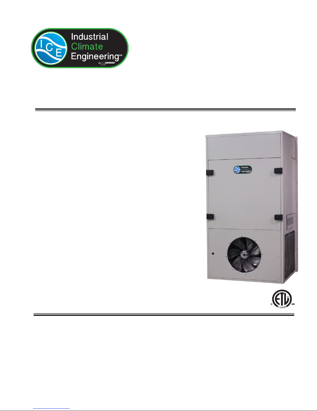
Vertical Air Conditioners
Models ECUA90/120/150/180/240
Chapter 1 Description ........................... 5
Chapter 2 Installation ......................... 12
Chapter 3 Start-Up ............................. 21
Chapter 4 Troubleshooting ................. 22
Chapter 5 Maintenance ....................... 25
Chapter 6 Warranty ............................ 26
Chapter 7 Start-Up Checklist .............. 27
Industrial Climate Engineering™ Division of AIRXCEL®, Inc.
P.O. Box 5104 • Cordele, Georgia 31010
2002 Hoover St. • Cordele, Georgia 31015
E-mail: icesales@airxcel.com • Internet: www.acice.com
The most current version of this manual can be found at www.acice.com.
Manufactured By:
(229) 273-9558 • Fax (229) 273-5154
Part Number 02118 04/2015 rev.3
Page 2
How To Use This Manual
This manual is intended to be a guide to Industrial Climate Engineering's line of vertical air conditioners. It contains
installation, troubleshooting, maintenance, warranty, and application information. The information contained in this
manual is to be used by the installer as a guide only. This manual does not supersede or circumvent any applicable
national or local codes.
If you are installing the air conditioner rst read Chapter 1 and scan the entire manual before beginning the installation as
described in Chapter 2. Chapter 1 contains general, descriptive information and provides an overview which can speed
up the installation process and simplify troubleshooting.
If a malfunction occurs, follow this troubleshooting sequence:
1. Make sure you understand how the air conditioner works (Chapters 1 & 3).
2. Identify and correct installation errors (Chapter 2).
3. Refer to the troubleshooting information in Chapter 4.
If you are still unable to correct the problem, contact the Factory at 1-229-273-9558 for additional assistance.
Please read the following “Important Safety Precautions” before beginning any work.
Important Safety Precautions
1. USE CARE when LIFTING or TRANSPORTING equipment.
2. TRANSPORT the UNIT UPRIGHT. Laying it down on its side may cause oil to leave the compressor and breakage
or damage to other components.
3. TURN ELECTRICAL POWER OFF AT THE breaker or fuse box BEFORE installing or working on the equipment.
LINE VOLTAGES ARE HAZARDOUS or LETHAL.
4. OBSERVE and COMPLY with ALL applicable PLUMBING, ELECTRICAL, and BUILDING CODES and ordi-
nances.
5. SERVICE may be performed ONLY by QUALIFIED and EXPERIENCED PERSONS.
* Wear safety goggles when servicing the refrigeration circuit
* Beware of hot surfaces on refrigerant circuit components
* Beware of sharp edges on sheet metal components
* Use care when recovering or adding refrigerant
6. Use COMMON SENSE - BE SAFETY-CONSCIOUS
This is the safety alert symbol . When you see this symbol on the air conditioning unit and in the instruction manu-
als be alert to the potential for personal injury. Understand the signal word DANGER, WARNING and CAUTION.
These words are used to identify levels of the seriousness of the hazard.
!
DANGER
!
WARNING
!
CAUTION
Failure to comply will result in death or severe personal injury and/or property damage.
Failure to comply could result in death or severe personal injury and/or property damage.
Failure to comply could result in minor personal injury and/or property damage.
IMPORTANT is used to point out helpful suggestions that will result in improved installation, reliability or operation.
SPECIFICATIONS SUBJECT TO CHANGE WITHOUT NOTICE.
© 04/2015 Industrial Climate Engineering™ Div. Airxcel™, Inc.
2
ECU 04/2015 rev.3
Page 3
WARNING
• If the information in these instructions are not followed exactly, a re may result
causing property damage, personal injury or loss of life.
• Read all instructions carefully prior to beginning the installation. Do not begin
installation if you do not understand any of the instructions.
• Improper installation, adjustment, alteration, service or maintenance can cause
property damage, personal injury or loss of life.
• Installation and service must be performed by a qualied installer or service agency in
accordance with these instructions and in compliance with all codes and requirements
of authorities having jurisdiction.
INSTALLER: Afx the instructions on the inside of the building adjacent to the
thermostat.
END USER: Retain these instructions for future reference.
Table of Contents
Chapter 1 Air Conditioner Description & Specications
1.1 General Description .................................................................................................................................5
1.2 Model Identication .................................................................................................................................5
1.3 Serial Number Date Code ........................................................................................................................5
1.4 Air Flow, Weights and Filter Sizes ...........................................................................................................6
1.5 General Operation ....................................................................................................................................6
1.6 Electronic Control Board Mode of Operation ..........................................................................................7
1.7 Optional Controls and Packages ..............................................................................................................8
1.8 Electrical Operation .................................................................................................................................9
Chapter 2 Installation
2.1 Equipment Inspection .............................................................................................................................12
2.2 Installation Requirements .......................................................................................................................12
2.3 Installation Materials ............................................................................................................................13
2.4 Porting and Duct Work ..........................................................................................................................15
2.5 Top Flange Installation ..........................................................................................................................15
2.6 Installing the Lifting Brackets ................................................................................................................16
2.7 Mounting the Unit .................................................................................................................................16
2.8 Electrical Connections ...........................................................................................................................17
Chapter 3 Start-Up
3.1 Check-Out of Cooling Cycle .................................................................................................................21
3.2 Check-Out of Heating Cycle ..................................................................................................................21
Chapter 4 Troubleshooting
4.1 Overview ................................................................................................................................................22
4.2 Failure Symptoms Guide ........................................................................................................................22
4.3 Compressor Troubleshooting .................................................................................................................23
4.4 Control Board Diagnosis ........................................................................................................................24
3
ECU 04/2015 rev.3
Page 4

Table of Contents
Chapter 5 Maintenance
5.1 Scheduled Maintenance .........................................................................................................................25
Chapter 6 Warranty
6.1 Limited Product Warranty ......................................................................................................................26
Chapter 7 Start-Up Check List
7.1 Start-Up Check List ................................................................................................................................27
Illustrations
Figure 1a. Typical Electrical Schematics for Units with One Compressor ............................................. 10
Figure 1b. Typical Electrical Schematics for Units with Two Compressors ........................................... 11
Figure 2. Top Flange and Lifting Bracket Installation .......................................................................... 16
Figure 3. Wall Mounting Detail ............................................................................................................. 17
Figure 4a. Thermostat Connection Diagram ........................................................................................... 20
Figure 4b. CommStat™ 3 Wiring Detail ................................................................................................. 20
Tables
Table 1 Cooling Performance and Air Flow ......................................................................................... 6
Table 2 Return Air Filter Sizes .............................................................................................................. 6
Table 3 Shipping Weights & Dimensions ............................................................................................. 6
Table 4 Minimum Clearances ............................................................................................................. 13
Table 5 Voltage Limitations ................................................................................................................ 13
4
ECU 04/2015 rev.3
Page 5
Chapter 1 Description & Specications
1.1 General Description
Industrial Climate Engineering's (ICE) Environmental Control Units (ECU) are a series of vertical
wall-mounted air conditioning systems that provide heating, cooling, and ventilation for electronic
equipment shelters, process control centers, E-Houses, and other applications with high internal heat
gains. The series includes multiple sizes and nominal cooling capacities from 90,000 to 240,000 BTUH.
Resistance heating elements are available in various wattages.
Industrial Climate Engineering ECU's feature an exclusive electronic control board.
The control board consolidates several of the electrical components, improves the air conditioner’s
reliability and has LED’s to indicate operating status and fault conditions to assist the service technician.
A complete description of functions of the control board is in Section 1.6
Other standard components include:
• Hot gas by-pass valve to allow operation in cold temperatures
• Thermal expansion valve to improve both efciency and capacity over a wide range of ambient
temperatures
• Phase monitor to prevent operation if the unit is not properly phased
The ECU's are designed for easy installation and service. Major components are accessible for service
beneath external panels.
All units have internal disconnects. Depending upon state and local code requirements, this feature
may eliminate the need for an external breaker or disconnect.
1.2 Model Identication
The model identication number is found on the data sticker. Rating plate located on side panel.
ECU D A ••• AC • ••• • • U A5 •••
D = Dual
Compressors
Environmental
Control Unit
1
The standard conguration is with one compressor. Add "D" to the model number to indicate dual compresssors.
2
The standard conguration is with the supply (conditioned) air at the top of the unit and the return air below it. In the reverse air ow conguration, the return
is at the top and the supply air below it.
3
Filter acces in the standard conguration is through the hinged, sheet metal panel on the exterior of the air conditioner. The "I" conguration allows access to
the lter from inside the building through the return air grille.
4
Three wire
5
Four wire
1
Refrigerant
A = R410A
Nominal Cooling
90 = 90,000 BTUH
120 = 120,000 BTUH
150 = 150,000 BTUH
180 = 180,000 BTUH
240 = 240,000 BTUH
System Type
Air Conditioner
Power Supply
D = 460V,3ø,60Hz
E = 380V,3ø,50Hz
C = 208/230V,3ø,60Hz
Z = 575V, 3ø,60Hz
Electric Heat – kW
000 = No Heat
090 = 9 kW
150 = 15 kW
180 = 18 kW
4
5
4
1.3 Serial Number Date Code
A = January E = May J = September D = 2014
B = February F = June K = October E = 2015
C = March G = July L = November F = 2016
D = April H = August M = December
Special Option Code
F = Reverse Air Flow
I = Factory Installed
Filter Rack Allows
Changing of Filters
from the Return Air
3
Grille
Ventilation
A = No Outside Air
(standard)
C = Economizer
2
Compressor
U = Scroll Compressor
Cabinet Color
116 = Beige
216 = Gray
(standard)
5
ECU 04/2015 rev.3
Page 6
1.4 Weights and Filter Sizes
Complete electrical and performance specications and dimensional drawings are in the Product Data
Sheet.
Model Number ECUA90 ECUA120 ECUA150 ECUA180 ECUA240
Cooling BTUH
Rated Air Flow (CFM2) 3,500 4,000 5,000 6,000 8,000
ESP3 @ Rated Conditions 0.25 0.30 0.35 0.35 0.40
1
Cooling rated at 95°F (35°C) outdoor and 80°F DB/67° WB (26.5°C DB/19.5°C WB) return air
2
CFM=Cubic Feet per Minute
3
ESP=External Static Pressure
Ratings are with no outside air. Performance will be affected by altitude.
Ratings are at 230 volts for 208/230 volt units (“C” models), 460 volts for “D” models, 380 volts for “E” models, 575 volts for “Z”
models. Derate performance by 17% for ACE (380v. 3ø, 50 Hz) models
Operation of units at a different voltage from that of the rating point will affect performance and air ow.
MODEL Description INCHES MILLIMETERS PART NO. FILTERS PER UNIT MERV RATING
ECUA90/120/150 Exterior Access Return Air Filter 25" x 16" x 2" 635 x 406 x 51 80137 3 8
ECUA90/120/150 Interior Access Return Air Filter 15" x 20" x 2" 381 x 508 x 51 92365 3 8
ECUA180/240 Exterior Access Return Air Filter 25" x 16" x 2" 635 x 406 x 51 80137 4 8
ECUA180/240 Interior Access Return Air Filter 24" x 18" x 2" 610 x 457 x 51 81257 4 8
1
94,000 125,000 150,000 170,000 235,000
Table 1. Cooling Performance and Air Flow Ratings
Table 2. Return Air Filter Sizes
MODEL
ECUA90
ECUA120
ECUA150
ECUA180
ECUA240
1.5 General Operation
Refrigerant Cycle (Cooling Mode)
The air conditioners use R-410A refrigerant in a conventional vapor-compression refrigeration cycle to
transfer heat from air in an enclosed space to the outside. A motorized impeller assembly blows indoor
air across the evaporator. Cold liquid refrigerant passing through the evaporator is boiled into gas by
heat removed from the air. The warmed refrigerant gas enters the compressor where its temperature
and pressure are increased. The hot refrigerant gas condenses to liquid as heat is transferred to outdoor
air drawn across the condenser by the condenser fan. Liquid refrigerant is metered with a thermal
expansion valve (TXV) into the evaporator to repeat the cycle.
Heating Mode
Unit Weight
LBS KG LBS KG Inches MM Inches MM Inches MM
1,053 478.6 1,178 535.5 98 2,489 56 1,422 42 1,067
1,160 527.3 1,285 584.1 98 2,489 56 1,422 48 1,219
1,166 530 1,291 586.8 98 2,489 56 1,422 48 1,219
2,307 1,046 2,420 1,098 98 2,489 76 1,930 51 1,295
2,523 1,144 2,636 1,196 98 2,489 76 1,930 51 1,295
Shipping
Weight
Height Width Depth
Shipping Dimensions
Table 3. Shipping Weights & Dimensions
A wall-mounted thermostat controls the heating cycle of models which incorporate resistance heating
elements. On a call for heat, the thermostat closes the heat relay to energize the indoor fan and the
resistance elements.
6
ECU 04/2015 rev.3
Page 7
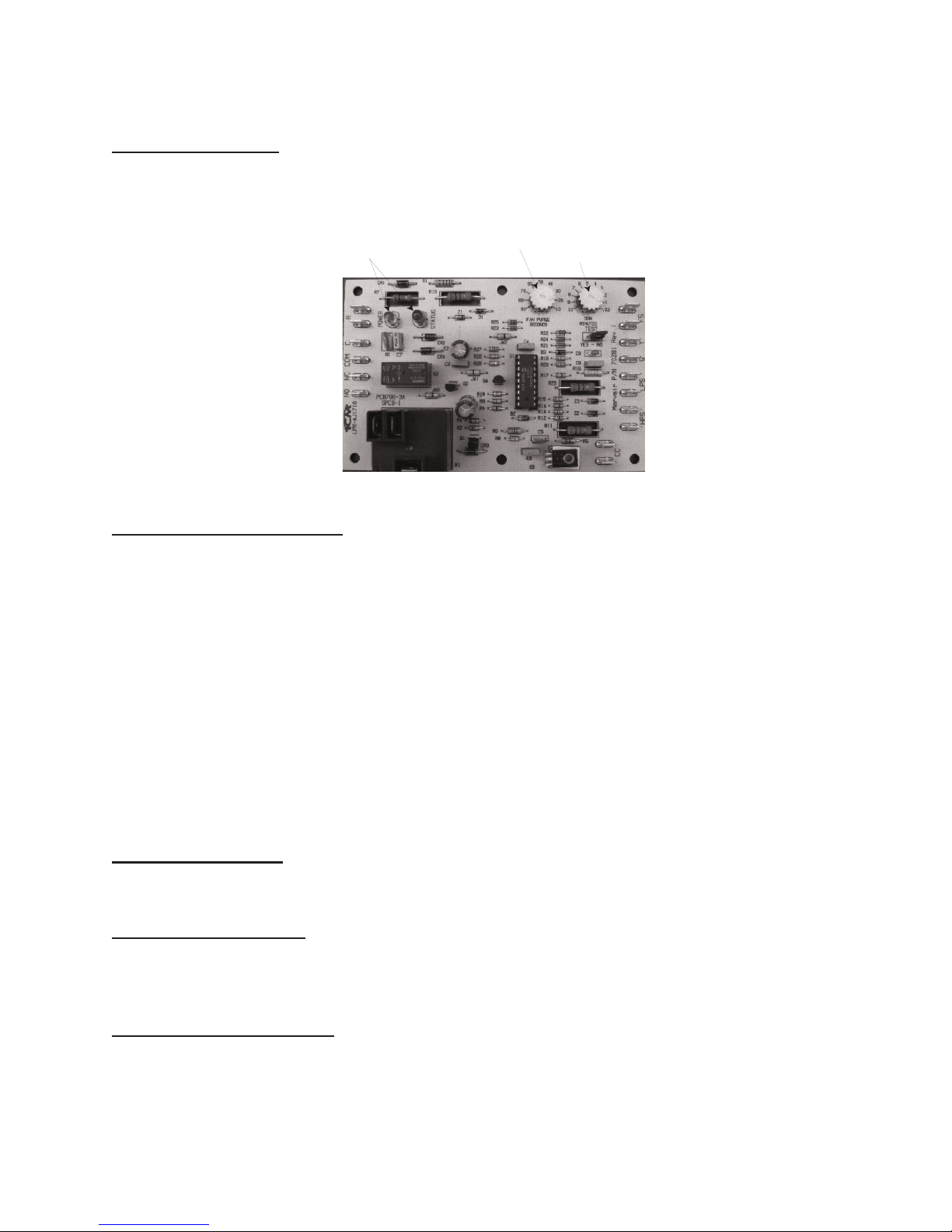
1.6 Electronic Control Board Mode of Operation
Normal
24 VAC power must be continuously applied to “R” and “C”. Upon a call for cooling “Y” and with
the high pressure switch (HPS) closed, the compressor will be energized. (Note: See the delay on
make feature.) The compressor will remain energized during the 3 minute timed low pressure by-pass
cycle. If the low pressure switch (LPS) is open after the 3 minute by-pass cycle, the compressor will
de-energize.
Lock-out
If either of the fault conditions (LPS or HPS) occurs twice during the same call for cooling, the control
board will enter into and indicate the lockout mode. In the lockout mode, the compressor is turned off.
If there is a call for indoor air ow “G”, the blower remains energized, the alarm output is energized and
the status LED will blink to indicate which fault has occurred. When the lockout condition is cleared, the
unit will reset if the demand for the thermostat is removed or when the power is reset. With the control
board, the user can now have either normally closed or normally open remote alarm dry contacts. The
air conditioners are factory wired to be normally open.
Delay on Break
If the compressor is de-energized due to a loss of a cooling “Y” call or the rst fault, the unit re-start
will be delayed 3 minutes from the time the contactor is de-energized. (Note: There is no delay on
break if the lockout condition is reset.)
Delay on Make
On initial power up only, the unit will wait 0.03 to 10 minutes from the cooling “Y” call before allowing the contactor to energize. The delay can be adjusted by the DOM wheel on the board. Factory
recommended wait is 3 minutes.
Low Pressure By-Pass Time
When starting, the low pressure switch (LPS) fault condition will be by-passed for 3 minutes before
the contactor is de-energized.
Post Purge
Upon a call for indoor airow “G” the blower will energize immediately. When in the cooling mode,
the blower will remain energized for 10 to 90 seconds (adjustable) after the compressor has been deenergized. The time period can be changed by fan purge wheel on the board. Factory setting is 90 seconds.
LED Indicator Lights
COLOR TYPE STATUS DESCRIPTION
Green Power Contstant On 24 VAC power has been applied
Red Status Contstant On Normal operation
Red Status 1 Blink High pressure switch has opened twice
Red Status 2 Blinks Low pressure switch has opened twice
High Pressure Switch
The high pressure switch is mounted on the liquid line. It is electrically connected to a lockout circuit
on the board which shuts down the system if the refrigerant pressure rises to 650 PSIG. This protects
the unit if airow through the condenser is blocked or if the outdoor fan motor fails.
Although the contacts of the high pressure switch close when the refrigerant pressure falls to approximately 450 PSIG, the system must be manually reset once the lockout circuit is activated. A manual
7
ECU 04/2015 rev.3
Page 8
reset is necessary to prevent harmful short-cycling. To reset switch, turn primary power off, then back
LEDs
POST PURGE
WHEEL
DELAY ON MAKE
(COMPRESSOR TIME DELAY)
WHEEL
on or turn thermostat system switch off, then back on.
Low Pressure Switch
The low pressure switch is mounted on the compressor suction line. It is designed to open if the refrigerant
pressure drops to 40 PSIG; it resets when the pressure rises to 60 PSIG. The switch protects the unit if
airow through the indoor blower is impeded, if the blower motor fails, or if there is a loss of refrigerant.
1.7 Optional Controls & Packages
Protective Coating Packages
Two corrosion protection packages are offered- one for the condenser section (the Coastal Environmental
package) and the other for the entire unit (the Coat-All Package).
The condenser protection package includes:
• Corrosion resistant fasteners
• Sealed or partially sealed condenser fan motor
• Two layer epoxy/urethane applied to all exposed internal copper and metal in the in the condenser
section
• An impregnated polyurethane on the condenser coil
The Coat-all package includes all of the above but also includes an impregnated polyurethane on the
evaporator coil and the two layer epoxy/urethane on all exterior and interior components and sheet metal.
(Note: the internal sheet metal which is insulated and the internal control box are not coated).
Dirty Filter Indicator
A diaphragm type of indicator measures the air pressure on either side of the lter and when the pressure
drops below the set point, a red LED is illuminated. The set point is adjustable.
Protective Coil Coatings
Either the condenser or evaporator coil can be coated. For harsh conditions, e.g., power plants, paper mills
or sites were the unit will be exposed to salt water, the condenser coil should be coated. Note: Cooling
capacity may be reduced by up to 5% on units with coated coils.
Cabinet Color and Material
The air conditioners are available in two standard cabinet colors -the standard grey with beige as an option.
The standard cabinet’s sides, top and front panels are constructed of 16 gauge painted steel. Contact your
ICE representative for color chips, custom colors and 316 stainless steel cabinets.
8
ECU 04/2015 rev.3
Page 9

Fresh Air Damper
Allows introduction of outside air into the building to provide positive pressurization. Field installed
on either the left or right hand side of the unit.
Dual Compressors With Lead/Lag Operation
Freeze Sensor On Indoor Coil
Prevents frost on the indoor coil caused by a loss of air ow or restrictive duct work. Field installed.
Filter Access From Return Air Grille
Factory or eld installed lter bracket allows changing and access to the lters from the return air grille.
See model ID, special option code “I”.
Reverse Air Flow Conguration
Location of Supply and Return Air Openings are reversed.
1.8 Electrical Operation
The compressor and condenser fan are energized with a contactor controlled by a 24 VAC pilot signal.
Some compressors incorporate an internal PTC crankcase heater that functions as long as primary power
is available. The heater drives liquid refrigerant from the crankcase and prevents loss of lubrication
caused by oil dilution. Power must be applied to the unit for 24 hours before starting the compressor.
The condenser (outside fan) motor is energized by the same contactor.
The indoor evaporator fan motor is controlled by the fan purge on the electronic control board.
9
ECU 04/2015 rev.3
Page 10

Figure 1a. Typical Electrical Schematic for Units with One Compressor
10
ECU 04/2015 rev.3
Page 11

NOTICE:
MODELS 180-240 HAVE TWO INDEPENDENT
ELECTRICAL CIRCUITS AND EACH ELECTRICAL
CIRCUIT IS WIRED THE SAME AS SHOWN.
Figure 1b. Typical Electrical Schematic for Units with Two Compressors
11
ECU 04/2015 rev.3
Page 12

Chapter 2 Installation
WARNING
Failure to observe and follow Warnings and Cautions and these Instructions could result
in death, bodily injury or property damage. Read this manual and follow its instructions
and adhere to all Cautions and Warnings in the manual and on the ICE unit.
2.1 Equipment Inspection
Concealed Damage
Inspect all cartons and packages upon receipt for damage in transit Remove cartons and check for
concealed damage. Important: keep the unit upright at all times. Remove access panels and examine
component parts. Inspect refrigerant circuit for fractures or breaks. The presence of refrigerant oil
usually indicates a rupture. If damage is apparent, immediately le a claim with the freight carrier.
Units that have been turned on their sides or tops may have concealed damage to compressor motor
mounts or to the oil system. If the unit is not upright, immediately le a claim for concealed damages
and follow these steps:
1. Set unit upright and allow to stand for 24 hours with primary power turned on.
2. Attempt to start the compressor after 24 hours.
3. If the compressor will not start, makes excessive noise, or will not pump, return the unit to the
freight carrier.
2.2 Installation Requirements
General
1. Inspect unit for completeness. Check for missing parts (e.g. hardware). Refer to the installation
kit information in section 2.3.
2. Remove access panels and check for loose wires. Tighten screw connections.
3. Complete and mail the warranty registration card.
You must consider all of the following when choosing the installation site:
1. Noise. Install the unit so that the least amount of noise will be transmitted to inhabited spaces.
2. Condensate Drainage. Condensate produced during operation must be discharged to a suitable
drain.
3. Placement.
A) Place the unit in a shaded area, if possible.
B) Install it above ground for protection against ooding.
C) The unit exhausts air. Be sure that the airow is not impeded by shrubbery or other obstruc-
tions.
D) When installing multiple units, please note the recommended clearances noted in Table 4.
4. Airow Requirements:
The maximum static pressure for the ECUA90 is 1.2 IWG (300 Pa) and 1.8 IWG (450 Pa) for the
ECUA120 and 150. Keep duct lengths as short as possible. Do not obstruct airow through the
unit.
Duct work should be designed and installed in accordance with all applicable safety codes and
standards. Industrial Climate Engineering strongly recommends referring to the current edition of
12
ECU 04/2015 rev.3
Page 13

the National Fire Protection Association Standards 90A and 90B before designing and installing duct
work. The duct system must be engineered to insure sufcient air ow through the unit to prevent
over-heating of the heater element. This includes proper supply duct sizing, sufcient quantity of
supply registers, and adequate return and lter areas. Duct work must be of correct material and must
be properly insulated. Duct work must be constructed of galvanized steel with a minimum thickness
of .019 inches. Duct work must be rmly attached, secured, and sealed to prevent air leakage. See
section 2.4 for additional duct work requirements.
5. Clearances:
Note the minimum clearances required for proper operation and service.
MODEL
ECUA90/120/150/180/240 24 inches (76 cm) 18 inches (46 cm) 24 inches (61 cm)
MIN. CLEARANCE AROUND
SIDES (SINGLE UNIT)
MIN. CLEARANCE BETWEEN
UNITS (TWO UNITS)
MIN. SPACE
ABOVE UNIT
Table 4. Minimum Clearances
6. Codes:
Make sure your installation conforms to all applicable electrical, plumbing, building, and municipal
codes. Some codes may limit installation to single story structures.
7. Electrical Supply:
The power supply must have the appropriate voltage, phase, and ampacity for the model selected.
Voltage must be maintained above minimum specied values listed below. Refer to the data sticker
on the unit for ampacity requirements.
Electrical Rating Designations* A C D Z
Nominal Voltage 208/230 208/230 460 575
Phase 1 3 3 3
Minimum Voltage 197 197 414 518
Maximum Voltage 253 253 506 600
* Letters refer to model number code designations. Refer to page 5.
Table 5. Voltage Limitations
2.3 Installation Materials
The ECU is shipped with a top bracket and lifting brackets. The top bracket provides a method of sealing
the top of the unit from water intrusion. The bracket is shipped attached to the top of the unit. Before
installing the ECU, remove the bracket and reattach as described in Section 2.5
The Lifting brackets are shipped attached to the back panel of the ECU. These brackets provide a method
for lifting the ECU. The installation of the brackets is described in Section 2.6.
13
ECU 04/2015 rev.3
Page 14

Kit Components:
Accessories:
The package may include other factory-supplied items (optional):
P/N Description
S/04581 CommStat 3 Controller, Solid State Lead/Lag Controller
S/07846 CommStat 4 Controllers, Solid State Lead/Lag Controller
50123 Digital thermostat. 1 stage heat, 1 stage cool. 7 day programmable. Fan switch: Auto &
On. Auto-change over. Keypad lockout. Non-volatile program memory.
92508 Double deection Aluminum supply grille for ECU90/120/150. 42½" x 15½"
(1,080 mm x 394 mm)
92507 Aluminum Return Grille for ECU90/120/150. 42½" x 21½" (1,080 mm x 546 mm)
Additional Items Needed:
Additional hardware and miscellaneous supplies (not furnished by ICE®) are needed for installation.
The list below contains approximate quantities of items typically needed for mounting a unit on a
wood frame wall structure. Concrete or berglass structures have different requirements. ICE cannot
recommend a specic method of attaching the air conditioner to the building due to the wide variety
of building types, code requirements, wall construction and specic installation conditions. The installation of the air conditioner to the building must take in to account all of these factors and follow best
industry practices to provide a safe and secure attachment to the building.
• (14) mounting bolts for unit mounting anges. The length needed is typically the wall thickness
plus one inch (25 mm).
• (28) washers
• (14) hex nuts
• Silicone Sealer to seal around cracks and openings
• Minimum 5 conductor low voltage multicolored wire cable (i.e. thermostat wire)
• Appropriate electrical supplies such as conduit, electrical boxes, ttings, wire connectors, etc.
• High voltage wire, sized to handle the MCA (minimum circuit ampacity) listed on the data plate.
• Over-Current Protection Device sized in accordance with the MFS (maximum fuse size) listed on
the unit data plate.
WARNING
FIRE HAZARD
Improper adjustment, alteration, service, maintenance or installation could cause serious
injury, death and/or property damage.
Installation or repairs made by unqualied persons could result in hazards to you and
others. Installation MUST conform with local codes or, in the absence of local codes, with
codes of all governmental authorities have jurisdiction.
The information contained in this manual is intended for use by a qualied service
agency that is experienced in such work, is familiar with all precautions and safety
procedures required in such work, and is equipped with the proper tools and test
instruments.
14
ECU 04/2015 rev.3
Page 15

2.4 Porting and Duct Work
General Information
Note: The following instructions are for general guidance only. Due to the wide variety of installation possibilities, specic instructions will not be given. When in doubt, follow standard and accepted
installation practices, or contact ICE™ for additional assistance.
Wall Openings
Measure the dimensions of the supply and return ports on the unit.
Cut the openings in the exterior wall for the supply and return. IMPORTANT: All units with electric
heat must have 1" (25.4mm) clearance on all four sides of the supply outlet duct ange on the
unit. The 1" (25.4mm) clearance must extend on all sides of the supply duct for the rst 3 feet
(1 meter) from the unit.
IMPORTANT: ICE™ requires a minimum of 1" (25.4mm) from the surface of any supply ducts to
combustible material for the rst 3 feet (1 meter) of the duct.
Ducting
Extensions should be cut ush with the inside wall for applications without duct work.
Applications using duct work should be designed and installed in accordance with all applicable safety
codes and standards. ICE strongly recommends referring to the current edition of the National Fire
Protection Association Standards 90A and 90B before designing and installing duct work. The duct
system must be engineered to insure sufcient air ow through the unit to prevent over-heating of the
heater element. This includes proper supply duct sizing, sufcient quantity of supply registers, adequate
return and lter area. Ductwork must be of correct material and must be properly insulated. Duct work
must be constructed of galvanized steel with a minimum thickness of .019 inches for the rst 3 feet (1
meter). Ductwork must be rmly attached, secured and sealed to prevent air leakage. Do not use duct
liner on inside of supply duct within 4 feet (122cm) of the unit.
Galvanized metal duct extensions should be used to simplify connections to duct work and grilles. Use
fabric boots to prevent the transmission of vibration through the duct system. The fabric must be U.L.
rated to a minimum of 197°F (92°C).
Minimum Airow Requirements
The duct system must be engineered to assure sufcient air ow through the unit even under adverse
conditions such as dirty lters, etc.
2.5 Top Flange Installation (See Figure 2)
1. All models have built-in side mounting anges.
2. Attach the top ange to the top of the air conditioner. The holes in the top of the air condtioner have
been predrilled. Remove the 4 screws in these holes and use these screws to attach the top ange
to the air conditioner.
3. Apply a bead of silicone sealer on the wall side of the bottom support brackets on the unit. Circle
the mounting holes with the silicone bead.
15
ECU 04/2015 rev.3
Page 16

Figure 2. Top Flange and Lifting Bracket Installation
2.6 Installing the Lifting Brackets
The ECU90/120/150 have lifting brackets that can be installed on the top of the side panels. These
brackets allow the unit to be picked up thru lifting eyes in the brackets.The lifting brackets are shipped
attached to the back panel of the ECU. Attach the brackets to the left and right side panels as shown in
Figure 2. The 4 screws for attaching the brackets are shipped in the holes at the top of the side panels.
When attaching the brackets, make sure the top of the bracket is angled towards the center of the ECU.
2.7 Mounting The Unit
1. For wiring into the back of unit, locate the lower of the two knockouts on the wall side of the unit.
Drill a one inch hole in the shelter wall to match this opening. Allow sufcient clearance to run
3/4" conduit through the hole and to the unit.
2. Lift the unit into position using an appropriate and safe lifting device.
3. Make sure that the duct anges are properly aligned with the wall opening. Adjust as necessary.
4. Note the holes in each side ange. Using the holes for guides, drill holes through the wall with a
drill bit. Insert the bolts through the anges. Install nuts and washers on the inside of the shelter.
Tighten the bolts to secure the unit.
5. Apply a bead of silicone where the side and top anges contact the exterior wall.
6. On the inside of the shelter, install the wall sleeves in the supply and return air openings. The sleeves
may be trimmed to t ush with the inside wall.
7. Check the t of each sleeve to its mating ange for possible air leaks. Apply silicone sealer to close
any gaps. Install the air return and supply grilles.
16
ECU 04/2015 rev.3
Page 17

For units with electric heat, a one inch clearance is required around the duct extensions. The duct extensions must be constructed of
galvanized steel with a minimum thickness of .019” as per the NFPA standards 90A & 90B.
Figure 3. Air Conditioner Wall Mount Detail
2.8 Electrical Connections
WARNING
ELECTRICAL SHOCK HAZARD
Failure to follow safety warnings exactly could result in serious injury, death, and/or
property damage.
Turn off electrical power at fuse box or service panel BEFORE making any electrical
connections and ensure a proper ground connection is made before connecting line
voltage.
Important
All electrical work must meet the requirements of local codes and ordinances. Work should be
done only by qualied persons.
The units may incorporate an internal crankcase heater for compressor protection. The crankcase
heater must be energized for at least 24 hours prior to starting the compressor.
Scroll compressors, like several other types of compressors, will only compress in one rotational direction.
The direction of rotation is not an issue with single-phase compressors since they will always start and
run in the proper direction. However, three phase compressors will rotate in either direction depending
upon phasing of power. Since there is a 50-50 chance of connecting power in such a way as to cause
rotation in the reverse direction, it is imperative to conrm that the compressor is rotating in the proper
direction at the initial eld start-up of the system. Verication of proper rotation is made by observing
17
ECU 04/2015 rev.3
Page 18

that the suction pressure drops and the discharge pressure rises when the compressor is energized. An
alternate method of verication for self contained system with small critical refrigerant charges, where
the installation of gauges may be objectionable, can be made by monitoring the temperature of the
refrigerant lines at the compressor. The temperature should rise on the discharge line while the suction
line temperature decreases. Reverse rotation also results in a substantially reduced current draw when
compared to tabulated values.
There is no negative impact on durability caused by operating three phase compressors in the reversed
direction for a short duration of time, usually dened as less than one hour. However, after several
minutes of operation the compressor's internal protector will trip. The compressor will then cycle on
the protector until the phasing is corrected. Reverse operation for longer than one hour may have a
negative impact on the bearings.
To change the rotation, turn off power to the unit and reverse L1 & L2 at the disconnect in the air
conditioner.
The middle front panel provides access to the electrical/control box and to the lters. This panel has hinges
on the left and right hand side. This panel should ONLY be opened by using the two hinges on the left
side OR the two hinges on the right side. NEVER OPEN ALL FOUR HINGES SIMULTANEOUSLY.
If all four hinges are opened simultaneously, the front panel will drop and may cause serious injury
and damage the panel.
DANGER
NEVER open all four hinges simultaneously. The panel should ONLY be opened by using
the two hinges on the left side OR the two hinges on the right side.
High Voltage Wiring
The power supply should have the proper voltage, phase, and ampacity for the selected model.
1. Refer to the electrical data on the data sticker on the unit for eld wiring requirements of the unit.
Size the incoming power supply lines and the fuse(s) or HACR breaker(s) according to requirements
described in the National Electric Code. Run the power conductors through the knockouts on the
side or back of the unit. Use appropriate conduit and strain reliefs.
CAUTION
Note: Power supply service must be within allowable range (+10% - 5%) of rated voltage
stamped on the unit rating plate. To operate nominal 230/208V unit at 208V, change the
transformer line tap from 240V to 208V following the instruction on wiring label in unit.
2. Connect the wires to the input side of the internal breaker or terminal block L1, L2, & L3 for three-
phase models.
3. Install the ground wire on the ground lug.
4. For units designed for operation on 208/230V, 60Hz power supply, the transformer is factory wired
for a 230V power supply. For a 208V power supply, remove the orange lead from the transformer
and connect the red lead. Insulate the orange lead.
CAUTION
The external breaker(s) that provide power to the air conditioner must be sized per the
maximum Fuse Size (MFS) shown on the Unit's data label.
18
ECU 04/2015 rev.3
Page 19

Dual Unit Phasing
For applications where one controller operates two units, e.g., the CommStat 4.
1. Wire each unit as described in steps 1 through 4 above.
2. Test for proper phasing as follows:
A. Power up the units.
B. Using an AC volt meter set to the 300 volt scale, measure voltage between terminal L1 on the
compressor contactor of unit #1 and terminal L1 on the compressor contactor of unit #2 If
voltage is present, units are wired out of phase and must be rewired.
C. If units are not in phase, turn off power and reverse the eld power leads connected to the
internal circuit breaker on one of the units only.
D. Restore power and retest the phase (step B). When the voltage reads "0", the units are in phase.
E. Turn off power and proceed.
Low Voltage Wiring
IMPORTANT. The following instructions are generic wiring instructions and may not be applicable
for air conditioners with various options. Always refer to the wiring diagram in the air conditioner for
the proper method to wire your unit.
1. On single units, pull the low voltage wiring (e.g., 18 gauge 4-conductor Class 2 thermostat wire)
from the air conditioners into the thermostat / subbase assembly. See Figure 4a for connections to
various thermostats.
2. Mount the thermostat on the wall of the shelter. The thermostat should be located so that the supply
air from the unit does NOT blow directly on to the thermostat. Connect the thermostat to the terminal
block in the air conditioner as shown in Figure 6a.
3. On dual units, refer to either the ICE CommStat 3 or CommStat 4 Controller Specication sheet.
Wire the two air conditioners to the Lead/Lag Controller, according to the wiring diagram on the
specication sheet.
Remote Signalling:
Terminals 5 & 7(N.O.) and 6 & 7 (N.C.) on the air conditioners terminal board are dry
contacts which can be used for remote signalling in the event of a/c cutoff on low or high pressure limit.
Continuous fan operation: For continuous indoor fan operation on single units, install a jumper between
terminals 8 and 3.
CommStat 3 Controller (See Figure 4b)
The CommStat 3 Controller by ICE is a solid state control package designed to operate a fully
or partially redundant air conditioning system for a telecommunication cabinet or shelter. The
CommStat 3 Controller is factory programmed with standard industry set points to facilitate installation.
If desired, each of the set points can be quickly and easily changed in the eld by the installer. See
CommStat 3 Product Data Sheet for installation and programming instructions.
CommStat 4 Lead /Lag Controller
Please refer to the Product Data sheet for the CommStat 4 controller for complete instructions
on installing and programming this controller.
19
ECU 04/2015 rev.3
Page 20

Figure 4a. Thermostat Connection Diagram
Figure 4b. CommStat 3 Wiring Diagram
20
ECU 04/2015 rev.3
Page 21

3.1 Check-Out of Cooling Cycle
Important: Be sure that the crankcase heater (if used) has been energized for at least 24 hours
before starting the unit(s). Double-check all electrical connections before applying power. All air
conditioners with scroll compressors running on 3Ø power must be checked for proper rotation
during the initial start-up. Please refer to Section 2.8 for determining if the 3Ø compressors are
rotating correctly. Incorrect rotation can damage the compressor and is not covered by the warranty
Procedure:
1. Set the cooling set point temperature on the wall thermostat to a point higher than the ambient tem-
perature. Set the heating set point temperature to a temperature that is lower than the ambient.
2. Set the thermostat system switch in the AUTO position. Nothing should operate at this time.
3. Set the time delay in the control box to three minutes. See Section 1.6.
4. Slowly lower the thermostat's cooling set point temperature until the switch closes. The indoor fan
should operate.
Once the indoor fan turns on, allow approximately three minutes for the compressor to start.
5. To stop cooling, slowly raise the thermostat cooling set point to a temperature higher than the
ambient.
Chapter 3 Start-Up
If the unit fails to operate, refer to the troubleshooting information in Chapter 4.
Follow the same procedure for additional units.
NOTE: The fan purge allows the indoor fan to run for approximately 90 seconds after the compressor
is off. This operation provides a small improvement in system rated efciency.
3.2 Check-Out of Heating Cycle
Procedure: (Applies only to units with resistance elements)
1. Raise the heating set point temperature to a setting which is higher than the ambient temperature.
The fan and electric heat should immediately cycle on.
2. Move the system switch to the "OFF" position. All functions should stop.
21
ECU 04/2015 rev.3
Page 22

4.1 Overview
The middle front panel provides access to the electrical/control box and to the lters. This panel has hinges
on the left and right hand side. This panel should ONLY be opened by using the two hinges on the left
side OR the two hinges on the right side. NEVER OPEN ALL FOUR HINGES SIMULTANEOUSLY.
If all four hinges are opened simultaneously, the front panel will drop and may cause serious injury
and damage the panel.
NEVER open all four hinges simultaneously. The panel should ONLY be opened by using
the two hinges on the left side OR the two hinges on the right side.
A comprehensive understanding of the operation of the air conditioner is a prerequisite to troubleshooting. Please read the Chapter 1 for basic information about the unit.
Our air conditioners are thoroughly tested before they are shipped from the factory. Of course, it is
possible that a defect may escape undetected, or damage may have occurred during transportation.
However, the great majority of problems result from installation errors.
If you experience difculties with the unit, please review the installation steps in Chapter 2.
Much time can be saved by taking a thoughtful and orderly approach to troubleshooting. Start with a
visual check - are there loose wires, crimped tubing, missing parts, etc? Begin deeper analysis only
after making this initial inspection.
Chapter 4 Troubleshooting
DANGER
The troubleshooting information in this manual is basic. The troubleshooting section contains problem/
solution charts for general problems, followed by a compressor section.
Not every problem can be anticipated. If you discover a problem that is not covered in this manual, we
would be very grateful if you would bring it to the attention of our service department for incorporation
in future revisions.
As always, please exercise caution and good judgement when servicing the air conditioner. Use only
safe and proven service techniques. Use refrigeration goggles when servicing the refrigeration circuit.
The refrigerant circuit has hot surfaces, and the electrical voltages inside of
the unit may be hazardous or lethal. SERVICE MAY BE PERFORMED ONLY BY
QUALIFIED AND EXPERIENCED PERSONS.
4.2 Failure Symptoms Guide
PROBLEM/SYMPTOM LIKELY CAUSE(S) CORRECTION
A. Unit does not run.
NOTE: An internal anti-short-cycle
timer will prevent the unit
from starting for .2 to 8
minutes following start-up.
1. Power supply problem.
2. Tripped internal disconnect.
3. Shut off by external thermostat or
thermostat is defective.
WARNING
1. Check power supply for adequate phase and voltage.
Check wiring to unit and external breakers or fuses.
2. Check internal circuit protection devices for continuity.
3. Check operation of wall-mounted thermostat.
4. Unit off on high or low pressure limit.
5. Internal component or connection
failure.
22
4. Reset pressure switch.
5. Check for loose wiring. Check components for failure.
ECU 04/2015 rev.3
Page 23

PROBLEM/SYMPTOM LIKELY CAUSE(S) CORRECTION
B. Unit runs for long periods or continu-
ously; cooling is insufcient.
C. Unit cycles on high/low pressure
limit.
D. Unit blows fuses or trips circuit
breaker.
1. Dirty lter or reduced airow
2. Low refrigerant.
3. Component failure.
4. Unit undersized for job.
1. Loss or restriction of airow.
2. Restriction in refrigerant circuit.
3. Refrigerant overcharge (following
eld service)
4. Defective pressure control.
1. Inadequate circuit ampacity.
1. Check air lter(s). Check blower operation. Remove
airow restriction.
2. Check for proper charge and possible refrigerant leak.
3. Check internal components, especially compressor for
proper operation.
4. Add additional units for greater capacity.
1. Check blower assembly for proper operation. Look
for airow restrictions, e.g.. the air lter. Check blower
motor and condenser fan.
2. Check for blockage or restriction, especially lter drier
and capillary tube assembly.
3. Evacuate and recharge to factory specications.
4. Check limit cutout pressures. Control is set to actuate at
approximately 60 PSIG (low pressure) and 650 PSIG (high
pressure).
1.
Note electrical requirements in Chapter 2 and correct
as necessary.
2. Short, loose, or improper connection
in eld wiring.
3. Internal short circuit. Loose or
improper connection(s) in unit.
4. Excessively high or low supply volt-
age or phase loss (3ø only).
E. Water on oor near unit. 1. Obstruction in condensate line.
2. Obstruction or leak in condensate
pan.
3. Unit is not level.
F. No space heating or reduced heating
(units equipped with resistance elements)
1. Defective heating element(s).
2. Thermal limit open.
3. Defective heater contactor.
2. Check eld wiring for errors.
3. Check wiring in unit. See wiring and schematic dia-
grams. Test components (especially the compressor)
for shorts.
4. Note voltage range limitations specic to the compressor troubleshooting section.
1. Check for clog or restriction.
2. Check pan for leak or blockage.
3. Level unit.
1. Check resistance element(s) for continuity.
2. Check continuity across thermal limit switch.
3. Check relay for proper operation. Replace if defective.
23
ECU 04/2015 rev.3
Page 24

4.3 Compressor
Troubleshooting
NOTE: It is important to rule out other component failures before condemning the compressor.
The following electrical tests will aid diagnosis:
1. Start-Up Voltage: Measure the voltage at the compressor contactor during start-up. The voltage
must exceed the minimum shown in Table 5, section 2.2, or compressor failure is likely. A low
voltage condition must be corrected.
2. Running Amperage: Connect a clip-on type ammeter to the (common) lead to the compressor.
Turn on the supply voltage and energize the unit. The compressor will initially draw high amperage;
it should soon drop to the RLA value or less. If the amperage stays high, check the motor winding
resistances.
NOTE: Feel the top of the compressor to see if it has overheated. If it is hot, the internal overload
may be open. You may have to wait several hours for it to reset.
3. Motor Winding Resistances: Using a digital volt-ohm meter (VOM), measure the resistance
across the compressor windings as shown below.
SINGLE
PHASE
R
2
S
Resistance can be measured as shown above. Any deviation from above values could indicate a
defective compressor.
4. High Voltage/Insulation Test: Test internal leakage with a megoh meter. Attach one lead to the
compressor case on a bare metal tube and to each compressor terminal to test the motor windings.
A short circuit at high voltages indicates a motor defect. Do not do this test under vacuum.
5. On single phase models, check the capacitor by substitution.
4.4 Control Board Diagnosis
The control board (see section 1.6 for a complete description of the control board) has a red diagnostic
LED which indicates the lockout fault. The control board will enter into and indicate lockout if either
of the fault conditions (LPS or HPS) occur twice.
The contactor must be closed before the rst fault condition can be recognized by the control board.
The contactor will be closed 3 minutes after the unit is energized and only if cooling is required. The
rst fault condition will open the contactor and shutdown the unit. The contactor on the unit that has
the fault condition must be closed before the second fault condition can be recognized by the control
board. The contactor on the unit with the fault condition will close after 3 minutes if the unit is still
calling for cooling and if the fault condition no longer exists. If you get a second fault condition, the
contactor will open and shutdown the unit. The “red” led will have one blink if the high pressure switch
has opened twice and will have two blinks if the low pressure switch has opened twice. The unit must
be in the cooling mode (compressor contactor Closed) before a fault condition can occur.
C
R3 > R2 > R
R
1
R3 = R2 + R
R
R
3
1
1
THREE
PHASE
T
1
3
R3 = R2 = R
R
1
T
3
R
2
T
R
2
1
24
ECU 04/2015 rev.3
Page 25

The middle front panel provides access to the electrical/control box and to the lters. This panel has hinges
on the left and right hand side. This panel should ONLY be opened by using the two hinges on the left
side OR the two hinges on the right side. NEVER OPEN ALL FOUR HINGES SIMULTANEOUSLY.
If all four hinges are opened simultaneously, the front panel will drop and may cause serious injury
and damage the panel.
NEVER open all four hinges simultaneously. The panel should ONLY be opened by using
the two hinges on the left side OR the two hinges on the right side.
5.1 Scheduled Maintenance
Industrial Climate Engineering strongly recommends that the air conditioner be serviced a minimum
of twice a year – once prior to the heating season and once prior to the cooling season. At this time
the lters, evaporator coil, condenser coil, the cabinet, and condensate drains should be serviced as
described below. Also at this time, the air conditioner should be operated in the cooling and heating
cycles as described in Chapter 3, Start-Up. In addition to this seasonal check-out, the air conditioner
should be maintained as follows:
Air Filter
Replace the air lter whenever it is visibly dirty. Never operate the unit without the lter in place. Depending upon the conguration of your unit, access to the lter can be either from the outside through
the hinged door or from the return grille on the inside of the building.
Chapter 5 Maintenance
DANGER
Evaporator
If the evaporator becomes clogged or dirty, it may be cleaned by careful vacuuming or with a commercial evaporator cleaning spray. DO NOT use a solvent containing bleach, acetone, or ammable
substances. Turn off power before cleaning. Be careful not to wet any of the electrical components.
Be sure the unit has dried before restarting.
Condenser
Periodically inspect the outdoor condenser coil and the cabinet air reliefs for dirt or obstructions.
Remove foreign objects such as leaves, paper, etc.
If the condenser coil is dirty, it may be washed off with a commercial solvent intended for this purpose.
TURN OFF POWER BEFORE CLEANING! Be sure that all electrical components are thoroughly
dry before restoring power. Use a n comb of the correct spacing to straighten mashed or bent ns.
Cabinet
The cabinet may be cleaned with a sponge and warm, soapy water or a mild detergent. Do not use
bleach, abrasive chemicals or harmful solvents.
Drains
The condensate is drained from the condensate pan through two drains – one on the left side of the
pan and the other on the right side. The condensate lines drain to the outside at the bottom of the unit
through the base pan. Each of the drain lines is looped to form a trap.
Regularly check each drain line to make sure it is not obstructed. If a commercial drain solvent is used,
ush out the drain pan and system with sufcient water to remove the solvent. Some solvents can cause
the drain pan to corrode.
Lubrication
Oiling of the condenser fan motor or the evaporator blower motor is not recommended.
25
ECU 04/2015 rev.3
Page 26

6.1 Limited Product Warranty
If any part of your Industrial Climate Engineering™ Environmental Control Unit (ECU) fails because
of a manufacturing defect within eighteen months from the date of original shipment by ICE or within
twelve months from the date of original start-up, whichever is the earlier date, ICE will furnish without
charge, EXW Cordele, Georgia, the required replacement part. Any transportation, related service labor,
diagnosis calls, lter, driers and refrigerant are not included. The owner must provide proof of the
date of the original start-up. The owner’s registration card led with ICE, the contractor’s invoice, the
certicate of occupancy or similar document are examples of proof of the date of the original start-up.
The responsibility of the Owner of the Equipment includes the following:
1. To operate the equipment according to the manufacturer’s instructions.
2. To provide easy accessibility for service.
3. To check and reset any circuit breaker(s) and/or disconnect(s) before calling for service.
4. To keep the unit clean and free of dirt.
5. To replace any lters as required.
6. To keep the outdoor coil section clean and free of leaves, paper, etc.
7. To pay the charges incurred when any of the above have not been done.
8. To pay for repair or replacement of any material or part other than those within the ICE unit
or thermostat itself.
Chapter 6 Warranty
The owner of the product may ship the allegedly defective or malfunctioning product or part to ICE, at
such owner’s expense, and ICE will diagnose the defect and, if the defect is covered under this warranty,
ICE will honor its warranty and furnish the required replacement part. All costs for shipment and risk of
loss during shipment of the product or part to ICE and back to the owner shall be the responsibility and
liability of the owner. Upon written request by an owner, ICE may arrange for remote diagnosis of the
allegedly defective or malfunctioning product or part but all costs for transportation, lodging and related
expenses with regard to such diagnostic services shall be the responsibility and liability of the owner.
An owner requesting performance under this Warranty shall provide reasonable access to the allegedly
defective or malfunctioning product to ICE and its authorized agents and employees.
This warranty only applies to products purchased and retained for use within the U.S.A, Canada and
Mexico. This warranty does not cover damage caused by improper installation, misuse of equipment
or negligent servicing.
THIS WARRANTY AND SERVICE POLICY CONSTITUTE THE EXCLUSIVE REMEDY OF ANY
PURCHASER OF A ICE ECU AND IS IN LIEU OF ALL OTHER WARRANTIES, EXPRESSED OR
IMPLIED, INCLUDING, WITHOUT LIMITATION, ANY IMPLIED WARRANTY OF MERCHANTABILITY OR FITNESS FOR USE, TO THE FULLEST EXTENT PERMITTED BY LAW. IN NO
EVENT SHALL ANY IMPLIED WARRANTY OF MERCHANTABILITY OR FITNESS FOR USE
EXCEED THE TERMS OF THE APPLICABLE WARRANTY STATED ABOVE AND ICE SHALL
HAVE NO OTHER OBLIGATION OR LIABILITY. IN NO EVENT SHALL ICE BE LIABLE FOR
INCIDENTAL OR CONSEQUENTIAL DAMAGES OR MONETARY DAMAGES.
THIS WARRANTY GIVES YOU SPECIFIC LEGAL RIGHTS, AND YOU MAY ALSO HAVE
OTHER RIGHTS WHICH
VARY FROM STATE-TO-STATE. Some states do not allow limitations or exclusions, so the above
limitations and exclusions may not apply to you.
26
NEW
ECU 04/2015 rev.3
Page 27

Chapter 7 Start-Up Check List
The middle front panel provides access to the electrical/control box and to the lters. This panel has hinges
on the left and right hand side. This panel should ONLY be opened by using the two hinges on the left
side OR the two hinges on the right side. NEVER OPEN ALL FOUR HINGES SIMULTANEOUSLY.
If all four hinges are opened simultaneously, the front panel will drop and may cause serious injury
and damage the panel.
NEVER open all four hinges simultaneously. The panel should ONLY be opened by using
the two hinges on the left side OR the two hinges on the right side.
7.1 Start-Up & Commissioning Form
Please complete the information on this form and return to Marvair by mail or fax. The mailing address
and fax number can be found at the end of the form.
A. Equipment Information
Date: ________________Equipment Owner _______________________________________
Installing Company: _____________________________Installer: ____________________
Address: _______________________________________ State _______________________
City: __________________________________________
DANGER
ICE Air conditioner: Model No. _____________________________________________
Serial No. _____________________________________________
Compressor: Model No. _____________________________________________
Serial No. _____________________________________________
Compressor: Model No. _____________________________________________
Serial No. _____________________________________________
B. Pre-Start Up
Is there any shipping damage? ❒Yes ❒No
If so, where? ________________________________________________________________
Will this damage prevent starting the unit? ❒Yes ❒No
Check Power Supply, does it agree with data sticker on air conditioner? ❒Yes ❒No
Has the ground wire been connected? ❒Yes ❒No
Has the circuit protection been sized and installed properly? ❒Yes ❒No
Controls
Are the thermostat control wiring connections made and checked? ❒Yes ❒No
Are all wiring terminals (including main power supply) tight? ❒Yes ❒No
If unit has a crankcase heater, has it been energized for 24 hours? ❒Yes ❒No
On a 208/230 v. units is control transformer (24 AC) wired for correct voltage? ❒Yes ❒No
27
ECU 04/2015 rev.3
Page 28

Condensate Section
Has water been placed in drain pan to conrm proper drainage? ❒Yes ❒No
Are correct lters in place? ❒Yes ❒No
Refrigerant Piping
If leaks are found, report any leaks to ICE Warranty Service Dept.
C. Check Rated Voltage at Terminal Block for Imbalance before starting of Unit.
❒208/230V 1 Phase ❒208/230V 3 Phase ❒460V 3 Phase
❒380V 3 Phase 50Hz. ❒575 3 Phase 60 Hz.
Measured Line to Line Volts L1&L2_______V. L1&L3 ________V. L2&L3______V.
(L1&L2 + L1&L3 + L2&L3)/3 = Avg. Voltage = _______________
Max. Deviation from avg. voltage = ______________volts
Voltage imbalance = (100 x Max. Deviation)/avg. Voltage = ___________%
A voltage deviation greater than 2% with the unit running should be addressed and corrected. Excess
voltage deviation can cause the compressor to overheat and to operate inefciently.
Example: Maximum Deviation from Average Voltage X 100 (for Percent)
Average voltage
Measured Voltages:
L1 & L2 = 241 Volts
L1 & L3 = 243 Volts = 717 / 3 = 239 Average Voltage
L2 & L3 = 233 Volts
239 - 233 = 6
239 X 100=2.5% Voltage Unbalance
Three phase units only check fan & compressor rotation.
28
ECU 04/2015 rev.3
Page 29

D. Heating Mode Check & Record Readings
Room Temperature ________ ________
Outside Temperature ________ ________
Evap. Entering Air DB Temp ________ ________
Evap. Entering Air WB Temp ________ ________
Evap. Leaving Air DB Temp ________ ________
Evap. Leaving Air WB Temp ________ ________
Heater Contactor Amps (L1) ________ ________
Heater Contactor Amps (L2) ________ ________
Heater Contactor Amps (L3) ________ ________
E. Cooling Mode Check & Record Refrigerant Pressures
Recheck voltage imbalance in cooling mode:
Circuit 1 Circuit 2
(if applicable)
Measured Line to Line Volts L1&L2_______V. L1&L3 ________V. L2&L3______V.
(L1&L2 + L1&L3 + L2&L3)/3 = Avg. Voltage = _______________
Max. Deviation from avg. voltage = ______________volts
Voltage imbalance = (100 x Max. Deviation)/avg. Voltage = ___________%
29
ECU 04/2015 rev.3
Page 30

After 10 minutes of compressor operation, record the following:
Circuit 1 Circuit 2
(if applicable)
Room Temperature ________ ________
Outside Temperature ________ ________
Suction Pressure ________ ________
Suction Line Temperature ________ ________
Discharge Pressure ________ ________
Discharge Line Temperature ________ ________
Entering Condenser Air ________ ________
Leaving Condenser Air ________ ________
Evap. Entering Air DB Temp ________ ________
Evap. Entering Air WB Temp ________ ________
Evap. Leaving Air DB Temp ________ ________
Evap. Leaving Air WB Temp ________ ________
Compressor Amps (L1) ________ ________
Compressor Amps (L2) ________ ________
Compressor Amps (L3) ________ ________
Notes:
_________________________________________________________________________
_________________________________________________________________________
_________________________________________________________________________
_________________________________________________________________________
_________________________________________________________________________
_________________________________________________________________________
_________________________________________________________________________
_________________________________________________________________________
_________________________________________________________________________
_________________________________________________________________________
_________________________________________________________________________
_________________________________________________________________________
30
ECU 04/2015 rev.3
 Loading...