

Page 1
.
2011
ASSEMBLY MANUAL
ADVENTURE
SPRINT
VORTEX
Page 2

2
Index
1.0 Introduction. .............................................................................................................................. 3
1.1 Overview ................................................................................................................................ 3
2.1 Adjusting and Closing Quick-releases .................................................................................. 4
2.2 Unpacking ............................................................................................................................. 5
2.3 Unfold trike ............................................................................................................................ 7
2.4 Fit and set the handlebars to an approximate position. ....................................................... 8
2.5 Install and connect the rear derailleur ................................................................................... 8
2.6 Fit the front wheels and brakes............................................................................................. 8
2.6a Fit front AVID BB7disc brake wheels and brakes .......................................................... 9
2.6b Fit front AVID BB5 disc brake ....................................................................................... 11
2.6c Fit front Hydraulic brakes ............................................................................................. 12
2.6d Fit front drum brake wheels .......................................................................................... 13
2.7 Seats ................................................................................................................................... 14
2.7a Mesh Seat ..................................................................................................................... 14
2.7b Assembling the seat – hard-shell seat ......................................................................... 14
2.8 Fit the seat ........................................................................................................................... 14
2.9 Fit the front boom to an approximate position. .................................................................. 15
2.10 Fit the pedals ..................................................................................................................... 15
2.11 Adjust the seat angle......................................................................................................... 15
2.12 Set the handlebars ............................................................................................................ 16
2.13 Set the front boom ............................................................................................................ 16
2.14 Install the front derailleur cable ......................................................................................... 17
2.15 Check the chain tube lengths ........................................................................................... 18
2.16 Fit the chain ....................................................................................................................... 19
2.17 Check the gear shifting ..................................................................................................... 21
2.18 Fit the mirror ...................................................................................................................... 22
2.19 Fit the flag .......................................................................................................................... 22
2.20 Reflectors and Bell ............................................................................................................ 22
2.21 Check nuts and bolts ........................................................................................................ 22
3.0 Other Important Information .................................................................................................... 22
3.1 Adjusting the tracking ......................................................................................................... 22
3.2 Serial Number ...................................................................................................................... 22
3.3 Warranty Information ........................................................................................................... 23
3.4 Liability Information ............................................................................................................. 23
3.5 Legal requirements ............................................................................................................. 23
3.6 Contacting us ...................................................................................................................... 24
Appendix A: Tightening torques .................................................................................................... 25
Appendix B: Elastomer limits ......................................................................................................... 26
Appendix C: Tyre Pressures .......................................................................................................... 26
Page 3
3
1.0 Introduction.
Congratulations on being a new ICE trike owner. You have purchased the finest, most refined recumbent
tricycle available today; we hope it brings you many years of enjoyment.
This manual has been written to help you assemble your trike. It is aimed at the bike shop assembling one of
our trikes for the first time, or for a customer assembling their own trike. It assumes that you have some basic
knowledge of bicycle maintenance. Recumbent trikes may be a little different from the cycles you are familiar
with, so please take a moment to read through this document. You will find the latest version of this manual in
a download-able PDF format on our website.
Throughout the manual, we have included some Tips, which have been learned from over 20 years of
experience building trikes. They are well worth taking special note of.
We hope you enjoy owning and riding your ICE trike as much as we like making these great machines.
The ICE team
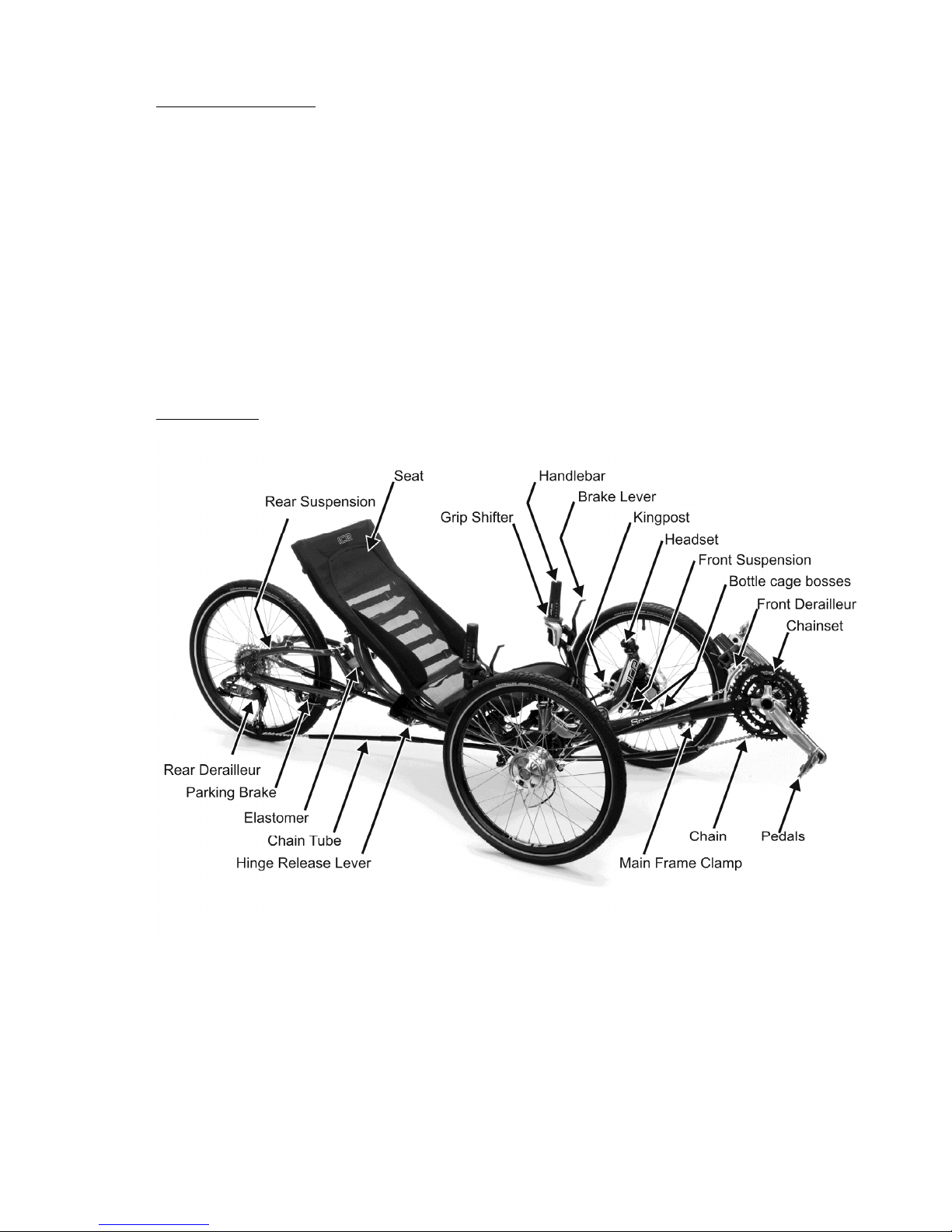
1.1 Overview
Page 4
4
2.0 Assembling your Trike
Assembly tools required:
3mm Hex Key Bicycle pump
4mm Hex Key 8mm wrench
5mm Hex Key
6mm Hex Key
10mm wrench
13mm wrench
Cable cutter Chain link remover
Small flat screwdriver Sharp knife
Torque wrench (optional) T25 Torx key (required for disc brakes)
TIP – You will find it much easier to assemble the trike if you can work on a
bench or a table at waist height; this avoids too much bending down. If you
have to work on the ground, put down some newspaper to avoid the chain,
which is protected by grease, from picking up dirt
Throughout this manual, “left” and “right” are based on the rider’s position, as seated on the trike.
When assembling your trike, please refer to the table in the appendix for the proper tightening torques for all
fasteners. Do not over-tighten.
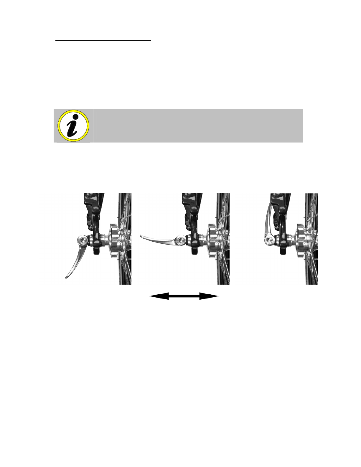
2.1 Adjusting and Closing Quick-releases
Open
Closed
Quick-releases are used in a number of places on your trike; it is important that they are tightened
correctly.
A quick-release that isn’t fully and properly closed can result in parts coming loose or moving while
riding. This could cause a serious accident.
A quick-release system consists of two basic parts: a lever that provides the clamping force and
an adjusting nut that alters the clamping tension.
With the part you are clamping located properly, adjust the quick-release by opening it, holding
both ends and turning one clockwise until, when you close the lever, you feel some resistance. At
this point, try to close the lever fully. The adjustment is correct when you can fully close the lever,
but with some effort (the lever should leave its impression in the palm of your hand). If you can only
close the lever part way, open it, unscrew the adjusting nut slightly and try again. If it closes too
easily, tighten it up a tiny bit and try again. Do not try to tighten the quick-release by winding the
lever around; it will not tighten enough to be safe.
Right…… let’s begin assembly!
Page 5
5
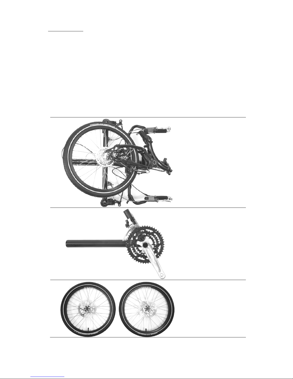
2.2 Unpacking
First of all, open the box, unwrap and lay out the pieces, inspecting for any damage that may have occurred
during shipping.
The black square of fabric-covered rubber is not a piece of packing. Do not throw it away!!
You should have all the items shown below, as well as any accessories you have ordered.
Assembling your trike is quite simple, even if you have done little bicycle assembly/work before. If you’re
uncertain about the work, any decent bike shop will be able to follow these instructions to assemble it for you.
It will take you a under an hour to put your trike together, but don’t be tempted to rush through;
Your trike is secured in the box using several cable ties (zip-ties) which will have to be cut with a knife,
scissors, or snips; be careful not to cut through the parts or to mark the paintwork. Have a good look at the
various packages and familiarize yourself with the various parts. In addition to the main components shown
below, there are other small packages of parts. Don’t open them just yet; leave them sealed until you need
them. (Please note, tyres may be supplied only partially inflated for shipping. Please inflate tires to correct
pressure before sitting on your trike. The correct inflation pressures are printed on the tire sidewalls.)
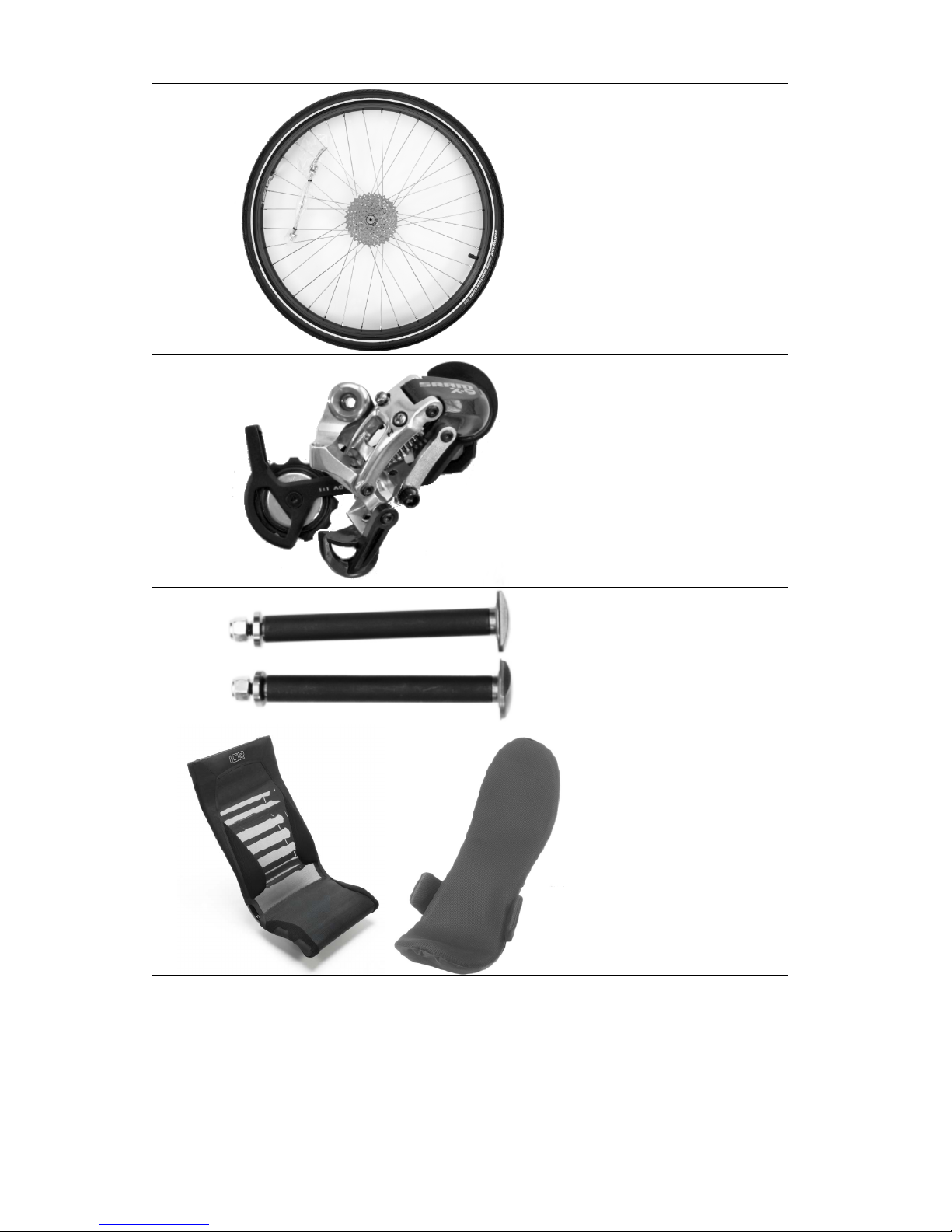
Main frame (cruciform and rear
section)
Front Boom
Front Wheels (disc brake
version shown – wheels are
shipped without rotors
attached to avoid transit
damage).
Page 6
6
Rear Wheel (installed on 20
inch models, supplied
separately on 26 inch models)
Rear Derailleur – attached by
its cable and fastened to the
rear section.
Axle bolts
Seat Cover and Frame (mesh
seat models)
Or
Seat and Cover
(hard-shell seat models)
Page 7
7
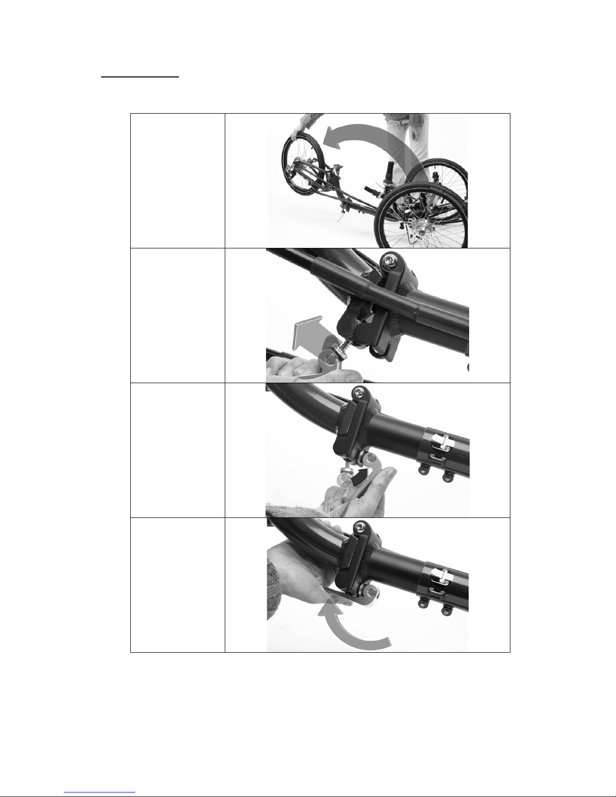
2.3 Unfold trike
Unwrap the trike main cruciform and sit it on a flat surface, preferably with something soft (cardboard/carpet)
under the frame to protect the paint.
Swing the rear
section of the frame
up and to the left and
then down to the
unfolded position.
Lift the QR (Quick
Release) latch to
retract the safety pin,
and close the hinge.
Make sure the safety
pin is properly
engaged.
Swing the QR and its
connecting pin
forwards 90 degrees
(into the slot on the
front part of the
hinge).
Tighten the QR on the
hinge. If the QR is
loose, the adjusting
nut may be tightened
slightly.
If you have ordered a model with a 26 inch or 700c rear wheel, then insert the rear wheel fully in the back of
the frame and tighten the quick release fully.
Page 8
8
2.4 Fit and set the handlebars to an approximate position.
Slacken off the two clamps on the
steerer and adjust the handlebars
to an upright position. The clamps
only need to be lightly tightened at
this stage.
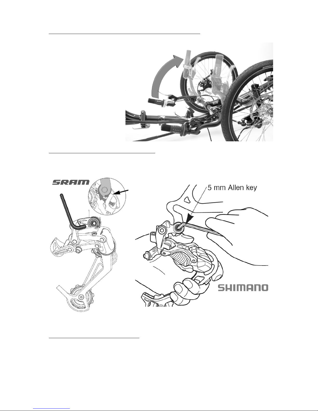
2.5 Install and connect the rear derailleur
The rear derailleur is attached to its cable and loosely fastened to the rear section. Fit the rear derailleur to the
rear dropout using a 5mm hex key, making sure the B-tension washer tab / b-adjust screw is clear of the rear
derailleur dropout tab. Tighten the 5 mm hex hanger bolt to 70 – 85 in. lbs. (8 – 10 Nm).
The derailleur stop screws have already been pre-adjusted in the factory. If you feel the derailleur needs to be
re-adjusted, then please refer to the manufacturer’s instructions sheets packaged with the derailleur.
2.6 Fit the front wheels and brakes
There are 3 different front brake/wheel combinations, depending on which model you have ordered. Identify
which type of wheels & brakes you have, and which are the left-hand and right-hand wheels (they are marked
with a label on the spokes)
Page 9

9
2.6a Fit front AVID BB7disc brake wheels and brakes
The brake calipers have been fastened to the
kingposts, but they need to have the calipers
aligned and the pads adjusted.
Make sure the Caliper Positioning System (CPS)
bolts are loose.
Fit the disc brake rotors to each wheel using 6
bolts per rotor. Set the rotor to rotate in the
direction indicated on the rotor. Tighten the rotor
bolts with a
T-25 Torx bit to 6-7nm or 4.5-5 lb. ft.
Locate the front wheel 12mm axle bolts. Remove the nuts and washers, and partially insert them in wheels
from the outside (the brake rotor is on the inside) so they don’t protrude on the inside of the wheel. Put the
wheel up to the kingpost, sliding the rotor gently into the brake calliper, until the axle bolt is aligned with the
hole in the kingpost. Push the axle bolt through the kingpost and put the washer and the M6 nylock nut onto
the axle bolt which is protruding on the inside of the kingpost. Tighten using a 13mm (1/2”) wrench and a
10mm wrench are needed to tighten the front wheels. After the first time the nut has been installed and
removed, the 13mm wrench will not be necessary; you can lock the axle in place by leaning gently on the
wheel. It is important that these bolts are tight; you will not damage the bearing by tightening to the required
torque.
Repeat the fitting procedure for the other wheel.
The brake cable has been clamped onto the
actuating arm, but it should be checked to
make sure that it is tight. Use the barrel
adjuster at the brake lever to remove any cable
slack. Be careful not to advance the actuating
arm by pulling on the cable.
With the CPS bolts loose, turn the outboard
(closest to the wheel) knob clockwise until it
pushes the rotor into the position shown. This
knob is sometimes quite stiff and a T25 Torx®
key can be used to make it easier to turn. Note
that the rotor should not be centered between
the walls of the caliper body
Page 10

10
Turn the inboard pad adjustment in until it is
firmly squeezing the rotor against the outboard
pad. – this immobilizes the actuating arm. Your
caliper is now in perfect alignment and is ready
to be tightened.
Tighten the 2 caliper positioning bolts (CPS) that
attach the caliper to the mounting bracket.
Tighten one then the other, repeating until they
are at the specified torque.
Turn both pad adjustment knobs
counterclockwise about 2 or 3 click to give
sufficient clearance between the pads and the
rotor. Use the pad adjustment knobs whenever
you need to adjust your brakes (the adjustment
at the brake lever is only for removing cable
slack.
Page 11

11
2.6b Fit front AVID BB5 disc brake
Follow the procedure above up to where the
cable has been clamped onto the actuating arm
then With the CPS bolts loose,
Use your fingers or a Torx® wrench to turn the
outboard pad adjustment knob clockwise until
the rotor is centered in the caliper.
This positions the pads for the next step in the
installation.
Make sure the CPS bolts are loose enough for
the caliper to move freely.
.
Turn adjustment knob until the rotor is centered in the
caliper
Squeeze the brake lever to compress the brake
pads firmly on the rotor. While still holding the
brake lever, tighten the CPS bolts. Once they
are tight you can let go of the lever
Back the adjustment knob off
(counterclockwise) until the rotor spins freely.
Now you can dial the pad in or out until you
find the brake action you prefer (make sure, of
course, that there’s no drag on the rotor). If you
can’t seem to get the feel you like, or the rotor
is dragging, repeat the previous step.
Page 12

12
2.6c Fit front Hydraulic brakes
The disc brake system is supplied fully assembled and bled. It is strongly recommended that you install the
brakes supplied without disconnecting any hoses or attempting to shorten the hose
Fit the disc brake rotors to each wheel using 6 bolts per rotor. Set the rotor to rotate in the direction indicated
on the rotor. Tighten the rotor bolts with a T-25 Torx bit to 6-7nm or 4.5-5 Lb ft.
Locate the front wheel 12mm axle bolts. Remove the nuts and washers, and partially insert them in wheels
from the outside (the brake rotor is on the inside) so they don’t protrude on the inside of the wheel. Put the
wheel up to the kingpost until the axle bolt is aligned with the hole in the kingpost. Push the axle bolt through
the kingpost and put the washer and the M6 nylock nut onto the axle bolt which is protruding on the inside of
the kingpost. Tighten using a 13mm (1/2”) wrench and a 10mm wrench. After the first time the nut has been
installed and removed, the 13mm wrench will not be necessary; you can lock the axle in place by leaning
gently on the wheel. It is important that these bolts are tight; you will not damage the bearing by tightening to
the required torque.
Repeat the fitting procedure for the other wheel.
New brakes are supplied fully retracted with a red
plastic insert between the pads. With a firm grip, pull
the red insert out from between the pads (it just clips
in place).
Do not squeeze the brake lever without the
plastic insert or brake rotor between the
pads. If you do, the brake pistons will be
overextended and you may need a bike shop
to rebuild your calliper.
Check that the calliper clamping bolts are slack then
position the calliper and adaptor bracket between the
rotor and the kingpost.
Align mounting holes with those on the calliper
adaptor and fix calliper adaptor to kingpost with the
adaptor bolts. Use a 5mm Allen wrench to a torque of
11 – 13 Nm ( 8 to 10 Lb ft).
Centre the calliper over the disc rotor by squeezing
the brake lever and holding it on whilst tightening the
calliper clamping bolts to the same torque as the
adaptor bolts.
Once the caliper has been centered check that the
wheels spin freely. Squeeze the levers a few times
and the brake pads will self-adjust.
Warning: If you are not confident servicing or adjusting your
brakes correctly, we strongly recommended that you have a
competent cycle mechanic do the job. Always wear protective
clothing, safety glasses and gloves when servicing this
system.
Page 13

13
2.6d Fit front drum brake wheels
Identify the left-hand and right-hand wheels (the
labels are on tape labels fastened to the spokes).
Locate the front wheel 12mm axle bolts with their
washers and 6mm nylock nuts. Remove the zip tie.
Slide an axle bolt through the hub from the outside of
the wheel (the side with the five webs on the hub
flange),
There is a small spacer inside the hub and it should
be fitted like the one in the picture. (Note the brake
plates are handed, and should be fitted so the brake
lever arm points forward and down towards the
ground. Now slide the bolt with the complete wheel
assembly through the kingpost, locating the single
hole in the black brake plate onto the drum brake pin
as per the picture below.
Put the washer and the M6 nylock nut onto the axle
bolt which is protruding on the inside of the kingpost.
Tighten using a 13mm (1/2”) wrench and a 10mm
wrench are needed to tighten the front wheels. After
the first time the nut has been installed and removed,
the 13mm wrench will not be necessary; you can lock
the axle in place by leaning gently on the wheel.
Before tightening the axle bolt (see table in Appendix
A for torque setting), check that the drum pin is
properly located. It is important that these bolts are
tight; you will not damage the bearing by tightening to
the required torque.
Repeat the fitting procedure for the other wheel.
Make sure the brake plate is located on the pin as this stops the
plate rotating.
This is essential for proper operation of the brake.
Slide the brake cable adjuster
into the lower slot in the brake
plate. The brake cable clamping
barrel has been installed onto
the brake cable, but not
adjusted or tightened. Hook the
barrel over the actuating arm
and pull the slack out of the
cable; clamp the barrel into
place.
Adjust the brake by screwing out
the adjuster until the wheel
starts to drag slightly when
spun. Screw in again slightly
until the wheel runs freely.
Screw down the locking ring
tightly.
Page 14

14
2.7 Seats
Your trike will have been supplied with a mesh or hard-shell seat. There will be 2 plastic clips on the tube on
the underside of the seat, and a top seat mount clipped to the back face of the seat near the top
2.7a Mesh Seat
The mesh seat is supplied with the cover
installed, but not tightened. Tighten the
bottom 5 straps so they are tight. The rest
of the straps can be adjusted to your
preference after you sit on the trike. A
good starting point is to tighten them
gently by pulling the strap held only
between your thumb and forefinger. Be
careful about over-tightening the straps
on the back of the seat; too loose is more
comfortable than too tight. When all the
straps are adjusted, tuck the loose tails
into the clips so they don’t flap about.
2.7b Assembling the seat – hard-shell seat
The hard-shell seat comes fully assembled except for the optional ‘Love Handles’. These should be installed
and adjusted for width by loosening the bolts and sliding them to the required position. To install the
breathable cover, remove the protective paper from the double-faced tape on the seat, put the Ventisit cover
in place and press firmly over the taped areas. The cover will stick in place sufficiently to stop it from sliding
around. The cover can be removed and replaced many times before the tape becomes non-sticky.
2.8 Fit the seat
If you have an ‘Adventure’, you will need
to raise the seat mount extension. Put
the mounting bolts in the position shown
in the photo to the right, and tighten.
Place the seat onto the trike, fitting the
lower seat rail into the seat mount cup
on the frame. Slide the plastic clips
along the lower seat rail and over the
seat mount. Tighten the small knobs
until the clamps are tight (the seat will
still be able to pivot on the mount. The
nuts do not need to be screwed right
down. They are there to prevent the
knob from being unwound too far and
falling out.
Loosen the quick release at the top of
the rear section (or seat mount
extension, if fitted) . Slide the arms of
the top seat mount over the quick
release and tighten the quick release to
hold the seat in position.
Page 15

15
The nuts do not need to be screwed down they should be left
at the end of the screws as seen here.
2.9 Fit the front boom to an approximate position.
Fit the front boom into the frame taking
care not to damage the plastic shim
located inside the front of the main frame.
Position the boom at approximately a
hands span from the base of the front
derailleur post to the end of the main
cruciform.
2.10 Fit the pedals
(Your own if not ordered from us) – Note: the pedal threads are handed. The right hand pedal tightens in the
normal direction; the left-hand pedal has a left hand thread, and tightens in the opposite direction to normal.
Tighten the pedals to the torque shown in Appendix A
2.11 Adjust the seat angle
Check the tyres are inflated and then sit on the trike and decide whether the seat angle suits you. The seat
can be set more upright (it was set to maximum recline in section 2.8) by simply opening the seat mount
quick-release, sliding the seat mount off the quick-release, and slotting it back over using a different set of
slots.
Page 16

16
2.12 Set the handlebars
The handlebars on your trike adjust forward and back, as well as for width. Sit on the trike and adjust the bars
to a position that feels comfortable. Typically, the angle of your elbow joint should be slightly more than 90
degrees open. Check the clearance between your hands and the wheels; also check the clearance between
the brake levers and frame at full steering lock. Adjusting the handlebars to their widest comfortable position
that doesn't interfere with the front wheels will give you the maximum amount of steering movement. Tighten
the handlebar clamps.
Do not use the handlebars to pull yourself out of the trike with; they are
not meant for this purpose. Under normal use the handlebars will not
slip in their clamps, they will however move if subjected to an abnormal
force.
There is also no need to pull on the handlebars when riding. The trike is
easily steered with a light grip of the fingers.
2.13 Set the front boom
With the seat angle and handlebars set, determine the boom position by sitting on the trike and placing your
heel on the pedal. Adjust the boom so that your leg is straight when the pedal is at its furthest away from you.
Set the front boom upright (by eye), and then tighten the 2 clamp bolts.
Check the boom is not
extended past its MIN
INSERT mark.
If in doubt about the
length, set the boom a little
longer than you think may
be required; it will be
easier to shorten the chain
later. Try pedaling without
the chain on to see if it
feels about right.
Page 17

17
2.14 Install the front derailleur cable
The front derailleur cable can be identified by the cable guide tube (chromed ‘noodle’). Pass the cable guide
up through the rear (larger) hole on the underside of the front boom, so that it just pokes out of the hole on the
top face of the boom. NOTE – the “noodle” appears to sit at an odd angle but this is correct and angles the
cable towards the derailleur.
How the cable connects to the front derailleur will depend on the model fitted to your trike. Pull through any
slack cable. While holding the cable taut, turn the shifter through its range of movement to check the cable
moves smoothly and that the cable is properly seated inside the shifter. Run the cable under the cable anchor
washer and hold taut. Tighten the 5 mm hex cable anchor bolt to 5 Nm (44 in.lbs.). Be careful not to crush or
deform the cable.
TIP - Do not trim any cables until you are happy with the various
settings of front boom and gears. The loose end of the cable can be
tightly coiled so that it is out of the way.
Page 18

18
2.15 Check the chain tube lengths
Note: If tightening the plastic clips onto the pulley plate, be careful not to over-tighten the bolts; it is possible
to damage the plastic clips if you do. These clips are pre tightened at the factory and are designed to allow
some movement of the top front and rear tubes for correct chain alignment when in different gears.
Check for clearance
between the chain tubes
and the front chainset. If
the top or bottom chain
tube at the front is too
long, shorten them by
cutting the tube at the
front end to the required
length with a sharp knife.
Page 19

19
2.16 Fit the chain
Note: before doing the next section you will need to have set the boom length as described in section 2.13.
Twist the right hand rear shifter to the “1” position so that the rear derailleur lines up with the largest rear
sprocket. Twist the left hand front shifter to the “H” position so that the front derailleur lines up with the
largest front chainring.
At the front of the trike, pull the top chain through the
top chain tube. Pass the chain through the front
derailleur cage, around the large chain ring and then
connect it to the lower return chain at the front using
the quick connect link. Remove the ‘R’ pin from the top
chain.
Move the chain through the tubes so that the
unconnected end of the chain at the top at the back is
the longer one.
TIP - make sure the chain is correctly routed through the rear derailleur
cage and goes the correct side of the tab on the derailleur cage between
the two jockey wheels.
At the back of the trike, checking that the chain is not
twisted inside the chain tube, (Twist it all the way in
one direction then all the way in the other direction
then bring it back to the middle.) thread the top chain
down over the largest cog of the cassette and through
the derailleur.
Now set the chain to length by removing a section of
chain from between the rear derailleur and the lower
chain tube. Work out how much chain to remove by
taking the end of the chain from the rear derailleur and
pulling it tight so that the cage of the derailleur is under
maximum tension.
Page 20

20
Note: where the end of one chain overlaps the other. Add 1 or 2 links (with the chain on both the largest
sprocket and the largest chainring) to find the correct place to split the chain.
Split the chain with a chain rivet tool and remove the
unwanted section. This should leave just enough slack
so that the rear derailleur jockey wheels are pointing
forward but so that they can still move up a fraction.
Use an R pin to help stop the chain going back up the
chain tube.
Connect the ends of the chain using the quick connect
links supplied. Make sure that the chain is not twisted.
The chain will be quite tight so moving it onto the small
chainring at the front will make connecting the ends
easier.
check that there is not too much slack when using the
smallest chain ring and smallest cassette sprocket.
When using the largest chainring and largest cassette
sprocket there should be just enough slack so that the
rear derailleur jockey can still move up a fraction.
Page 21

21
TIP – get an extra pair of hands to help with this. Make sure that any links
you alter with the chain link remover are not stiff on the rivets. If in doubt,
remove fewer links than you think as removing links is easier than riveting
links back in. Use the quick disconnect link to open the chain and then
punch out links and quick connect back together.
When you've finished adjusting the chain length, check at the pulley plate where the chain enters and leaves
the chain tubes. The plastic clips should be adjusted vertically so the chain is running centrally where it enters
and exits the chain tubes. This is also the position where the chain runs at it quietest.
2.17 Check the gear shifting
While pedalling, shift the chain up and down the chainrings several times to take out initial slack in the cables.
Any slack can be removed by adjusting the barrel adjuster on the shifters.
Shift the chain to the smallest rear cog. While turning the pedals, move the shifter up 1 click, to the “8”
position. If the chain hesitates or does not shift to the second cog, increase the cable tension by turning the
shifter barrel adjuster counter clockwise. If the chain shifts beyond the second cog, decrease the cable
tension by turning the shifter barrel adjuster clockwise.
Repeat the two former steps until shifting and cable tension is accurate.
It is not enough that the chain should run quietly in each gear, it should also move smartly from one sprocket
to the next, without clattering or jamming.
Now check for smooth changing up through the range, checking one pair of sprockets at a time (8-7, 7-6, etc.)
Make any minor adjustments by turning the shifter barrel adjuster. Finally, check that the chain cannot jump
off the cassette, either on the inside into the spokes, or on the outside onto the dropout. This is adjusted
using the high and low limits screws as shown in the manufacturer’s supplied instructions.
Cut the cable off leaving about 3” (75mm) past the cable clamp, and crimp the cable end cover onto the cable
end.
Page 22

22
2.18 Fit the mirror
The mirror comes with instructions showing
how it is to be assembled. The mirror is
mounted in the top of one of the handlebars
(right handlebar if you drive on the left, left
handlebar if you drive on the right). A plastic
plug is provided for the opposite handlebar.
Many people prefer to ride with a mirror both
sides.
If you have bar-end shifters, you will have a
mirror mount on the handlebars. Insert the
mirror into the end of the mirror mount and
tighten.
2.19 Fit the flag
Place the flag in the flag holder hole in the left or right
side at the top of the seat frame.
If you have a hard shell seat, the flag mounts in
the tube on the back of the seat.
2.20 Reflectors and Bell
Reflectors and a bell are supplied with your trike. The bell can be mounted anywhere on the handlebars
where it can be reached easily and doesn't interfere with steering the trike. The reflectors have brackets
which allow the front reflector to be mounted on the front derailleur post, and the rear reflector to be mounted
on the top rail of the seat.
2.21 Check nuts and bolts
Generally, check all nuts, bolts and quick-releases to make sure everything is tight.
3.0 Other Important Information
3.1 Adjusting the tracking
The tracking on your trike is pre-adjusted at the factory, and should not normally need checking. If you
experience abnormal tyre wear, you will find the instructions for checking and adjusting the tracking in the
Owner’s Manual
3.2 Serial Number
The serial number is marked on the underside of the main cross joint.
Page 23

23
3.3 Warranty Information
Warranty
Inspired Cycle Engineering warrants, to the original owner of each new ICE tricycle that the frame, seat, and
steering components are free of defective materials and workmanship for three (3) years from original date of
purchase. Component parts are limited to one (1) year from original date of purchase. Warranty is conditional
upon the trike being operated under normal conditions and being properly maintained. Warranty is offered to
the original owner only, and is not transferable. This warranty does not apply to:
damage through normal wear and tear
neglect (inadequate care and maintenance)
damage from crashes or jumping
overloading through excess weight
incorrect assembly
modifications to the trike (additional or changed components)
theft
use as a power driven vehicle
failure to follow instructions or warnings in the owner’s manual
Activities for which they were not designed.
Bending of frames, forks, handlebars, seat posts or wheel rims can be a sign of misuse or abuse.
Inspired Cycle Engineering reserves the right to make sole determination of whether any failure or damage
claimed under warranty was caused by material or manufacturing defect, and reserves the sole discretion to
repair or replace any parts covered by this warranty.
The owner shall be responsible for all labour, shipping, and travel costs connected with the repair or
replacement of warranted parts. Inspired Cycle Engineering will, at our sole discretion, normally consider
compensation for reasonable labour, shipping, and travel costs associated with warranty claims.
Inspired Cycle Engineering shall in no event be liable for incidental or consequential losses, damages or
expenses in connection with its tricycle products.
In practice, if you think you have a warranty claim, contact your dealer or us. We are passionate about
our product, and want you to be too. If it is our problem, then we do our best to put it right.
3.4 Liability Information
Liability Waiver:
Taking part in any sporting activity can result in injury or death. Cycling is no different in this regard, and
recumbent tricycles no different from upright bicycles. In many ways, recumbent trikes can be much safer
than a standard bicycle. Nevertheless, the rider (that’s you) is expressly assuming the risk for any injury and/or
property damage that may result from using our product, as well as for any and all injuries and/or property
damages caused by someone riding your trike.
We have no control over how the trike is used or maintained. It’s your trike; it is up to you to be responsible for
yourself. You need to ensure that the trike is safe each time before you ride it. You need to ensure that it is
maintained to a proper standard. Read and understand the supplied manuals; they have warnings and
suggestions that will help you to use the trike safely. If you are in any doubt about any of the advice or
procedures in this manual, please contact your dealer or ICE. It is up to you to know and obey traffic laws of
the country or state where you will be riding your trike. Pedal cycles are regarded in most countries as
vehicles when on the road and are subject to the same rules as motor vehicles. If you are not comfortable on
the road, or have little experience riding in traffic, try practicing riding on quieter streets, at least until you
develop the necessary skills and road awareness. Many bike shops can offer instruction on advanced riding
techniques. Inspired Cycle Engineering shall in no event be liable for incidental or consequential losses,
damages or expenses in connection with its tricycle products.
3.5 Legal requirements
Legal requirements vary from country to country and you should always comply with them.
The important areas you need to consider are lighting, and helmet use. Consult your local bike dealer for
information about what is required in your area. Please also remember that even if not required by law, some
equipment (such as helmets and lights) can increase your personal safety and should be carefully considered.
Page 24

24
3.6 Contacting us
Your first point of contact should be your local dealer. They will be able to answer most of your questions and
can provide you with the full line of ICE accessories. If you need to speak to us directly, we can be contacted
in a number of ways:
In person or by post
Inspired Cycle Engineering Ltd
Unit 9, Spencer Carter Works
Tregoniggie Industrial Estate,
FALMOUTH,
Cornwall TR11 4SN
England
Telephone: 01326 378848 (+44 1326 378848 outside UK)
FAX: 01326 379879 (+44 1326 379879 outside UK)
e-mail: sales@icetrikes.co
Website: www.icetrikes.co
Skype: inspired_cycle_engineering_ltd
Manual Revision: 21 April 2011 V4
Page 25

25
Appendix A: Tightening torques
Fastener Uses Hex Key (mm) nm Lb-ft
Front derailleur clamp bolt 5 5-7 4-5
Front derailleur cable clamp bolt 5 5-7 4-5
Chainset - central crank bolt 8 35-50 25-36
Chainset - chainring bolt 5 + tool 8-10 6-7
Pedals 15mm spanner 35-55 25-39
Chainring guard bolt 5 6-8 4.5-6
Main frame clamp bolts 5 8-10 6-7
Mudguard adjusters 4 6-8 4.5-6
Mudguard main fasteners 5 8-10 6-7
Axle bolts 10mm spanner 8-10 6-7
Steerer pivot bolt 5 8-10 6-7
Handlebar clamps 5 5 4
Twist-grip clamp bolt (hex key) 3 1-2 1-2
Brake lever clamp bolt 5 6-8 4.5-6
Rear main frame joint 5 8-10 6-7
Mirror 3 3-5 2.5-4
Pivot pin clamp bolts 5 6-8 4.5-6
Shock pin 6 5-7 4-5
Disc brake caliper mount 5 6-8 4.5-6
Disc brake rotor lock ring Tool 40 30
Rear mech hanger 5 8-10 6-7
Rear derailleur mounting bolt 5 8-10 6-7
Rear derailleur Cable clamp bolt 5 5-7 4-5
Upper seat mount clamp bolts 4 5-7 4-5
Head rest clamps 4 5-7 4-5
Headrest clamp pin 5 5-7 4-5
Disc Screws T-25 6 -7 4.5-5
Master Cylinder Clamp Screw T-10 1.7 - 2.3
Caliper Bleed Screw 8mm spanner 3 - 5 2.5-4
Caliper Mounting Bolts 5 11 - 13 8-10
All other M4 bolts, tighten to 5-6 nm (4-5 lb-ft)
All other M5 bolts, tighten to 6-8 nm (4.5-6 lb-ft)
All other M6 bolts, tighten to 8-10 nm (6-7 lb-ft)
Page 26

26
Appendix B: Elastomer limits
Rider weight Elastomer
60-128lbs (4-9 stone, 27-58kg) Yellow
120-220lbs (8.5-15.5 stone, 54-100kg) Red
148-275lbs (10.5-19.5 stone, 67-125kg) Green
Your elastomer will also depend on your riding style, terrain and other factors. If you ride on rough terrain or ride
aggressively, you may benefit from a harder elastomer. If you are a leisurely rider, who rides predominantly on smooth
tarmac, you may be able to use a softer elastomer. Note: you may need an elastomer that is one grade harder if you are
carrying any significant load.
If you are a light rider and have your suspension setup soft it is advisable to adjust it to a firmer setting and change for a
harder elastomer if necessary before allowing a significantly heavier rider to sit on your trike, otherwise permanent damage
to the elastomer may occur.
Appendix C: Tyre Pressures
PSI BAR PSI
2 29.0
30 2.1
2.5 36.3
40 2.8
3 43.5
50 3.4
3.5 50.8
4 58.0
60 4.1
4.5 65.3
70 4.8
5 72.5
80 5.5 80.0
6 87.0
90 6.2
6.5 94.3
100 6.9
7 101.5
7.5 108.8
110 7.6
8 116.0
120 8.3
8.5 123.3
130 9.0 130
9.5 137.8
140 9.7
 Loading...