

Page 1
INDUSTRIAL CONTROL COMMUNICATION
Communication Node
for EMS/BMS
Installation Instruction Manual
Models
Ethernet (ETH-1000) for BACnet IP
and Modbus TCP
Control
Serials
Mirius (Serial RS-485) for BACnet MS/TP)
and Modbus RTU
Energy Management System
Building Management System
Installation
PRINTED 0419
100318030 2000571701 (Rev. A)
Page 2

CONTENTS
INTRODUCTION ........................................................................... 3
Warnings ...................................................................................3
Parts ..........................................................................................3
Tools Required ..........................................................................3
General Guidelines ...................................................................3
FEATURES AND COMPONENTS ................................................ 5
DEVICE CONFIGURATIONS ........................................................ 6
ETH-1000 Wiring .......................................................................6
Mirius Wiring .............................................................................6
INSTALLATION CONSIDERATIONS ............................................8
Touch Screen Style Display Installation ....................................8
High Efciency Water Heater Installation – (BTH Or BTX
Models) ................................................................................. 8
Commercial Electric Water Heater (Touch Screen
Installation) ........................................................................... 8
Membrane Switch Style Display Installation ..........................10
High Efciency Water heater Installation ............................ 10
Commercial Electric Water heater Installation .................... 10
Boiler Installation .....................................................................12
XP XWH Boiler Installation ................................................. 12
ECC DEVICE VERSIONS ........................................................... 13
BACnet / Gas Water Heaters ..................................................13
Product Description ............................................................ 13
Protocol Implementation Conformance
Statement (PICS) ............................................................... 14
BACnet Standardized Device Prole (Annex L): ..................... 14
BACnet Interoperability .............................................................14
Segmentation Capability ...........................................................14
Data Link Layer Options ............................................................14
Device Address Binding ............................................................14
Character Sets ..........................................................................15
Data Types ................................................................................15
Object Types and Properties .....................................................16
Device Object Listings ........................................................ 16
Object Min/Max Values .............................................................16
BACnet/Gas Water Heaters Object List ....................................17
Central Control Board Major State Denitions ..........................20
Xi 1.0 Energy Management System (EMS) Control .................. 20
Mxi Energy Management System (EMS) Control .....................21
Fault Codes and Warnings ........................................................22
BACnet / Electric Water Heaters ............................................23
Product Description ............................................................ 23
Protocol Implementation Conformance
Statement (PICS) ............................................................... 23
BACnet Standardized Device Prole (Annex L): ....................... 23
BACnet Interoperability ............................................................23
Data Link Layer Options ............................................................24
Device Address Binding ............................................................24
Networking Options ...................................................................24
Character Sets ..........................................................................24
Data Types ................................................................................25
Object Types and Property Support ..........................................25
Device Object Listings ........................................................ 26
Device Objects Initial Values .....................................................26
Device Objects Minimum/Maximum Values ..............................26
Central Control Board Major State Denitions ..........................30
Energy Management System (EMS) Control ............................ 30
Fault Codes and Warnings ........................................................30
BACnet / Boilers ......................................................................32
Product Description ............................................................ 32
Protocol Implementation Conformance
Statement (PICS) ............................................................... 32
BACnet Standardized Device Prole (Annex L): ...................... 32
BACnet Boiler Interoperability ...................................................32
Segmentation Capability: ..........................................................32
Data Link Layer Options ............................................................33
Device Address Binding ............................................................33
Character Sets ..........................................................................33
Data Types Supported...............................................................33
Boiler Device Object Types/Property Support ..........................34
Object Listings .................................................................... 34
Boiler Device Object Initial Values ............................................34
Boiler Device Object Min/Max Values .......................................35
Boiler Slave States ....................................................................36
Boiler Modbus Register Access ................................................36
Boiler Modulating Sensor Select/DHW Demand Switch ...........37
Lock and Hold Codes ................................................................37
Modbus / Gas Water Heaters .................................................44
Product Description ............................................................ 44
Modbus Gas Water Heater Register Listings ..................... 44
Modbus Gas Water Heater Register Properties ........................44
Central Control Board Major State Denitions ..........................47
Xi 1.0 Energy Management System (EMS) Control .................. 47
Mxi Energy Management System (EMS) Control .....................47
Fault Codes and Warnings ........................................................48
Modbus / Electric Water Heaters .............................................49
Product Description ............................................................ 49
Electric Water Heater Register Listings .............................. 49
Modbus Electric Water Heaters Register Properties .................49
Central Control Board Major State Denitions ..........................52
Energy Management System (EMS) Control ............................ 52
Fault Codes and Warnings ........................................................52
ICC PROGRAM INFORMATION ................................................. 53
2
Page 3
INTRODUCTION
New building construction and energy saving techniques have
driven the need for improved communications between appliances
and building environmental systems. There are several different
protocols that have developed for accomplishing this task
including BACnet and Modbus. Since appliances come with a
variety of controls, interfacing with the various protocols presents
different challenges.
Industrial Control Communications (ICC) has developed the
devices to act as a communication gateway allowing appliances
to communicate to the different building management protocols.
The ICC module translates the appliance codes and commands
into the appropriate protocol language giving the end user the
ability to monitor and control the appliance. The end user will be
able to adjust and monitor the equipment and obtain better levels
of efciency and cost savings.
The ICC module in this kit has been designed to seamlessly
integrate with the water heater controls. Once the unit is
connected to the control and to the energy management system,
the user will be able to operate the unit with the Building
Management system interface.
WARNINGS
When installing the unit, ensure that all power is off before
opening any water heater enclosure. Failure to do so could result
in electrical shock and/or possible damage to the unit.
Do not install in areas of high temperature, in excess of 167° F.
Install in areas not subject to water or excess moisture.
PARTS
Table 1. Parts Required
Item Ethernet Serial (RS-485)
ICC Module X X
Communication Cable X X
Power Adapter X X
Jumpers 4 4
Splitter X X
USB Key X X
lists and instructions required to install and congure to your water
heater/boiler and BMS system.
Before plugging in the ICC Gateway, install the ICC Conguration
Studio from the USB key and run the program. Once running,
select File, Open Project and browse to the USB key and select
the conguration le whose name matches the gateway,
Because some USB hubs may not supply sufcient current to run
the Gateway, insure that the ICC Gateway is connected to the
power adaptor. Then connect the ICC Gateway using the USB
cable provided. Run the ICC Gateway Studio application from the
start menu.
Each conguration has default address and BACnet instance
settings that can be changed. For Mirius gateways, the default
Modbus address is 1 and the default BACnet address is 81. For
gas models the default BACnet Instance Number is 520081 and
for electric models the default instance number is 530081. For
Ethernet Gateways, the default setting is to acquire an IP address
automatically from the router (DHCP). If a static IP address is
desired this can also be set. To change these addresses and
communication settings, use the ICC Conguration Studio
application program. The latest version of this application program
can be downloaded from:
www.iccdesigns.com/icc-conguration-studio.html
Before making any changes, it is recommended to save the
installed conguration project using the disk icon or File -> Save
Project As, then give it a name and select the folder, nally press
Save.
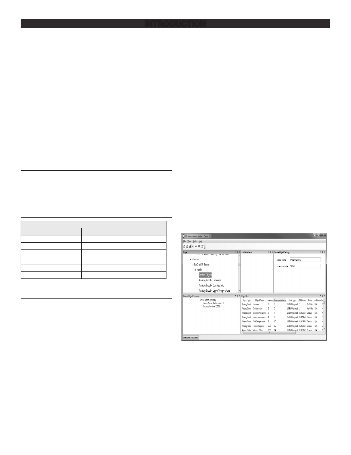
To change the Instance number and the Device Name, scroll
down and select the Device Object and replace the text in the
boxes in the upper right corner.
TOOLS REQUIRED
Wire Cutters
24 AWG Wire Stripper
2.5 mm Flat Blade Screw Driver
GENERAL GUIDELINES
The module should be installed as close as practical to the water
heater control.
The ICC module uses a 120 Volt power adapter to supply 9 volts
DC for the unit. One 120 VAC outlet is required for each module
installed. The power adapter comes with a six foot length of wire.
If additional wire is needed, extra wire may be added, in
accordance with local ordinances for installation of low voltage
wire.
The ICC Gateway kit contains a USB key with the ICC
Conguration Studio program, all conguration les, parameter
Figure 1. Changing Instance Number and Device Name
For ETH-1000 (Ethernet interface) the IP settings, including
DHCP/Static, the IP address and authentication can be changed
by selecting Ethernet from the upper left hand window and
changing the text and drop down list selection similar to changing
the Instance number above.
For Mirius (RS-485 A interface for BACnet MS/TP or ModBus
RTU), the baud rate and other serial communication parameters
can be changed by scrolling down to and selecting RS-485 A ->
ModBus RTU Slave.
3
Page 4
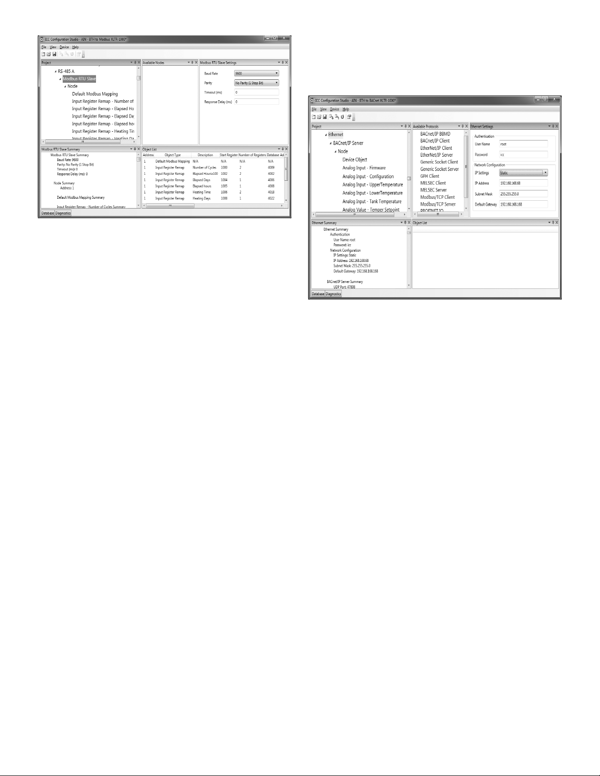
Figure 2. Changing ModBus Parameters
The ModBus address can be changed by selecting Node under
the RS-485 A -> ModBus RTU item.
Likewise for BACnet, the baud rate and other serial
communication parameters can be changed by scrolling down to
and selecting RS-485 -> BACnet MS/TP Server. The BACnet
MAC Address can be changed by selecting Node under the
RS-485 A->BACnet MS/TP Server.
Warning: Do not change any other values other than these or the
gateway conguration may not function properly. In this
case, the le saved above can be reloaded to start over.
When changes are complete press the Download Conguration icon:
Figure 3. Changing BACnet Parameters
4
Page 5
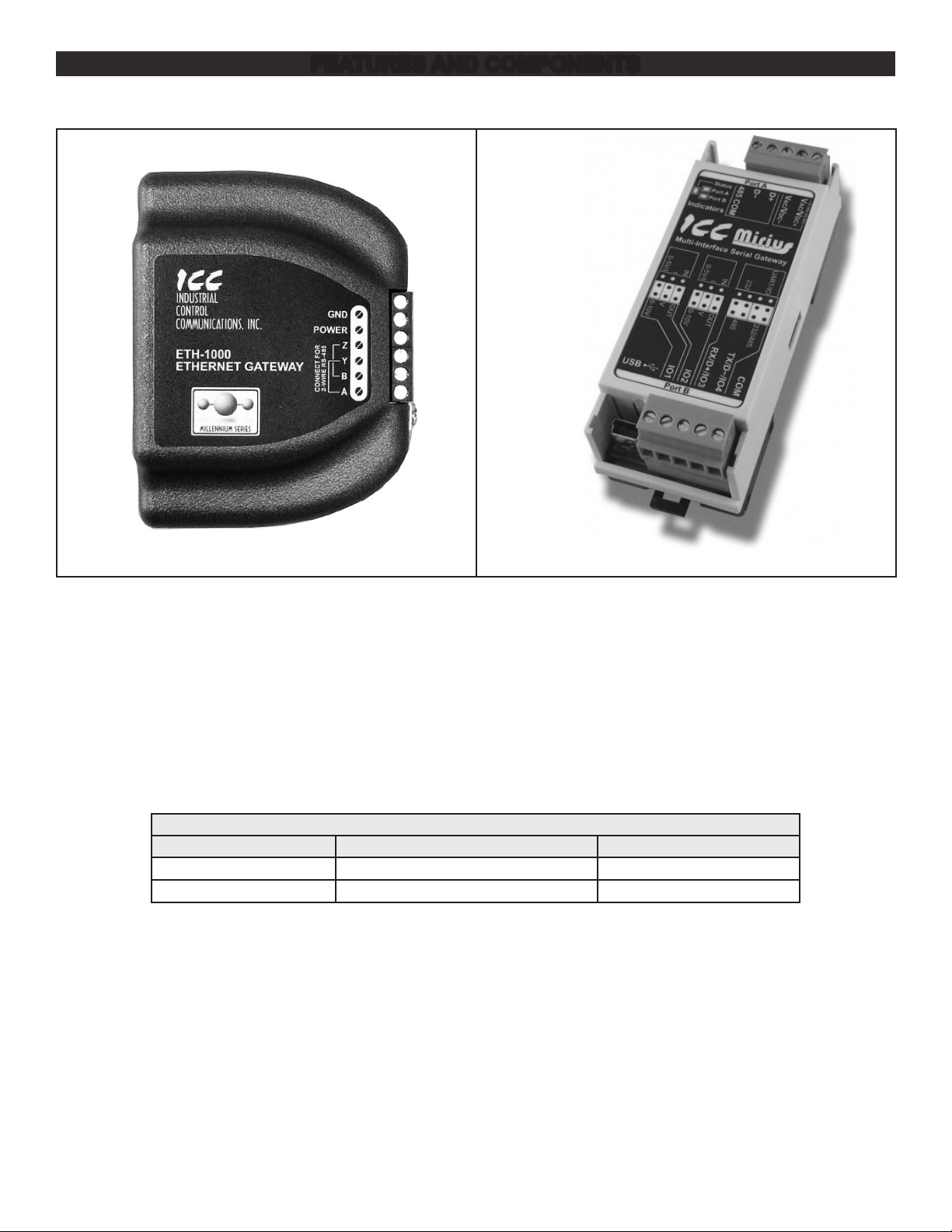
FEATURES AND COMPONENTS
Figure 4. ICC ETH-1000 (Ethernet) Version
• Works with Cyclone (BTH, BTX-100, BTXL-100, DVE, DSE/
DVE/DHE
• Use the ICC Control to enable/disable the water heater.
• Change Temperature Set points and differentials.
• Two models with four different congurations to connect to
BACnet and Modbus.
• Ethernet and Serial RS-485 versions available.
• Two-wire or four-wire RS-485 versions available.
Table 2. ICC Versions
Kit Connection Part Number
Mirius Serial - RS485 (RTU/MS/TP) 100316044
ETH-1000 Ethernet - RJ-45 100316045
Figure 5. ICC Merius Serial RS-485 Version
• Power can be supplied via the USB cable, as a 7-24 VDC
input on the main termainal block, or via IEEE 802.3af Power
over Ethernet (PoE on ETH-1000 only).
• Congure protocols, network characteristics, and client/server
object denitions.
• Graphically interact with the interal database in real-time via
the USB connection.
• Automatically discover and congure IP settings Ethernet
gateways connected to the current subnet.
• Update rmware.
5
Page 6
DEVICE CONFIGURATIONS
Brown/White Wire*
Jumper
Brown Wire*
Blue/White Wire*
From 9 VDC Power Adapter Cable
Power
Power
Jumper
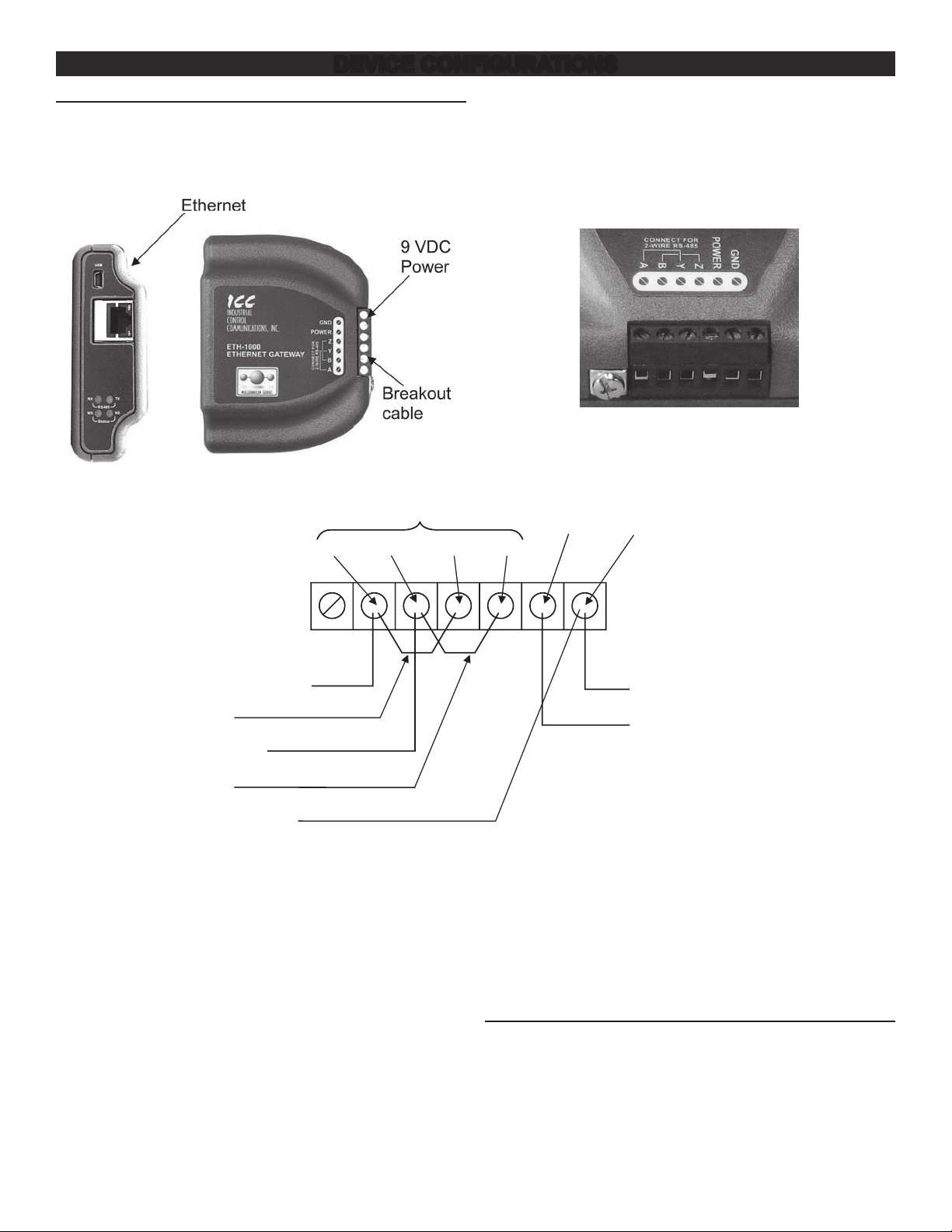
ETH-1000 WIRING
Figure 6 shows the standard conguration of the Ethernet modules.
The module has connections for 9 VDC power, three wire
connections for the communication cable, and a port for the
connection of the EMS system through Ethernet RJ-45 cable or
serial communications.
Figure 6. Standard Conguration for Ethernet Modules
Connecting of the power adapter and the boiler or water heater
communication cable to the module is accomplished on the same
end of the unit. Figure 7 is a close up of the connection terminal
and Figure 8 shows the appropriate connection to the strip using
the power adapter and communication cable.
The provided communication cable has two RJ-45 plugs.
Remove one with a wire cutter, then locate and strip the 3 wires
described below and strip 1/2 inch of insulation before connecting.
Figure 7. Connecting the Power Adapter
The connections in Figure 8 are the same regardless of the
appliance or the communication protocol.
At the opposite end of the module is the connection location for
the EMS LAN connection. The EMS uses an Ethernet connection
with an RJ-45 connector. Plug the cable into the RJ-45 receptacle.
When connecting the RS-485A connections, please note the
following:
For 2-wire systems, jumper terminal A to Y. Also jumper B to Z.
Connect the RX/TX+ (plus) wire from your Building Management
System to terminal A/Y. Connect the RX/TX– (minus) wire from
your Building Management System to terminal B/Z.
AB YZ
*From Communication Cable
†
Figure 8. Connections from the Communications and Power Adapter Cables
RS 485
Pos
GND
Black Wire
†
Black/White Wire†
For more information on connecting the ICC Gateway to your
Building Management System, please refer to the User Manual
provided on the enclosed USB key in the “Documents” folder. The
two applicable documents will be found in the Manuals.
MIRIUS WIRING
Figure 9 shows the he standard conguration of the module. Port A
of the module has connections for 9 VDC power, three wire
connections for the communication (breakout) cable, for Serial
communications to the water heater/boiler.
Figure 10 is a close up of the connection terminal and Figure 11
shows the appropriate connection to the strip using the power
adapter and communication cable.
6
Page 7
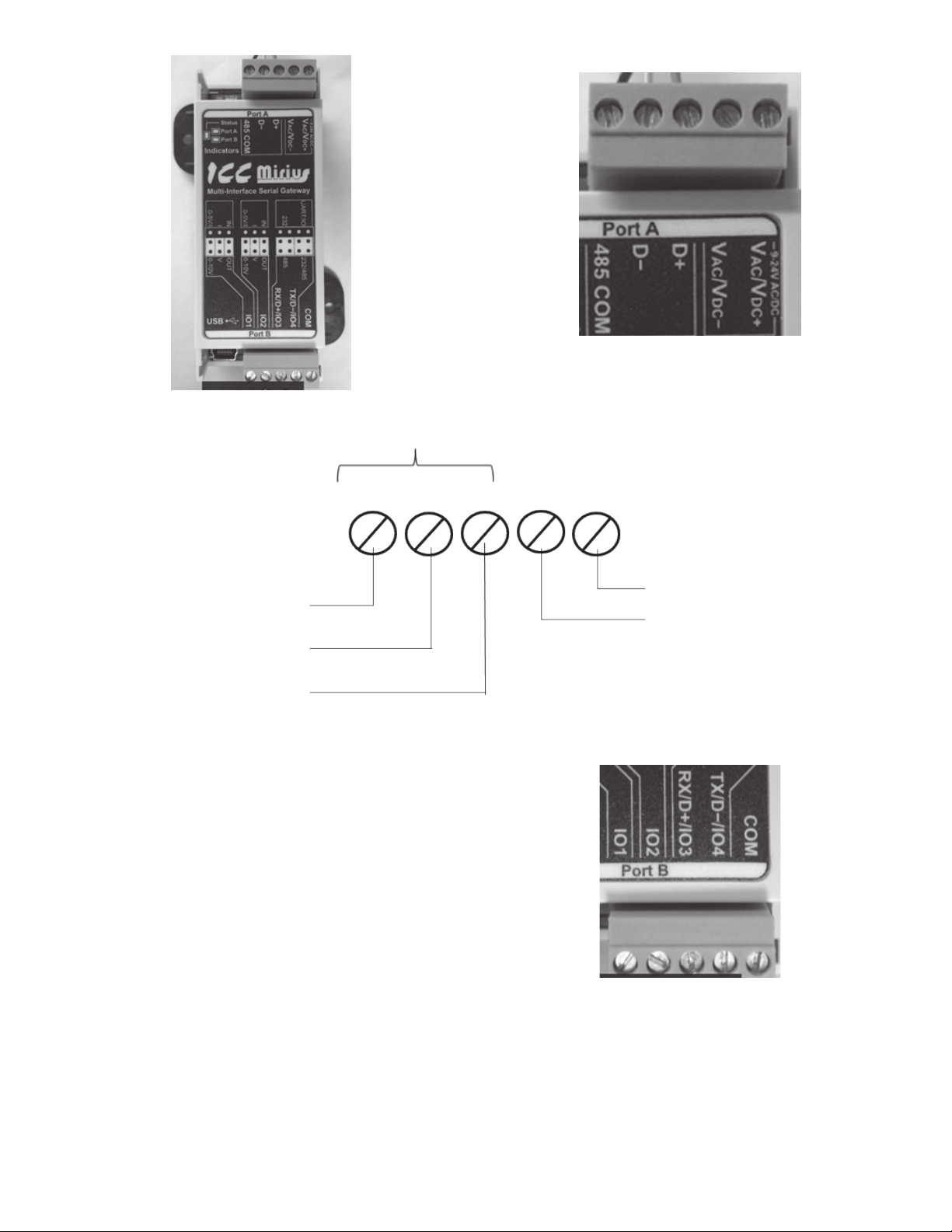
Figure 9. Mirius Unit with Communications Terminal
RS485
* From Communicaon Cable
Figure 10. Close-Up View of Connection Terminal
The provided communication cable has two RJ-45 plugs.
Remove one with a wire cutter, then locate and strip the 3 wires
described below and strip 1/2 inch of insulation before connecting.
COM
Blue/White Wire*
Brown Wire*
Brown/White Wire*
†From 9VDC Power Adapter Cable
Figure 11. Mirius Wiring Schematic
The connections in Figure 11 are the same regardless of the
appliance or the communication protocol.
At the opposite end, Port B of the module is the connection
location for the EMS/BMS connection. See Figure 12. For
connections to the terminal use the labeling on the module as a
guide.
When connecting the RS-485A connections (BACnet or Modbus)
please note the following:
• Only 2-wire systems are supported
• Connect the RX/TX+ (plus) wire from your Building
Management System to terminal RX/D+. Connect the RX/
TX– (minus) wire from your Building Management System to
terminal TX/D-.
B
Power
GND
A
Power
POS
Black/White Wire†
Black Wire†
Figure 12. Mirius Port B Terminal
7
Page 8
INSTALLATION CONSIDERATIONS
There are two types of displays to consider when installing the
ICC gateway modules to the water heaters, the older type with
membrane switches and the newer style with a touch screen. The
new touch screen style display does not need the provided
RJ-485 splitter and it can be discarded.
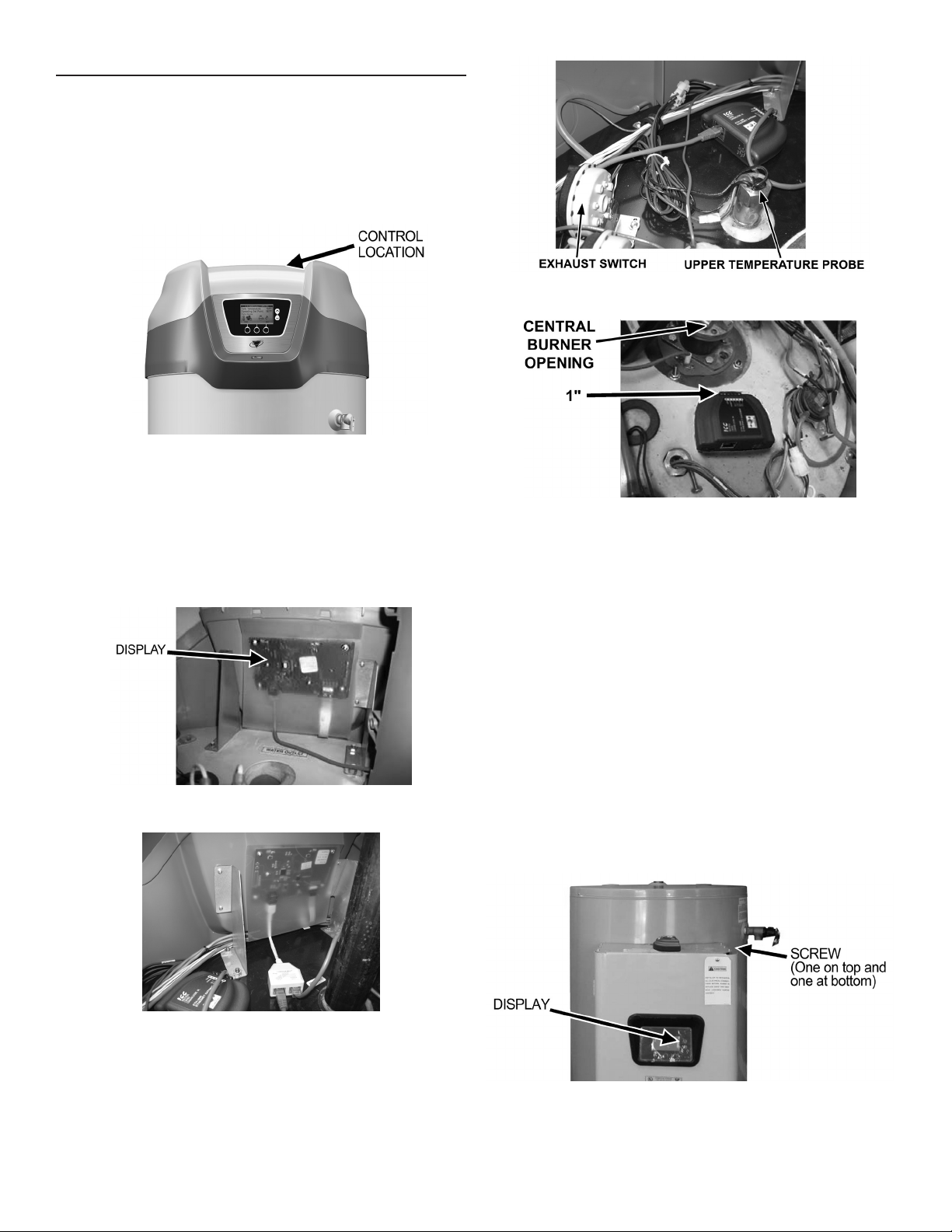
TOUCH SCREEN STYLE DISPLAY INSTALLATION
HIGH EFFICIENCY WATER HEATER INSTALLATION – (BTH OR BTX MODELS)
Follow the directions under general guidelines for connecting the
module to the Energy Management System and power. This
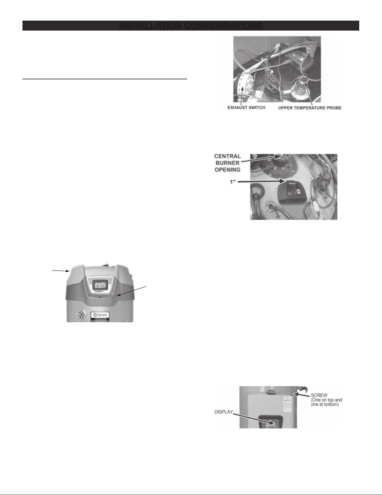
section will guide the installer on how to mount and connect the
module to the water heater. The control box and mounting location
on the water heater is on the top of the unit behind the display
module. See Figure 13.
Connection of the RJ-45 end of the communication cable to the
heater is required to plug into J13 of the control board inside the
“black controls box” (for newer models) requiring removal of two
screws holding the lid on. After plugging in the communications
cable, route the cable to the bottom side with the other cables and
put the lid back on with the two screws.
If the control board is in a “grey controls box” (for older model),
double check to make sure the display is not one with membrane
switches below and to the right of the display. If the display uses
membrane switches, please follow directions under the section
“MEMBRANE SWITCH STYLE DISPLAY INSTALLATION”. If it
has a grey box and is a touch screen display (replacement of
original) then the communications cable must be plug inside the
box to J9 or J10. This will require removal of the two screws
holding the lid on. After plugging in the communications cable,
route the cable to the right side with the other cables and put the
lid back on with the two screws.
Top
Control
Location
Figure 13. Controller Location (BTH or BTX models)
Removal of the top is not required, but it may be helpful to remove
the control box lid. Use a ladder to access the top of taller water
heaters.
Next locate the upper temperature probe and exhaust switch.
Position the module between the two about 1 inch from the central
burner opening. For the 500 MBTUH Model this would be next to
the upper temperature probe.
Figure 14. Location of Exhaust Switch and Upper Temperature Probe
Connect the three wires from the end of the communication cable
to the module in Accordance with page 4. Once the unit is
installed and connected, the building management system can be
connected to the appropriate connection point on the module.
Figure 15. Clearance of ICC Unit from Central Burner Opening
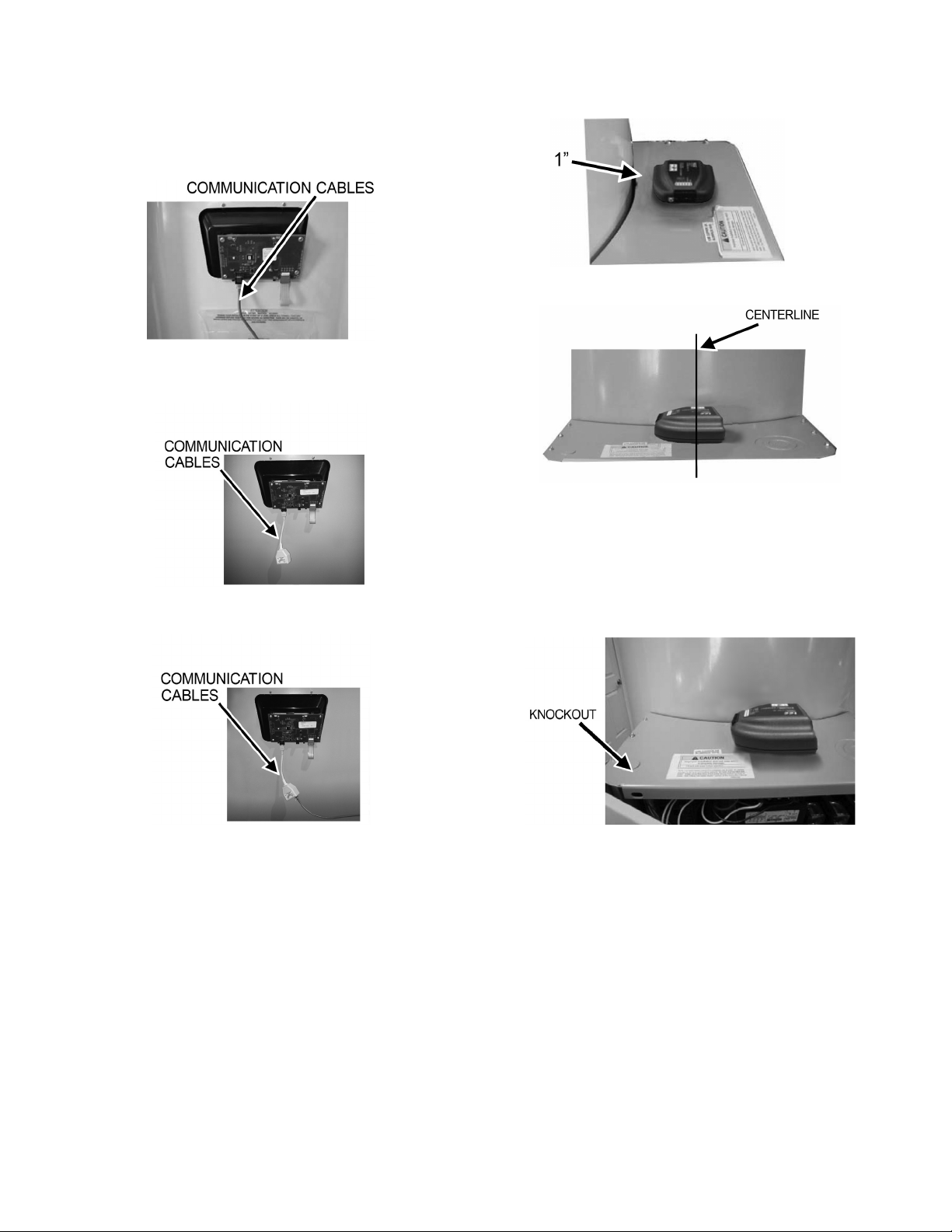
COMMERCIAL ELECTRIC WATER HEATER (TOUCH SCREEN INSTALLATION)
Normally the commercial electric heaters have a display with
membrane switches, but may have had a replacement touch
screen or future models may one day include touch screens. If
this heater has membrane switches on the bottom and right of the
display, then see the section below COMMERCIAL ELECTRIC
WATER HEATER INSTALLATION.
Follow directions under general guidance for connecting module
to the Energy Management System and power. This section will
guide the installer on how to mount and connect the module to the
water heater.
The module should be located where it will not interfere with the
door or in a location that is acceptable to the customer. Care
should be exercised to avoid drilling the self-tapping screws into
electrical or sensitive components. Electrical power should be
disconnected before proceeding with ICC installation.
Using a flat blade screwdriver, loosen the screws holding the door
of the unit. See Figure B1. Swing the door to the open position
and locate the control board.
Figure 16. Opening the Control Board Compartment Door
Locate the module on the top of the door cabinet approximately 1
inch from the water heater jacket and on the centerline of the unit
(See Figure 17 and Figure 18).
8
Page 9
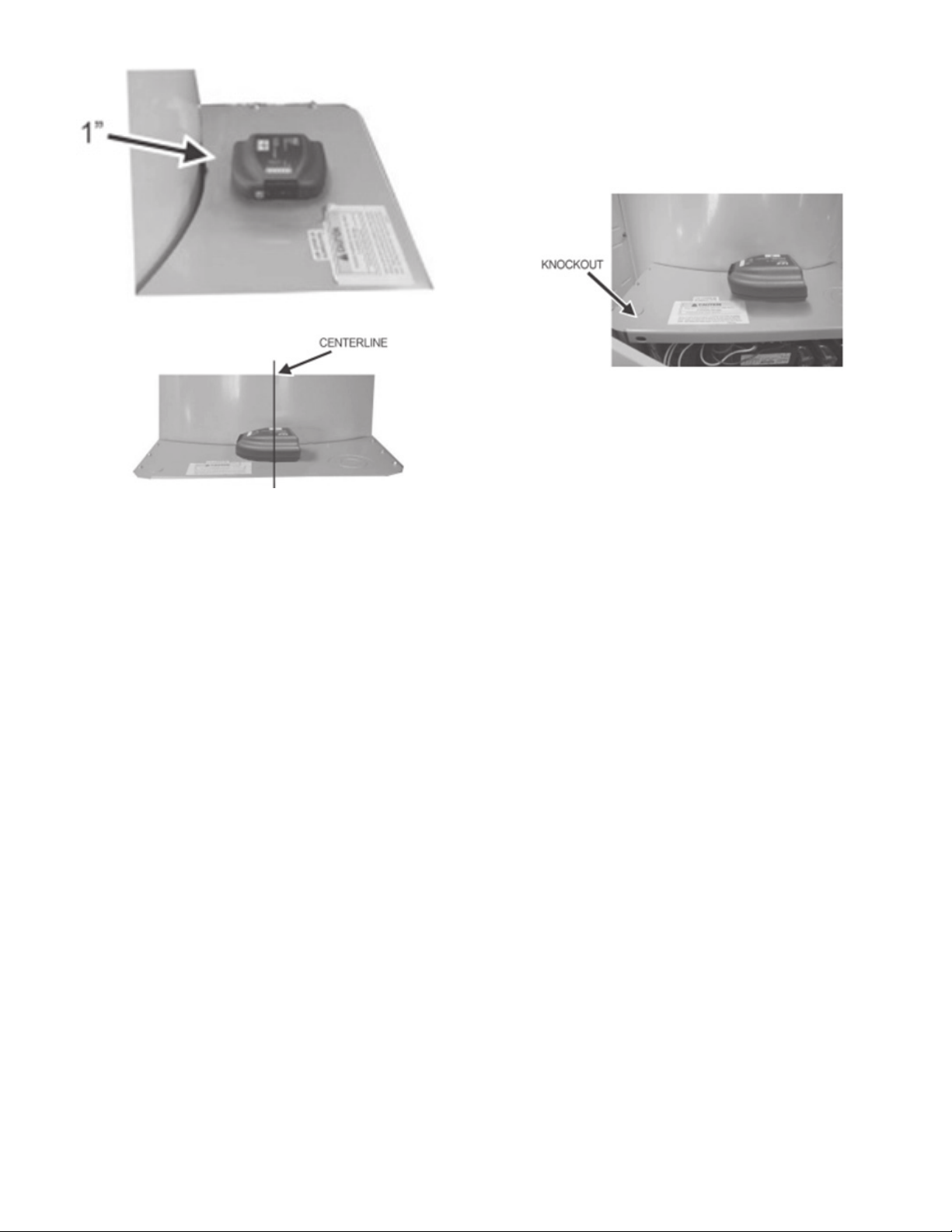
Figure 17. ICC Location Relative to Water Heater Jacket
Figure 18. ICC Location Relative to Centerline
Remove the hole plug from the 0.875” knockout on the left corner
of the top panel. See Figure 19.
Plug the communications cable into D9 and run the three wire
connection up through the knockout and connect the three wires
to the module as shown on page 4. Once the unit is installed and
connected, the building management system can be connected to
the appropriate connection point on the module.
Figure 19. Location of Communications Wiring Knockout
9
Page 10
MEMBRANE SWITCH STYLE DISPLAY INSTALLATION
HIGH EFFICIENCY WATER HEATER INSTALLATION
Follow the directions under general guidelines for connecting the
module to the Energy Management System and power. This
section will guide the installer on how to mount and connect the
module to the water heater.
The control box and mounting location on the water heater is on
the top of the unit behind the display module. See Figure 20.
Figure 20. Locating the Control Box
Removal of the top is not required. Use a ladder to access the top
of taller water heaters. Locate the back of the display as shown in
Figure 21. Disconnect the RJ45 plug from the display and connect
the RJ45 plug from the split communication cord into the display
receptacle. Plug the display communication cord back into the
receptacle on the split communication cord as shown in Figure 22.
Plug the supplied wiring harness with the gateway controller into
the remaining open RJ45 port on the Split Communication cord.
Figure 21. Locating the Back of the Display
Figure 23. Locating Upper Temperature Probe and Exhaust Switch
Figure 24. Connecting the Communications Cable to the Module
Connect the three wires from the end of the communication cable
to the module in accordance with Figure 24. Once the unit is
installed and connected, the building management system can be
connected to the appropriate connection point on the module.
COMMERCIAL ELECTRIC WATER HEATER INSTALLATION
Follow directions in Device Congurations (page 6) for connecting the
module to the Energy Management System and power. This
section will guide the installer on how to mount and connect the
module to the water heater.
The module should be located where it will not interfere with the
door or in a location that is acceptable to the customer. Care
should be exercised to avoid drilling the self tapping screws into
electrical or sensitive components. Electrical power should be
disconnected before proceeding with ICC installation.
Using a flat blade screwdriver, loosen the screws holding the door
of the unit. See Figure 25.
Swing the door to the open position and locate the back of the
display module. See Figure 26.
Figure 22. Reconnecting the Communication cord to the Receptacle
Next locate the upper temperature probe and exhaust switch. See
Figure 23. Position the module between the two about 1 inch from
the central burner opening. See Figure 24. For the 500 MBTUH
model this would be next to the upper temperature probe.
Figure 25. Loosening the Screws to the Door of the Unit
10
Page 11
Unplug the display communication cable from the display. Plug
the RJ45 plug from the split communication cable into the back of
the display. See Figure 27.
Plug the display cable into the split cable receptacle as shown in
Figure 28. Plug the supplied wiring harness with the gateway
controller into the remaining open RJ45 port on the Split
Communication cable (Not shown).
Locate the module on the top of the door cabinet approximately 1
inch from the water heater jacket and on the centerline of the unit
(See Figure 29 and Figure 30).
Figure 29. Locating the Module
Figure 26. Locating the Communications Cable on Back of the
Display
Figure 27. Reconnecting RJ45 Plug from Split Communication Cable
Figure 30. Module Location Relative to Centerline
Remove the hole plug from the 0.875” knockout on the left corner
of the top panel. See Figure 31.
Run the three wire connection from the split cable up and through
the knockout and connect the three wires to the module as shown
on page 4. Once the unit is installed and connected, the building
management system can be connected to the appropriate
connection point on the module.
Figure 28. Connecting the Display Cable to Split Cable Receptacle
Figure 31. Knockout on Left Corner of Top Panel
11
Page 12
BOILER INSTALLATION
XP XWH BOILER INSTALLATION
Follow directions under general guidance for connecting module to the Energy Management System and power. This section will guide
the installer on how to mount and connect the module to the boiler.
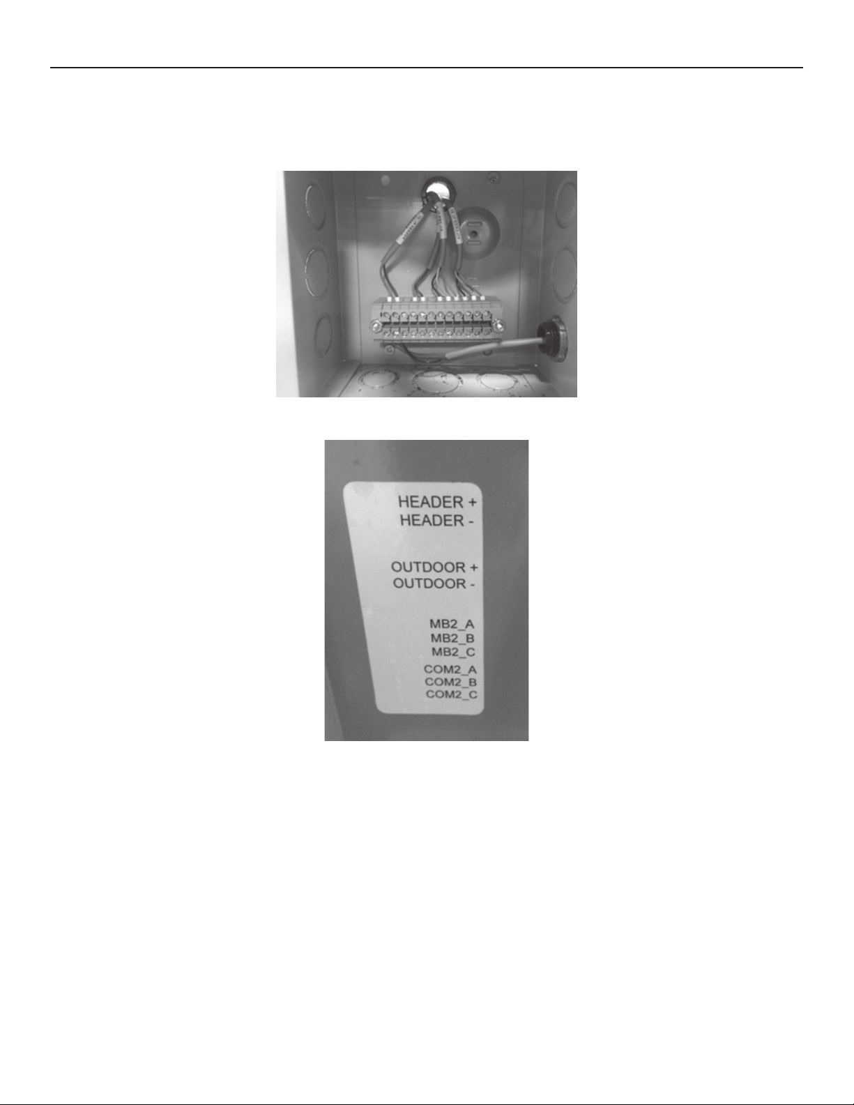
Open the door on the low voltage wiring box on the back side of the heater to see the terminal strip where to connect the gateway to the
boiler as shown in Figure 32
Figure 32. Boiler Terminal Strip
Inside the cover of the box shows the wiring legend for the terminal strip (see Figure 33).
Figure 33. Terminal Strip Wiring Legend
Place the Gateway on top of the heater or conveniently nearby.
Locate a knock out on the right side of the low voltage box to run the communication cable through to the inside of the low voltage box.
The boiler does not have an RJ-45 connector as do the water heaters to connect Port A of the gateway, so the plug on the other end of
the communications cable must also be cut off with a wire cutter. Locate and strip the insulation ½ inch from the brown, brown/white
and blue/white wires. Connect the brown/white wire to COM2_A, the brown wire to COM2_B, and the blue/white wire to COM2_C.
12
Page 13
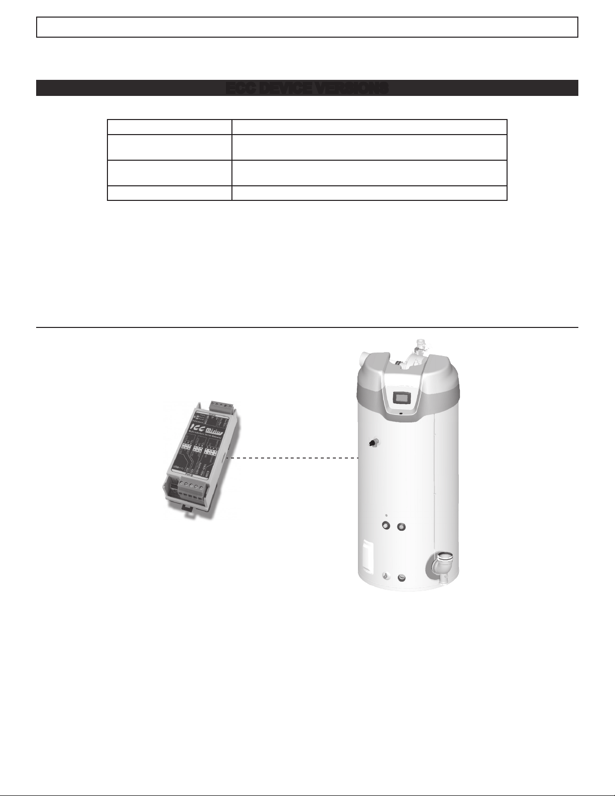
Two versions of the ECC are available as follows:
BACnet / Gas Water Heaters
ECC DEVICE VERSIONS
Product:
Product Model Number:
Product Version:
BACnet Protocol Revision:
The following sections describe the ECC communications characteristics available with each of the following types of water heaters:
• BACnet/Gas
• BACnet/Electric
• BACnet/Boilers
• ModBus/Gas
• ModBus/Electric
ICC Gateway (for use with XiTM and MXiTM Gas Water Heaters)
• 100316044 (Mirius for BACnet MT/TP)
• 100316045 (ETH-1000 for BACnet IP)
V3.000 (Mirius) or
V4.001 or greater (ETH-1000)
12 (135-2010)
BACNET / GAS WATER HEATERS
Figure 34. Cyclone Xi Gas Water Heaters (Virtual BACnet device via ICC Gateway)
PRODUCT DESCRIPTION
The Mirius is a multiprotocol RS-485 to RS-485 gateway. The ETH-1000 is an Ethernet to RS-485 multiprotocol gateway. These
products supports native BACnet, connecting directly to IP or the MS/TP LAN using baud rates of 4800, 9600, 19200, 38400, 57600,
76800, and 115200. As shipped the devices are congured as a BACnet Server.
All XI™ MXi™ controls provide communications via propriety protocol with the ICC Gateway. The Mirius supports BACnet MS/TP
communications and the ETH-1000 supports BACnet/IP to access data available at the display plus control of a limited number of
points such as Operating Setpoint.
13
Page 14

BACnet / Gas Water Heaters
PROTOCOL IMPLEMENTATION CONFORMANCE STATEMENT (PICS)
BACnet Standardized Device Prole (Annex L):
BACnet Application Specic Controller (B-ASC)
BACnet Interoperability
Table 3. BACnet Interoperability Building Blocks Supported (Annex K):
Data Sharing - ReadProperty-A (DS-RP-A)
Data Sharing - ReadProperty-B (DS-RP-B)
Data Sharing - ReadPropertyMultiple-B (DS-RPM-B)
Data Sharing - WriteProperty-A (DS-WP-A)
Data Sharing - WriteProperty-B (DS-WP-B)
Data Sharing - WritePropertyMultiple-B (DS-WPM-B)
Data Sharing – COV-B (DS-COV-B) (BACnet/IP only)
Device Management-Dynamic Device Binding-A (DM-DDB-A)
Device Management-Dynamic Device Binding-B (DM-DDB-B)
Device Management-Dynamic Object Binding-B (DM-DOB-B)
Device Management-Device Communication Control-B (DM-DCC-B)
Device Management – ReinitializeDevice-B (DM-RD-B)
Segmentation Capability
Segmentation not supported.
Data Link Layer Options
Table 4. Data Link Layer Options
BACnet IP (Annex J) (ETH-1000 only)
BACnet IP (Annex J), Foreign Device (ETH-1000 only)
ANSI/ATA 878.1, 2.5Mb. ARCNET (Clause 8)
ANSI/ATA 878.1, RS-485. ARCNET (Clause 8), baud rates() ________
MS/TP master (Clause9) baud rate(s): 4800, 19200, 38400, 57600,
76800, 115200
MS/TP slave (Clause9) baud rate(s): _________
Point-To-Point, EIA 232 (Clause 10), baud rate(s): _________
Point-To-Point, modem (Clause 10), baud rate(s): _________
LonTalk, (Clause 11), medium ________
Other: _________________
Device Address Binding
Is static device binding supported? (This is currently for two-way communications with MS/TP slaves and certain other devices.) YES
14
Page 15

Networking Options
Character Sets
BACnet / Gas Water Heaters
Table 5. Networking Options
Router, Clause 6 – List all routing congurations
Annex H, BACnet Tunneling Router over IP
BACnet/IP Broadcast Management Device (BBMD). Does the BBMD
support registrations by Foreign Devices? (ETH-1000 only)
Table 6. Character Sets Supported
ANSI X3.4
IBMTM /MicrosoftTM DBCS
ISO 8859-1
ISO 10646 (UCS-2)
ISO 10646 (UCS-4)
JIS C 6226
Data Types
The following table summarizes the data types that are accepted (in the case of a write property service) and returned (in the case of a
read property service) when targeting the present value property of each supported object type.
Table 7. Data Types Supported
Service
Object Type
Analog Output
Read Property Write Property
Real Real, Unsigned, Integer, Null
Analog Value
Analog Input Real N/A
Binary Output
Enumerated Enumerated, Boolean, Real, Unsigned, Integer, Null
Binary Value
Binary Input Enumerated N/A
Multi-state Output
Unsigned Real, Enumerated, Unsigned, Integer, Null
Multi-state Value
Multi-state Input Unsigned N/A
15
Page 16

Object Types and Properties
Property Device
Object Identier
Object Name
Object Type
System Status
Vendor Name
Vendor Identier
Model Name
Firmware Revision
App S/W Revision
Protocol Revision
Services Supported
Object Types Supported
Object List
Max APDU Length
Segmentation Support
APDU Timeout
Number APDU Retries
Max master
Max Info Frames
Device Address Binding
Database Revision
Present Value
Status Flags
Event State
Out-of Service
Units
Priority Array
Relinquish Default
Polarity
Inactive Text
Active Text
R - readable using BACnet services
W - readable and writable using BACnet services
BACnet / Gas Water Heaters
Table 8. Object Types/Property Support Table
Binary
Input
R R R R R R R R R R
R R R R R R R R R R
R R R R R R R R R R
R
R
R
R
R
R
R
R
R
R
R
R
R
R
R
R
R
R
R W W R W W R W W
R R R R R R R R R
R R R R R R R R R
R R R R R R R R R
R R R R R R
R R R R R
R R R R R
R R
R R
R R
Binary
Output
Binary
Value
Analog
Input
Analog
Output
Analog
Value
Multi
Input
Multi
Output
Multi
Value
DEVICE OBJECT LISTINGS
Object Min/Max Values
Note: Point listings have been changed completely from earlier versions of this listing.
Table 9. Device Object
Property Name ID BACnet Data Type RW Initial Value
(Mirius)
Initial Value
(ETH-1000)
Object_Identier 75 Object Identier RW Device, 520081 Device, 520081
Object_Name 77 Character String RW Water Heater-01 Water Heater-01
Object_Type 79 Enumerated R Device Device
System_Status 112 R Operational Operational
16
Page 17

BACnet / Gas Water Heaters
Table 9. Device Object
Property Name ID BACnet Data Type RW Initial Value
(Mirius)
Vendor_Name 121 R ICC, Inc. ICC, Inc.
Vendor_Identier 120 R 242 242
Model_Name 70 R Mirius ETH-1000
Firmware_Revision 44 Character String R V3.300 V4.002
Application_Software_Version 12 R V3.300 V4.002
Protocol_Version 98 R 1
Protocol_Revision 139 R 2
Protocol_Services_Supported 97 R See PICS
Protocol_Object_Types_Supported 96 R AI, AO, AV, BI,
BO, BV, MSI,
MSO, MSV
Object_List 76 R See Table See Table
Max_APDU_Length_Accepted 62 R 480 1444
Segmentation_Supported 107 R 3 3
APDU_Timeout 10 RW 1000ms 1000ms
Number_Of_APDU_Retries 73 R 3 3
Max_Master 64 RW 127 Unsupported
Device_Address_Binding 30 R {} {}
Local_Date 56 R Unsupported Unsupported
Local_Time 57 R Unsupported Unsupported
Initial Value
(ETH-1000)
AI, AO, AV, BI,
BO, BV, MSI,
MSO, MSV
BACnet/Gas Water Heaters Object List
• Not all models support all registers. Also parameter names may be different than shown here on some models.
• This table may be subject to change in the future.
• Adjustable objects are in bold and indicated by “W” (writable).
Table 10. BACnet/Gas Water Heaters Object List
BACnet
Object Name
(Description)
Firmware Ver-Rev
(Firmware Version)
Conguration Analog Input 2 Present_Value R
Upper Temperature
(Upper or Primary Temperature)
Lower Temperature
(Lower or Secondary Temperature)
Tank Temperature
(Controlling Tank Temperature algorithmically
calculated)
Temper Setpoint
(Desired Tank Temperature)
SetPoint Differ
(Setpoint Differential)
1. Data is encoded into the 16 bits as major revision (upper 8 bits) and minor revision (lower 8 bits).
2. Not recommended for use currently as UIM does not currently support and warning will come up as “Unknown.”
1
BACnet
Object
Type/Inst.
Analog Input 1 Present_Value R
Analog Input 3 Present_Value R ºC
Analog Input 4 Present_Value R ºC
Analog Input 5 Present_Value R ºC
Analog Value 201 Present_Value R/W ºC
Analog Value 202 Present_Value R/W °C
BACnet
Object
Property R/W Units
(ºF)
(°F)
Min
Value
(if W)
32.2
(90)
1.1
(2)
Max
Value
(if W) Xi 1.0 Mxi
82.2
(180)
11.1
(20)
17
Page 18

BACnet / Gas Water Heaters
Table 10. BACnet/Gas Water Heaters Object List
BACnet
Object Name
(Description)
Mxi Mod% Cmd
Commands Modulation % (0%=minimum heat,
100%=rated heat). Note: It is really an upper limit.
If heater wants to command less it will.
MxiLowTempAlrmSP2
(Low Temperature Alarm)
Number of Cycles
(Number of heating cycles)
Elapsed Time
(Time heater has been powered up in Hours with
two place beyond the decimal)
Elapsed Days
(The number of days that the heater has been
powered up)
Elapsed Hours
(The hours portion that the heater has been powered up. Use with Elapsed Days)
Heating Time
(Time heater has been actually heating water in
Hours with two place beyond the decimal)
Heating Days
(The amount of time in number of days heater has
been actually heating water)
Heating Hours
(The hours portion of the amount of time heater
has been actually heating water. Use with Heating
Days)
IgniterCurrent
(Hot Surface Igniter current in amps)
#CCB HW Faults
(CCB Hardware Fault Counter)
#Model Faults
(Model Fault Counter)
#Upper Temp Faults
(Upper Temperature Probe Fault Counter)
#Lower Temp Faults
(Lower Temperature Probe Fault Counter)
#Flame Probe Flt
(Flame Probe Fault Counter)
#Flame Status Flt
(Flame detect or not detected at proper time Fault
Counter)
#CCB Comm Faults
(Communication Fault Counter)
#ECO Faults
(High temperature Energy Cut Off switch in Upper
temperature probe Fault Counter)
#LowGasPress Flt
(Low Gas Pressure switch Fault Counter)
#Blocked In Flts
(Blocked Inlet pressure switch Fault Counter)
#Blocked Exhst Flt
(Blocked Exhaust Pressure & Condensate switch
Fault Counter)
#Ext Vent Faults
(External Vent Fault Counter)
#Blower Prv Flts
(Blower Prove Pressure Switch Fault Counter)
#Igniter Faults
(Igniter Fault Counter)
1. Data is encoded into the 16 bits as major revision (upper 8 bits) and minor revision (lower 8 bits).
2. Not recommended for use currently as UIM does not currently support and warning will come up as “Unknown.”
BACnet
Object
Type/Inst.
Analog Value 207 Present_Value R/W % 0 100
Analog Value 208 Present_Value R/W ºC
Analog Value 209 Present_Value R
Analog Value 210 Present_Value R Hours with two
Analog Value 211 Present_Value R Days
Analog Value 212 Present_Value R Hours
Analog Value 213 Present_Value R Hours with two
Analog Value 214 Present_Value R Days
Analog Value 215 Present_Value R Hours
Analog Value 216 Present_Value R Amps
Analog Value 217 Present_Value R
Analog Value 218 Present_Value R
Analog Value 219 Present_Value R
Analog Value 220 Present_Value R
Analog Value 221 Present_Value R
Analog Value 222 Present_Value R
Analog Value 223 Present_Value R
Analog Value 224 Present_Value R
Analog Value 225 Present_Value R
Analog Value 226 Present_Value R
Analog Value 227 Present_Value R
Analog Value 228 Present_Value R
Analog Value 229 Present_Value R
Analog Value 230 Present_Value R
BACnet
Object
Property R/W Units
(ºF)
places beyond
the decimal.
places beyond
the decimal.
Min
Value
(if W)
32.2
(90)
Max
Value
(if W) Xi 1.0 Mxi
82.2
(180)
18
Page 19

BACnet / Gas Water Heaters
Table 10. BACnet/Gas Water Heaters Object List
BACnet
Object Name
(Description)
#Ignition Failure
(Ignition Failure Fault Counter)
#Powr Supply Flt
(Power Supply Fault Counter)
#Powr Anode Flts
(Powered Anode Alert Counter)
EMS Mode-Status Analog Value 263 Present_Value R/W Xi 1.0 see table 3
BACnet
Object
Type/Inst.
Analog Value 231 Present_Value R
Analog Value 232 Present_Value R
Analog Value 233 Present_Value R
BACnet
Object
Property R/W Units
Min
Value
(if W)
Max
Value
(if W) Xi 1.0 Mxi
Upper Temp Open
(Upper temperature Probe open status)
Upper Temp Short
(Upper temperature Probe shorted status)
MXi Call For Heat Binary Input 303 Present_Value R 0 = No
Lower Temp Open
(Upper temperature Probe open status)
Lower Temp Short
(Upper temperature Probe shorted status)
Igntr Current OK
(Igniter Current Sensed)
Flame Sensed
(Igniter Current Sensed)
Blower Prove PS
(Blower Prove pressure switch)
Ext Vent PS
(External Vent pressure switch status if selected by
DIP switch on CCB)
Blocked Exhaust PS
(Blocked exhaust pressure switch)
Blocked Inlet PS
(Blocked air intake pressure switch)
Low Gas PS
(Low Gas supply pressure switch)
Upper Temp ECO
(Upper temperature probe high temperature Energy Cut Out Status)
External T’stat
(External Thermostat status if selected by DIP
switch on CCB)
Xi 1.0 Call For Heat
(Conditions are satised to allow heater to heat
water)
MXi LowTemp Alrm
(Tank temperature below Low Tank Temperature
Alarm setpoint)
MXi LeakDetected
(Optional Leak detector circuit detected water)
Mxi HeaterEnab’d
(Front Switch Heater Enable status)
MXi External Enab
(Optional input status)
Xi 1.0 Ign Tries
(Number of tries for ignition set by DIP switch on
CCB)
Ext Vent Relay
(External Vent Relay output commanded status)
1. Data is encoded into the 16 bits as major revision (upper 8 bits) and minor revision (lower 8 bits).
2. Not recommended for use currently as UIM does not currently support and warning will come up as “Unknown.”
Binary Input 301 Present_Value R 0 = Okay
1 = Open
Binary Input 302 Present_Value R 0 = Okay
1 = Shorted
1 = Yes
Binary Input 304 Present_Value R 0 = Okay
1 = Open
Binary Input 305 Present_Value R 0 = Okay
1 = Shorted
Binary Input 306 Present_Value R 0=No Current
1=Current
Sensed
Binary Input 307 Present_Value R 0=No Flame
1=Flame Sensed
Binary Input 308 Present_Value R 0=Open Switch
1=Closed Switch
Binary Input 309 Present_Value R 0=Open Switch
1=Closed Switch
Binary Input 310 Present_Value R 0=Open Switch
1=Closed Switch
Binary Input 311 Present_Value R 0=Open Switch
1=Closed Switch
Binary Input 312 Present_Value 0=Open Switch
1=Closed Switch
Binary Input 313 Present_Value 0=Open Switch
1=Closed Switch
Binary Input 314 Present_Value 0 = No
1 = Yes
Binary Input 315 Present_Value 0 = Okay
1 = Alarm
Binary Input 316 Present_Value 0 = Okay
1 = Alarm
Binary Input 317 Present_Value 0=No Leak
1=Leak Detected
Binary Input 318 Present_Value 0=Disabled
1 = Enabled
Binary Input 319 Present_Value 0=Disabled
1 = Enabled
Binary Input 320 Present_Value 0 = 3 tries
1 = 1 try
Binary Output 401 Present_Value 0 = Off
1 = On
19
Page 20

BACnet / Gas Water Heaters
Table 10. BACnet/Gas Water Heaters Object List
BACnet
Object Name
(Description)
Blower Relay
(Blower Relay output commanded status)
Ignition Relay
(Ignition Relay output commanded status)
Gas Valve Relay
(Gas valve Relay output commanded status)
MXi Ign Tries
(Selects 1 or 3 tries for ignition. Settable at UIM)
MXi Use Ext Enab
(Selects whether or not to use Optional External
Enable Input. Settable at UIM)
MXi Modulation
(CCB S/W version 3.15 or higher. Disables mod-
ulation on heaters that have it. May be helpful if
plumbed with Xi 1.0. Settable at UIM)
System In Fault Binary Value 504 Present_Value 0 = Okay
System State
(CCB Control State)
Fault Code Multistate Value 802 Present_Value
Alert Code Multistate Value 803 Present_Value
1. Data is encoded into the 16 bits as major revision (upper 8 bits) and minor revision (lower 8 bits).
2. Not recommended for use currently as UIM does not currently support and warning will come up as “Unknown.”
BACnet
Object
Type/Inst.
Binary Output 402 Present_Value 0 = Off
Binary Output 403 Present_Value 0 = Off
Binary Output 404 Present_Value 0 = Off
Binary Value 501 Present_Value 0 = 3 tries
Binary Value 502 Present_Value 0 = No
Binary Value 503 Present_Value 0=Disabled
Multistate Value 801 Present_Value
BACnet
Object
Property R/W Units
1 = On
1 = On
1 = On
1 = 1 try
1 = Yes
1=Enabled
1 = Alarm
See Table 10
See Table 13
See Table 13
Min
Value
(if W)
Max
Value
(if W) Xi 1.0 Mxi
Central Control Board Major State Denitions
Table 11. Gas Central Control Board (CCB) Major State Denitions
Value Xi 1.0 State MXi State
1 Off (Standby) Off (Standby)
2 Pre-Purge Pre-Purge
3 Igniter Warmup Igniting
4 Ignition Activation Gas Valve On
5 Ignition Verication Inter-Purge
6 Inter-Purge Heating
7 Heating Post-Purge
8 Post-Purge In Fault
9 Fault
Xi 1.0 Energy Management System (EMS) Control
Xi 1.0 uses a single bit setting method. Within the EMS Mode-Status point one bit command (bit 15) sets it in EMS mode, and other
ends EMS mode. Once in EMS mode, another bit command (bit 0) enables heating another disables heating.
Once in EMS mode the EMS Mode Refresh command must be periodically issued which clears a third bit (bit 14) to maintain EMS
mode, otherwise the heater will end EMS mode and resume normal operation.
20
Page 21

BACnet / Gas Water Heaters
Table 12. Xi 1.0 Energy Management System (EMS) Control
Decimal Hex Value Response
3840 0x0F00 No EMS control 0 / 0x000
3841 0x0F01 Put into EMS Mode^ 49152 / 0xC000
0000 0x0000 EMS Disable heating^ 49152 / 0xC000
0001 0x0001 EMS Enable heating^ 49153 / 0xC001
3584 0x0E00 EMS Mode Refresh^ (must write within 30 seconds
or EMS mode ends.) 15 seconds or less
recommended
Notes:
The start of a heating also depend on other factors like tank temperature dropping below Setpoint – Differential and External T’stat call for heat if that option is enabled.
Depending on when you poll the register, you may read bit 14 as 1 which is why a “C” (in hexadecimal form) might briefly reply with “8”. This is due to the control setting
this bit and if it not cleared periodically by the BACnet command, heating is disabled.
After disabling EMS mode with write of 3840, read back might have bits 14 and 1 possibly still set. To make sure these bits are clear, write a 0000 to clear bit 1 and 3584 to
clear bit 14.
Mxi Energy Management System (EMS) Control
Mxi EMS control is written as a single command to place in EMS mode and enable or disable heating.
Once in EMS mode the EMS Mode Refresh command must be periodically issued to maintain EMS mode, otherwise the heater will end
EMS mode and resume normal operation.
49152 / 0xC000 or 49153 / 0xC001 depending on
whether or not heating is enabled.
Table 13. Mxi Energy Management System (EMS) Control
Decimal Hex Value Response
0 0x0000 No EMS control~ 0 / 0x000
32768 0x8000 EMS Disable Heating^ 49152 / 0xC000
32769 0x8001 EMS Enable Heating^* 49153 / 0xC001
Notes:
~ For Versions less than 3.16, once EMS control mode is enabled it remains enabled through BACnet it will remain in EMS control mode that cannot be cleared by writing
a 0 to it. Power cycling only can clear EMS mode.
^ Depending on when you poll the register, you may read bit 14 as 1 which is why a “C” (in hexadecimal form) might briefly reply with “8”. This is due to the control setting
this bit and if it not cleared periodically by the BACnet command, heating is disabled.
* EMS command to heat must be sent every 30 maximum or heating will be disabled.
21
Page 22

BACnet / Gas Water Heaters
Fault Codes and Warnings
Note: Any Fault not listed is an internal CCB failure fault.
Table 14. Fault codes and Warnings
Index Range
(Decimal)
1 1 Okay (No Fault)
1 6 Memory
24 Incorrect Model
51 56 Power Monitor
69 72 Temperature Probe Open or Short
129 129 Leak Detected
153 154 Communications Fault
165 High temperature ECO (Energy Cut Off)
175 Safety Relay Closed fault
176 188 CCB internal errors
193 194 Processor Clock
198 201 Non-volatile Memory
204 217 Powered Anode
431 Safety Relay Opened fault
Value
22
Page 23

BACNET / ELECTRIC WATER HEATERS
BACnet / Electric Water Heaters
Figure 35. Custom and Gold Xi™ Series Electric Water Heaters (Virtual BACnet device via ICC Gateway)
PRODUCT DESCRIPTION
The Mirius is a multiprotocol RS-485 to RS-485 gateway. The ETH-1000 is an Ethernet to RS-485 multiprotocol gateway. These
products supports native BACnet, connecting directly to IP or the MS/TP LAN using baud rates of 4800, 9600, 19200, 38400, 57600,
76800, and 115200. As shipped the devices are congured as a BACnet Server.
All electronic controls provide communications via propriety protocol with the ICC Gateway. The Mirius supports BACnet MS/TP
communications and the ETH-1000 supports BACnet IP to access data available at the display plus control of a limited number of
points such as Operating Setpoint.
PROTOCOL IMPLEMENTATION CONFORMANCE STATEMENT (PICS)
BACnet Standardized Device Prole (Annex L):
BACnet Application Specic Controller (B-ASC)
BACnet Interoperability
Table 15. BACnet Interoperability Building Blocks Supported (Annex K):
Data Sharing - ReadProperty-A (DS-RP-A)
Data Sharing - ReadProperty-B (DS-RP-B)
Data Sharing - ReadPropertyMultiple-B (DS-RPM-B)
Data Sharing - WriteProperty-A (DS-WP-A)
Data Sharing - WriteProperty-B (DS-WP-B)
Data Sharing - WritePropertyMultiple-B (DS-WPM-B)
Data Sharing – COV-B (DS-COV-B) (BACnet/IP only)
Device Management-Dynamic Device Binding-A (DM-DDB-A)
Device Management-Dynamic Device Binding-B (DM-DDB-B)
Device Management-Dynamic Object Binding-B (DM-DOB-B)
23
Page 24

Device Management-Device Communication Control-B (DM-DCC-B)
Device Management – ReinitializeDevice-B (DM-RD-B)
Segmentation Capability
Segmentation not supported.
Data Link Layer Options
BACnet IP (Annex J) (ETH-1000 only)
BACnet IP (Annex J), Foreign Device (ETH-1000 only)
ANSI/ATA 878.1, 2.5Mb. ARCNET (Clause 8)
ANSI/ATA 878.1, RS-485. ARCNET (Clause 8), baud rates() ________
MS/TP master (Clause9) baud rate(s): 4800, 19200, 38400, 57600, 76800, 115200
MS/TP slave (Clause9) baud rate(s): _________
Point-To-Point, EIA 232 (Clause 10), baud rate(s): _________
Point-To-Point, modem (Clause 10), baud rate(s): _________
LonTalk, (Clause 11), medium ________
Other: _________________
BACnet / Electric Water Heaters
Table 15. BACnet Interoperability Building Blocks Supported (Annex K):
Table 16. Data Link Layer Options
Device Address Binding
Is static device binding supported? (This is currently for two-way communications with MS/TP slaves and certain other devices.) YES
Networking Options
Table 17. Networking Options
Router, Clause 6 – List all routing congurations
Annex H, BACnet Tunneling Router over IP
BACnet/IP Broadcast Management Device (BBMD). Does the BBMD support registrations by
Foreign Devices? (ETH-1000 only)
Character Sets
Table 18. Character Sets Supported
ANSI X3.4
IBMTM /MicrosoftTM DBCS
ISO 8859-1
ISO 10646 (UCS-2)
ISO 10646 (UCS-4)
JIS C 6226
24
Page 25

Data Types
Object Type
Analog Output
Analog Value
Analog Input Real N/A
Binary Output
Binary Value
Binary Input Enumerated N/A
Multi-state Output
Multi-state Value
Multi-state Input Unsigned N/A
Object Types and Property Support
Property Device
Object Identier
Object Name
Object Type
System Status
Vendor Name
Vendor Identier
Model Name
Firmware Revision
App S/W Revision
Protocol Revision
Services Supported
Object Types Supported
Object List
Max APDU Length
Segmentation Support
APDU Timeout
Number APDU Retries
Max master
Max Info Frames
Device Address Binding
Database Revision
Present Value
Status Flags
Event State
Out-of Service
Units
Priority Array
Relinquish Default
Polarity
R - readable using BACnet services
W - readable and writable using BACnet services
BACnet / Electric Water Heaters
Table 19. Data Types Supported
Service
Read Property Write Property
Real Real, Unsigned, Integer, Null
Enumerated Enumerated, Boolean, Real, Unsigned, Integer, Null
Unsigned Real, Enumerated, Unsigned, Integer, Null
Table 20. Object Types/Property Support Table
Binary
Input
R R R R R R R R R R
R R R R R R R R R R
R R R R R R R R R R
R
R
R
R
R
R
R
R
R
R
R
R
R
R
R
R
R
R
Binary
Output
Binary
Value
Analog
Input
Analog
Output
Analog
Value
Multi
Input
Multi
Output
Multi
Value
R W W R W W R W W
R R R R R R R R R
R R R R R R R R R
R R R R R R R R
R R R R R R
R R R R R
R R R R R
R R
25
Page 26

BACnet / Electric Water Heaters
Table 20. Object Types/Property Support Table
Binary
Property Device
Input
Inactive Text
Active Text
R - readable using BACnet services
W - readable and writable using BACnet services
DEVICE OBJECT LISTINGS
Device Objects Initial Values
Table 21. BACnet/Electric Water Heaters Device Object
Property Name ID BACnet Data Type RW Initial Value
Object_Identier 75 Object Identier RW Device, 520081 Device, 520081
Object_Name 77 Character String RW Elec Water Heater Elec Water Heater
Object_Type 79 Enumerated R Device Device
System_Status 112 R Operational Operational
Vendor_Name 121 R ICC, Inc.
Vendor_Identier 120 R 242
Model_Name 70 R Mirius ETH-1000
Firmware_Revision 44 Character String R V3.000 V4.001
Application_Software_Version
Protocol_Version 98 R 1 1
Protocol_Revision 139 R 12 12
Protocol_Services_Supported 97 R See PICS See PICS
Protocol_Object_Types_Supported 96 R AI, AO, AV, BI, BO, BV,
Object_List 76 R See Table See Table
Max_APDU_Length_Accepted 62 R 480 1444
Segmentation_Supported 107 R 3 3
APDU_Timeout 10 RW 1000ms 1000ms
Number_Of_APDU_Retries 73 R 3 3
Max_Master 64 RW 127 Unsupported
Device_Address_Binding 30 R {} {}
Local_Date 56 R Unsupported Unsupported
Local_Time 57 R Unsupported Unsupported
12 R
Binary
Output
R R
R R
Binary
Value
Analog
Input
Analog
Output
Analog
Value
Multi
Input
Multi
Output
Initial Value
(Mirius)
V3.000 V4.001
MSI, MSO, MSV
AI, AO, AV, BI, BO, BV,
MSI, MSO, MSV
Multi
Value
(ETH-1000)
Device Objects Minimum/Maximum Values
• Not all models support all registers. Also parameter names may be different than shown here on some models.
• This table may be subject to change in the future.
• Adjustable objects are in bold and indicated by “W” (writable).
• Mirius Object names may be abbreviated to t in 16 characters.
• Where noted, some objects implemented only in ETH-1000.
Table 22. BACnet/Electric Water Heaters Object List
BACnet
Object Name
(Description)
Firmware Ver-Rev1
(Firmware Version)
Conguration Analog Input 2 Present_Value R
1. Data is encoded into the 16 bits as major revision (upper 8 bits) and minor revision (lower 8 bits).
BACnet
Object
Type/Inst.
Analog Input 1 Present_Value R
BACnet
Object
Property R/W Units
26
Min
Value
(if W)
Max
Value
(if W)
Page 27

BACnet / Electric Water Heaters
Table 22. BACnet/Electric Water Heaters Object List
BACnet
Object Name
(Description)
Tank Temperature
(Controlling (Tank) Temperature)
Lower Temperature
(Lower or Secondary Temperature)
Tank Temperature
(Controlling Tank Temperature algorithmically
calculated)
Temper Setpoint
(Desired Tank Temperature)
Differen’lBank1
(Differential Setpoint Bank 1)
Differen’lBank2
(Differential Setpoint Bank 2)
Differen’lBank3
(Differential Setpoint Bank 3)
Differen’lBank4
(Differential Setpoint Bank 4)
Differen’lBank5
(Differential Setpoint Bank 5)
Number of Cycles
(Number of heating cycles)
Elapsed Time
(Time heater has been powered up in Hours
with two place beyond the decimal)
Elapsed Days
(The number of days that the heater has been
powered up)
Elapsed Hours
(The hours portion that the heater has been
powered up. Use with Elapsed Days)
Heating Time
(Time heater has been actually heating water
in Hours with two place beyond the decimal)
Heating Days
(The amount of time in number of days heater
has been actually heating water)
Heating Hours
(The hour’s portion of the amount of time
heater has been actually heating water. Use
with Heating Days)
#CCB HW Faults
(CCB Hardware Fault Counter)
#Model Faults
ETH-1000 ONLY
(Model Fault Counter)
#Temp Probe Faults
(Temperature Probe Fault Counter)
#CCB Comm Faults
ETH-1000 only
(Communication Fault Counter)
#ECO Faults
(High temperature Energy Cut Off switch in
Upper temperature probe Fault Counter)
#Powr Anode Flts
(Powered Anode Alert Counter)
#Element Faults
(Element Fault Counter)
#LWCO Faults
(Low Water Cut Off Fault Counter)
#Element Banks Used
(Number of Element Banks in Water Heater)
1. Data is encoded into the 16 bits as major revision (upper 8 bits) and minor revision (lower 8 bits).
BACnet
Object
Type/Inst.
Analog Input 5 Present_Value R ºC
Analog Input 4 Present_Value R ºC
Analog Input 5 Present_Value R ºC
Analog Value 201 Present_Value R/W ºC
Analog Value 202 Present_Value R/W °C
Analog Value 203 Present_Value R/W °C
Analog Value 204 Present_Value R/W °C
Analog Value 205 Present_Value R/W °C
Analog Value 206 Present_Value R/W °C
Analog Value 209 Present_Value R Number
Analog Value 210 Present_Value R Hours with two
Analog Value 211 Present_Value R Days
Analog Value 212 Present_Value R Hours
Analog Value 213 Present_Value R Hours with two
Analog Value 214 Present_Value R Days
Analog Value 215 R R Hours
Analog Value 217 Present_Value R Number
Analog Value 218 Present_Value R Number
Analog Value 219 Present_Value R Number
Analog Value 223 Present_Value R Number
Analog Value 224 Present_Value R Number
Analog Value 233 Present_Value R Number
Analog Value 234 Present_Value R Number
Analog Value 235 Present_Value R Number
Analog Value 236 Present_Value R Number
BACnet
Object
Property R/W Units
places beyond the
decimal.
places beyond the
decimal.
(ºF)
(°F)
(°F)
(°F)
(°F)
(°F)
Min
Value
(if W)
32.2
(90)
.6
(1)
.6
(1)
.6
(1)
.6
(1)
.6
(1)
Max
Value
(if W)
82.2
(180)
11.1
(20)
11.1
(20)
11.1
(20)
11.1
(20)
11.1
(20)
27
Page 28

BACnet / Electric Water Heaters
Table 22. BACnet/Electric Water Heaters Object List
BACnet
Object Name
(Description)
#Elements in Bank 1
(Number elements current is check for in bank
1)
#Elements in Bank 2
(Number elements current is check for in bank
2)
#Elements in Bank 3
(Number elements current is check for in bank
3)
#Elements in Bank 4
(Number elements current is check for in bank
4)
#Elements in Bank 5
(Number elements current is check for in bank
5)
#Banks Cmd’d On
(Number of Banks currently Commanded to
be on)
Bank On Time
ETH-1000 only
(Time bank has been powered up in Hours
with two place beyond the decimal)
Bank1 On Days
(The amount of time in number of days bank
has been actually heating water)
Bank1 On Hours
(The hour’s portion of the amount of time bank
has been actually heating water. Use with
Bank1 On Days)
Bank2 On Time
ETH-1000 only
(Time bank has been powered up in Hours
with two place beyond the decimal)
Bank2 On Days
(The amount of time in number of days bank
has been actually heating water)
Bank2 On Hours
(The hour’s portion of the amount of time bank
has been actually heating water. Use with
Bank2 On Days)
Bank3 On Time
ETH-1000 only
(Time bank has been powered up in Hours
with two place beyond the decimal)
Bank3 On Days
(The amount of time in number of days bank
has been actually heating water)
Bank3 On Hours
(The hour’s portion of the amount of time bank
has been actually heating water. Use with
Bank3 On Days)
Bank4 On Time
ETH-1000 only
(Time bank has been powered up in Hours
with two place beyond the decimal)
Bank4 On Days
(The amount of time in number of days bank
has been actually heating water)
Bank4 On Hours
(The hour’s portion of the amount of time bank
has been actually heating water. Use with
Bank4 On Days)
1. Data is encoded into the 16 bits as major revision (upper 8 bits) and minor revision (lower 8 bits).
BACnet
Object
Type/Inst.
Analog Value 237 Present_Value R Number
Analog Value 238 Present_Value R Number
Analog Value 239 Present_Value R Number
Analog Value 240 Present_Value R Number
Analog Value 241 Present_Value R Number
Analog Value 242 Present_Value R Number
Analog Value 243 Present_Value R Hours with two
Analog Value 244 Present_Value R Days
Analog Value 245 Present_Value R Hours
Analog Value 246 Present_Value R Hours with two
Analog Value 247 Present_Value R Days
Analog Value 248 Present_Value R Hours
Analog Value 249 Present_Value R Hours with two
Analog Value 250 Present_Value R Days
Analog Value 251 Present_Value R Hours
Analog Value 252 Present_Value R Hours with two
Analog Value 253 Present_Value R Days
Analog Value 254 Present_Value R Hours
BACnet
Object
Property R/W Units
places beyond the
decimal.
places beyond the
decimal.
places beyond the
decimal.
places beyond the
decimal.
Min
Value
(if W)
Max
Value
(if W)
28
Page 29

BACnet / Electric Water Heaters
Table 22. BACnet/Electric Water Heaters Object List
BACnet
Object Name
(Description)
Bank5 On Time
ETH-1000 only
(Time bank has been powered up in Hours
with two place beyond the decimal)
Bank5 On Days
(The amount of time in number of days bank
has been actually heating water)
Bank5 On Hours
(The hour’s portion of the amount of time bank
has been actually heating water. Use with
Bank5 On Days)
Bank 1 Heating Cycles Analog Value 258 Present_Value R Number
Bank 2 Heating Cycles Analog Value 259 Present_Value R Number
Bank 3 Heating Cycles Analog Value 260 Present_Value R Number
Bank 4 Heating Cycles Analog Value 261 Present_Value R Number
Bank 5 Heating Cycles Analog Value 262 Present_Value R Number
EMS Mode-Status Analog Value 263 Present_Value R/W see table 3
Element Status
(Each bit is state a separate element)
BACnet
Object
Type/Inst.
Analog Value 255 Present_Value R Hours with two
Analog Value 256 Present_Value R Days
Analog Value 257 Present_Value R Hours
Analog Value 264 Present_Value R Bit 0 = Element 1
BACnet
Object
Property R/W Units
places beyond the
decimal.
Bit 1 = Element 2
.
.
.
Bit 14 = Element
15
Min
Value
(if W)
Max
Value
(if W)
Temp Probe Open
(Temperature Probe open status)
Temp Probe Short
(Temperature Probe shorted status)
Temp Probe ECO Status
(Temperature probe high temperature Energy
Cut Out Status)
Safety Relay Feedback Binary Input 321 Present_Value R 0=Open
Tank Full (LWCO) Binary Input 322 Present_Value R 0=Open Switch
AC Input1 T’stat
(External Enable 1)
AC Input2 T’stat
(External Enable 2)
Bank1 Output Status Binary Output 405 Present_Value R 0=Off
Bank2 Output Status Binary Output 406 Present_Value R 0=Off
Bank3 Output Status Binary Output 407 Present_Value R 0=Off
Bank4 Output Status Binary Output 408 Present_Value R 0=Off
Bank5 Output Status Binary Output 409 Present_Value R 0=Off
Binary Input 301 Present_Value R 0 = Okay
1 = Open
Binary Input 302 Present_Value R 0 = Okay
1 = Shorted
Binary Input 313 Present_Value R 0=Open Switch
1=Closed Switch
1=Closed
1=Closed Switch
Binary Input 323 Present_Value R 0=Open
1=Closed
Binary Input 324 Present_Value R 0=Open
1=Closed
1=On
1=On
1=On
1=On
1=On
Alarm Condition Binary Value504 Present_Value R 0=False
1=True
Output Relay Status Binary Value 505 Present_Value R 0=Relay Off
1=Relay On
System In Fault Binary Value 504 Present_Value R 0 = Okay
1 = In Fault
1. Data is encoded into the 16 bits as major revision (upper 8 bits) and minor revision (lower 8 bits).
29
0 1
Page 30

BACnet / Electric Water Heaters
Table 22. BACnet/Electric Water Heaters Object List
BACnet
Object Name
(Description)
CCB System State
(Central Control Board Control State)
Fault Code Multistate Value 802 Present_Value R See Table 25
Alert Code Multistate Value 803 Present_Value R See Table 25
1. Data is encoded into the 16 bits as major revision (upper 8 bits) and minor revision (lower 8 bits).
Central Control Board Major State Denitions
Table 23. BACnet/Electric Water Heaters Central Control Board (CCB) State
Value State
0 Off (Standby)
6 Heating
8 Fault
Energy Management System (EMS) Control
Commercial Electric water heaters with Xi controls use a single bit setting method. Within the EMS Mode-Status point one bit
command (bit 15) sets it in EMS mode, and other ends EMS mode. Once in EMS mode, another bit command (bit 0) enables heating
another disables heating.
Once in EMS mode the EMS Mode Refresh command must be periodically issued which clears a third bit (bit 14) to maintain EMS
mode, otherwise the heater will end EMS mode and resume normal operation.
Table 24. BACnet/Electric Water Heaters Energy Management System (EMS) Control
Decimal Hex Value Response
3841 0x0F01 Put into EMS Mode^ 49152 / 0xC000
0000 0x0000 EMS Disable heating^ 49152 / 0xC000
0001 0x0001 EMS Enable heating^ 49153 / 0xC001
3584 0x0E00 EMS Mode Refresh^ (must
Notes:
BACnet
Object
Type/Inst.
Multistate Value 801 Present_Value R See Table 22
BACnet
Object
Property R/W Units
49152 / 0xC000 or 49153 /
write within 30 seconds or EMS
mode ends.) 15 seconds or
0xC001 depending on whether
or not heating is enabled.
less recommended
Min
Value
(if W)
Max
Value
(if W)
The start of a heating also depend on other factors like tank temperature dropping below Setpoint – Differential and External T’stat call
for heat if that option is enabled.
^Depending on when you poll the register, you may read bit 14 as 1 which is why a “C” (in hexadecimal form) might briefly reply with
“8”. This is due to the control setting this bit and if it not cleared periodically by the BACnet command, heating is disabled.
After disabling EMS mode with write of 3840, read back might have bits 14 and 1 possibly still set. To make sure these bits are clear,
write a 0000 to clear bit 1 and 3584 to clear bit 14.
Fault Codes and Warnings
Note: Any Fault not listed is an internal CCB failure fault.
Table 25. BACnet/Electric Water Heaters Fault codes and Warnings
Index Range
(Decimal) Value
1 1 Okay (No Fault) (If System In Fault =0 )
1 6 Memory (If System In Fault = 1)
24 Incorrect Model
30
Page 31

BACnet / Electric Water Heaters
Table 25. BACnet/Electric Water Heaters Fault codes and Warnings
Index Range
(Decimal) Value
51 56 Power Monitor
69 72 Temperature Probe Open or Short
153 154 Communications Fault
165 High temperature ECO (Energy Cut Off)
171 Low Water Cut-Off
175 Safety Relay Closed fault
176 188 CCB internal errors
193 194 Processor Clock
198 201 Non-volatile Memory
205 217 Powered Anode
431 Safety Relay Opened fault
1037 1037 Element Open Warning
31
Page 32

BACnet / Boilers
BACNET / BOILERS
Figure 36. XP XWH Circulating Water Heaters (Virtual Bacnet Device Via ICC Gateway)
PRODUCT DESCRIPTION
The Mirius is a multiprotocol RS-485 to RS-485 gateway. The ETH-1000 is an Ethernet to RS-485 multiprotocol gateway. These
products supports native BACnet, connecting directly to IP or the MS/TP LAN using baud rates of 4800, 9600, 19200, 38400, 57600,
76800, and 115200. As shipped the devices are congured as a BACnet Server.
All XITM MXiTM controls provide communications via propriety protocol with the ICC Gateway. The Mirius supports BACnet MS/TP
communications and the ETH- 1000 supports BACnet/IP to access data available at the display plus control of a limited number of
points such as Operating Setpoint.
PROTOCOL IMPLEMENTATION CONFORMANCE STATEMENT (PICS)
BACnet Standardized Device Prole (Annex L):
BACnet Application Specic Controller (B-ASC)
BACnet Boiler Interoperability
Table 26. BACnet Boiler Interoperability Building Blocks Supported (Annex K):
Data Sharing - ReadProperty-A (DS-RP-A)
Data Sharing - ReadProperty-B (DS-RP-B)
Data Sharing - ReadPropertyMultiple-B (DS-RPM-B)
Data Sharing - WriteProperty-A (DS-WP-A)
Data Sharing - WriteProperty-B (DS-WP-B)
Data Sharing - WritePropertyMultiple-B (DS-WPM-B)
Data Sharing – COV-B (DS-COV-B) (BACnet/IP only)
Device Management-Dynamic Device Binding-A (DM-DDB-A)
Device Management-Dynamic Device Binding-B (DM-DDB-B)
Device Management-Dynamic Object Binding-B (DM-DOB-B)
Device Management-Device Communication Control-B (DM-DCC-B)
Device Management – ReinitializeDevice-B (DM-RD-B)
Segmentation Capability:
Segmentation not supported
32
Page 33

BACnet / Boilers
Data Link Layer Options
Table 27. BACnet Boiler Data Link Layer Options
BACnet IP (Annex J) (ETH-1000 only)
BACnet IP (Annex J), Foreign Device (ETH-1000 only)
ANSI/ATA 878.1, 2.5Mb. ARCNET (Clause 8)
ANSI/ATA 878.1, RS-485. ARCNET (Clause 8), baud rates() ________
MS/TP master (Clause9) baud rate(s): 4800, 19200, 38400, 57600,
76800, 115200
MS/TP slave (Clause9) baud rate(s): _________
Point-To-Point, EIA 232 (Clause 10), baud rate(s): _________
Point-To-Point, modem (Clause 10), baud rate(s): _________
LonTalk, (Clause 11), medium ________
Other: _________________
Device Address Binding
Is static device binding supported? (This is currently for two-way communications with MS/TP slaves and certain other devices.) YES
Table 28. BACnet Boiler Networking Options
Router, Clause 6 – List all routing congurations
Annex H, BACnet Tunneling Router over IP
BACnet/IP Broadcast Management Device (BBMD). Does the BBMD
support registrations by Foreign Devices? (ETH-1000 only)
Character Sets
Table 29. BACnet Boiler Character Sets Supported
ANSI X3.4
IBMTM /MicrosoftTM DBCS
ISO 8859-1
ISO 10646 (UCS-2)
ISO 10646 (UCS-4)
JIS C 6226
Data Types Supported
The following table summarizes the data types that are accepted (in the case of a write property service) and returned (in the case of a
read property service) when targeting the present value property of each supported object type.
Table 30. BACnet Boiler Data Types Supported
Service
Object Type
Analog Output
Read Property Write Property
Real Real, Unsigned, Integer, Null
Analog Value
Analog Input Real N/A
Binary Output
Enumerated Enumerated, Boolean, Real, Unsigned, Integer, Null
Binary Value
Binary Input Enumerated N/A
Multi-state Output
Unsigned Real, Enumerated, Unsigned, Integer, Null
Multi-state Value
Multi-state Input Unsigned N/A
33
Page 34

Boiler Device Object Types/Property Support
Table 31. BACnet Boiler Object Types/Property Support Table
Binary
Property Device
Object Identier
Object Name
Object Type
System Status
Vendor Name
Vendor Identier
Model Name
Firmware Revision
App S/W Revision
Protocol Revision
Services Supported
Object Types Supported
Object List
Max APDU Length
Segmentation Support
APDU Timeout
Number APDU Retries
Max master
Max Info Frames
Device Address Binding
Database Revision
Present Value
Status Flags
Event State
Out-of Service
Units
Priority Array
Relinquish Default
Polarity
Inactive Text
Active Text
R - readable using BACnet services
W - readable and writable using BACnet services
R R R R R R R R R R
R R R R R R R R R R
R R R R R R R R R R
R
R
R
R
R
R
R
R
R
R
R
R
R
R
R
R
R
R
R R
R R
R R
Input
BACnet / Boilers
Binary
Output
R W W R W W R W W
R R R R R R R R R
R R R R R R R R R
R R R R R R R R R
R R R R R
R R R R R
Binary
Value
Analog
Input
Analog
Output
Analog
Value
Multi
Input
Multi
Output
R R R R R R
Multi
Value
OBJECT LISTINGS
Boiler Device Object Initial Values
Note: Point listings have been changed completely from earlier versions of this listing.
Table 32. BACnet/Boiler Device Object
Property Name ID BACnet Data Type RW Initial Value
(Mirius)
Initial Value
(ETH-1000)
Object_Identier 75 Object Identier RW Device, 520081 Device, 520081
Object_Name 77 Character String RW Water Heater-01 Water Heater-01
Object_Type 79 Enumerated R Device Device
34
Page 35

BACnet / Boilers
Table 32. BACnet/Boiler Device Object
Property Name ID BACnet Data Type RW Initial Value
(Mirius)
System_Status 112 R Operational Operational
Vendor_Name 121 R ICC, Inc. ICC, Inc.
Vendor_Identier 120 R 242 242
Model_Name 70 R Mirius ETH-1000
Firmware_Revision 44 Character String R V3.300 V4.002
Application_Software_Version 12 R V3.300 V4.002
Protocol_Version 98 R 1
Protocol_Revision 139 R 2
Protocol_Services_Supported 97 R See PICS
Protocol_Object_Types_Supported 96 R AI, AO, AV, BI,
BO, BV, MSI,
MSO, MSV
Object_List 76 R See Table See Table
Max_APDU_Length_Accepted 62 R 480 1444
Segmentation_Supported 107 R 3 3
APDU_Timeout 10 RW 1000ms 1000ms
Number_Of_APDU_Retries 73 R 3 3
Max_Master 64 RW 127 Unsupported
Device_Address_Binding 30 R {} {}
Local_Date 56 R Unsupported Unsupported
Local_Time 57 R Unsupported Unsupported
Initial Value
(ETH-1000)
AI, AO, AV, BI,
BO, BV, MSI,
MSO, MSV
Boiler Device Object Min/Max Values
• Not all models support all registers. Also parameter names may be different than shown here on some models.
• This table may be subject to change in the future.
• Adjustable objects are in bold and indicated by “W” (writable).
Table 33. BACnet/Boiler Object List
BACnet
Object Name
(Description)
Outlet Sensor Analog Input 1 Present_Value R ºC
Inlet Sensor Analog Input 2 Present_Value R ºC
Tank Sensor Analog Input 3 Present_Value R ºC
Burner 1 Rate % Analog Input 4 Present_Value R %
Burner 2 Rate % Analog Input 5 Present_Value R %
Burner 3 Rate % Analog Input 6 Present_Value R %
Burner 4 Rate % Analog Input 7 Present_Value R %
Master FireRate% Analog Input 8 Present_Value R %
Slave 1 State Analog Input 9 Present_Value R
Slave 2 State Analog Input 10 Present_Value R Number (See Table 34)
Slave 3 State Analog Input 11 Present_Value R Number (See Table 34)
Slave 4 State Analog Input 12 Present_Value R Number (See Table 34
Access Status
(Register Access Status)
Lockout Code
(Lockout i.e., fault and hold code)
BACnet
Object
Type/Inst.
Analog Input 13 Present_Value R Number (See Table 35)
Analog Input 14 Present_Value R Number (See Table 36)
BACnet
Object
Property R/W Units
Number (See Table 34)
Min
Value
(if W)
Max
Value
(if W)
35
Page 36

BACnet / Boilers
Table 33. BACnet/Boiler Object List
BACnet
Object Name
(Description)
Pump Run Time Analog Input 101 Present_Value R/W Seconds 0 64800
DHW P Gain
(Lead Lag P-gain)
DHW I Gain
(Lead Lag I-gain)
DHW D Gain
Lead Lag D-gain
BACnet
Object
Type/Inst.
Analog Input 102 Present_Value R Number 0 100
Analog Input 103 Present_Value R Number 0 100
Analog Input 104 Present_Value R Number 0 100
BACnet
Object
Property R/W Units
Min
Value
(if W)
Max
Value
(if W)
(18 hours)
Mode Sensor Sel
(Modulating Sensor Select /
DHW demand switch)
Lead Lag Set Pt
(Lead Lag DHW setpoint)
On Hysteresis
(Lead Lag on hysteresis)
Off Hysteresis
(Lead Lag on hysteresis)
DHW Hi Limit Set
(Outlet high limit setpoint)
Frost Protect Binary
Enable/Disable
(Lead Lag Operation switch)
Analog Input 201 Present_Value R/W
Analog Input 202 Present_Value R/W °C -40°C 130°C
Analog Input 203 Present_Value R/W 0=Disabled
Analog Input 204 Present_Value R/W 0=Disabled
Analog Input 205 Present_Value R °C -40°C 130°C
Output 401
Binary
Output 402
Boiler Slave States
Value State
Present_Value R/W 0=Disabled
Present_Value R/W 0=Disabled
Table 34. BACnet/Boiler Slave State Denitions
0 Unknown
1 Available
2 Add stage
3 Suspend stage
4 Firing
5 On leave
6 Disabled
7 Recovering
Number See (Table 37)
1=Enabled
1=Enabled
1=Enabled
1=Enabled
0 11
0°C 130°C
0°C 130°C
0 1
0 1
Boiler Modbus Register Access
Table 35. BACnet/Boiler Modbus Register Access Status
Value State
0 No register writes allowed
1 Installer register writes allowed
2 OEM register writes allowed
3 All register writes allowed
36
Page 37

Boiler Modulating Sensor Select/DHW Demand Switch
Table 36. BACnet/Boiler Modulating Sensor Select/DHW Demand Switch
Value Response
0 DHW sensor
1 Outlet sensor
2 Inlet sensor
3 Modbus
4 Auto: DHW or Inlet
5 Auto: DHW or Outlet
Lock and Hold Codes
Table 37. Lock and Hold Codes
Code Description Recommended Troubleshooting of Lockout Codes
Safety Data Faults
1 Uncongured safety data 1. New Device, complete device conguration and safety verication.
2 Waiting for safety data verication 1. Device in Conguration mode and safety parameters need verication and a
Internal Operation Errors
3 Internal fault: Hardware fault Internal Fault.
4 Internal fault: Safety Relay key feedback
error
5 Internal fault: Unstable power (DCDC)
output
6 Internal fault: Invalid processor clock
7 Internal fault: Safety relay drive error
8 Internal fault: Zero crossing not detected
9 Internal fault: Flame bias out of range
10 Internal fault: Invalid Burner control state
11 Internal fault: Invalid Burner control state flag
12 Internal fault: Safety relay drive cap short
13 Internal fault: PII shorted to ILK
14 Internal fault: HFS shorted to LCI
15 Internal fault: Safety relay test failed due to feedback ON
16 Internal fault: Safety relay test failed due to safety relay
OFF
17 Internal fault: Safety relay test failed due to safety relay
not OFF
18 Internal fault: Safety relay test failed due to feedback not
ON
19 Internal fault: Safety RAM write
BACnet / Boilers
2. If fault repeats, replace module.
device needs reset to complete verication.
2. Conguration ended without verication, re enter conguration, verify safety
parameters and reset device to complete verication.
3. If fault repeats, replace module.
1. Reset Module.
2. If fault repeats, replace module.
37
Page 38

BACnet / Boilers
Table 37. Lock and Hold Codes
Code Description Recommended Troubleshooting of Lockout Codes
20 Internal fault: Flame ripple and overflow Internal Fault.
21 Internal fault: Flame number of sample
mismatch
22 Internal fault: Bias changed since heating cycle starts
23 Internal fault: Bias changed since heating cycle starts
24 Internal fault: Spark voltage stuck low or high
25 Internal fault: Spark voltage changed too much during
flame sensing time
26 Internal fault: Static flame ripple
27 Internal fault: Flame rod shorted to ground detected
28 Internal fault: A/D linearity test fails
29 Internal fault: Flame bias cannot be set in range
30 Internal fault: Flame bias shorted to adjacent pin
31 Internal fault: SLO electronics unknown error
32-46 Internal fault: Safety Key 0 through 14
System Errors
47 Flame Rod to ground leakage
48 Static flame (not flickering)
49 24VAC voltage low/high 1. Check the Module and display connections.
50 Modulation fault Internal sub-system fault.
51 Pump fault
52 Motor tachometer fault
53 AC inputs phase reversed 1. Check the Module and display connections.
54 Safety GVT model ID doesn’t match
application’s model ID
55 Application conguration data block CRC
errors
56-57 RESERVED
58 Internal fault: HFS shorted to IAS Internal Fault.
59 Internal Fault: Mux pin shorted
Normal Event Status
60 Internal Fault: HFS shorted to LFS
61 Anti short cycle Will not be a lockout fault. Hold Only.
62 Fan speed not proved
63 LCI OFF 1. Check wiring and correct any faults.
64 PII OFF 1. Check wiring and correct any faults.
65 Interrupted Airflow Switch OFF 1. Check wiring and correct any possible shorts.
66 Interrupted Airflow Switch ON
67 ILK OFF 1. Check wiring and correct any possible shorts.
68 ILK ON
69 Pilot test hold 1. Verify Run/Test is changed to Run.
1. Reset Module.
2. If fault repeats, replace module.
2. Check the Module power supply and make sure that both frequency, voltage
and VA meet the specications.
1. Review alert messages for possible trends.
2. Correct possible problems.
3. If fault persists, replace module.
2. Check the Module power supply and make sure that both frequency and volt-
age meet the specications.
3. On 24Vac applications, assure that J4-10 and J8-2 are connected together.
1. Reset Module.
2. If fault repeats, replace module.
2. Check Interlocks connected to the LCI to assure proper function.
3. Reset and sequence the module; monitor the LCI status.
4. If code persists, replace the module.
2. Check Preignition Interlock switches to assure proper functioning.
3. Check the valve operation.
4. Reset and sequence the module; monitor the PII status.
5. If code persists, replace the module.
2. Check airflow switches to assure proper functioning.
3. Check the fan/blower operation.
4. Reset and sequence the module; monitor the airflow status.
5. If code persists, replace the module.
2. Check Interlock (ILK) switches to assure proper function.
3. Verify voltage through the interlock string to the interlock input with a voltmeter.
4. If steps 1-3 are correct and the fault persists, replace the module.
2. Reset Module.
3. If fault repeats, replace module.
38
Page 39

BACnet / Boilers
Table 37. Lock and Hold Codes
Code Description Recommended Troubleshooting of Lockout Codes
70 Wait for leakage test completion 1. Internal Fault. Reset Module.
71-77 RESERVED
78 Demand Lost in Run 1. Check wiring and correct any possible errors.
79 Outlet high limit 1. Check wiring and correct any possible errors.
80 DHW high limit 1. Check wiring and correct any possible errors.
81 Delta T limit 1. Check Inlet and Outlet sensors and pump circuits for proper operation.
82 Stack limit 1. Check wiring and correct any possible errors.
83 Delta T exchanger/outlet limit
84 Delta T inlet/exchanger limit
85 Inlet/outlet inversion limit
86 Inlet/outlet inversion limit
87 Inlet/exchanger inversion limit
88 Outlet T-rise limit
89 Exchanger T-rise limit
90 Heat exchanger high limit
Sensor Faults
91 Inlet sensor fault 1. Check wiring and correct any possible errors.
92 Outlet sensor fault 1. Check wiring and correct any possible errors.
93 DHW sensor fault 1. Check wiring and correct any possible errors.
94 Header sensor fault 1. Check wiring and correct any possible errors.
95 Stack sensor fault 1. Check wiring and correct any possible errors.
96 Outdoor sensor fault 1. Check wiring and correct any possible errors.
97 Internal Fault: A2D mismatch. Internal Fault.
98 Internal Fault: Exceeded VSNSR voltage
99 Internal Fault: Exceeded 28V voltage tolerance
100 Pressure Sensor Fault 1. Verify the Pressure Sensor is a 4-20ma source.
101-104 RESERVED
Flame Operation Faults
105 Flame detected out of sequence 1. Check that flame is not present in the combustion chamber. Correct any errors.
2. If fault repeats, replace module.
2. If previous steps are correct and fault persists, replace the module.
2. Replace the Outlet high limit.
3. If previous steps are correct and fault persists, replace the module.
2. Replace the DHW high limit.
3. If previous steps are correct and fault persists, replace the module.
2. Recheck the Delta T Limit to conrm proper setting.
3. If previous steps are correct and fault persists, replace the module.
2. Replace the Stack high limit.
3. If previous steps are correct and fault persists, replace the module.
2. Replace the Inlet sensor.
3. If previous steps are correct and fault persists, replace the module.
2. Replace the Outlet sensor.
3. If previous steps are correct and fault persists, replace the module.
2. Replace the DHW sensor.
3. If previous steps are correct and fault persists, replace the module.
2. Replace the Header sensor.
3. If previous steps are correct and fault persists, replace the module.
2. Replace the Stack sensor.
3. If previous steps are correct and fault persists, replace the module.
2. Replace the Outdoor sensor.
3. If previous steps are correct and fault persists, replace the module.
1. Reset Module.
2. If fault repeats, replace module.
2. Check wiring and correct any possible errors.
3. Test Pressure Sensor for correct operation.
4. Replace the Pressure sensor.
5. If previous steps are correct and fault persists, replace the module.
2. Make sure that the flame detector is wired to the correct terminal.
3. Make sure the F & G wires are protected from stray noise pickup.
4. Reset and sequence the module, if code reappears, replace the flame detector.
5. Reset and sequence the module, if code reappears, replace the module.
39
Page 40

BACnet / Boilers
Table 37. Lock and Hold Codes
Code Description Recommended Troubleshooting of Lockout Codes
106 Flame lost in MFEP 1. Check pilot valve (Main Valve for DSI) wiring and operation - correct any
107 Flame lost early in run
108 Flame lost in run
109 Ignition failed
110 Ignition failure occurred Hold time of recycle and hold option. Will not be a lockout fault. Hold Only.
111 Flame current lower than WEAK threshold Internal hardware test. Not a lockout.
112 Pilot test flame timeout Interrupted Pilot or DSI application and flame lost when system in “test” mode.
113 Flame circuit timeout Flame sensed during Initiate or off cycle, hold 240 seconds, if present after 240
114-121 RESERVED
Rate Proving Faults
122 Lightoff rate proving failed 1. Check wiring and correct any potential wiring errors.
123 Purge rate proving failed
124 High re switch OFF 1. Check wiring and correct any potential wiring errors.
125 High re switch stuck ON
126 Low re switch OFF 1. Check wiring and correct any potential wiring errors.
127 Low re switch stuck ON
128 Fan speed failed during prepurge 1. Check wiring and correct any potential wiring errors.
129 Fan speed failed during preignition
130 Fan speed failed during ignition
131 Fan movement detected during standby
132 Fan speed failed during run
133-135 RESERVED
Start-Check Faults
136 Interrupted Airflow Switch failed to close 1. Check wiring and correct any possible wiring errors.
137 ILK failed to close 1. Check wiring and correct any possible shorts.
138-142 RESERVED
143 Internal fault: Flame bias out of range 1
144 Internal fault: Flame bias out of range 2
145 Internal fault: Flame bias out of range 3
146 Internal fault: Flame bias out of range 4
147 Internal fault: Flame bias out of range 5
148 Internal fault: Flame bias out of range 6
Fault Codes 149 Through 165 are OEM-Specic Fault Codes.
149 Flame detected OEM Specic
150 Flame not detected OEM Specic
errors.
2. Check the fuel supply.
3. Check fuel pressure and repeat turndown tests.
4. Check ignition transformer electrode, flame detector, flame detector siting or
flame rod position.
5. If steps 1 through 4 are correct and the fault persists, replace the module.
1. Reset the module to restart.
seconds, lockout.
2. Check High Fire Switch to assure proper function (not welded or jumpered).
3. Manually drive the motor to the High Fire position and adjust the HF switch
while in this position and verify voltage through the switch to the HFS input with
a voltmeter.
4. If steps 1-3 are correct and the fault persists, replace the module.
2. Check Low Fire Switch to assure proper function (not welded or jumpered).
3. Manually drive the motor to the High Fire position and adjust the LF switch
while in this position and verify voltage through the switch to the LFS input with
a voltmeter.
4. If steps 1-3 are correct and the fault persists, replace the module.
2. Check VFDs ability to change speeds.
3. Change the VFD
4. If the fault persists, replace the module.
2. Check Interrupted Airflow switch(es) to assure proper function.
3. Verify voltage through the airflow switch to the IAS input with a voltmeter.
4. If steps 1-3 are correct and the fault persists, replace the module.
2. Check Interlock (ILK) switches to assure proper function.
3. Verify voltage through the interlock string to the interlock input with a voltmeter.
4. If steps 1-3 are correct and the fault persists, replace the module.
1. Holds if flame detected during Safe Start check up to Flame Establishing
period.
1. Sequence returns to standby and restarts sequence at the beginning of Purge
after the HF switch opens. If flame detected during Safe Start check up to
Flame Establishing period.
40
Page 41

BACnet / Boilers
Table 37. Lock and Hold Codes
Code Description Recommended Troubleshooting of Lockout Codes
151 High re switch ON OEM Specic
152 Combustion pressure ON OEM Specic
153 Combustion Pressure Off
154 Purge Fan switch On OEM Specic
155 Purge Fan switch Off
156 Combustion pressure and Flame ON OEM Specic
157 Combustion pressure and Flame OFF
158 Main valve ON OEM Specic
159 Main valve OFF
160 Ignition ON OEM Specic
161 Ignition OFF
162 Pilot valve ON OEM Specic
163 Pilot valve OFF
164 Block intake ON OEM Specic
165 Block intake OFF
166-171 RESERVED
Feedback Codes
172 Main relay feedback incorrect Internal Fault.
173 Pilot relay feedback incorrect
174 Safety relay feedback incorrect
175 Safety relay open
176 Main relay ON at safe start check
177 Pilot relay ON at safe start check
178 Safety relay ON at safe start check
179-183 RESERVED
Parameter Faults
184 Invalid BLOWER/HSI output setting 1. Return to Conguration mode and recheck selected parameters, reverify and
185 Invalid Delta T limit enable setting
186 Invalid Delta T limit response setting
187 Invalid DHW high limit enable setting
188 Invalid DHW high limit response setting
189 Invalid Flame sensor type setting
190 Invalid interrupted air switch enable setting
191 Invalid interrupted air switch start check enable setting
192 Invalid igniter on during setting
193 Invalid ignite failure delay setting
1. Check wiring and correct any potential wiring errors.
2. Check High Fire Switch to assure proper function (not welded or jumpered).
3. Manually drive the motor to the High Fire position and adjust the HF switch
while in this position and verify voltage through the switch to the HFS input with
a voltmeter.
4. If steps 1-3 are correct and the fault persists, replace the module.
1. Check wiring and correct any errors.
2. Inspect the Combustion Pressure Switch to make sure it is working correctly.
3. Reset and sequence the relay module.
4. During STANDBY and PREPURGE, measure the voltage between Terminal
J6-5 and L2 (N). Supply voltage should be present. If not, the lockout switch is
defective and needs replacing.
5. If the fault persists, replace the relay module.
1. Purge fan switch is on when it should be off.
1. Check that flame is not present in the combustion chamber. Correct any errors.
2. Make sure that the flame detector is wired to the correct terminal.
3. Make sure the F & G wires are protected from stray noise pickup.
4. Reset and sequence the module, if code reappears, replace the flame detector.
1. Check Main Valve terminal wiring and correct any errors.
2. Reset and sequence the module. If fault persist, replace the module.
1. Check Ignition terminal wiring and correct any errors.
2. Reset and sequence the module. If fault persist, replace the module.
1. Check Pilot Valve terminal wiring and correct any errors.
2. Reset and sequence the module. If fault persist, replace the module.
1. Check wiring and correct any errors.
2. Inspect the Block Intake Switch to make sure it is working correctly.
3. Reset and sequence the module.
4. During Standby and Purge, measure the voltage across the switch. Supply
voltage should be present. If not, the Block Intake Switch is defective and
needs replacing.
5. If the fault persists, replace the relay module.
1. Reset Module.
2. If fault repeats, replace module.
reset module.
2. If fault repeats, verify electrical grounding.
3. If fault repeats, replace module.
41
Page 42

BACnet / Boilers
Table 37. Lock and Hold Codes
Code Description Recommended Troubleshooting of Lockout Codes
194
195
196
197
198
199
200
201
202
203
204
205
206
207
208
209
210
211
212
213
214
215
216
217
218
219
220
221
222
223
224
225
226
227
228
229
230
231
232
233
234
235
236
237
238
239
Invalid ignite failure response setting 1. Return to Conguration mode and recheck selected parameters, reverify and
Invalid ignite failure retries setting
Invalid ignition source setting
Invalid interlock open response setting
Invalid interlock start check setting
Invalid LCI enable setting
Invalid lightoff rate setting
Invalid lightoff rate proving setting
Invalid Main Flame Establishing Period time
Invalid MFEP flame failure response setting
Invalid NTC sensor type setting
Invalid Outlet high limit response setting
Invalid Pilot Flame Establishing Period setting
Invalid PII enable setting
Invalid pilot test hold setting
Invalid Pilot type setting
Invalid Postpurge time setting
Invalid Power up with lockout setting
Invalid Preignition time setting
Invalid Prepurge rate setting
Invalid Prepurge time setting
Invalid Purge rate proving setting
Invalid Run flame failure response setting
Invalid Run stabilization time setting
Invalid Stack limit enable setting
Invalid Stack limit response setting
Uncongured Delta T limit setpoint setting
Uncongured DHW high limit setpoint setting
Uncongured Outlet high limit setpoint setting
Uncongured Stack limit setpoint setting
Invalid DHW demand source setting
Invalid Flame threshold setting
Invalid Outlet high limit setpoint setting
Invalid DHW high limit setpoint setting 1. Return to Conguration mode and recheck selected parameters, reverify and
Invalid Stack limit setpoint setting
Invalid Modulation output setting
Invalid CH demand source setting
Invalid Delta T limit delay setting
Invalid Pressure sensor type setting
Invalid IAS closed response setting
Invalid Outlet high limit enable setting
Invalid Outlet connector type setting
Invalid Inlet connector type setting
Invalid DHW connector type setting
Invalid Stack connector type setting
Invalid S2 (J8-6) connector type setting
reset module.
2. If fault repeats, verify electrical grounding.
3. If fault repeats, replace module.
reset module.
2. If fault repeats, verify electrical grounding.
3. If fault repeats, replace module.
42
Page 43

BACnet / Boilers
Table 37. Lock and Hold Codes
Code Description Recommended Troubleshooting of Lockout Codes
240
241
242
243
244
245
246
247
248
249
250
251-255
Invalid S5 (J8-11) connector type setting
Exchanger sensor not allowed with stack connector
setting
Invalid DHW auto detect conguration
Invalid UV with spark interference not compatible with
Ignitor on throughout PFEP
Internal fault: Safety relay test invalid state
Invalid Outlet connector type setting for Trise
4-20mA cannot be used for both modulation and setpoint
control
Invalid ILK bounce detection enable
Invalid forced recycle interval
STAT cannot be demand source when
Remote Stat is enabled
Invalid Fan speed error response
RESERVED
43
Page 44

MODBUS / GAS WATER HEATERS
Modbus / Gas Water Heaters
Figure 37. Cyclone® Xi Commercial Water Heaters (Virtual Modbus device via ICC Gateway)
PRODUCT DESCRIPTION
Cyclone® Xi water heaters are designed for commercial hot water applications. The Xi controls provide easy to read, plain English
conguration and diagnostics. All Xi controls provide communications via propriety protocol with the ICC Gateway. The XLTR-1000
supports Modbus RTU communications and the ETH-1000 supports Modbus/TCP to access data available at the display plus control of
limited number of points such as Operating Setpoint.
MODBUS GAS WATER HEATER REGISTER LISTINGS
Modbus Gas Water Heater Register Properties
• Not all models support all registers. Xi 1.0 or MXi noted where exclusively used on those models.
• This table may be subject to change in the future.
• Adjustable objects are in bold and indicated by “W” (writable).
Table 38. ModBus Gas Water Heaters Register List
Min
Register Name
(Description) Register Type Address R/W Units
Firmware Ver-Rev 1
(Firmware Version)
Conguration Input Register 2 R
1. Data is Version encoded into the upper 8 bits and Revision (Lower 8 bits).
2. This limits modulation to maximum EMS Percent Commanded. 100% = Allow up to rated firing (faster recovery). 0% =
minimum modulation rate more efficient but has a slower recovery rate i.e. derates heater capacity).
3. MXi only: Due to hardware design MXi cannot detect switch state when in fault condition and will read 0. In standby any
switch of lower in the limit string than an open switch above it will also appear open. Limit string order is Low Gas Pressure,
Blocked Exhaust, Blocked intake and Blower prove.
4. Data stored in two 16 bit registers “Big Endian” (Higher order bits in lower register number)
5. Hours and Days used together derived from Time (hours x 100). i.e. Elapsed Time of 13612.24 hours in “Days” and
“Hours” = 567 days, 4 hours.
Input Register 1 R
Value
(if W)
Max
Value
(if W)
44
Page 45

Modbus / Gas Water Heaters
Table 38. ModBus Gas Water Heaters Register List
Register Name
(Description) Register Type Address R/W Units
Primary (Upper) Temperature Input Register 3 R ºC x 512
Lower Temperature
(Lower or Secondary Temperature)
Tank Temperature
(Controlling Tank Temperature algorithmically
calculated)
Input Register 4 R ºC x 512
Input Register 6 R ºC x 512
Min
Value
(if W)
Max
Value
(if W)
Setpoint Temperature Holding Register 7 R/W ºC x 512
SetPoint Differential Holding Register 8 R/W ºC x 512
CCB Control State Input Register 1040 R/W See Table 39
EMS Status Holding Register 90 R/W See Table 40 (Xi 1.0)
EMS Percent Commanded
Fault Code Input Register 1041 R See Table 42.
Alert Code Input Register 1042 R See Table 42.
Xi 1.0 Call For Heat Input Status 182 R 0=False
MXi Call For Heat Input Status 70 R 0=False
Upper Temperature Probe Open Input Status 65 R 0=False
Upper Temperature Probe Short Input Status 66 R 0=False
Temperature Probe ECO status Input Status 156 R 0=Open
Lower Temperature Probe Open Input Status 73 R 0=False
Lower Temperature Probe Short Input Status 74 R 0=False
Igniter Current detected
(Xi 1.0 only)
Flame Current Input Status149 R 0=No Flame
Blower Prove Pressure Switch
External Vent Pressure Switch
External T’stat Switch
(Xi 1.0 only, function DIP selectable )
Blocked Exhaust Pressure Switch
Blocked Inlet Pressure Switch
Low Gas Pressure Switch
Primary Probe ECO Status Input Status 156 R 0=Open Switch
Flame Sensed Input Status 228 R 0=No Flame
1. Data is Version encoded into the upper 8 bits and Revision (Lower 8 bits).
2. This limits modulation to maximum EMS Percent Commanded. 100% = Allow up to rated firing (faster recovery). 0% =
minimum modulation rate more efficient but has a slower recovery rate i.e. derates heater capacity).
3. MXi only: Due to hardware design MXi cannot detect switch state when in fault condition and will read 0. In standby any
switch of lower in the limit string than an open switch above it will also appear open. Limit string order is Low Gas Pressure,
Blocked Exhaust, Blocked intake and Blower prove.
4. Data stored in two 16 bit registers “Big Endian” (Higher order bits in lower register number)
5. Hours and Days used together derived from Time (hours x 100). i.e. Elapsed Time of 13612.24 hours in “Days” and
“Hours” = 567 days, 4 hours.
2
3
3
3
3
Holding Register 91 R/W % 0% 100%
Input Status 148 R 0=No Current
Input Status 151 R 0=Open Switch
Input Status 152 R 0=Open Switch
Input Status 153 R 0=Open Switch
Input Status 154 R 0=Open Switch
Input Status 155 R 0=Open Switch
(ºF)
(ºF)
or Table 41 (MXi)
1=True
1=True
1=True
1=True
1=Closed
1=True
1=True
1= OK
1-Flame Detected
1=Closed Switch
1=Closed Switch
1=Closed Switch
1=Closed Switch
1=Closed Switch
1=Closed Switch
1=Flame Sensed
32.2
(90)
1.1
(2)
32.2
(90)
82.2
(180)
11.1
(20)
82.2
(180)
45
Page 46

Modbus / Gas Water Heaters
Table 38. ModBus Gas Water Heaters Register List
Min
Register Name
(Description) Register Type Address R/W Units
MXi Low Temperature Input Status 237 R 0=Temp OK
MXi Leak Detected Input Status 238 R 0=No Leak
MXI Heater Enable Switch Input Status 239 R 0=Enable switch On
MXI External Enable Input Status 240 R 0=Enable switch On
Xi 1.0 Igniter Current Input Register 1043 R mA
Xi 1.0 External Vent Relay Input Status 163 R 0=Open
Xi 1.0 Blower Relay Input Status 165 R 0=Open
Gas Valve Relay Input Status 166 R 0=Open
Number of Cycles
Elapsed Time
Elapsed Days
Elapsed Hours
Heating Time
Heating Days
Heating Hours
CCB Hardware Fault Counter Input Register 53 R
Xi 1.0 Model Fault Counter Input Register 54 R
Primary Temperature Fault Counter Input Register 55 R
Secondary Temperature Fault Counter Input Register 66 R
Communication Fault Counter Input Register 69 R
ECO Fault Counter Input Register 70 R
Low Gas Pressure Fault Counter Input Register 71 R
Blocked Inlet Fault Counter Input Register 72 R
Blocked Exhaust Fault Counter Input Register 73 R
Xi 1.0 External Vent Fault Counter Input Register 74 R
Blower Prove Fault Counter Input Register 75 R
Xi 1.0 Igniter Fault Counter Input Register 77 R
Ignition Failure Fault Counter Input Register 78 R
Power Supply Fault Counter Input Register 79 R
Powered Anode Fault Counter Input Register 83 R
1. Data is Version encoded into the upper 8 bits and Revision (Lower 8 bits).
2. This limits modulation to maximum EMS Percent Commanded. 100% = Allow up to rated firing (faster recovery). 0% =
minimum modulation rate more efficient but has a slower recovery rate i.e. derates heater capacity).
3. MXi only: Due to hardware design MXi cannot detect switch state when in fault condition and will read 0. In standby any
switch of lower in the limit string than an open switch above it will also appear open. Limit string order is Low Gas Pressure,
Blocked Exhaust, Blocked intake and Blower prove.
4. Data stored in two 16 bit registers “Big Endian” (Higher order bits in lower register number)
5. Hours and Days used together derived from Time (hours x 100). i.e. Elapsed Time of 13612.24 hours in “Days” and
“Hours” = 567 days, 4 hours.
4
4
5
5
4
5
5
Input Registers 1000 - 1001 R
Input Registers 1002 - 1003 R Hours x 100
Input Register 1004 R Days
Input Register 1005 R Hours
Input Registers 1006 -1007 R Hours x 100
Input Register 1008 R Days
Input Register 1009 R Hours
1=Low Temp
1=Leak Detected
1=Disabled
1=Disabled
1=Closed
1=Closed
1=Closed
Value
(if W)
Max
Value
(if W)
46
Page 47

Modbus / Gas Water Heaters
Central Control Board Major State Denitions
Table 39. Gas Central Control Board (CCB) Major State Denitions
Value Xi 1.0 State MXi State
1 Off (Standby) Off (Standby)
2 Pre-Purge Pre-Purge
3 Igniter Warmup Igniting
4 Ignition Activation Gas Valve On
5 Ignition Verication Inter-Purge
6 Inter-Purge Heating
7 Heating Post-Purge
8 Post-Purge In Fault
9 Fault
Xi 1.0 Energy Management System (EMS) Control
Xi 1.0 uses a single bit setting method. Within the EMS Mode-Status point one bit command (bit 15) sets it in EMS mode, and other
ends EMS mode. Once in EMS mode, another bit command (bit 0) enables heating another disables heating.
Once in EMS mode the EMS Mode Refresh command must be periodically issued which clears a third bit (bit 14) to maintain EMS
mode, otherwise the heater will end EMS mode and resume normal operation.
Table 40. Xi 1.0 Energy Management System (EMS) Control
Decimal Hex Value Response
3840 0x0F00 No EMS control 0 / 0x000
3841 0x0F01 Put into EMS Mode^ 49152 / 0xC000
0000 0x0000 EMS Disable heating^ 49152 / 0xC000
0001 0x0001 EMS Enable heating^ 49153 / 0xC001
3584 0x0E00 EMS Mode Refresh^ (must write within 30 seconds
or EMS mode ends.) 15 seconds or less
49152 / 0xC000 or 49153 / 0xC001 depending on
whether or not heating is enabled.
recommended
Notes:
• The start of a heating also depend on other factors like tank temperature dropping below Setpoint – Differential and External T’stat call for heat if that option is enabled.
• Depending on when you poll the register, you may read bit 14 as 1 which is why a “C” (in hexadecimal form) might briefly reply with “8”. This is due to the control setting
this bit and if it not cleared periodically by the BACnet command, heating is disabled.
• After disabling EMS mode with write of 3840, read back might have bits 14 and 1 possibly still set. To make sure these bits are clear, write a 0000 to clear bit 1 and 3584
to clear bit 14.
Mxi Energy Management System (EMS) Control
Mxi EMS control is written as a single command to place in EMS mode and enable or disable heating.
Once in EMS mode the EMS Mode Refresh command must be periodically issued to maintain EMS mode, otherwise the heater will end
EMS mode and resume normal operation.
Table 41. Mxi Energy Management System (EMS) Control
Decimal Hex Value Response
0 0x0000 No EMS control~ 0 / 0x000
32768 0x8000 EMS Disable Heating^ 49152 / 0xC000
32769 0x8001 EMS Enable Heating^* 49153 / 0xC001
Notes:
~ For Versions less than 3.16, once EMS control mode is enabled it remains enabled through BACnet it will remain in EMS control mode that cannot be cleared by writing
a 0 to it. Power cycling only can clear EMS mode.
^ Depending on when you poll the register, you may read bit 14 as 1 which is why a “C” (in hexadecimal form) might briefly reply with “8”. This is due to the control setting
this bit and if it not cleared periodically by the BACnet command, heating is disabled.
* EMS command to heat must be sent every 30 maximum or heating will be disabled.
47
Page 48

Modbus / Gas Water Heaters
Fault Codes and Warnings
Note: Any Fault not listed is an internal CCB failure fault.
Table 42. Fault Codes and Warnings
Index Range
(Decimal)
0 0 0x000 0x000 Okay (No Fault)
1 6 0x001 0x006 Memory
24 0x018 Incorrect Model
51 56 0x033 0x038 Power Monitor
69 72 0x045 0x048 Temperature Probe Open or Short
153 154 0x099 0x09A Communications Fault
165 0x0A5 High temperature ECO (Energy Cut Off)
175 0x0AF Safety Relay Closed fault
176 188 0x0B0 0x0BC CCB internal errors
193 194 0x0C1 0x0C2 Processor Clock
198 201 0x0C6 0x0C9 Non-volatile Memory
204 217 0x0CD 0x0D9 Powered Anode
431 0x1AF Safety Relay Opened fault
1037 1037 0x40D Element Open Warning
Index Range
(Hex Code)
Value
48
Page 49

MODBUS / ELECTRIC WATER HEATERS
Modbus / Electric Water Heaters
Figure 38. Custom and Gold Xi™ Series Electric Water Heaters (Virtual Modbus device via ICC Gateway)
PRODUCT DESCRIPTION
Commercial Electric water heaters are designed for commercial hot water applications. The controls provide easy to read, plain English
conguration and diagnostics. All electronic controls provide communications via propriety protocol with the ICC Gateway. The Mirius
supports Modbus RTU communications and the ETH-1000 supports Modbus/TCP to access data available at the display plus control of
a limited number of points such as Operating Setpoint.
ELECTRIC WATER HEATER REGISTER LISTINGS
Modbus Electric Water Heaters Register Properties
• Not all models support all registers. Also parameter names may be different those shown here on some models.
• This table may be subject to change in the future.
• Adjustable objects are in bold and indicated by “W” (writable).
Table 43. ModBus / Electric Water Heaters Register List
Register Name
(Description)
Firmware Ver-Rev1
(Firmware Version)
Conguration Input Register 2 R
Tank Temperature
(Controlling (Tank) Temperature)
Setpoint Temperature Holding Register 6 R/W ºC x 512
Differential Bank 1 Holding Register 207 R/W ºC x 512
Differential Bank 2 Holding Register 208 R/W ºC x 512
1. Data is Version (upper 8 bits) and Revision (lower 8 bits).
2. Data stored in two 16 bit registers “Big Endian” (Higher order bits in lower register number)
3. Hours and Days used together derived from Time (hours x 100) i.e. Elapsed Time of 13612.24 hours in “Days” and “Hours” = 567
days, 4 hours.
Register
Type R/W Units/Format
Input Register 1 R
Input Register 6 R ºC x 512
(ºF)
(ºF)
(ºF)
Min Value
(if W)
32.2
(90)
.6
(1)
.6
(1)
Max Value
(if W)
87.7
(190)
11.1
(20)
11.1
(20)
49
Page 50

Modbus / Electric Water Heaters
Table 43. ModBus / Electric Water Heaters Register List
Register Name
(Description)
Differential Bank
Differential lBank
Differential Bank
CCB Control State Input Register 1040 R See Table 44
EMS Mode-Status Holding Register 90 R/W See Table 44
Fault Code Input Register 1041 R See Table 46
Alert Code Input Register 1042 R See Table 46
Number of Banks in Heater Input Register 201 R
Number of Banks Commanded On Input Register 213 R
Bank 1 Status Input Status 3873 R 0=Off
Bank 2 Status Input Status 3874 R 0=Off
Bank 3 Status Input Status 3875 R 0=Off
Bank 4 Status Input Status 3876 R 0=Off
Bank 5 Status Input Status 3877 R 0=Off
Element Status Input Register 219 R Bit 0=Element 1
Tank Full (LWCO Input Status 150 R 0=Open Switch
AC Input 1 T’stat Input Status 3428 R 0=Open
AC Input 2 T’stat Input Status 3429 R 0=Open
Alarm Condition Input Status 3441 R 0=Open
Alarm Relay Status Input Status 3443 R 0=Open
Safety Relay Feedback Input Status 147 R 0=Open
Temperature Probe Open Input Status 65 R 0=False
Temperature Probe Short Input Status 66 R 0=False
Temperature Probe ECO Status Input Status 156 R 0=Open
Number of Cycles
Elapsed Time
Elapsed Days
Elapsed Hours
Heating Time
Heating Days
1. Data is Version (upper 8 bits) and Revision (lower 8 bits).
2. Data stored in two 16 bit registers “Big Endian” (Higher order bits in lower register number)
3. Hours and Days used together derived from Time (hours x 100) i.e. Elapsed Time of 13612.24 hours in “Days” and “Hours” = 567
days, 4 hours.
3
4
5
2
2
3
3
2
3
Register
Type R/W Units/Format
Holding Register 209 R/W ºC x 512
Holding Register 210 R/W ºC x 512
Holding Register 211 R/W ºC x 512
Input Registers 1000 - 1001 R
Input Registers 1002 - 1003 R Hours x 100
Input Register 1004 Days
Input Register 1005 Hours
Input Registers 1006 - 1007 Hours x 100
Input Register 1008 R Days
(ºF)
(ºF)
(ºF)
1=On
1=On
1=On
1=On
1=On
Bit 1=Element 2
.
.
.
Bit 14=Element 14
1=Closed Switch
1=Closed
1=Closed
1=Closed
1=Closed
1=Closed
1=True
1=True
1=Closed
Min Value
(if W)
.6
(1)
.6
(1)
.6
(1)
Max Value
(if W)
11.1
(20)
11.1
(20)
11.1
(20)
50
Page 51

Modbus / Electric Water Heaters
Table 43. ModBus / Electric Water Heaters Register List
Register Name
(Description)
Heating Hours
Bank 1 Number of Heat Cycles
Bank 2 Number of Heat Cycles
Bank 3 Number of Heat Cycles
Bank 4 Number of Heat Cycles
Bank 5 Number of Heat Cycles
Bank 1 Heating Time
Bank 1 Heating Days
Bank 1 Heating Hours
Bank 2 Heating Time
Bank 2 Heating Days
Bank 2 Heating Hours
Bank 3 Heating Time
Bank 3 Heating Days
Bank 3 Heating Hours
Bank 4 Heating Time
Bank 4 Heating Days
Bank 4 Heating Hours
Bank 5 Heating Time
Bank 5 Heating Days
Bank 5 Heating Hours
CCB Hardware Fault Counter Input Register 53 R
Module Fault Counter Input Register 54 R
Temperature Probe Fault Counter Input Register 55 R
CCB Communication Fault Counter Input Register 69 R
ECO Fault Counter Input Register 70 R
LWCO (Low Water Cutoff) Fault Counter Input Register 80 R
Powered Anode Fault Counter Input Register 83 R
Element Banks Used Input Register 201 R
Element Fault Counter Input Register 242 R
Elements in Bank 1 Input Register 202 R
Elements in Bank 2 Input Register 203 R
Elements in Bank 3 Input Register 204 R
Elements in Bank 4 Input Register 205 R
Elements in Bank 5 Input Register 206 R
1. Data is Version (upper 8 bits) and Revision (lower 8 bits).
2. Data stored in two 16 bit registers “Big Endian” (Higher order bits in lower register number)
3. Hours and Days used together derived from Time (hours x 100) i.e. Elapsed Time of 13612.24 hours in “Days” and “Hours” = 567
days, 4 hours.
3
2
2
2
2
2
2
3
3
2
3
3
2
3
3
2
3
3
2
3
3
Register
Type R/W Units/Format
Input Register 1009 R Hours
Input Registers 1030 - 1031 R
Input Registers1032 - 1033 R
Input Registers 1034 - 1035 R
Input Registers 1036 - 1037 R
Input Registers 1038 - 1039 R
Input Registers 1010 - 1011 Hours x 100
Input Register 1012 R Days
Input Register 1013 R Hours
Input Registers 1014 - 1015 R Hours x 100
Input Register 1016 R Days
Input Register 1017 R Hours
Input Registers 1018 - 1019 R Hours x 100
Input Register 1020 R Days
Input Register 1021 R Hours
Input Registers 1022 - 1023 R Hours x 100
Input Register 1024 R Days
Input Register 1025 R Hours
Input Registers 1026 - 1027 R Hours x 100
Input Register 1028 R Days
Input Register 1029 R Hours
Min Value
(if W)
Max Value
(if W)
51
Page 52

Modbus / Electric Water Heaters
Central Control Board Major State Denitions
Table 44. ModBus / Electric Water Heaters Central Control Board (CCB) State
Value State
0 Off (Standby)
6 Heating
8 Fault
Energy Management System (EMS) Control
Commercial Electric water heaters with Xi controls use a single bit setting method. Within the EMS Mode-Status point, one bit
command (bit 15) sets it in EMS mode, and other ends EMS mode. Once in EMS mode, another bit command (bit 0) enables heating;
another disables heating.
Once in EMS mode the EMS Mode Refresh command must be periodically issued which clears a third bit (bit 14) to maintain EMS
mode, otherwise the heater will end EMS mode and resume normal operation.
Table 45. ModBus /Electric Water Heaters Energy Management System (EMS) Control
Decimal Hex Value Response
3840 0x0F00 No EMS control 0 / 0x000
3841 0x0F01 Put into EMS Mode^ 49152 / 0xC000
0000 0x0000 EMS Disable heating^ 49152 / 0xC000
0001 0x0001 EMS Enable heating^ 49153 / 0xC001
3584 0x0E00 EMS Mode Refresh^ (must write within 30 seconds or
EMS mode ends.) 15 seconds or less recommended
NOTE:
49152 / 0xC000 or 49153 / 0xC001 depending
on whether or not heating is enabled.
The start of a heating cycle also depends on other factors, like Tank Temperature dropping below Setpoint – Differential and External
T’stat Call for Heat if that option is enabled.
^Depending on when you poll the register, you may read bit 14 as 1, which is why a “C” (in hexadecimal form) might briefly reply with
“8”. This is due to the control setting this bit and if it not cleared periodically by the Modbus command, heating is disabled.
After disabling EMS mode with write of 3840, read-back might have bits 14 and 1 possibly still set. To make sure these bits are clear,
write a 0000 to clear bit 1 and 3584 to clear bit 14.
Fault Codes and Warnings
Note: Any Fault not listed is an internal CCB failure fault.
Table 46. BACnet/Electric Water Heaters Fault Codes and Warnings
Index Range
(Decimal)
Index Range
(Hex Code) Value
0 0 0x000 0x000 Okay (No Fault)
1 6 0x001 0x006 Memory
24 0x018 Incorrect Model
51 56 0x033 0x038 Power Monitor
69 72 0x045 0x048 Temperature Probe Open or Short
153 154 0x099 0x09A Communications Fault
165 0x0A5 High temperature ECO (Energy Cut Off)
175 0X0AF Safety Relay Closed fault
176 188 0x0B0 0x0BC CCB internal errors
193 194 0x0C1 0x0C2 Processor Clock
198 201 0x0C6 0x0C9 Non-volatile Memory
205 217 0x0CD 0x0D9 Powered Anode
431 0x1AF Safety Relay Opened fault
1037 1037 0x40D Element Open Warning
52
Page 53

ICC PROGRAM INFORMATION
For programming information or model compatibility contact:
The Electronics Group at 888-928-3702 select option 1 (this will ring on the iCOMM line).
53
Page 54

NOTES
54
Page 55

NOTES
55
Page 56

Copyright © 2019 . All rights reserved.
www.hotwater.com | 800-527-1953 Toll-Free USA |
500 Tennessee Waltz Parkway
Ashland City, TN 37015
 Loading...