

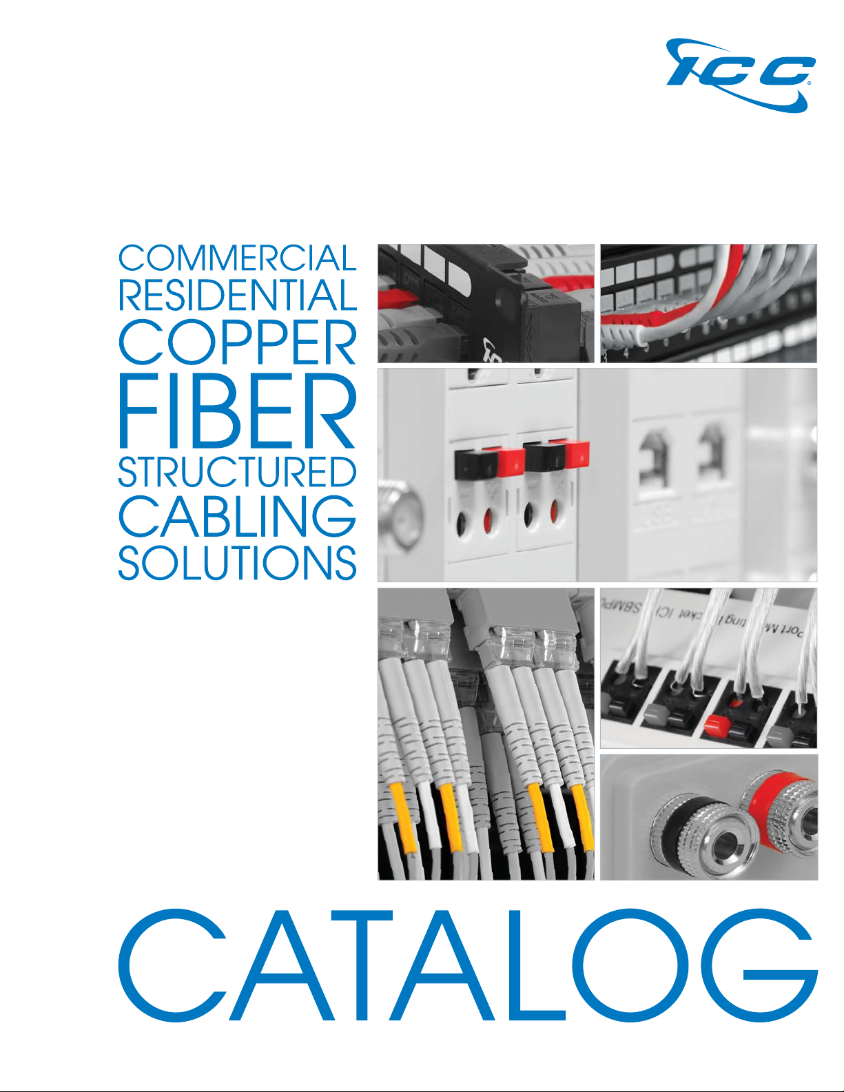
Page 1
C13
Page 2

TABLE OF CONTENTS
WORK AREA OUTLETS
CAT 6A/6/5e connectors .......04
Integrated VDV outlets ..........10
Audio/Video connectors ......12
Confi gurable faceplates .......18
DecorexTM faceplates .............21
Surface mount jacks ...............24
Mounting boxes ......................27
Surface mount boxes .............28
Mobile patch boxes ...............29
MUTOA outlets .........................30
TABLE OF CONTENTS
RACKS & CABLE
MANAGEMENT
Wall mount racks ....................54
Floor mount racks ...................59
Vertical cable managers .......60
Horizontal cable managers ...62
Plastic rings ..............................64
Metal rings ...............................65
Shelves .....................................66
J-Hooks ....................................68
Ladder Rack ............................70
PATCH PANELS &
CROSS-CONNECT
CAT 6A patch panels ............32
CAT 6/5e patch panels .........34
Wall mountable panels .........34
Feed-through panels .............36
Confi gurable blank panels ....37
Telco panels ...........................39
110 wiring blocks ....................40
110 patch panels ...................42
66 wiring blocks .......................44
CORDS & CABLE
ASSEMBLIES
CAT 6A patch cords ...............72
CAT 6 patch cords .................72
CAT 5e patch cords ...............73
110 patch cords .....................74
Telco cables ...........................75
Modular plugs .........................76
Voice line cords ......................77
Velcro® brand cable ties .........78
Nylon cable ties ......................79
PREMISE CABLES
CAT 6A UTP/FTP ......................48
CAT 6e UTP ...............................48
CAT 6 UTP .................................50
CAT 5e .....................................50
FIBER OPTIC SYSTEM
Plug and Play cassettes .........82
Adapters .................................84
Patch panels ..........................85
Rack mount enclosures ..........86
Wall mount enclosures ...........89
Splice trays ..............................90
Couplers ..................................91
MUTOA boxes .........................92
Multimedia outlets .................93
Cable assemblies ..................94
RESIDENTIAL ENCLOSURES
Metal enclosure combos .......96
Plastic enclosure combos .....98
Voice modules ......................102
CAT 6/5e data modules .......103
Video modules ......................104
Multi-media patch panels ...105
Electrical power strip ............105
Electronics bracket ...............105
Cable management covers ..105
PRE-TERMINATED CABLES
HiPerLinkTM copper .................118
HiPerLinkTM fi ber optic .............119
TOOLS & ACCESSORIES
JackEasyTM tool .......................106
110/66 punch-down tool ....107
4-Pair punch-down tool ......108
5-Pair punch-down tool ......108
Cable stripping tools ...........109
Crimping tools .......................109
Compression tools ................110
Compression connectors .....111
Wire cutters ...........................112
Raceway cutter ....................112
INDEX
Part number index ................120
RACEWAY
Runway sections ...................114
Compatible outlets...............115
Connecting accessories ......116
Slotted wiring ducts .............117
Solid wiring ducts .................117
WIRING DIAGRAMS
T568A/B wiring .......................122
ICC is an independent and privately owned California corporation. ICC has been
manufacturing structured cabling products for small and mid-size installers since 1984.
2
888.ASK.4ICC | csr@icc.com | icc.com
Page 3
HD or EZ
®
High Density
Up to 48-Ports in 1 RMS
HD Outlets
DecorexTM and Furniture
HD Panels
Single row ports
Easy
Easy to lay wires
EZ® Outlets
Classic and Furniture
EZ® Panel
Staggered ports
One Tool For Both
Be Green, Buy ValuePacks!
We created ValuePacks to shrink storage size, reduce packaging waste, and lower unit cost. Look for
ValuePacks throughout the catalog to save space, save Mother Earth, and save money.
Connectors
Faceplates Patch Cords 66 Blocks
3
Page 4
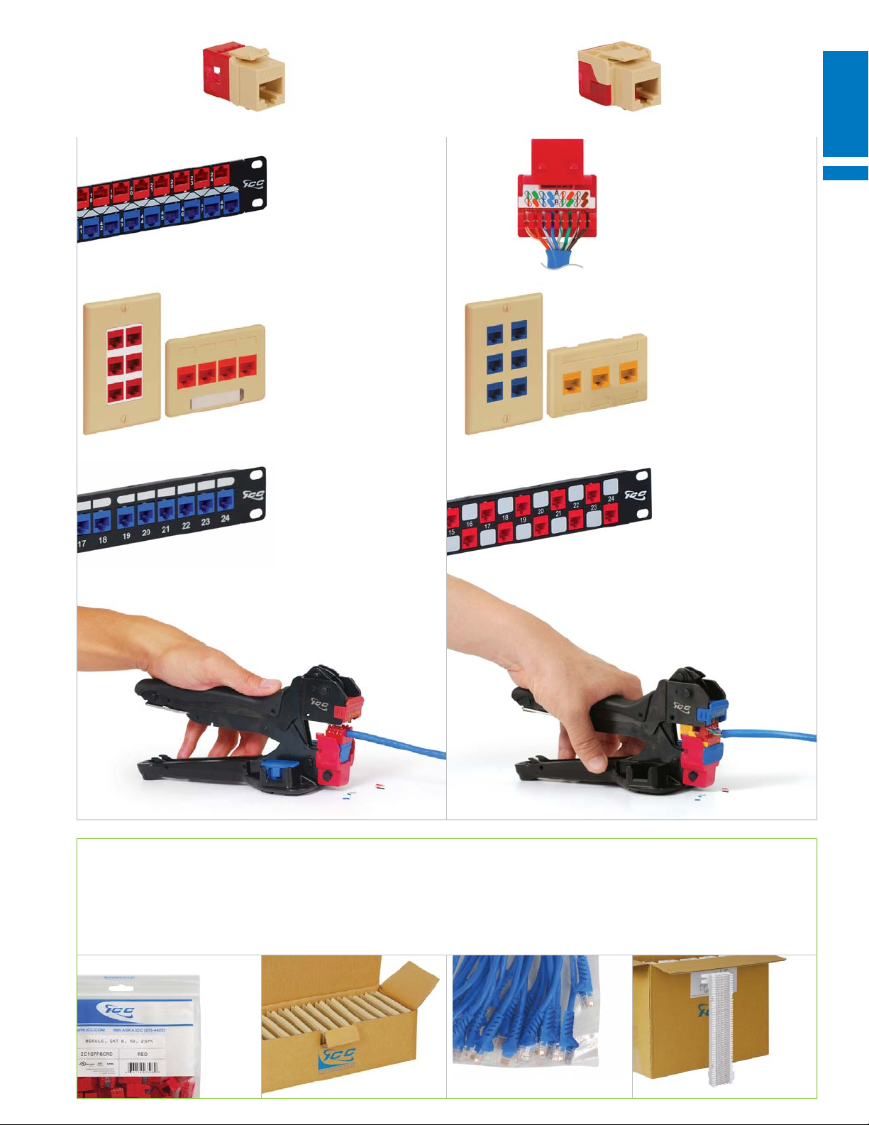
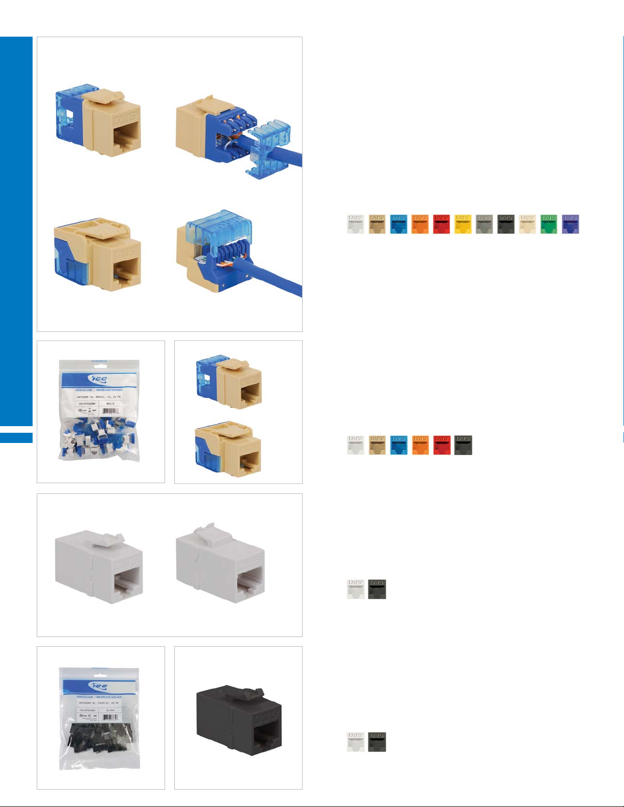
WORK AREA OUTLETS CAT 6A CONNECTORS
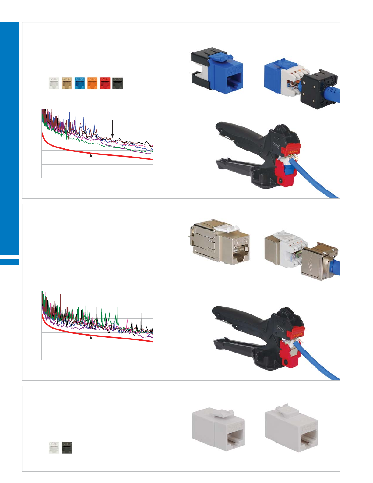
CAT 6A 10G UTP MODULAR CONNECTORS HD STYLE
• Rear split-back IDC
• Shielded termination cap
• 50 micro-inch gold plated contacts
PART NO. DESCRIPTION CARTON / CASE
IC1078GAxx¹ 8P8C, UTP 50 / 400
Color (xx¹) = WH IV BL OR RD BK
PERMANENT LINK PERFORMANCE TEST
100
80
60
WORK AREA OUTLETS
40
NEXTdB
Signal transmission
Headroom
20
0
0500
Installed with ICC premise cable and tested per TIA Permanent Link specifi cation
CAT 6A 10G FTP MODULAR CONNECTOR HD STYLE
O
• 360
shielding from Electromagnetic Interference and Alien Crosstalk
TIA standard limit
Frequency (MHz)
• Rear split-back IDC
• 50 micro-inch gold plated contacts
PART NO. DESCRIPTION CARTON / CASE
IC1078S6A0 8P8C, FTP 50 / 400
ICACSGK6AS Grounding wire, 18 AWG, 7" length, 10 pcs.
PERMANENT LINK PERFORMANCE TEST
100
80
60
40
NEXTdB
20
0
0500
Installed with ICC premise cable and tested per TIA Permanent Link specifi cation
CAT 6A 10G UTP MODULAR COUPLER HD STYLE
TIA standard limit
Frequency (MHz)
• No termination required; feed-through the front and rear
• Joins two high performance CAT 6A patch cords
• 50 micro-inch gold plated contacts
PART NO. DESCRIPTION CARTON / CASE
IC107C6Axx¹ 8P8C, UTP 50 / 400
Color (xx¹) = WH BK
4
888.ASK.4ICC | csr@icc.com | icc.com | MPS
Page 5
WORK AREA OUTLETS CAT 6 CONNECTORS
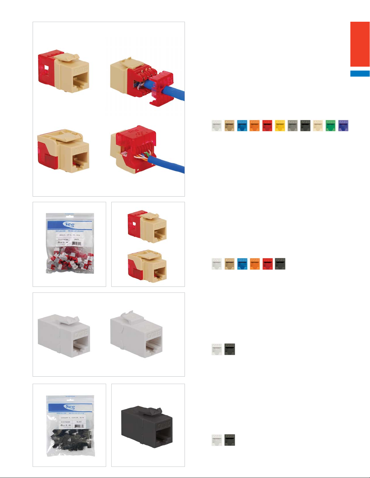
CAT 6 HD AND EZ® STYLE MODULAR CONNECTORS
A.
• Exceeds TIA-568 CAT 6 performance standard
• Built-in PCB technology for maximum signal quality
• 50 micro-inch gold plated contacts
• Includes a color T568A/B wiring diagram
• Terminate with the JackEasy termination tool
PART NO. DESCRIPTION CARTON / CASE
A. IC1078F6xx¹ 8P8C, HD style 50 / 400
• Rear split-back IDC
B. IC1078L6xx¹ 8P8C, EZ style
50 / 400
• Rear in-line IDC makes seating wires easy
• Pair-to-pair wiring; no splitting
B.
Color (xx¹) = WH IV BL OR RD YL GY BK AL GN PR
CAT 6 HD AND EZ® STYLE MODULAR CONNECTOR VALUEPACKS
• Packaged in a resealable bag for easy storage
• Reduces packaging waste
A.
B.
• 25 pieces per bag
PART NO. DESCRIPTION CARTON / CASE
A. IC107F6Cxx¹ 8P8C, HD style , 25 pcs. 10 / 40
B. IC107L6Cxx¹ 8P8C, EZ style, 25 pcs. 10 / 40
Color (xx¹) = WH IV BL OR RD BK
CAT 6 MODULAR COUPLERS HD STYLE
• No termination required; feed-through the front and rear
• Exceeds TIA-568 CAT 6 performance standard
• 50 micro-inch gold plated contacts
PART NO. DESCRIPTION CARTON / CASE
IC107CP6xx¹ 8P8C 50 / 400
Color (xx¹) = WH BK
CAT 6 MODULAR COUPLER HD STYLE VALUEPACKS
• Packaged in a resealable bag for easy storage
• Reduces packaging waste
• 25 pieces per bag
PART NO. DESCRIPTION CARTON / CASE
IC107C6Cxx¹ 8P8C, 25 pcs. 10 / 40
Color (xx¹) = WH BK
5
Page 6
WORK AREA OUTLETS CAT 5e CONNECTORS
CAT 5e HD AND EZ® STYLE MODULAR CONNECTORS
A.
• Exceeds TIA-568 CAT 5e performance standard
• Built-in PCB technology for maximum signal quality
• 50 micro-inch gold plated contacts
• Includes a color T568A/B wiring diagram
• Compatible with VoIP phone systems
• Terminate with the JackEasy termination tool
PART NO. DESCRIPTION CARTON / CASE
A. IC1078F5xx¹ 8P8C, HD style 50 / 400
• Rear split-back IDC
B.
WORK AREA OUTLETS
A.
B.
B. IC1078E5xx¹ 8P8C, EZ style
50 / 400
• Rear in-line IDC makes seating wires easy
• Pair-to-pair wiring; no splitting
Color (xx¹) = WH IV BL OR RD YL GY BK AL GN PR
CAT 5e HD AND EZ® STYLE MODULAR CONNECTOR VALUEPACKS
• Packaged in a resealable bag for easy storage
• Reduces packaging waste
• 25 pieces per bag
PART NO. DESCRIPTION CARTON / CASE
A. IC107F5Cxx¹ 8P8C, HD style, 25 pcs. 10 / 40
B. IC107E5Cxx¹ 8P8C, EZ style, 25 pcs. 10 / 40
Color (xx¹) = WH IV BL OR RD BK
CAT 5e MODULAR COUPLERS HD STYLE
• No termination required; feed-through the front and rear
• Exceeds TIA-568 CAT 5e performance standard
• 50 micro-inch gold plated contacts
PART NO. DESCRIPTION CARTON / CASE
IC107C5Exx¹ 8P8C 50 / 400
Color (xx¹) = WH BK
CAT 5e MODULAR COUPLER HD STYLE VALUEPACKS
• Packaged in a resealable bag for easy storage
• Reduces packaging waste
• 25 pieces per bag
PART NO. DESCRIPTION CARTON / CASE
IC107C5Cxx¹ 8P8C, 25 pcs. 10 / 40
Color (xx¹) = WH BK
6
888.ASK.4ICC | csr@icc.com | icc.com | MPS
Page 7
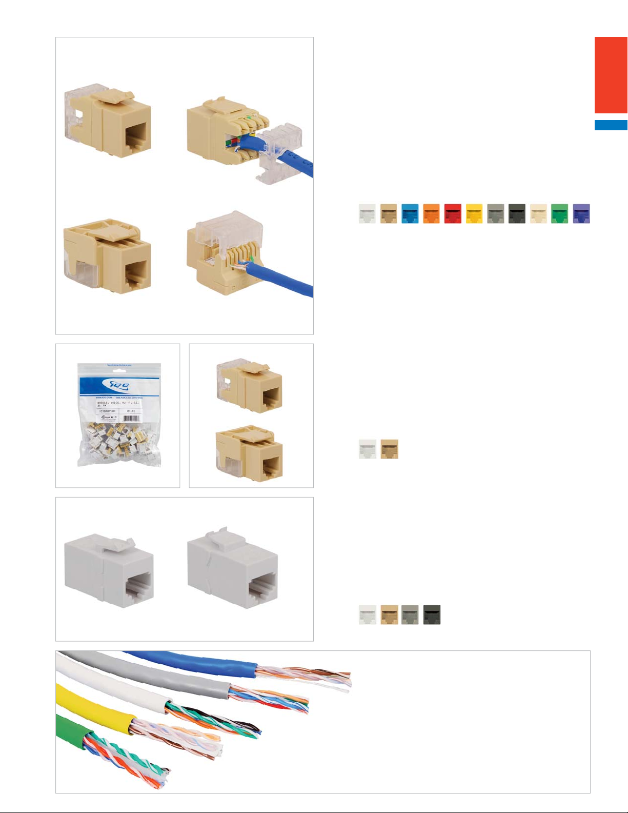
WORK AREA OUTLETS VOICE CONNECTORS
VOICE HD AND EZ® STYLE MODULAR CONNECTORS
A.
• Supports phone applications
• Compatible with RJ-11 plug
• Accepts category-rated cable and 22~24 AWG solid wire
• 50 micro-inch gold plated contacts
• Includes a color USOC/UTP wiring diagram
• Terminate with the JackEasy termination tool
PART NO. DESCRIPTION CARTON / CASE
A. IC1076F0xx¹ 6P6C, HD style 50 / 400
• Rear split-back IDC
B. IC1076V0xx¹ 6P6C, EZ style
50 / 400
• Rear in-line IDC makes seating wires easy
B.
Color (xx¹) = WH IV BL OR RD YL GY BK AL GN PR
VOICE HD AND EZ® STYLE MODULAR CONNECTOR VALUEPACKS
• Packaged in a resealable bag for easy storage
• Reduces packaging waste
A.
B.
• 25 pieces per bag
PART NO. DESCRIPTION CARTON / CASE
A. IC1076FCxx¹ 6P6C, HD style, 25 pcs. 10 / 40
B. IC1076VCxx¹ 6P6C, EZ style, 25 pcs. 10 / 40
Color (xx¹) = WH IV
VOICE MODULAR COUPLERS HD STYLE
• No termination required; feed-through on the front and rear
• Supports phone applications
• Compatible with RJ-11 plug
• 50 micro-inch gold plated contacts
PART NO. DESCRIPTION CARTON / CASE
IC107C6Sxx¹ 6P6C, Pin 1-6 50 / 400
IC107C6Rxx¹ 6P6C, Pin 1-1 50 / 400
Color (xx¹) = WH IV GY BK
One Vendor, No Compatibility Issue
We fi ne tune premise cables and connectivity
outlets to work together as End-to-End solutions.
Page 46
7
Page 8
WORK AREA OUTLETS FIBER OPTIC COUPLERS
FIBER OPTIC MODULAR COUPLERS HD STYLE
• Female to female coupler
• Feed-through on the front and rear; no termination required
• Designed with ceramic sleeves
• Supports multimode and single-mode
PART NO. DESCRIPTION CARTON / CASE
A. IC107LC2xx¹ LC duplex coupler, ceramic sleeves 50 / 400
B. IC107SC2xx¹ SC simplex coupler, ceramic sleeve 50 / 400
C. IC107ST2xx¹ ST simplex coupler, ceramic sleeve 50 / 400
Color (xx¹) = WH IV
WORK AREA OUTLETS
A.
B.
C.
FIBER OPTIC COUPLERS IN ELITE™ SURFACE MOUNT BOXES
Elite surface mount box
Page 28
Snap-in design
8
888.ASK.4ICC | csr@icc.com | icc.com | MPS
Page 9
WORK AREA OUTLETS
B. C. A.
• Fiber couplers are integrated into the bezel
• Designed with metal sleeves
FIBER OPTIC ELITE™ BEZELS
• Install bezels in Elite
TM
series faceplates, outlets and MUTOA boxes
• Package includes icons
PART NO. DESCRIPTION
A. IC108BFCxx¹ SC duplex to SC duplex, fl at
B. IC108BFDxx¹ 2 SC duplex to SC duplex, fl at
C. IC108BACxx¹ SC duplex to SC duplex, angled
E. Front D.
B.A.
E. Rear
D. IC108BFTxx¹ ST duplex to ST duplex, fl at
E. IC108BFRxx¹ SC duplex to ST duplex, fl at
Color (xx¹) = WH IV
FIBER OPTIC SLIM BEZELS
• Fiber couplers are integrated into the bezel
• Install slim bezels inside the bottom of Elite
PART NO. DESCRIPTION
A. ICFOBWLBxx¹ Dual LC duplex to LC duplex, metal sleeves
B. ICFOBWCBxx¹ SC duplex to SC duplex, metal sleeves
C. ICFOBWTBxx¹ ST duplex to ST duplex, metal sleeves
Color (xx¹) = WH IV GY
TM
multimedia outlets
C.
ELITE™ MULTIMEDIA OUTLETS AND MUTOA BOXES ARE CONFIGURABLE WITH ELITE BEZELS AND SLIM BEZELS
Elite multimedia outlet
Two bezel openings on the front
Page 31
Slim bezels mount inside the
bottom of multimedia outlets
allowing fi ber to enter and
exit vertically.
9
Page 10
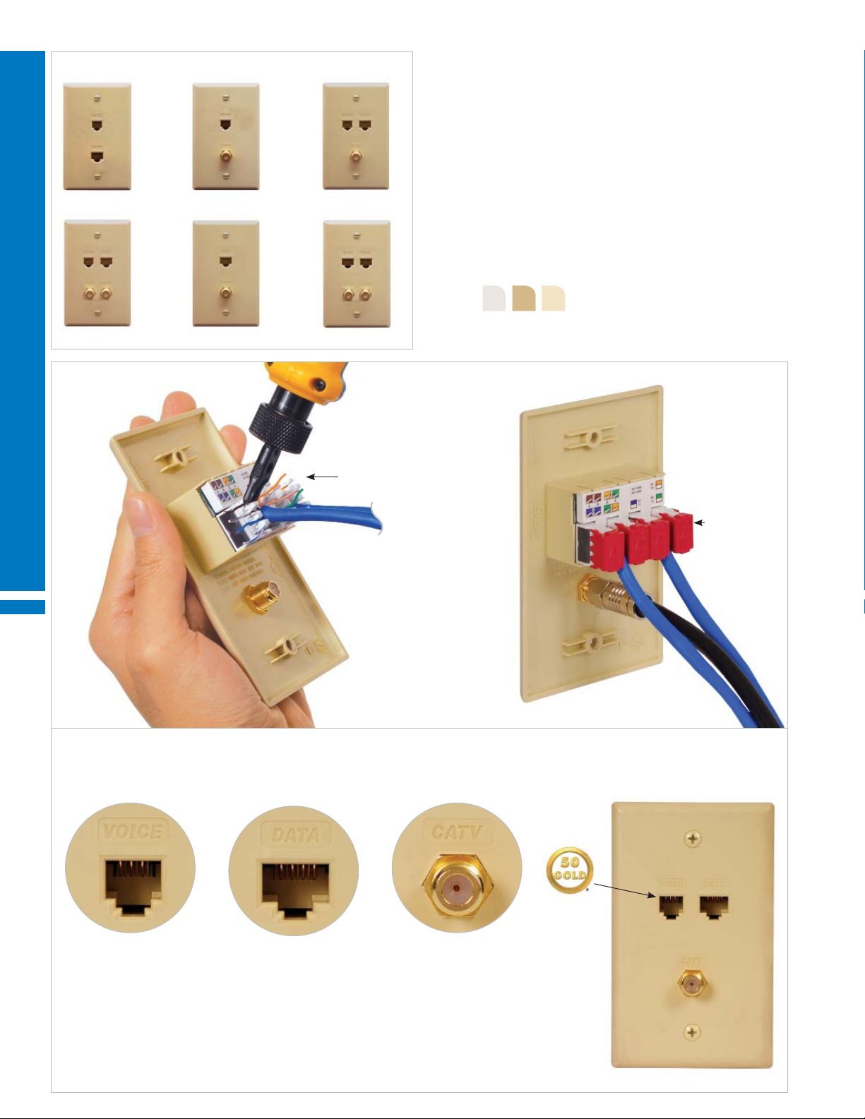
WORK AREA OUTLETS RESIDENTIAL OUTLETS
A.
D.
WORK AREA OUTLETS
FACEPLATE FEATURES
B.
C.
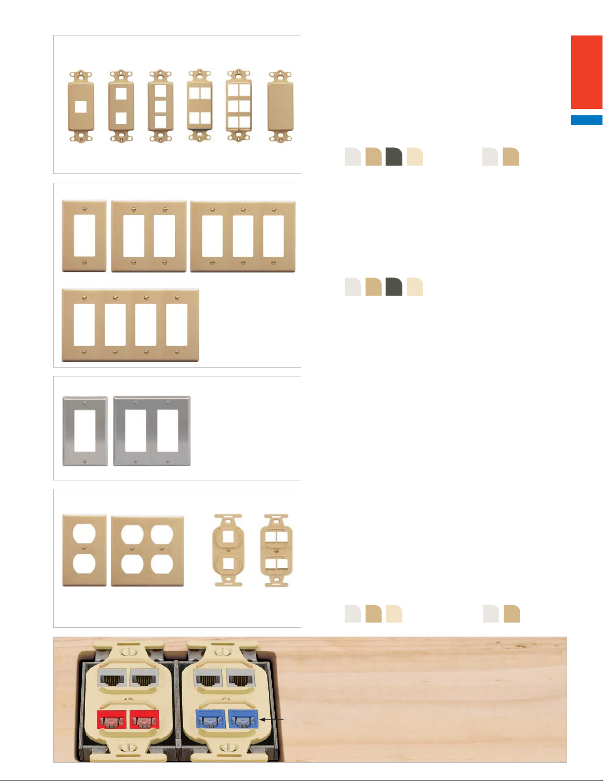
INTEGRATED FACEPLATES WITH VOICE, CAT 5e DATA AND VIDEO
• Integrate all the connectivity into one faceplate
• One-piece design; no assembly required
• Designed with rear 110-Type IDC for fast termination
• Durable ABS plastic body
• 50 micro-inch gold plated contacts
• Package includes retention caps to secure wiring
PART NO. DESCRIPTION CARTON / CASE
E.
F.
A. ICRDSV05xx¹ 6P6C voice and CAT 5e data 25 / 100
B. ICRDSVF0xx¹ 6P6C voice and F-Type video 25 / 100
C. ICRDSVF5xx¹ 6P6C voice, CAT 5e data and F-Type video 25 / 100
D. ICRDSV25xx¹ 6P6C voice, CAT 5e data and 2 F-Type video 25 / 100
E. ICRDS0F5xx¹ CAT 5e data and F-Type video 25 / 100
F. ICRDS2F5xx¹ 2 CAT 5e data and 2 F-Type video 25 / 100
Color (xx¹) = WH IV AL
IDC contacts
Retention caps
INTEGRATED FACEPLATE FEATURES
All ports are embossed to identify applications. All modular connectors have 50 micro inch gold plated contacts for maximum performance.
10
Voice Port
Supports:
• Phones
• Fax machines
CAT 5e Data Port
Supports:
• Home networking
• 1 Gigabit per second
• High speed internet
F-Type Port
Supports:
• 2 GHz bandwidth
• Televisions
• Satellite
• Cable
888.ASK.4ICC | csr@icc.com | icc.com | MPS
Page 11
WORK AREA OUTLETS SURFACE MOUNT BOXES
CLASSIC SURFACE MOUNT BOXES KITTED WITH VOICE AND CAT 5e DATA MODULAR CONNECTORS
• Comes with a voice or CAT 5e, EZ
®
style, modular connector
• Connectors are removable
• Package includes adhesive strips and wood screws for mounting
A.
B.
PART NO.
DESCRIPTION
A. IC625SV1xx¹ 1-Port box, with voice EZ connector
B. IC625SV2xx¹ 2-Port box with 2 voice EZ connectors
SURFACE MOUNT BOX KIT FEATURES
C.
D.
C. IC625S51xx¹ 1-Port box with CAT 5e EZ connector
D. IC625S52xx¹ 2-Port box with 2 CAT 5e EZ connectors
Color (xx¹) = WH IV
Removable cover
Removable side knockoutsRemovable cover
Snap-in design
.30" H
Rear cable exit
.30" W
110-Type IDC makes terminating fast
Port labeling area
Port labeling areasRemovable side knockouts
.43" H
Rear cable exit
.30" W
11
Page 12
WORK AREA OUTLETS
HDMI MODULAR COUPLERS HD STYLE
• Female to female gold plated coupler
• Supports high-defi nition video: 1080p, 3D and HDCP
PART NO. DESCRIPTION CARTON / CASE
IC107HDMxx¹ HDMI connector 50 / 400
Color (xx¹) = WH IV BK AL
A. B.
WORK AREA OUTLETS
USB MODULAR COUPLERS HD STYLE
• Female to female coupler
PART NO. DESCRIPTION CARTON / CASE
A. IC107UAAWH USB coupler, A-to-A 50 / 400
• Supports USB connectivity; backwards compatible
B. IC107UABWH USB coupler, A-to-B
50 / 400
• Supports USB connectivity
• Reversible coupler with either the A or B port facing outward
Color = White
3.5mm STEREO AUDIO PLUG MODULAR CONNECTORS HD STYLE
• Rear push-pins accept UTP cable or any 22~24 AWG wire
• Terminals are marked for correct polarity
PART NO. DESCRIPTION CARTON / CASE
IC107SAPxx¹ 3.5mm connector to push pin 50 /400
Color (xx¹) = WH IV BK AL
12
3.5mm STEREO AUDIO PLUG MODULAR COUPLERS HD STYLE
• Female to female nickel plated coupler
PART NO. DESCRIPTION CARTON / CASE
IC107SACWH 3.5mm coupler, feed-through 50 / 400
Color = White
S-VIDEO MODULAR CONNECTORS HD STYLE
• Front female connector with rear 110-Type IDC termination
• Rear IDC accepts UTP cable or any 22~24 AWG wire
• Package includes a termination cap to secure wiring
PART NO. DESCRIPTION CARTON / CASE
IC107SVIxx¹ S-Video connector 50 / 400
Color (xx¹) = WH IV BK AL
888.ASK.4ICC | csr@icc.com | icc.com | MPS
Page 13
WORK AREA OUTLETS
HDMI DÉCOREX™ INSERTS WITH 2 OPEN HIGH DENSITY PORTS
• Female to female gold plated coupler
• Supports high-defi nition video: 1080p, 3D and HDCP
• Package includes 2 blank modular inserts
PART NO. DESCRIPTION CARTON / CASE
IC107DH2xx¹ 1 HDMI coupler, 2 HD ports 25 / 200
Color (xx¹) = WH IV BK AL
DUAL HDMI DÉCOREX INSERTS WITH 2 OPEN HIGH DENSITY PORTS
• Female to female gold plated couplers
• Supports high-defi nition video: 1080p, 3D and HDCP
• Package includes 2 blank modular inserts
PART NO. DESCRIPTION CARTON / CASE
IC107DDHxx¹ 2 HDMI couplers, 2 HD ports 25 / 200
Color (xx¹) = WH IV BK AL
VGA DÉCOREX INSERTS WITH 2 OPEN HIGH DENSITY PORTS
• Female to female 15-Pin VGA coupler
• Supports high quality analog video
• Package includes 2 blank modular inserts
PART NO. DESCRIPTION CARTON / CASE
IC107DR2xx¹ 1 VGA coupler, 2 HD ports 25 / 200
Color (xx¹) = WH IV BK AL
VGA DÉCOREX INSERTS WITH 4 OPEN HIGH DENSITY PORTS
• Female to female 15-Pin VGA coupler
• Supports high quality analog video
• Package includes 4 blank modular inserts
PART NO. DESCRIPTION CARTON / CASE
IC107DR4xx¹ 1 VGA coupler, 4 HD ports 25 / 200
Color (xx¹) = WH IV BK AL
VGA Décorex Inserts
Connecting to computer monitors,
projectors and fl at screen TV's from
the wall outlet.
13
Page 14
WORK AREA OUTLETS VIDEO CONNECTORS
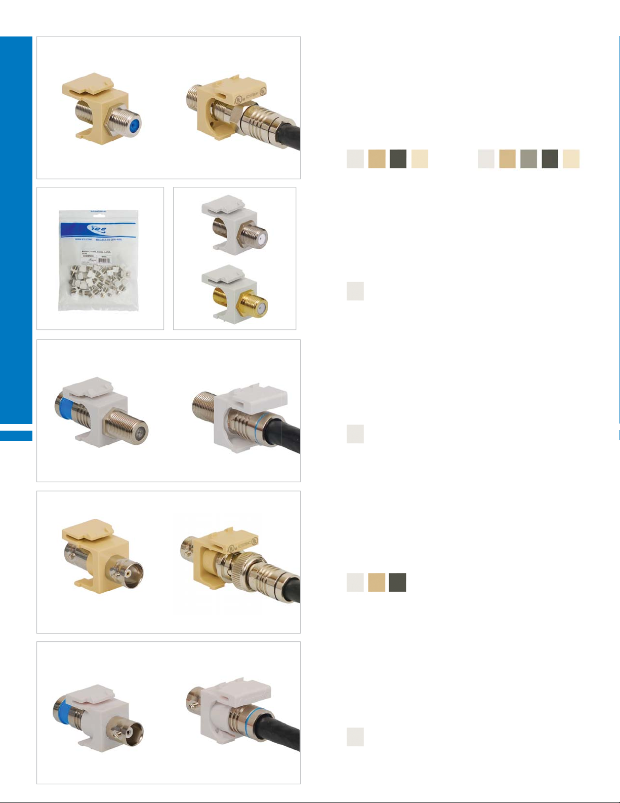
F-TYPE VIDEO MODULAR CONNECTORS HD STYLE
A.
• Female to female feed-through connector
• Threaded connector to secure connection
• Works with RG-6 and RG-59 coaxial cable
PART NO. DESCRIPTION CARTON / CASE
A. IC107B9Fxx¹ F-Type nickel plated, 3 GHz (pictured) 50 / 400
IC107B9Gxx¹ F-Type gold plated, 3 GHz 50 / 400
IC107B5Fxx² F-Type nickel plated, 2 GHz 50 / 400
IC107B5Gxx² F-Type gold plated, 2 GHz 50 / 400
Color (xx¹) = WH IV BK AL Color (xx2) = WH IV GY BK AL
F-TYPE VIDEO MODULAR CONNECTOR HD STYLE VALUEPACKS
• Packaged in a resealable bag for easy storage
• Reduces packaging waste
WORK AREA OUTLETS
A.
B.
• 25 pieces per bag
PART NO. DESCRIPTION CARTON / CASE
A. IC107BFCWH F-Type nickel plated, 2 GHz, 25 pcs. 10 / 40
B. IC107BGCWH F-Type gold plated, 2 GHz, 25 pcs. 10 / 40
Color = White
F-TYPE VIDEO MODULAR COMPRESSION CONNECTOR HD STYLE
• Front female nickel plated connector with rear compression connector
• Rear compression connector works with RG-6 quad shield coaxial cable
• Not compatible with plenum cable
PART NO. DESCRIPTION CARTON / CASE
IC107FQGWH F-Type, RG-6Q, blue band 50 / 400
Color = White
BNC VIDEO MODULAR CONNECTORS HD STYLE
• Female to female feed-through nickel plated connector
• Supports CCTV, NTSC Analog video signals and satellite link signals
PART NO. DESCRIPTION CARTON / CASE
IC107BNCxx¹ BNC connector, 75 Ohm 50 / 400
IC107B3Gxx¹ BNC connector, 50 Ohm 50 / 400
Color (xx¹) = WH IV BK
14
BNC VIDEO MODULAR COMPRESSION CONNECTOR HD STYLE
• Front female nickel plated connector with rear compression connector
• Rear compression connector works with RG-6 quad shield coaxial cable
• Not compatible with plenum cable
PART NO. DESCRIPTION CARTON / CASE
IC107BQCWH BNC, blue band, 75 Ohm 50 / 400
Color = White
888.ASK.4ICC | csr@icc.com | icc.com | MPS
Page 15

WORK AREA OUTLETS AUDIO AND VIDEO CONNECTORS
RCA FEMALE-TO-RCA FEMALE MODULAR CONNECTORS HD STYLE
A.
• Female to female feed-through connector
PART NO. DESCRIPTION CARTON / CASE
A. IC107R6Gxx¹ Red insert (pictured) 50 / 400
IC107G6Gxx¹ Green insert 50 / 400
IC107L6Gxx¹ Blue insert 50 / 400
IC107B6Gxx¹ White insert 50 / 400
IC107Y6Gxx¹ Yellow insert 50 / 400
IC107K6Gxx¹ Black insert 50 / 400
Color (xx¹) = WH IV BK AL
RCA FEMALE-TO-F-TYPE MODULAR CONNECTORS HD STYLE
A.
• Front female connector with rear F-Type female connector
• Rear connector works with RG-6 and RG-59 coaxial cable
PART NO. DESCRIPTION CARTON / CASE
A. IC107RFGxx¹ Red Insert (pictured) 50 / 400
IC107GFGxx¹ Green Insert 50 / 400
IC107LFGxx¹ Blue Insert 50 / 400
IC107BFGxx¹ White Insert 50 / 400
IC107YFGxx¹ Yellow Insert 50 / 400
IC107KFGxx¹ Black Insert 50 / 400
Color (xx¹) = WH IV BK AL
A.
A.
RCA FEMALE-TO-IDC MODULAR CONNECTORS HD STYLE
• Front female connector with rear 110-Type IDC termination
• Rear IDC accepts UTP cable or any 22~24 AWG wire
• Package includes a termination cap to secure wiring
PART NO. DESCRIPTION CARTON / CASE
A. IC107R8Gxx¹ Red insert (pictured) 50 / 400
IC107G8Gxx¹ Green insert 50 / 400
IC107L8Gxx¹ Blue insert 50 / 400
IC107B8Gxx¹ White insert 50 / 400
IC107Y8Gxx¹ Yellow insert 50 / 400
IC107K8Gxx¹ Black insert 50 / 400
Color (xx¹) = WH IV BK AL
RCA MODULAR COMPRESSION CONNECTORS HD STYLE
• Front female nickel plated connector with rear compression connector
• Rear compression connector works with RG-6 quad shield coaxial cable
• Not compatible with plenum cable
PART NO. DESCRIPTION CARTON / CASE
A. IC107RQRWH Red insert, blue band (pictured) 50 / 400
IC107RQGWH Green insert, blue band 50 / 400
IC107RQLWH Blue insert, blue band 50 / 400
IC107RQWWH White insert, blue band 50 / 400
IC107RQYWH Yellow insert, blue band 50 / 400
IC107RQKWH Black insert, blue band 50 / 400
Color = White
A. B.
RCA SOLDER TAIL AND COMPONENT PACK MODULAR CONNECTORS
PART NO. DESCRIPTION
A. IC107B7Gxx¹ Solder Tail, Black Insert, HD style
• Front female connector with rear solder tail termination
B. IC107RR5xx
IC107RF5xx
IC107RD5xx
2
Female to female connector, HD style, 5 pcs. (pictured)
2
Front female with rear F-Type female, HD style, 5 pcs.
2
Front female with rear 110-Type IDC termination, HD style, 5 pcs.
• Includes connectors with 2 red, 1 green, 1 blue and 1 white insert
• 5 pieces per bag
Color (xx¹) = WH IV AL Color (xx2) = WH IV BK AL
15
Page 16
WORK AREA OUTLETS AUDIO SPEAKER CONNECTORS
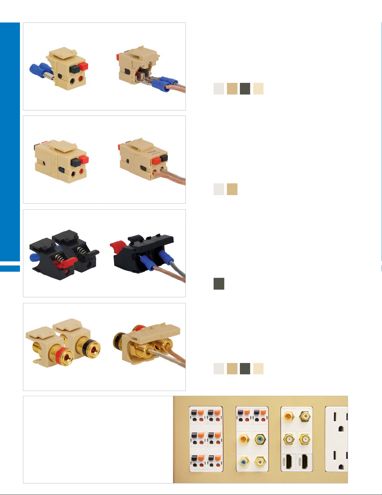
DUAL AUDIO SPEAKER MODULAR CONNECTORS HD STYLE
• Front push buttons with rear crimp-on wire connector
• Black and red push buttons have + and - signs for correct polarity
• Accepts speaker wire up to 16 AWG
• Patented design
PART NO. DESCRIPTION CARTON / CASE
IC107DSCxx¹ Front speaker connector 50 / 400
Color (xx¹) = WH IV BK AL
DUAL FRONT AND BACK AUDIO SPEAKER MODULAR CONNECTORS
HD STYLE
• Front and rear push buttons
WORK AREA OUTLETS
• Black and red push buttons have + and - signs for correct polarity
• Accepts speaker wire up to 16 AWG
• Patented design
PART NO. DESCRIPTION CARTON / CASE
IC107DSBxx¹ Front and rear speaker connector 50 / 400
Color (xx¹) = WH IV
SPRING CLIP AUDIO SPEAKER MODULAR CONNECTORS HD STYLE
• Front spring clip with rear crimp-on wire connector
• Front accepts speaker wire up to 12 AWG
• Rear accepts speaker wire up to 16 AWG
• Comes in pairs with red and black clips for correct polarity
• Patented design
PART NO. DESCRIPTION CARTON / CASE
IC107BSSBK Spring clip connectors 50 / 400
Color = Black
BINDING POST AUDIO SPEAKER MODULAR CONNECTORS HD STYLE
• Front gold plated binding post with female banana plug
• Rear set-screw connection
• Accepts speaker wire up to 8 AWG
• Comes in pairs with red and black bands for correct polarity
PART NO. DESCRIPTION CARTON / CASE
IC107PMGxx¹ Binding post connectors, gold plated 50 / 400
Color (xx¹) = WH IV BK AL
16
Home Theater Solution
Install 7.1 surround sound, high
defi nition and component A/V as
well as satellite and cable input in
a DécorexTM quad-gang faceplate.
888.ASK.4ICC | csr@icc.com | icc.com | MPS
Page 17
WORK AREA OUTLETS AUDIO AND VIDEO CONNECTORS
A. B. C.
A. B. C.
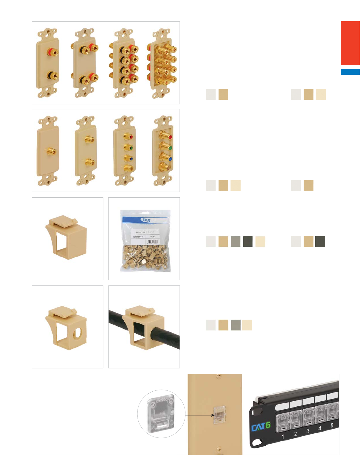
BINDING POST AUDIO SPEAKER DÉCOREX™ INSERTS
• Front gold plated binding post with female banana plug
• Rear set-screw connection
• Accepts speaker wire up to 8 AWG
• Red and black bands for correct polarity
PART NO. DESCRIPTION
A. ICRDSSBPxx¹ 2 binding posts
B. ICRDSDBPxx² 4 binding posts
C. ICRDSQBPxx² 8 binding posts
Color (xx¹) = WH IV Color (xx2) = WH IV AL
F-TYPE AND RCA DÉCOREX INSERTS
PART NO. DESCRIPTION
A. IC630DSFxx¹ F-Type connector
B. IC630DDFxx¹ 2 F-Type connectors
• Female to female F-Type connector
C. ICRDS3RFxx² F-Type connector and 3 RCA connectors
• Female to female F-Type connector
• 3 RCA female connectors with rear F-Type connectors
• Rear works with RG-6 and RG-59 coaxial cable
Color (xx¹) = WH IV AL Color (xx2) = WH IV
A. B.
BLANK FILL-IN MODULAR INSERTS HD STYLE
• Fills open and unused ports until they are needed
PART NO. DESCRIPTION CARTON / CASE
A. IC107BN0xx¹ Blank fi ll-in insert, 10 pcs. 25 / 200
B. IC107BNVxx² Blank fi ll-in insert, 100 pcs. VALUEPACK
Color (xx¹) = WH IV GY BK AL Color (xx2) = WH IV BK
CABLE FEED-THROUGH MODULAR INSERTS HD STYLE
• Allows cable to pass through a 0.30 inch diameter hole
PART NO. DESCRIPTION CARTON / CASE
IC107BN2xx¹ Cable feed-through insert, 10 pcs. 75 / 300
Color (xx¹) = WH IV GY AL
DUST COVER
• Works with CAT 6A, CAT 6, CAT 5e and voice
modular connectors and patch panels
• Snaps on the port opening to prevent dust
from entering
PART NO. DESCRIPTION
ICACSDCICL Dust cover, 10 pcs.
ICACSDCVCL Dust cover, 100 pcs.
Color = Clear
VALUEPACK
17
Page 18
WORK AREA OUTLETS FACEPLATES
A. B. C. D. E.
F. G .
WORK AREA OUTLETS
H. I.
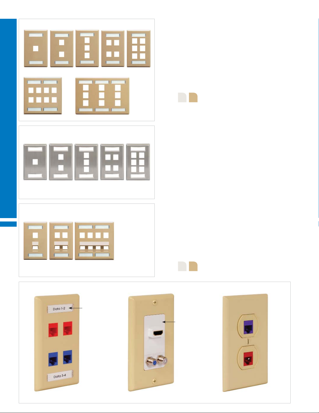
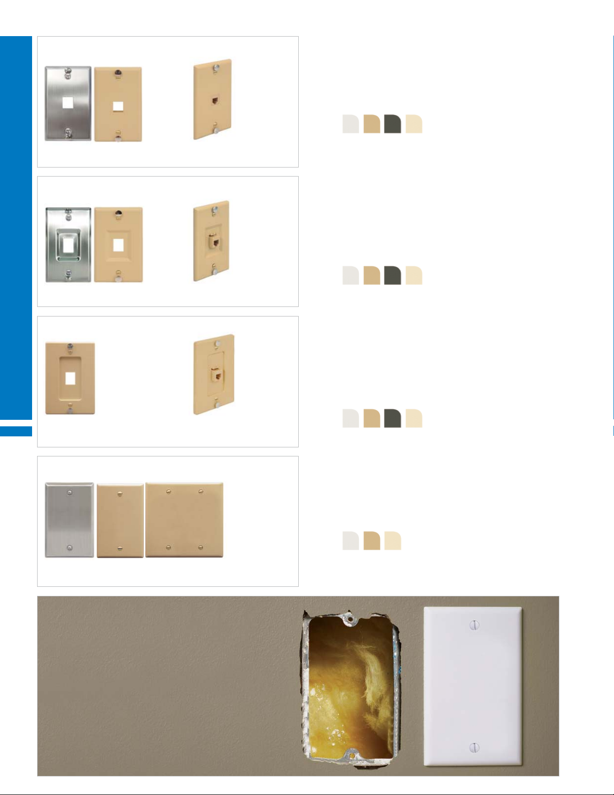
CLASSIC CONFIGURABLE FACEPLATES
• Flush mount style
• Durable ABS plastic
PART NO. DESCRIPTION CARTON / CASE
A. IC107F01xx¹ 1-Port, single gang 25 / 200
B. IC107F02xx¹ 2-Ports, single gang 25 / 200
C. IC107F03xx¹ 3-Ports, single gang 25 / 200
D. IC107F04xx¹ 4-Ports, single gang 25 / 200
E. IC107F06xx¹ 6-Ports, single gang 25 / 200
F. IC107FD8xx¹ 8-Ports, double gang 25 / 100
G. IC107F12xx¹ 12-Ports, double gang 25 / 100
H. IC107FT9xx² 9-Ports, triple gang 25 / 200
I. IC107FT0xx² 12-Ports, triple gang 25 / 100
Color (xx¹) = WH IV GY BK AL Color (xx2) = WH IV GY
CLASSIC CONFIGURABLE FACEPLATE VALUEPACKS
A.
• Packaged in a resealable box for easy storage
• Reduces packaging waste
• 25 pieces per box
PART NO. DESCRIPTION
A. IC107F1Cxx¹ 1-Port, single gang, 25 pcs.
IC107F2Cxx¹ 2-Ports, single gang, 25 pcs.
IC107F3Cxx¹ 3-Ports, single gang, 25 pcs.
IC107F4Cxx¹ 4-Ports, single gang, 25 pcs.
Color (xx¹) = WH IV
CLASSIC CONFIGURABLE FACEPLATE FEATURES
We offer a wide selection of classic faceplates. They are confi gurable with modular connectors, couplers and adapters and are designed to fi t
standard NEMA outlet boxes. Faceplates come in various colors.
Retainer
18
4.50" H
2.75" W
Classic: Traditional design Stainless Steel: Greater durability, easy-to-clean Angled: Reduces cord bending
888.ASK.4ICC | csr@icc.com | icc.com | MPS
Front Rear
Page 19
WORK AREA OUTLETS FACEPLATES
B. C. D. E. A.
F. G.
A. B. C. D. E.
F.
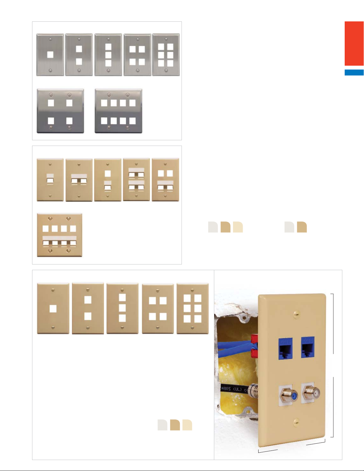
CLASSIC STAINLESS STEEL CONFIGURABLE FACEPLATES
• Flush mount style
• Corrosion resistant 304 stainless steel
PART NO. DESCRIPTION CARTON / CASE
A. IC107SF1SS 1-Port, single gang 25 / 200
B. IC107SF2SS 2-Ports, single gang 25 / 200
C. IC107SF3SS 3-Ports, single gang 25 / 200
D. IC107SF4SS 4-Ports, single gang 25 / 200
E. IC107SF6SS 6-Ports, single gang 25 / 200
F. IC107DF4SS 4-Ports, double gang 25 / 100
G. IC107DF8SS 8-Ports, double gang 25 / 100
CLASSIC ANGLED CONFIGURABLE FACEPLATES
• Angled ports help reduce cable stress
• Flush mount style
• Durable ABS plastic
PART NO. DESCRIPTION CARTON / CASE
A. IC107DA1xx¹ 1-Port angled, single gang 25 / 200
B. IC107DA2xx¹ 2-Ports angled, single gang 25 / 200
C. IC107AF2xx² 1-Port fl at, 1-Port angled, single gang 25 / 200
D. IC107DA4xx¹ 4-Ports angled, single gang 25 / 200
E. IC107AF4xx² 2-Ports fl at, 2-Ports angled, single gang 25 / 200
F. IC107AF8xx² 4-Ports fl at, 4-Ports angled, double gang 25 / 200
Color (xx¹) = WH IV AL Color (xx2) = WH IV
B. C. D. E. A.
CLASSIC OVERSIZED CONFIGURABLE FACEPLATES
• Designed to cover uneven and oversized drywall cuts
• Larger than standard faceplates
• Flush mount style
• Durable ABS plastic
PART NO. DESCRIPTION CARTON / CASE
A. IC107LF1xx¹ 1-Port, single gang 25 / 200
B. IC107LF2xx¹ 2-Ports, single gang 25 / 200
C. IC107LF3xx¹ 3-Ports, single gang 25 / 200
D. IC107LF4xx¹ 4-Ports, single gang 25 / 200
E. IC107LF6xx¹ 6-Ports, single gang 25 / 200
Color (xx¹) = WH IV AL
4.87" H
3.12" W
19
Page 20
WORK AREA OUTLETS FACEPLATES
A. B. C. D. E.
F. G .
WORK AREA OUTLETS
A. B. C. D. E.
CLASSIC CONFIGURABLE FACEPLATES WITH STATION ID
• Flush mount style
• Durable ABS plastic
• Package includes paper labels and clear view covers
PART NO. DESCRIPTION CARTON / CASE
A. IC107S01xx¹ 1-Port, single gang 25 / 200
B. IC107S02xx¹ 2-Ports, single gang 25 / 200
C. IC107S03xx¹ 3-Ports, single gang 25 / 200
D. IC107S04xx¹ 4-Ports, single gang 25 / 200
E. IC107S06xx¹ 6-Ports, single gang 25 / 200
F. IC107SD8xx¹ 8-Ports, double gang 25 / 100
G. IC107ST9xx¹ 9-Ports, triple gang 25 / 100
Color (xx¹) = WH IV
CLASSIC STAINLESS STEEL CONFIGURABLE FACEPLATES WITH STATION ID
• Flush mount style
• Corrosion resistant 304 stainless steel
• Package includes paper labels and clear view covers
PART NO. DESCRIPTION CARTON / CASE
A. IC107S01SS 1-Port, single gang 25 / 200
B. IC107S02SS 2-Ports, single gang 25 / 200
C. IC107S03SS 3-Ports, single gang 25 / 200
D. IC107S04SS 4-Ports, single gang 25 / 200
E. IC107S06SS 6-Ports, single gang 25 / 200
A. B. C.
THREE STYLES OF CONFIGURABLE FACEPLATES
Accept labels up to
1.70” W x 0.40” H
CLASSIC ANGLED CONFIGURABLE FACEPLATES WITH STATION ID
• Angled ports help reduce cable stress
• Flush mount style
• Durable ABS plastic
• Package includes paper labels and clear view covers
PART NO. DESCRIPTION CARTON / CASE
A. IC107AS2xx¹ 1-Port fl at, 1-Port angled, single gang 25 / 200
B. IC107AS4xx¹ 2-Ports fl at, 2-Ports angled, single gang 25 / 200
C. IC107AS8xx¹ 4-Ports fl at, 4-Ports angled, double gang 25 / 200
Color (xx¹) = WH IV
HDMI DécorexTM Inserts
20
Station ID ElectricalDécorex
888.ASK.4ICC | csr@icc.com | icc.com | MPS
Page 21
WORK AREA OUTLETS FACEPLATES
DÉCOREX™ CONFIGURABLE INSERTS
• Inserts are confi gurable with modular connectors
A. B. C. D. E. F.
• Durable ABS plastic
PART NO. DESCRIPTION CARTON / CASE
A. IC107DI1xx¹ 1-Port 50 / 400
B. IC107DI2xx¹ 2-Ports 50 / 400
C. IC107DI3xx¹ 3-Ports 50 / 400
D. IC107DI4xx¹ 4-Ports; works with HD style connectors only 50 / 400
E. IC107DI6xx¹ 6-Ports; works with HD style connectors only 50 / 400
F. IC630DIBxx² Blank insert 50 / 400
Color (xx¹) = WH IV BK AL Color (xx2) = WH IV
A. B. C.
D.
A. B.
DÉCOREX CONFIGURABLE FACEPLATES
• Faceplates are confi gurable with Décorex inserts
• Durable ABS plastic
PART NO. DESCRIPTION CARTON / CASE
A. IC107DFSxx¹ 1-Insert space, single gang 25 / 200
B. IC107DFDxx¹ 2-Insert spaces, double gang 25 / 200
C. IC107DFTxx¹ 3-Insert spaces, triple gang 50 / 200
D. IC107DFQxx¹ 4-Insert spaces, quad gang 25 / 100
Color (xx¹) = WH IV BK AL
DÉCOREX STAINLESS STEEL CONFIGURABLE FACEPLATES
• Faceplates are confi gurable with Décorex inserts
• Corrosion resistant 304 stainless steel
PART NO. DESCRIPTION CARTON / CASE
A. IC107DFSSS 1-Insert space, single gang 25 / 100
B. IC107DFDSS 2-Insert spaces, double gang 25 / 100
A. B. C. D.
HD style
ELECTRICAL CONFIGURABLE FACEPLATES & INSERTS
• Durable ABS plastic
PART NO. DESCRIPTION CARTON / CASE
A. IC106FP2xx¹ 2-Ports, single gang faceplate 25 / 500
B. IC106FP4xx² 4-Ports, double gang faceplate 25 / 250
• Faceplates are confi gurable with electrical inserts
C. IC107DPIxx¹ 2-Ports, insert
D. IC1074PIxx¹ 4-Ports, insert; works with HD style connectors only 50 / 400
50 / 400
• Inserts are confi gurable with modular connectors
Color (xx¹) = WH IV AL Color (xx2) = WH IV
For Electrical Floor Boxes
Electrical inserts are confi gurable with voice,
data, audio, video and fi ber optic modular
connectors. They can also be installed in
NEMA electrical boxes on the fl oor.
21
Page 22
WORK AREA OUTLETS
A. B.
A. B.
WORK AREA OUTLETS
FLUSH CONFIGURABLE TELEPHONE WALL PLATES
• Designed with standoffs to mount phones on walls and vertical surfaces
• Flush mount style
PART NO. DESCRIPTION CARTON / CASE
A. IC107FFWSS 1-Port, single gang, stainless steel 25 / 200
B. IC107FFWxx¹ 1-Port, single gang, ABS plastic 25 / 200
Color (xx¹) = WH IV BK AL
RECESSED CONFIGURABLE TELEPHONE WALL PLATES
• Designed with standoffs to mount phones on walls and vertical surfaces
• Recessed style
• Use color ID caps for a clean appearance
PART NO. DESCRIPTION CARTON / CASE
A. IC107FRWSS 1-Port, single gang, stainless steel 25 / 200
B. IC107FRWxx¹ 1-Port, single gang, ABS plastic 25 / 200
Color (xx¹) = WH IV BK AL
A. B. C.
RECESSED CONFIGURABLE TELEPHONE WALL PLATES
• Designed with standoffs to mount phones on walls and vertical surfaces
• Recessed style
• Durable ABS plastic
• Use color ID caps for a clean appearance
PART NO. DESCRIPTION CARTON / CASE
IC107FWPxx¹ 1-Port, single gang 25 / 200
Color (xx¹) = WH IV BK AL
BLANK FACEPLATES
• Covers open and unused wall outlets until needed
PART NO. DESCRIPTION CARTON / CASE
A. IC630EBSSS Blank, single gang, stainless steel 25 / 200
B. IC630EB0xx¹ Blank, single gang, ABS plastic 25 / 200
C. IC630EBDxx¹ Blank, double gang, ABS plastic 25 / 100
Color (xx¹) = WH IV AL
22
Blank Faceplates
888.ASK.4ICC | csr@icc.com | icc.com | MPS
Page 23
WORK AREA OUTLETS
A.
B.
A. B.
BULK NOSE FACEPLATES
• Faceplates are molded with large opening
• Allows bulky cable to pass through the wall outlet
• Durable ABS plastic
PART NO. DESCRIPTION CARTON / CASE
A. IC640BSSxx¹ Single gang 15 / 120
• 1.25" W x 0.90" D opening
B. IC640BDSxx¹ Double gang
10 / 80
• 2.75" W x 1.15" D opening
Color (xx¹) = WH IV
INTERNATIONAL CONFIGURABLE FACEPLATES
• Works with international wall outlet dimensions
• Spring loaded shutters in ports, prevent dust from entering
• Recessed areas above and below ports for easy labeling
PART NO. DESCRIPTION CARTON / CASE
A. IC107EF1WH 1-Port, 86 mm H x 86 mm W 25 / 200
B. IC107EF2WH 2-Ports, 86 mm H x 86 mm W 25 / 200
Color = White
EURO STYLE CONFIGURABLE ELITE™ MULTIMEDIA BOXES
• Works with international European wall outlet dimensions
• Two-piece design, faceplate and mounting box
• Confi gurable with Elite bezels
• Box is designed with knockouts to work with raceway systems
• Package includes paper labels, clear view covers and mounting screws
PART NO. DESCRIPTION
IC108CE1xx¹ 1-Bezel opening, 83.5 mm H x 83.5 mm W x 55.626 mm D
Color (xx¹) = WH IV GY
Bulk Nose Faceplates
23
Page 24
WORK AREA OUTLETS SCREW TERMINAL OUTLETS
WALL PLATES INTEGRATED WITH VOICE AND VIDEO
• One-piece design; no assembly required
A. B. C. D. E.
• Designed with rear Phillips screw down terminals
• Durable ABS plastic
PART NO. DESCRIPTION CARTON / CASE
A. IC630E60xx¹ 6P6C, single gang 25 / 200
B. IC630E66xx¹ 2 6P6C, single gang 25 / 200
C. IC630EG0xx¹ F-Type, single gang 25 / 200
D. IC630EGGxx¹ 2 F-Type, single gang 25 / 200
E. IC630E6Gxx¹ 6P6C and F-Type, single gang 25 / 200
Color (xx¹) = WH IV
SURFACE MOUNT JACKS INTEGRATED WITH VOICE
• Two-piece design; cover and base
A. B.
WORK AREA OUTLETS
• Wiring diagram is molded under the cover
• Designed with rear Phillips screw down terminals
• Package includes adhesive strips and wood screws for mounting
PART NO. DESCRIPTION CARTON / CASE
A. IC625SB6xx¹ 6P6C 100 / 400
B. IC625SB8xx¹ 8P8C 100 / 400
Color (xx¹) = WH IV
SURFACE MOUNT JACKS INTEGRATED WITH VOICE
• Two-piece design; cover and base
A. B.
• Wiring diagram is molded under the cover
• Designed with a keyed RJ31X jack with shorting bar
• Designed with rear Phillips screw down terminals
• Package includes adhesive strips and wood screws for mounting
PART NO. DESCRIPTION CARTON / CASE
A. IC635DS4xx¹ 8P4C 75 / 300
B. IC635DS8xx¹ 8P8C 75 / 300
Color (xx¹) = WH IV
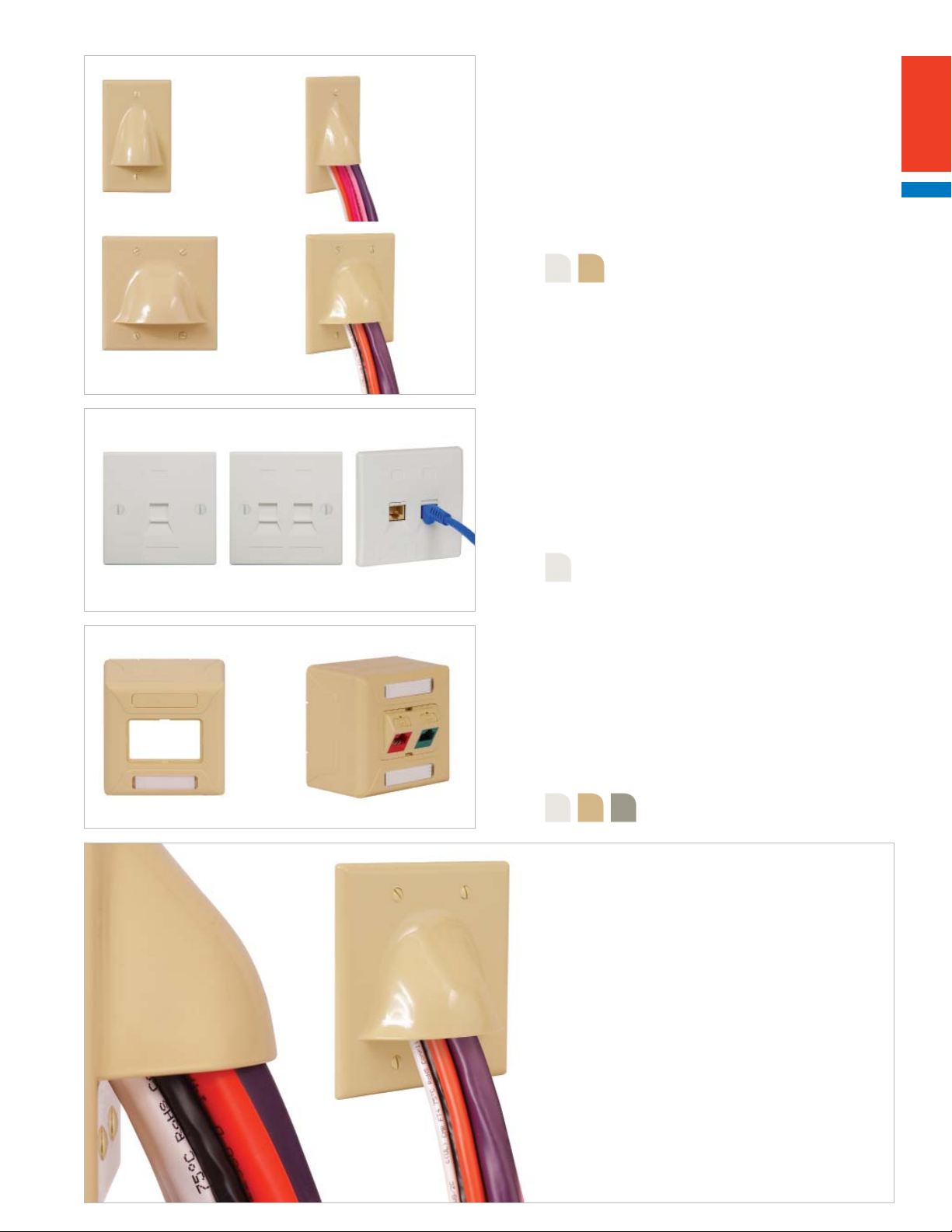
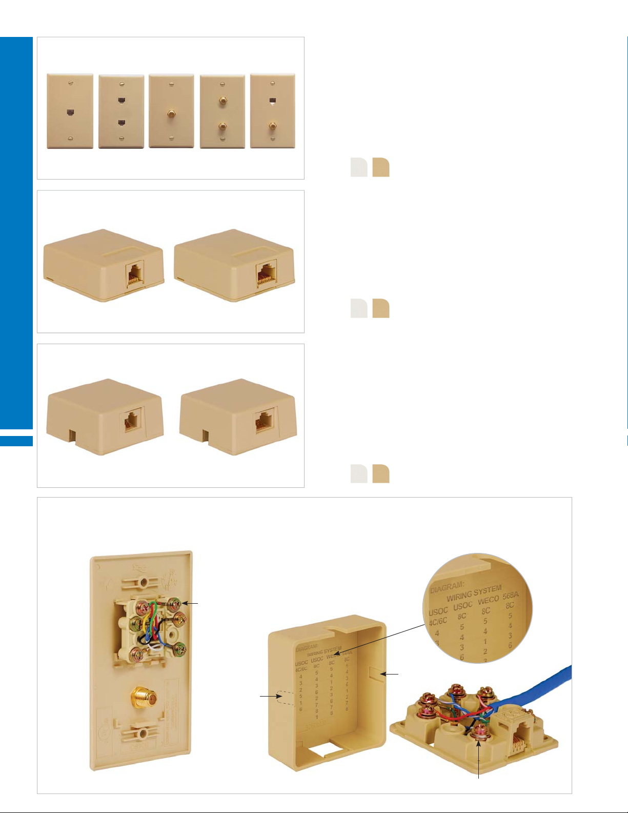
SCREW DOWN TERMINATION FEATURES
Wall plates, surface mount jacks and DécorexTM inserts are designed with deep slotted Phillips screw heads to provide a traditional way to terminate wires.
Wiring diagram is molded under the cover
Deep slotted and fl at Phillips screws will not slip
when using automatic screw drivers
24
Removable side knockouts
Double washers so wires will not unwind
888.ASK.4ICC | csr@icc.com | icc.com | MPS
Page 25
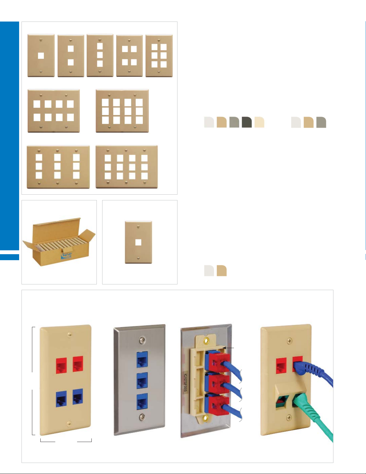
WORK AREA OUTLETS
A. B. C.
DÉCOREX INSERTS INTEGRATED WITH VOICE AND VIDEO
• Designed with rear Phillips screw down terminals
• Durable ABS plastic
PART NO. DESCRIPTION CARTON / CASE
A. IC630DI6xx¹ 6P6C 25 / 200
B. IC630DD6xx¹ 2 6P6C 50 / 400
C. IC630DVFxx¹ 6P6C and F-Type 25 / 200
Color (xx¹) = WH IV AL
TELEPHONE WALL PLATES INTEGRATED WITH VOICE
• Designed with standoffs to mount phones on walls and vertical surfaces
• Designed with rear Phillips screw down terminals
• Durable ABS plastic
PART NO. DESCRIPTION CARTON / CASE
IC630DB6xx¹ 6P6C, single gang 25 / 200
Color (xx¹) = WH IV
A. B.
Telephone Wall Plates
Designed with mounting standoffs
so phones can be hung securely
on the wall.
TELEPHONE WALL PLATES INTEGRATED WITH VOICE
• Designed with standoffs to mount phones on walls and vertical surfaces
• Designed with rear 110-Type IDC for fast termination
• Package includes 110 punch-down termination tool
PART NO. DESCRIPTION CARTON / CASE
A. IC630DA6SS 6P6C, single gang, stainless steel 25 / 200
B. IC630SS6xx¹ 6P6C, single gang, ABS plastic 25 / 200
Color (xx¹) = WH IV
Page
22 and 25
25
Page 26
WORK AREA OUTLETS FURNITURE FACEPLATES
CONFIGURABLE HIGH DENSITY NEMA MODULAR FURNITURE FACEPLATES
• Fits in offi ce furniture with NEMA size openings
HD modular connectors
• Faceplates are confi gurable with HD style connectors only
Port labeling areas
Station ID
PART NO. IC107FN4xx¹
WORK AREA OUTLETS
CONFIGURABLE HIGH DENSITY TIA MODULAR FURNITURE FACEPLATES
2.60" W
• Fits in offi ce furniture with TIA size openings
• Faceplates are confi gurable with HD style connectors only
1.83" H
0.19" D
Color (xx¹) = WH IV BK AL
HD modular connectors
GY
Port labeling areas
Station ID
PART NO. IC107FT4xx¹
CONFIGURABLE MODULAR FURNITURE FACEPLATES
• Fits in offi ce furniture with TIA size openings
• Faceplates are confi gurable with EZ
Port labeling areas
®
and HD style connectors
2.60" W
2.56" W
1.33" H
1.30" H
0.19" D
0.19" D
GY
Color (xx¹) = WH IV BK AL
EZ modular connectors
GY
26
PART NO. IC107FM3xx¹
CONFIGURABLE UNIVERSAL MODULAR FURNITURE FACEPLATES WITH ADJUSTABLE LOCKING TABS
• Two-piece design, faceplate and mounting box
• Faceplates are confi gurable with EZ
®
and HD style connectors
• Package includes wood screws for mounting
PART NO. IC108UF4xx¹
Station ID 1.76" D
888.ASK.4ICC | csr@icc.com | icc.com | MPS
Adjustable 2.0" to 3.5" W
Adjustable 0.875" to 2.375" H
2.34" to 3.50" W
0.82" to 1.93" H
Color (xx¹) = WH IV BK AL
GY
Color (xx¹) = WH IV BK AL
Page 27
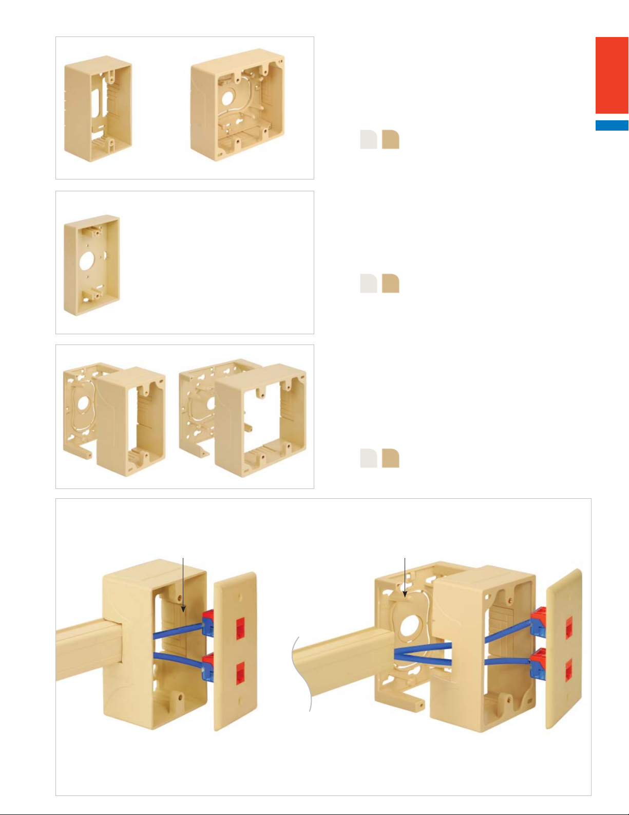
WORK AREA OUTLETS MOUNTING BOXES
A. B.
MOUNTING BOXES
• Durable ABS plastic
• Package includes adhesive strips and wood screws for mounting
• Package includes cable ties for cable management
PART NO. DESCRIPTION
A. IC107MRSxx¹ Single gang, 4.5" H x 2.75" W x 1.89" D
B. IC107MRDxx¹ Double gang, 4.5" H x 4.6" W x 1.89" D
Color (xx¹) = WH IV
LOW-PROFILE MOUNTING BOXES
• Works with wall plates and Décorex inserts with screw-down terminals only
• Durable ABS plastic
• Package includes wood screws for mounting
PART NO. DESCRIPTION
IC250MBSxx¹ Single gang, 4.5" H x 2.75" W x 0.93" D
Color (xx¹) = WH IV
JUNCTION BOXES
A. B.
• Two-piece design; mounting box and base
• Durable ABS plastic
• Package includes adhesive strips and wood screws for mounting
• Package includes cable ties for cable management
PART NO. DESCRIPTION
A. ICACSMBSxx¹ Single gang, 4.5" H x 2.75" W x 1.89" D
B. ICACSMBDxx¹ Double gang, 4.5" H x 4.6" W x 1.89" D
Color (xx¹) = WH IV
MOUNTING AND JUNCTION BOX FEATURES
Mounting and junction boxes fi t standard NEMA outlet boxes. They work with single and double gang faceplates. Designed with routing posts,
cable tie points and knockouts to work with raceway systems.
Routing postsKnockout
Mounting boxes: Cables need to be pulled
through the box prior to mounting.
Junction boxes: Bases and raceway can be
mounted prior to cable pulling.
27
Page 28
WORK AREA OUTLETS SURFACE MOUNT BOXES
A. B. C.
CLASSIC CONFIGURABLE SURFACE MOUNT BOXES
• Two-piece design; cover and base
• Durable ABS plastic
• Package includes adhesive strips and wood screws for mounting
PART NO. DESCRIPTION
A. IC107SB1xx¹ 1-Port
B. IC107SB2xx¹ 2-Ports
C. IC107SB4xx² 4-Ports
D. E.
WORK AREA OUTLETS
A.
D. IC107SB6xx² 6-Ports
E. IC107SBTxx² 12-Ports, 1 station ID, works with raceway and magnets
Color (xx¹) = WH IV GY BK Color (xx2) = WH IV BK
CLASSIC CONFIGURABLE SURFACE MOUNT BOX VALUEPACKS
• Packaged in a resealable box for easy storage
• Reduces packaging waste
• 25 pieces per box
PART NO. DESCRIPTION
A. IC107BC1xx¹ 1-Port, 25 pcs.
IC107BC2xx¹ 2-Ports, 25 pcs.
Color (xx¹) = WH IV
C. A.
ELITE™ CONFIGURABLE SURFACE MOUNT BOXES
• Two-piece design; cover and base
• Designed to work with raceway and magnets
• Durable ABS plastic
• Package includes adhesive strips and wood screws for mounting
• Package includes icons
PART NO. DESCRIPTION
B. D.
SURFACE MOUNT BOX FEATURES
Classic and EliteTM surface mount boxes are confi gurable with HD and EZ® style modular connectors.
Elite boxes and 12-Port classic box work with raceway
Magnets (optional) Cable tie anchor pointsRemovable cover
A. IC108SB1xx¹ 1-Port
B. IC108SB2xx¹ 2-Ports
C. IC108SB4xx¹ 4-Ports, includes cable ties
D. IC108SB6xx¹ 6-Ports, includes cable ties
Color (xx¹) = WH IV GY
28
Classic 2-Port box Classic 12-Port box Elite 4-Port box
888.ASK.4ICC | csr@icc.com | icc.com | MPS
Page 29
WORK AREA OUTLETS MOBILE PATCH BOXES
6-PORT CAT 6 AND CAT 5e MOBILE PATCH BOXES
A.
• Two-piece design; cover and base
• Designed with rear 110-Type IDC for fast termination
• 50 micro-inch gold plated contacts
• Exceeds TIA-568 CAT 6 and CAT 5e performance standards
• Package includes wood screws for mounting
• Package includes cable ties for cable management
• Durable ABS plastic
PART NO. DESCRIPTION
B.
A. ICMPPMB606 CAT 6, 8P8C, 6-Ports
B. ICMPPMB506 CAT 5e, 8P8C, 6-Ports
6-PORT CONFIGURABLE MOBILE PATCH BOX
• Two-piece design; cover and base
• Box is confi gurable with modular connectors
• Package includes wood screws for mounting
• Package includes cable ties for cable management
• Durable ABS plastic
PART NO. DESCRIPTION
IC107MB6BK 6-Ports blank
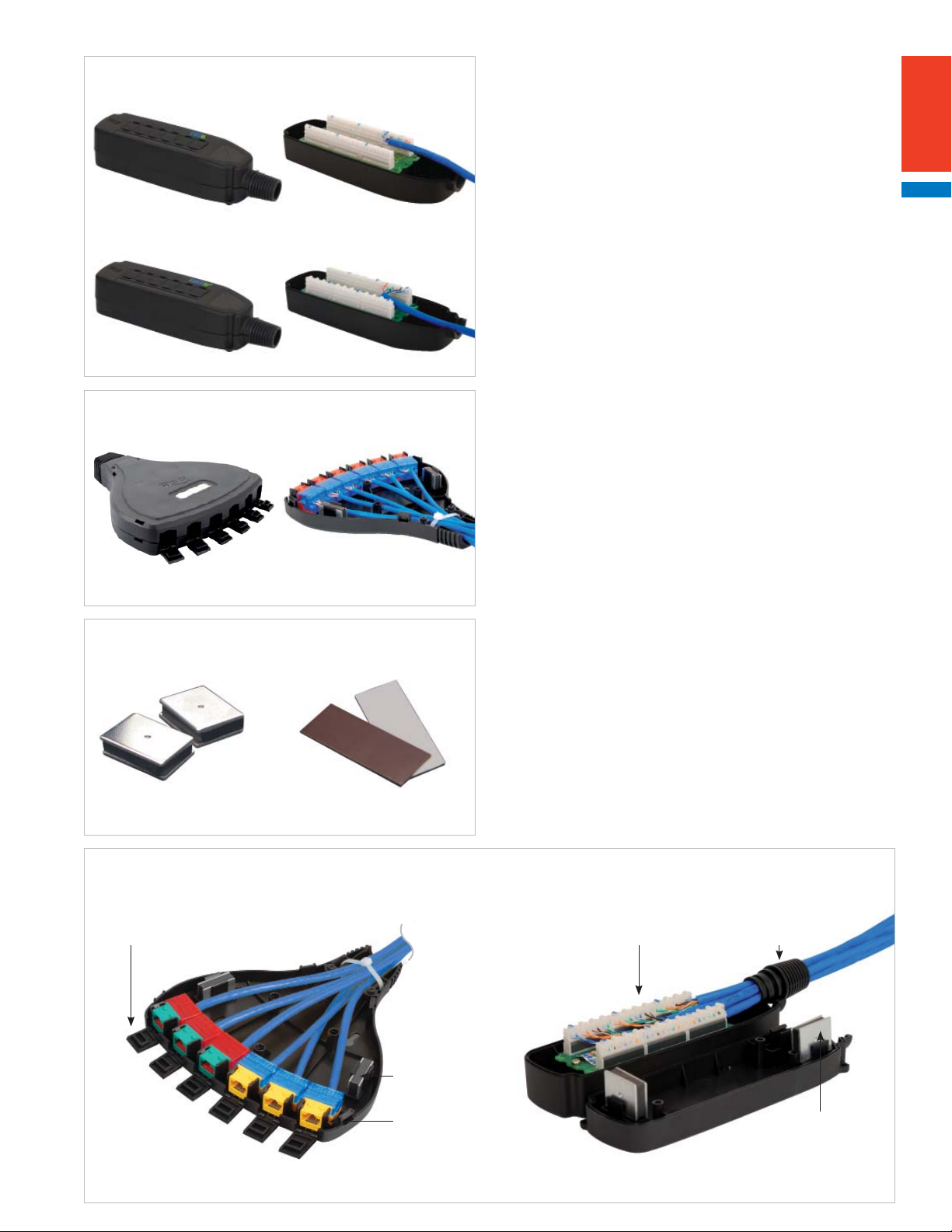
METAL AND ADHESIVE MAGNETS
A. B.
• To mount boxes on fl at metal surfaces
PART NO. DESCRIPTION
A. ICMAGBLOCK Metal magnet, 2 pcs.
• Works with boxes designed with magnet holders
B. IC317MTAPE Adhesive magnet, 2 pcs.
• Magnetic front with rear adhesive tape
• Works with all boxes
MOBILE PATCH BOX FEATURES
Mobile patch boxes allow connectivity in open environments where outlet is unavailable. Use for temporary workstations, POS terminals, warehouses,
industrial environment, tradeshows, retail showrooms and more.
Dust covers
Magnets (optional)
Universal T568A and T568B wiring Strain relief
Snap-in design
Confi gurable Integrated
Magnets (optional)
29
Page 30
WORK AREA OUTLETS ELITE FACEPLATES AND OUTLETS
FLAT AND ANGLED ELITE™ BEZELS
• Install bezels in Elite
TM
series faceplates, outlets and MUTOA boxes
• Package includes icons
PART NO.
DESCRIPTION
IC108BF1xx¹
1-Port, fl at
IC108BF2xx¹
2-Ports, fl at
WORK AREA OUTLETS
SINGLE AND DOUBLE GANG ELITE™ FACEPLATES WITH STATION ID
IC108BA1xx¹
1-Port, angled
IC108BA2xx¹
2-Ports, angled
Color (xx¹) = WH IV
IC108BFBxx¹
Blank, fl at
Color (xx¹) = WH IV
Confi gurable with
TM
bezels
Elite
PART NO.
DESCRIPTION
IC108F01xx¹
1-Bezel opening
IC108F02xx¹
2-Bezel openings
IC108FD4xx¹
4-Bezel openings
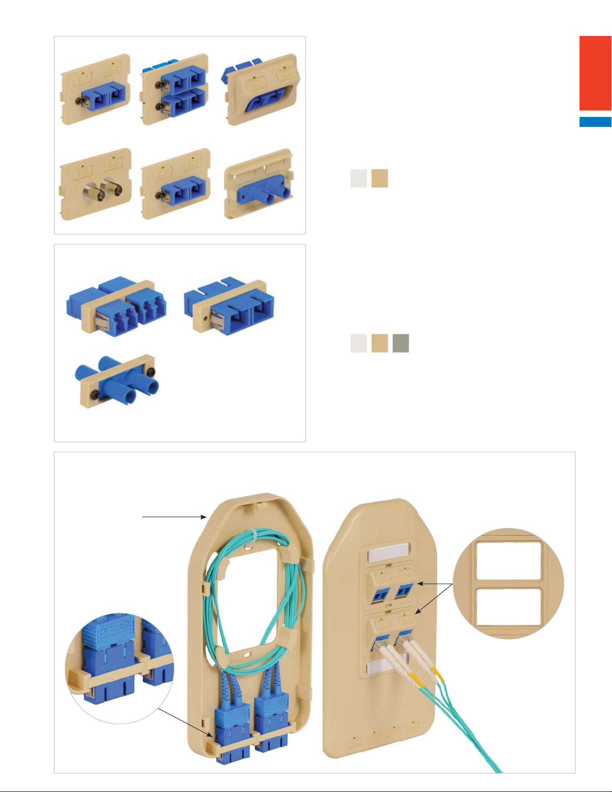
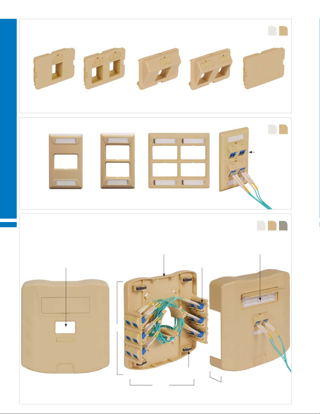
MULTI-USER TELECOMMUNICATIONS OUTLET ASSEMBLY (MUTOA) ELITE™ MULTIMEDIA BOXES
Package includes:
• Cover and base
• Cable ties for cable management
• Paper labels and clear view covers
• Adhesive strips and wood screws for mounting
1-Bezel opening
8.67" H
Knockouts on top and bottom work with raceway
6-Bezel openings
Color (xx¹) = WH IV GY
Circuit identifi cation label
30
PART NO. DESCRIPTION
IC108MMBxx¹ MUTOA multimedia box with 7 Elite bezel openings
888.ASK.4ICC | csr@icc.com | icc.com | MPS
Magnets (optional)
8.50" W
2.41" D
Page 31

WORK AREA OUTLETS ELITE FACEPLATES AND OUTLETS
SINGLE GANG ELITE™ MULTIMEDIA OUTLETS
Package includes:
• Cover and base
• Cable ties for cable management
• Paper labels and clear view covers
• Wood screws for mounting
2-Bezel openings
Color (xx¹) = WH IV GY
Confi gurable with EliteTM bezels
Fits single
gang outlet
7.50" H
1" D
PART NO. DESCRIPTION
IC108WBSxx¹ Single gang multimedia outlet with 2 Elite and 2 slim bezel openings
DOUBLE GANG ELITE™ MULTIMEDIA OUTLETS
Package includes:
4.45" W
• Cover and base
• Cable ties for cable management
• Paper labels and clear view covers
• Wood screws for mounting
4-Bezel openings
Fits double
gang outlet
7.50" H
2 slim bezel openings
Color (xx¹) = WH IV GY
6" W1" D
PART NO. DESCRIPTION
IC108WBDxx¹ Double gang multimedia outlet with 4 Elite and 3 slim bezel openings
3 slim bezel openings
31
Page 32

PATCH PANELS & CROSS-CONNECT
CAT 6A PATCH PANELS
CAT 6A 10G UNSHIELDED TWISTED PAIR (UTP) PATCH PANEL
• Permanent Link performance tested up to 7.3dB headroom at 500 MHz
• Panel comes with 24 CAT 6A UTP HD style black modular connectors
• 50 micro-inch gold plated contacts
• Fits standard 19” EIA rack mount widths
• Package includes cable management bar, cable ties and #12 rack screws
PART NO. DESCRIPTION
ICMPP246AU 24-Port CAT 6A UTP patch panel, 1 RMS*
PATCH PANELS & CROSS-CONNECT
PERMANENT LINK PERFORMANCE TEST
100
80
60
40
20
0
0500
Installed with ICC premise cable and tested per TIA
Permanent Link specifi cation
NEXTdB
Signal transmission
Headroom
TIA standard limit
Frequency (MHz)
CAT 6A 10G FOILED TWISTED PAIR (FTP) PATCH PANEL
• Permanent Link performance tested up to 2.8dB headroom at 500 MHz
• FTP provides excellent protection against EMI/RFI interferences
• Panel comes with 24 CAT 6A FTP HD style modular connectors
• 50 micro-inch gold plated contacts
• Pre-installed grounding studs
• Fits standard 19” EIA rack mount widths
• Package includes cable management bar, cable ties and #12 rack screws
PART NO. DESCRIPTION
ICMPP246AS 24-Port CAT 6A FTP patch panel, 1 RMS*
PERMANENT LINK PERFORMANCE TEST
100
80
60
40
20
0
0500
Installed with ICC premise cable and tested per TIA
Permanent Link specifi cation
NEXTdB
TIA standard limit
Frequency (MHz)
32
*1 RMS (rack mount space) = 1.75" H
888.ASK.4ICC | csr@icc.com | icc.com | CXS
Page 33

PATCH PANELS & CROSS-CONNECT PATCH PANEL FEATURES
HORIZONTAL PATCH PANEL FEATURES
• Exceeds TIA-568 performance standards
• Built-in PCB technology for maximum signal quality
• 50 micro-inch gold plated contacts
Color wiring diagram makes termination fast and easy
VERTICAL ZERO-U PATCH PANEL FEATURES
• Designed to mount on walls and distribution racks, uses no rack space
• Exceeds TIA-568 performance standards
4-Pair punch-down tool
Nylon cable ties
Retention caps
Purchased separately
• Built-in PCB technology for maximum signal quality
• 50 micro-inch gold plated contacts
Rear 110-Type IDC
FRONT ACCESS ZERO-U PATCH PANEL FEATURES
• Designed to mount on walls and distribution racks, uses no rack space
• Exceeds TIA-568 performance standards
• Front access 110-Type IDC terminations
• 50 micro-inch gold plated contacts
• Designed for wall mount
• Removable cover
33
Page 34

PATCH PANELS & CROSS-CONNECT
CAT 6 AND CAT 5e PATCH PANELS
CAT 6 AND CAT 5e 12-PORT VERTICAL ZERO-U PATCH PANELS
• Two-piece design; patch panel with 89D mounting bracket
• Designed to mount on walls and distribution racks, uses no rack space
• 10” H x 3.30” W x 2.40” D
• Package includes cable ties for cable management
PART NO. DESCRIPTION CARTO N
ICMPP12V60 CAT 6, 12-Ports, 8P8C 25
ICMPP12V5E CAT 5e, 12-Ports, 8P8C 25
CAT 6 AND CAT 5e 24-PORT PATCH PANEL
• Fits standard 19” EIA rack mount widths
• Package includes cable ties and #12 rack screws
PART NO. DESCRIPTION CARTO N
ICMPP02460 CAT 6, 24-Ports, 8P8C, 1 RMS* 16
ICMPP0245E CAT 5e, 24-Ports, 8P8C, 1 RMS* 16
PATCH PANELS & CROSS-CONNECT
CAT 6 AND CAT 5e 48-PORT PATCH PANEL
• Fits standard 19” EIA rack mount widths
• Package includes cable ties and #12 rack screws
PART NO. DESCRIPTION CARTO N
ICMPP04860 CAT 6, 48-Ports, 8P8C, 2 RMS* 10
ICMPP0485E CAT 5e, 48-Ports, 8P8C, 2 RMS* 10
CAT 6 AND CAT 5e 12-PORT FRONT ACCESS ZERO-U PATCH PANELS
• Two-piece design; patch panel with removable cover
• Front access 110-Type IDC terminations
• Designed to mount on walls and distribution racks, uses no rack space
PART NO. DESCRIPTION CARTO N
ICMPP12F6E CAT 6, 12-Ports, 8P8C, front access 10
ICMPP12F5E CAT 5e, 12-Ports, 8P8C, front access 10
*1 RMS (rack mount space) = 1.75" H
34
DUST COVER
• Works with CAT 6A, CAT 6, CAT 5e and voice modular
connectors and patch panels
• Snaps on the port opening to prevent dust from entering
PART NO. DESCRIPTION
ICACSDCICL Dust cover, 10 pcs.
ICACSDCVCL Dust cover, 100 pcs.
Color = Clear
888.ASK.4ICC | csr@icc.com | icc.com | CXS
VALUEPACK
Page 35

PATCH PANELS & CROSS-CONNECT VOICE PATCH PANELS
VOICE 12-PORT USOC VERTICAL ZERO-U PATCH PANEL
• Two-piece design; patch panel with 89D mounting bracket
• Designed to mount on walls and distribution racks, uses no rack space
• 10” H x 3.30” W x 2.40” D
• Package includes cable ties for cable management
PART NO. DESCRIPTION CARTO N
ICMPP012U6 12-Ports, 6P6C, USOC wiring 25
VOICE 24-PORT USOC PATCH PANEL
• Fits standard 19” EIA rack mount widths
• Package includes cable ties and #12 rack screws
PART NO. DESCRIPTION CARTO N
ICMPP024U6 24-Ports, 6P6C, USOC wiring, 1 RMS* 15
VOICE 48-PORT USOC PATCH PANEL
• Fits standard 19” EIA rack mount widths
• Package includes cable ties and #12 rack screws
PART NO. DESCRIPTION CARTO N
ICMPP048U6 48-Ports, 6P6C, USOC wiring, 2 RMS* 10
PATCH PANEL CABLE MANAGEMENT BAR
• Mount on rear of 19" rack mount patch panels
• Works with CAT 6, CAT 5e and voice patch panels
• Designed to support terminated cable
• Durable ABS plastic
PART NO. DESCRIPTION CARTO N
ICMPP25CMB Cable management bar 40
*1 RMS (rack mount space) = 1.75" H
PATCH PANEL COLOR ICONS
• Apply to patch panels for system administration
• Icons are molded with text identifi cation
• 12 icons per tree
PART NO. DESCRIPTION
ICMPPSCIxx¹ 6 voice and 6 data icons
ICMPPICDxx¹ 12 data icons
ICMPPICVxx¹ 12 voice icons
Color (xx¹) = WH IV BL OR RD YL GY GN PR
35
Page 36

PATCH PANELS & CROSS-CONNECT
FEED-THROUGH PATCH PANELS
48-PORT HIGH DENSITY PATCH PANEL WITH CAT 6 AND CAT 5e
FEED-THROUGH MODULAR COUPLERS
• Fits standard 19” EIA rack mount widths
• 48 modular couplers pre-installed
• Package includes #12 rack screws
PART NO. DESCRIPTION
ICMPP48C61 48-Ports, CAT 6, 8P8C,1 RMS*
ICMPP48C51 48-Ports, CAT 5e, 8P8C, 1 RMS*
HIGH DENSITY PATCH PANELS WITH CAT 6 FEED-THROUGH
MODULAR COUPLERS
• Fits standard 19” EIA rack mount widths
• 24 modular couplers pre-installed
• Package includes #12 rack screws
PART NO. DESCRIPTION
ICMPP24CP6 24-Ports, CAT 6, 8P8C,1 RMS*
ICMPP48CP6 48-Ports, CAT 6, 8P8C, 2 RMS*
PATCH PANELS & CROSS-CONNECT
HIGH DENSITY PATCH PANELS WITH CAT 5e FEED-THROUGH
MODULAR COUPLERS
• Fits standard 19” EIA rack mount widths
• 24 modular couplers pre-installed
• Package includes #12 rack screws
PART NO. DESCRIPTION
ICMPP24CP5 24-Ports, CAT 5e, 8P8C,1 RMS*
ICMPP48CP5 48-Ports, CAT 5e, 8P8C, 2 RMS*
FEED-THROUGH PATCH PANEL FEATURES
• CAT 6 or CAT 5e modular couplers pre-installed
• 50 micro-inch gold plated contacts
36
Connect patch cords on both ends
888.ASK.4ICC | csr@icc.com | icc.com | CXS
No assembly and no termination is required
Page 37

PATCH PANELS & CROSS-CONNECT BLANK PATCH PANELS
CONFIGURABLE HIGH DENSITY BLANK PATCH PANEL
• Panel is confi gurable with HD style modular connectors
PART NO. DESCRIPTION
IC107BP481 48-Ports blank, 1 RMS*
CONFIGURABLE CAT 6A UTP BLANK PATCH PANEL
• Panel is confi gurable with CAT 6A UTP modular connectors
PART NO. DESCRIPTION
IC107PPU6A 24-Ports blank, 1 RMS*
CONFIGURABLE CAT 6A FTP BLANK PATCH PANEL
• Panel is confi gurable with CAT 6A FTP modular connectors
PART NO. DESCRIPTION
IC107PPS6A 24-Ports blank, 1 RMS*
CONFIGURABLE HIGH DENSITY BLANK PATCH PANEL
• Panel is confi gurable with HD style modular connectors
PART NO. DESCRIPTION
IC107BP241 24-Ports blank, 1 RMS*
IC107BP482 48-Ports blank, 2 RMS*
CONFIGURABLE BLANK PATCH PANEL
• Panel is confi gurable with EZ style modular connectors
PART NO. DESCRIPTION
IC107BE241 24-Ports blank, 1 RMS*
*1 RMS (rack mount space) = 1.75" H
37
Page 38

PATCH PANELS & CROSS-CONNECT
VERTICAL BLANK PATCH PANELS
CONFIGURABLE HIGH DENSITY WALL MOUNT VERTICAL ZERO-U
BLANK PATCH PANEL
• Two-piece design; patch panel with 89U mounting bracket
• Panel is confi gurable with HD style modular connectors only
• 10” H x 3.30” W x 2.80” D
PART NO. DESCRIPTION CARTO N
IC107BP12V 12-Ports blank 30
CONFIGURABLE WALL MOUNT VERTICAL ZERO-U BLANK PATCH PANEL
• Two-piece design; patch panel with 89U mounting bracket
• Panel is confi gurable with EZ
®
style modular connectors
• 10” H x 3.30” W x 2.80” D
PART NO. DESCRIPTION CARTO N
IC107BP8VB 8-Ports blank 30
PATCH PANELS & CROSS-CONNECT
VERTICAL ZERO-U BLANK PATCH PANEL FEATURES
• Vertical patch panels are designed to mount on walls and distribution racks, uses no rack space
• They provide a fl exible solution suitable as a Consolidation Point in the Work Area
• Mounting bracket acts as a channel for routing cable behind the termination
12-Port HD style
Front view Rear view
Front view Rear view
8-Port EZ style
38
888.ASK.4ICC | csr@icc.com | icc.com | CXS
Page 39

PATCH PANELS & CROSS-CONNECT TELCO PATCH PANELS
VOICE 8P2C PATCH PANELS WITH REAR TELCO CONNECTORS
• Fits standard 19” EIA rack mount widths
• Package includes cable ties and #12 rack screws
PART NO. DESCRIPTION CARTO N
ICMPP24T2C 24-Ports, active pins: 4 and 5, 1 RMS* 15
ICMPP48T2C 48-Ports, active pins: 4 and 5, 2 RMS* 10
• Male 50-Pin Telco connector(s) on the rear
ICMPP24TF2 24-Ports, active pins: 4 and 5, 1 RMS*
ICMPP48TF2 48-Ports, active pins: 4 and 5, 2 RMS* 10
15
• Female 50-Pin Telco connector(s) on the rear
VOICE 8P4C PATCH PANELS WITH REAR TELCO CONNECTORS
• Fits standard 19” EIA rack mount widths
• Package includes cable ties and #12 rack screws
PART NO. DESCRIPTION CARTO N
ICMPP24T4C 24-Ports, active pins: 3/4 and 5/6, 1 RMS* 15
ICMPP48T4C 48-Ports, active pins: 3/4 and 5/6, 2 RMS* 15
• Male 50-Pin Telco connector(s) on the rear
ICMPP24TF4 24-Ports, active pins: 3/4 and 5/6, 1 RMS*
ICMPP48TF4 48-Ports, active pins: 3/4 and 5/6, 2 RMS* 15
15
• Female 50-Pin Telco connector(s) on the rear
VOICE 6P2C PATCH PANELS WITH REAR TELCO CONNECTORS
• Fits standard 19” EIA rack mount widths
• Package includes cable ties and #12 rack screws
PART NO. DESCRIPTION CARTO N
ICMPP024T2 24-Ports, active pins: 3 and 4, 1 RMS* 15
ICMPP048T2 48-Ports, active pins: 3 and 4, 2 RMS* 10
• Male 50-Pin Telco connector(s) on the rear
ICMPPTF242 24-Ports, active pins: 3 and 4, 1 RMS*
ICMPPTF482 48-Ports, active pins: 3 and 4, 2 RMS* 10
• Female 50-Pin Telco connector(s) on the rear
VOICE 6P4C PATCH PANELS WITH REAR TELCO CONNECTORS
• Fits standard 19” EIA rack mount widths
• Package includes cable ties and #12 rack screws
PART NO. DESCRIPTION CARTO N
ICMPP024T4 24-Ports, active pins: 3/4 and 2/5, 1 RMS* 15
ICMPP048T4 48-Ports, active pins: 3/4 and 2/5, 2 RMS* 10
• Male 50-Pin Telco connector(s) on the rear
ICMPPTF244 24-Ports, active pins: 3/4 and 2/5, 1 RMS*
ICMPPTF484 48-Ports, active pins: 3/4 and 2/5, 2 RMS* 10
• Female 50-Pin Telco connector(s) on the rear
*1 RMS (rack mount space) = 1.75" H
Male Telco Connector Female Telco Connector
15
15
39
Page 40

PATCH PANELS & CROSS-CONNECT
110 WIRING
CAT 6 110 WIRING BLOCK KIT
• 96-Pair base with feet
• Package includes 24 4-Pair 110 connecting blocks
PART NO. DESCRIPTION CARTO N
IC110WK966 96-Pair wiring block kit 10
CAT 5e 110 WIRING BLOCK KITS
PART NO. DESCRIPTION CARTO N
IC110W1004 100-Pair wiring block kit 10
• 100-Pair base with feet
• Package includes 20 4-Pair and 4 5-Pair 110 connecting blocks
PATCH PANELS & CROSS-CONNECT
IC110W3004 300-Pair wiring block kit
• 300-Pair base with feet
• Package includes 60 4-Pair and 12 5-Pair 110 connecting blocks
110 WIRING BLOCKS WITH FEET
PART NO. DESCRIPTION CARTO N
IC110WF100 100-Pair wiring block 10
IC110WF300 300-Pair wiring block 5
110 WIRING BLOCKS WITHOUT FEET
PART NO. DESCRIPTION CARTO N
IC110NF100 100-Pair wiring block 40
IC110NF300 300-Pair wiring block 10
5
40
A.
B.
110 CABLE MANAGEMENT BLOCKS
• Works with 110 wiring blocks
• Helps organize cable
PART NO. DESCRIPTION CARTO N
A. IC110CMBWF Block with feet 25
B. IC110CMBNF Block without feet 50
888.ASK.4ICC | csr@icc.com | icc.com | CXS
Page 41

PATCH PANELS & CROSS-CONNECT 110 WIRING
CAT 5e 110 HINGED WIRING BLOCK KIT
• 100-Pair hinged base
• Hinge design allows access to the rear of the block
• Package includes 20 4-Pair and 4 5-Pair 110 connecting blocks
PART NO. DESCRIPTION CARTO N
IC110H1004 100-Pair hinged wiring block kit 10
110 HINGED WIRING BLOCK
• 100-Pair hinged base
• Hinge design allows access to the rear of the block
PART NO. DESCRIPTION CARTO N
IC110WH100 100-Pair hinged wiring block 10
110 HINGED CABLE MANAGEMENT BLOCK
• Works with 110 hinged wiring blocks
• Hinge design allows access to the rear of the cable channel
• Helps organize cable
PART NO. DESCRIPTION CARTO N
IC110WHCMS Hinged cable management block 25
110 WIRING SYSTEM FEATURES
• High performance solution for phone and data communications
• Ideal in a Telco Room, Main Distribution Frame, Intermediate
Distribution Frame and Consolidation Point
110 WIRING LABEL HOLDERS
• Use with 110 wiring blocks
• Holds and protects labels
PART NO. DESCRIPTION
IC110LHLDR Label holders, 6 pcs.
41
Page 42

PATCH PANELS & CROSS-CONNECT
A.
B.
110 WIRING
CAT 6 RACK MOUNT 110 WIRING BLOCK PANEL KIT
• 96-Pair base with steel panel
• Fits standard 19” EIA rack mount widths
• Package includes 24 4-Pair 110 connecting blocks
• Package includes labels, label holders and #12 rack screws
PART NO. DESCRIPTION CARTO N
IC110PRK61 96-Pair wiring block kit, 1 RMS* 15
RACK MOUNT 110 WIRING BLOCK PANELS
• Works with 3-Pair, 4-Pair and 5-Pair connecting blocks
• Fits standard 19” EIA rack mount widths
• Package includes labels, label holders and #12 rack screws
PART NO. DESCRIPTION CARTO N
A. IC110RM100 100-Pair wiring block, 1 RMS* 15
• 100-Pair base with steel panel
B. IC110RM200 300-Pair wiring block, 2 RMS*
10
• 300-Pair base with steel panel
PATCH PANELS & CROSS-CONNECT
RACK MOUNT 110 CABLE MANAGEMENT PANEL
• Plastic clips with steel panel
• Fits standard 19” EIA rack mount widths
• Helps organize cable
PART NO. DESCRIPTION CARTO N
IC110RMCMB 110 cable management panel, 1 RMS* 15
*1 RMS (rack mount space) = 1.75" H
Connect 110 Systems with 110 Patch Cords
42
110 patch cords
Page 74
888.ASK.4ICC | csr@icc.com | icc.com | CXS
Page 43

PATCH PANELS & CROSS-CONNECT 110 WIRING
A. B.
110 CONNECTING BLOCKS
• Works with 110 wiring blocks
• Supports Category 5e data
• Terminate with 22~26 AWG solid or stranded wires
• Color coded for easy termination
PART NO. DESCRIPTION CARTO N
A. IC110CB4PR 4-Pair, 10 pcs. 300
C. D.
B. IC110CB5PR 5-Pair, 10 pcs. 320
C. IC110CB4PC 4-Pair, 100 pcs. VALUEPACK
D. IC110CB5PC 5-Pair, 100 pcs. VALUEPACK
110 RETENTION CAP
• Secures and protects terminated wires
• Works with 110 connecting blocks and patch panels
• 50 pieces per bag
PART NO. DESCRIPTION CARTO N
IC110TC450 4 Conductor, 2-Pair, 110 retention cap, 50 pcs. 400
A. B.
CABLE MANAGEMENT SPOOLS
• Wall mounts to help retain and guide cable
• 10 pieces per bag
PART NO. DESCRIPTION CARTO N
A. ICACSWDS20 Spool with built-in wood screw, 10 pcs. 30
B. ICACSWDS10 Spool without screw, 10 pcs. 30
A. B.
110 PATCH PLUGS
PART NO. DESCRIPTION
A. ICMP1101PR Terminates 1-Pair of CAT 5e cable
B. ICMP1102PR Terminates 2-Pairs of CAT 5e cable
C. ICMP1103PR Terminates 3-Pairs of CAT 5e cable
D. ICMP1104PR Terminates 4-Pairs of CAT 6 cable
• Terminate with solid or stranded UTP cable
C. D.
Termination tools
Page 107
43
Page 44

PATCH PANELS & CROSS-CONNECT
A. B. C. D.
B. A.
66 WIRING
66 WIRING BLOCK, 50 PAIR
• Wall mountable
• Made of high impact fl ame retardant material UL 94V-0
PART NO. DESCRIPTION
A. IC066NB050 66 wiring block
MOUNTING BRACKETS
• Snaps on the rear of 66 wiring blocks
PART NO. DESCRIPTION
B. ICMB89B0WH 89B bracket, open rear, 10” H x 3.30” W x 1.90” D
C. ICMB89D0WH 89D bracket, open front, 10” H x 3.30” W x 1.90” D
D. ICMB89U0WH 89U bracket, open front, 10” H x 3.30” W x 2.35” D
66 WIRING BLOCK AND MOUNTING BRACKET VALUEPACKS
• Packaged in a resealable box for easy storage
• Reduces packaging waste
• 25 pieces per box
PART NO. DESCRIPTION
A. IC066NBC50 66 wiring block, 25 pcs.
B. ICMB89BCWH 89B mounting bracket, 25 pcs.
PATCH PANELS & CROSS-CONNECT
66 WIRING BLOCK SYSTEM
89B mounting bracket
C. A. B.
66 WIRING BLOCK COVER, LABELING STRIPS AND BRIDGING CLIPS
PART NO. DESCRIPTION
A. IC066CV050 Wiring block cover
• Protects terminated wires from dust and debris
B. IC066LS050 Labeling strips, 10 pcs.
• Use a standard labeler or pen
C. IC066BRCLP Bridging clips, 100 pcs.
• Electrically interconnect adjacent terminals within the same row
Labeling strips
44
Terminals are designed for repeated termination
Terminate with solid insulated or stripped
cable (22~26 AWG)
888.ASK.4ICC | csr@icc.com | icc.com | CXS
Bridging clips electrically interconnect
adjacent terminals within the same row
Page 45

PATCH PANELS & CROSS-CONNECT PRE-WIRED 66 WIRING
66 WIRING BLOCK PRE-WIRED WITH DATA PORTS
• Pre-wired data ports
• Integrated with 89D mounting bracket for wall mounting
• 10” H x 3.30” W x 3.00” D
PART NO. DESCRIPTION CARTO N
IC06628P8C 12-Ports, 8P8C 25
66 WIRING BLOCKS PRE-WIRED WITH VOICE PORTS
A. B.
• Pre-wired voice ports
• Integrated with 89D mounting bracket for wall mounting
• 10” H x 3.30” W x 3.00” D
PART NO. DESCRIPTION CARTO N
A. IC06686P6C 8-Ports, 6P6C 25
B. IC06626P4C 12-Ports, 6P4C 25
A. B.
66 WIRING BLOCKS PRE-WIRED WITH TELCO CONNECTORS
• Pre-wired with 1 or 2 female Telco connectors (25/50-Pair)
• Integrated with 89D mounting bracket for wall mounting
• 10” H x 3.30” W x 3.00” D
PART NO. DESCRIPTION CARTO N
A. IC066SFT25 Pre-wired with 1 25-pair female Telco connector 25
B. IC066DFT50 Pre-wired with 2 25-pair female Telco connectors 25
66 WIRING BLOCK PRE-WIRED WITH MODULAR CONNECTORS 66 WIRING BLOCK PRE-WIRED WITH TELCO CONNECTORS
Telco cable
Security strap
Hinged cover
Works with color icons
45
Page 46

PREMISE CABLES
15
YEAR
12
YEAR
3
YEAR
WARRANTY
LIFE
Permanent
Work Area (WA)
Horizontal Cabling
PREMISE CABLES
One Vendor, No Compatibility Issue
Premise cables and connectivity outlets are fi ne tuned to work together as End-to-End solutions. CAT 6
Permanent Link solution including modular connectors, patch panels and premise cables stack up to
7.6dB NEXT headroom when installed and tested per TIA specifi cation. We also work with Elite InstallersTM to
offer warranty programs that are simple and effective. Using End-to-End solutions, Elite Installers can offer
a 15 Year Performance Warranty without certifi cation. Better yet, Certifi ed Elite Installers can verify the site
and offer a Lifetime Performance Warranty.
Choosing the Right Cabling
Choose different category-rated cables to support any installation requirement. Premise cables exceed
TIA and IEEE standards and are backwards compatible with lower category-rated products.
TIA-568-C.2 Standards Frequency Applications Distance Maximum Pair Untwist
500 MHz
250 MHz
100 MHz 10/100 Base-T/1000 Base-T/ Phone 100 m. (328 ft.) 13 mm. (0.5 in.)
10/100/1000 Base-T/10 GbE, Digital Video,
IEEE 802.3at for PoE Plus
10/100/1000 Base-T, Digital Video, Phone,
IEEE 802.3at for PoE Plus
100 m. (328 ft.) 13 mm. (0.5 in.)
100 m. (328 ft.) 13 mm. (0.5 in.)
Protecting the Installation
• 15 Year Performance Limited WarrantyTM for Elite Installers: no certifi cation required
• Lifetime Performance Limited WarrantyTM for Certifi ed Elite Installers for verifi ed sites
• Go online to icc.com/warranty for complete terms and conditions
46
++=
Page 48Page 34Page 5
888.ASK.4ICC | csr@icc.com | icc.com | CAB
LIFE
WARRANTY
or
15
YEAR
TM
TM
Page 47

PREMISE CABLES
Link
Telecom Room (TR)
UTP vs. FTP
• Use Unshielded Twisted Pair (UTP) cable in low Electromagnetic
Interference (EMI) environments. UTP cable is more cost
effective compared to FTP since it does not require the
manufacturing cost of the shielding in FTP cable.
Foiled shielding
• Use Foiled Twisted Pair (FTP) cable in environments with high
Electromagnetic Interference (EMI) or Radio Frequency
Interference (RFI).
CMR vs. CMP
• Use Riser Rated Cable in vertical settings, such as cable runs
between fl oors through cable risers. These spaces cannot
be used for environmental air. The cable must self-extinguish
to prevent the fl ame from traveling up the cable.
• Use Plenum Rated Cable in spaces like raised fl ooring systems
and air handling ducts. Plenum cable must self-extinguish
and not reignite. They produce less smoke than traditional
PVC cable.
Premium Quality
• With stringent quality control procedures, premise cables
have been inspected and tested to comply with the strict
FCC®, TIA® and UL® standards.
• Premise cables are Restriction of Hazardous Substance (RoHS)
compliant to protect the environment.
47
Page 48

PREMISE CABLES
CAT 6A UTP 650 MHz 10G PREMISE CABLES
• 4-Pair, 23 AWG, UTP, solid copper cable
• Designed with an X separator
• 0.34" outer diameter
• Packaged on a reel; 13.0" H x 17.3" W
• 1000 feet per reel (305 meters)
GRAPH EXPLANATION: The graphs shown below display channel-rated performance tests of structured
cabling systems, modular connectors, patch panels and patch cords installed with premise cable.
NEXTdB
100
80
60
40
PREMISE CABLES
PART NO. DESCRIPTION PALLET
ICCABP6Axx¹ CAT 6A UTP cable, CMP (Plenum) 15
ICCABR6Axx¹ CAT 6A UTP cable, CMR (Riser) 15
Color (xx¹) = BL WH
CAT 6A FTP 650 MHz 10G PREMISE CABLES
• 4-Pair, 23 AWG, FTP, solid copper cable
• Shielded jacket protects from EMI and RFI noise
• Designed with an X separator
• 0.34" outer diameter
• Packaged on a reel; 13.0" H x 17.3" W
• 1000 feet per reel (305 meters)
PART NO. DESCRIPTION PALLET
ICCABP6Fxx¹ CAT 6A FTP cable, CMP (Plenum) 15
ICCABR6Fxx¹ CAT 6A FTP cable, CMR (Riser) 15
Color (xx¹) = BL
20
TIA standard limit
0
0500
Frequency (MHz)
Tested per TIA Channel Link specifi cation
NEXTdB
100
Signal transmission
80
60
40
TIA standard limit
Headroom
20
0
0500
Frequency (MHz)
Tested per TIA Channel Link specifi cation
48
CAT 6e UTP 600 MHz PREMISE CABLES
• 4-Pair, 23 AWG, UTP, solid copper cable
• Designed with an X separator
• 0.234" outer diameter
• Packaged in an EZ pull box; 15.55” H x 9.60” W x 15.75” D
• 1000 feet per box (305 meters)
PART NO. DESCRIPTION PALLET
ICCABP6Exx¹ CAT 6e UTP cable, CMP (Plenum) 36
ICCABR6Exx¹ CAT 6e UTP cable, CMR (Riser) 30
Color (xx¹) = BL WH GY YL GN
888.ASK.4ICC | csr@icc.com | icc.com | CAB
NEXTdB
100
80
60
40
TIA standard limit
20
0
0250
Frequency (MHz)
Tested per TIA Channel Link specifi cation
Page 49

PREMISE CABLES
CAT 6A UTP 650 MHz 10G PREMISE CABLE PERFORMANCE CHART
CHART EXPLANATION: The charts below show frequency and electrical performance values for reference only. Actual compliance testing is
based on swept frequency measurements. The specifi cation values are based on TIA-568 standard and are expressed in dB per 100M (328 Ft.).
FREQUENCY
(MHz)
ATTENUATION
(max)
RETURN LOSS
(min)
NEXT
(min)
PS NEXT
(min)
ACR
(min)
PS ACR
(min)
ACRF
(min)
PS ACRF
(min)
CAT 6A FTP 650 MHz 10G PREMISE CABLE PERFORMANCE CHART
FREQUENCY
(MHz)
ATTENUATION
(max)
RETURN LOSS
(min)
NEXT
(min)
PS NEXT
(min)
ACR
(min)
PS ACR
(min)
ACRF
(min)
PS ACRF
(min)
1 10 16 62.5 100 200 250 350 500 600 650
2.1 5.9 7.5 15.0 19.1 27.6 31.1 37.2 45.3 50.1 52.3
20.0 27.0 27.0 23.5 22.1 20.0 19.3 18.3 17.5 16.9 16.7
78.3 63.3 60.2 51.4 48.3 43.8 42.3 40.1 37.8 36.6 36.1
76.3 61.3 58.2 49.4 46.3 41.8 40.3 38.1 35.8 34.6 34.1
71.8 51.8 47.7 35.9 31.8 25.8 23.8 20.9 17.8 - -
68.8 48.8 44.7 32.9 28.8 22.8 20.8 17.9 14.8 - -
67.0 67.0 67.0 65.6 62.5 58.0 56.5 54.3 52.0 - -
67.0 58.2 54.1 42.3 38.2 32.2 30.2 27.3 24.2 - -
CAT 6e UTP 600 MHz PREMISE CABLE PERFORMANCE CHART
FREQUENCY
(MHz)
ATTENUATION
(max)
RETURN LOSS
(min)
NEXT
(min)
PS NEXT
(min)
ACR
(min)
PS ACR
(min)
ACRF
(min)
PS ACRF
(min)
1 10 16 62.5 100 200 250 350 500 600
2.0 5.9 7.4 14.9 19.1 27.7 31.2 37.5 45.8 50.7
21.0 25.5 26.0 26.0 22.5 19.8 19.0 17.8 16.2 15.7
82.3 67.3 64.2 55.4 52.3 47.8 46.3 45.7 44.8 44.2
80.3 65.3 62.2 53.4 50.3 45.8 44.3 43.7 42.8 42.2
80.3 61.4 56.8 40.4 33.2 20.1 15.1 8.2 0.0 -
78.3 59.4 54.8 38.4 31.2 18.1 13.1 6.2 - -
73.8 53.8 49.7 37.9 33.9 27.8 25.8 22.9 19.8 18.2
71.8 51.8 47.7 35.9 31.8 25.8 23.8 20.9 17.8 16.2
49
Page 50

PREMISE CABLES
CAT 6 UTP 500 MHz PREMISE CABLES, PLENUM
• 4-Pair, 23 AWG, UTP, solid copper cable
• 0.200" outer diameter
• Packaged in an EZ pull box; 15.50” H x 10.25” W x 15.50” D
• 1000 feet per box (305 meters)
GRAPH EXPLANATION: The graphs shown below display channel-rated performance tests of structured
cabling systems, modular connectors, patch panels and patch cords installed with premise cable.
NEXTdB
100
Signal transmission
80
60
PREMISE CABLES
PART NO. DESCRIPTION PALLET
ICCABP6Vxx¹ CAT 6 UTP cable, CMP (Plenum) 30
Color (xx¹) = BL WH GY YL GN
CAT 6 UTP 500 MHz PREMISE CABLES, RISER
• 4-Pair, 23 AWG, UTP, solid copper cable
• 0.039" outer diameter
• Packaged in an EZ pull box; 14.57” H x 9.45” W x 15.35” D
• 1000 feet per box (305 meters)
40
TIA standard limit
Headroom
20
0
0250
Frequency (MHz)
Tested per TIA Channel Link specifi cation
NEXTdB
100
80
60
40
20
TIA standard limit
50
PART NO. DESCRIPTION PALLET
ICCABR6Vxx¹ CAT 6 UTP cable, CMR (Riser) 36
Color (xx¹) = BL WH GY YL GN
CAT 5e UTP 350 MHz PREMISE CABLES
• 4-Pair, 24 AWG, UTP, solid copper cable
• 0.177" outer diameter
• Packaged in an EZ pull box; 14.37” H x 8.97” W x 14.56” D
• 1000 feet per box (305 meters)
PART NO. DESCRIPTION PALLET
ICCABP5Exx¹ CAT 5e UTP cable, CMP (Plenum) 39
ICCABR5Exx¹ CAT 5e UTP cable, CMR (Riser) 45
Color (xx¹) = BL WH GY YL GN
0
0250
Frequency (MHz)
Tested per TIA Channel Link specifi cation
NEXTdB
100
80
60
40
20
TIA standard limit
0
0100
Frequency (MHz)
Tested per TIA Channel Link specifi cation
888.ASK.4ICC | csr@icc.com | icc.com | CAB
Page 51

PREMISE CABLES
CAT 6 UTP 500 MHz PLENUM PREMISE CABLE PERFORMANCE CHART
CHART EXPLANATION: The charts below show frequency and electrical performance values for reference only. Actual compliance testing is
based on swept frequency measurements. The specifi cation values are based on TIA-568 standard and are expressed in dB per 100M (328 Ft.).
FREQUENCY
(MHz)
ATTENUATION
(max)
RETURN LOSS
(min)
NEXT
(min)
PS NEXT
(min)
ACR
(min)
PS ACR
(min)
ACRF
(min)
PS ACRF
(min)
CAT 6 UTP 500 MHz RISER PREMISE CABLE PERFORMANCE CHART
FREQUENCY
(MHz)
ATTENUATION
(max)
RETURN LOSS
(min)
NEXT
(min)
PS NEXT
(min)
ACR
(min)
PS ACR
(min)
ACRF
(min)
PS ACRF
(min)
1 10 16 62.5 100 200 250
2.0 6.0 7.6 15.4 19.8 29.0 32.8
20.0 25.0 25.0 21.5 20.1 18.0 17.3
74.3 59.3 56.2 47.4 44.3 39.8 38.3
72.3 57.3 54.2 45.4 42.3 37.8 36.3
72.3 53.3 48.7 32.0 24.5 10.8 5.5
70.3 51.3 46.7 29.9 22.5 8.8 3.5
67.8 47.8 43.7 31.8 27.8 21.8 19.8
64.8 44.8 40.7 28.9 24.8 18.8 16.8
1 10 16 62.5 100 200 250
2.0 6.0 7.6 15.4 19.8 29.0 32.8
20.0 25.0 25.0 21.5 20.1 18.0 17.3
74.3 59.3 56.3 47.4 44.3 39.8 38.3
72.3 57.3 54.3 45.1 42.3 37.8 36.3
72.3 53.3 48.7 32.0 24.5 10.8 5.5
70.3 51.3 46.7 30.0 22.5 8.8 3.5
67.8 47.8 43.7 31.8 27.8 21.7 19.8
64.8 44.8 40.7 28.8 24.8 18.7 16.8
CAT 5e UTP 350 MHz PREMISE CABLE PERFORMANCE CHART
FREQUENCY
(MHz)
ATTENUATION
(max)
RETURN LOSS
(min)
NEXT
(min)
PS NEXT
(min)
ACR
(min)
PS ACR
(min)
ACRF
(min)
PS ACRF
(min)
1 10 16 62.5 100 200 250
2.0 6.3 8.0 16.0 20.5 29.5 33.2
21.0 26.0 26.0 22.5 21.1 19.0 18.3
70.3 55.3 52.2 43.4 40.3 35.8 34.3
68.3 53.3 50.2 41.4 38.3 33.8 32.3
68.3 49.0 44.2 27.3 19.8 6.3 1.2
66.3 47.0 42.2 25.3 17.8 4.3 0
67.8 47.8 43.7 31.9 27.8 21.8 19.8
64.8 44.8 40.7 28.9 24.8 18.8 16.8
51
Page 52

RACKS & CABLE MANAGEMENT
WALL AND FLOOR MOUNT SOLUTIONS
Hinged Wall Mount Brackets
• Limited space / closet installations
• Available in EZ-Fold or regular style
• Supports up to 60 lb. of equipment
RACKS & CABLE MANAGEMENT
Fixed Frame Wall Mount Racks
• Limited fl oor space / small room installations
• Self-squaring design; easy to assemble
• Supports up to 125 lb. of equipment
15" D
6" D
18" D
52
888.ASK.4ICC | csr@icc.com | icc.com | CMS
Page 53

RACKS & CABLE MANAGEMENT
WALL AND FLOOR MOUNT SOLUTIONS
Swing Gate Wall Mount Racks
• Small room / space for swing out
• Swing out to access rear cable or equipment
• Supports up to 150 lb. of equipment
Floor Mount Distribution Racks
• Regulation size Telecom Rooms
• Available with 2 and 4 posts
• Supports up to 1500 lb. of equipment
19" D
53
Page 54

RACKS & CABLE MANAGEMENT
HINGED WALL MOUNT BRACKET FEATURES
• Large rear opening for cable entry
• Standard EIA-310-D hole pattern
• Roll tapped threading limits rack screws from stripping
• 0.25" wall mounting holes
• Heavy duty 16 gauge steel
• Optional cover can be mounted on top only
WALL MOUNT BRACKETS
RACKS & CABLE MANAGEMENT
EZ-FOLD WALL MOUNT BRACKET FEATURES
• Unfold to 6 inch depth
• No weight bearing at the hinge
• Heavy duty 16 gauge steel
Hinged every 2 RMS allowing panels to swing out
giving access to the rear
2.5" H
Folds like a book to save storage space
Hinged for quick and easy rear access
Double mounting, double the strength
6" D
Optional top cover
6" D
54
EZ-FOLD WALL MOUNT BRACKET FEATURES
• No weight bearing at the hinge
• Hinged every 2 RMS for easy upgrade access and maintenance
• Double mounting, double the strength
• Heavy duty 16 gauge steel
Folds like a book to save storage space
2.5" H
888.ASK.4ICC | csr@icc.com | icc.com | CMS
Optional top and bottom covers
15" D
Page 55

RACKS & CABLE MANAGEMENT
HINGED WALL MOUNT BRACKETS, 6" DEPTH
• Designed with heavy duty steel supporting up to 40 lb. of equipment
• 6” depth for network and phone equipment
• Package includes #10 wood screws and #12 rack screws
PART NO. DESCRIPTION
ICCMSHBCVR Wall mount bracket cover, 1 pc.
ICCMSHB1RS 1.75” H x 19.31” W x 6” D, 10 lb. capacity, 1 RMS*
ICCMSHB1RC 1.75” H x 19.31” W x 6” D, 10 lb. capacity, 1 RMS*, 2 pcs.
ICCMSHB2RS 3.50” H x 19.31” W x 6” D, 20 lb. capacity, 2 RMS*
ICCMSHB2RC 3.50” H x 19.31” W x 6” D, 20 lb. capacity, 2 RMS*, 2 pcs.
ICCMSHB4RS 7.00” H x 19.31” W x 6” D, 40 lb. capacity, 4 RMS*
ICCMSHB4RC 7.00” H x 19.31” W x 6” D, 40 lb. capacity, 4 RMS*, 2 pcs.
WALL MOUNT BRACKETS
VALUEPACK
VALUEPACK
VALUEPACK
ICCMSHB1RS ICCMSHB2RS ICCMSHB4RS
EZ-FOLD WALL MOUNT BRACKETS, 6" DEPTH
ICCMSHBCVR
• Designed with heavy duty steel supporting up to 30 lb. of equipment
• 6” depth for network and phone equipment
• Package includes #12 rack screws
PART NO. DESCRIPTION
ICCMSHBCVR Wall mount bracket cover, 1 pc.
ICCMSABR62 3.50” H x 19.30” W x 6” D, 30 lb. capacity, 2 RMS*
ICCMSABR64 7.00” H x 19.30” W x 6” D, 30 lb. capacity, 4 RMS*
ICCMSABR66 10.50” H x 19.30” W x 6” D, 30 lb. capacity, 6 RMS*
ICCMSABR68 14.00” H x 19.30” W x 6” D, 30 lb. capacity, 8 RMS*
ICCMSABR62 ICCMSABR64 ICCMSABR66 ICCMSABR68
ICCMSHBCVR
EZ-FOLD WALL MOUNT BRACKETS, 15" DEPTH
• Designed with heavy duty steel supporting up to 30 lb. of equipment
• 15” depth for network and phone equipment
• Package includes #12 rack screws
PART NO. DESCRIPTION
ICCMSABRSC Wall mount bracket cover kit, top and bottom covers, 2 pcs.
ICCMSABRS2 3.50” H x 19.30” W x 15” D, 30 lb. capacity, 2 RMS*
ICCMSABRS4 7.00” H x 19.30” W x 15” D, 30 lb. capacity, 4 RMS*
ICCMSABRS6 10.50” H x 19.30” W x 15” D, 30 lb. capacity, 6 RMS*
ICCMSABRS8 14.00” H x 19.30” W x 15” D, 30 lb. capacity, 8 RMS*
ICCMSABRS2 ICCMSABRS4 ICCMSABRS6 ICCMSABRS8
ICCMSABRSC
*1 RMS (rack mount space) = 1.75" H
55
Page 56

RACKS & CABLE MANAGEMENT
WALL MOUNT RACK FEATURES
• 18” depth for network and phone equipment
• Standard EIA-310-D hole pattern
• 0.25" wall mounting holes
• Steel construction for strength and durability
SWING MOUNT RACKS
Self-squaring design
RACKS & CABLE MANAGEMENT
SWING FRAME WALL MOUNT RACK FEATURES
• Assemble and install in four easy steps
• Supports up to 85 lb.
• The frame is designed to swing outward
• Standard EIA-310-D hole pattern
• Steel construction for strength and durability
The frame can be installed to swing open left or right
Studs
16"
Wall
Template
Package includes a template to mark holes
SWING GATE WALL MOUNT RACK FEATURES
• Swings open left or right for quick and easy access
• Punch down while fully open
• 150 lb. weight capacity
• Standard EIA-310-D hole pattern
• 0.25" wall mounting holes
• Steel construction for strength and durability
Wing bolt locking system
Swings open
"Positive stop" locking mechanism
56
The frame can be installed to swing open left or right
Swings open
888.ASK.4ICC | csr@icc.com | icc.com | CMS
Page 57

RACKS & CABLE MANAGEMENT
WALL MOUNT RACKS, 18" DEPTH
• Designed with heavy duty steel, supporting up to 125 lb. of equipment
• Package includes #12 rack screws
PART NO. DESCRIPTION
ICCMSWMR08 17.75" H x 19.75" W x 18" D, 8 RMS*
ICCMSWMR15 30.00" H x 19.75" W x 18" D, 15 RMS*
ICCMSWMR30 56.25" H x 19.75" W x 18" D, 30 RMS*
ICCMSWMR08 ICCMSWMR15 ICCMSWMR30
SWING FRAME WALL MOUNT RACKS, 18" DEPTH
• Designed with heavy duty steel, supporting up to 85 lb. of equipment
• Package includes #12 rack screws
PART NO. DESCRIPTION
ICCMSSFR12 25.60” H x 19.50” W x 18”D, 85 lb. capacity, 12 RMS*
ICCMSSFR25 49.13” H x 19.50” W x 18”D, 85 lb. capacity, 25 RMS*
SWING MOUNT RACKS
ICCMSSFR12 ICCMSSFR25
SWING GATE WALL MOUNT RACKS, 19" DEPTH
• Designed with heavy duty steel, supporting up to 150 lb. of equipment
• Package includes #12 rack screws
PART NO. DESCRIPTION
ICCMSSGR21 27" H x 20.5" W x 19" D, 150 lb. capacity, 12 RMS*
ICCMSSGR22 41" H x 20.5" W x 19" D, 150 lb. capacity, 20 RMS*
*1 RMS (rack mount space) = 1.75" H
ICCMSSGR21 ICCMSSGR22
57
Page 58

RACKS & CABLE MANAGEMENT
VERTICAL HINGED WALL MOUNT BRACKET FEATURES
• Mounting rails tilt downward for easy access to rear equipment
• Rail is designed with twist-lock to secure mounted equipment
• The frame comes assembled
• 0.25" wall mounting holes
• Supports up to 60 lb. of equipment
• Steel construction for strength and durability
• Package includes #12 rack screws
PART NO. DESCRIPTION
ICCMSVHB06 12.75" H x 19.75" W x 12" D, 40 lb. capacity, 6 RMS*
ICCMSVHB08 16.25" H x 19.75" W x 12" D, 60 lb. capacity, 8 RMS*
ICCMSVHB18 16.25" H x 19.75" W x 18" D, 60 lb. capacity, 8 RMS*
WALL MOUNT RACKS
RACKS & CABLE MANAGEMENT
ICCMSVHB06 ICCMSVHB08 ICCMSVHB18
UTILITY WALL MOUNT RACK
• Suitable for areas where fl oor or wall space is limited
• Standard EIA-310-D hole pattern
• 0.25" wall mounting holes
• Steel construction for strength and durability
• Package includes #12 rack screws
PART NO. DESCRIPTION
ICCMSWMUR5 Wall mount utility rack, 5 RMS*
Swings down 90 degrees
75 lb. weight capacity
58
Equipment mounts vertically
*1 RMS (rack mount space) = 1.75" H
888.ASK.4ICC | csr@icc.com | icc.com | CMS
Page 59

RACKS & CABLE MANAGEMENT
2-POST DISTRIBUTION RACKS
• 19” EIA rack mount width
• Supports up to 750 lb. when fl oor anchored
• Lightweight aluminum construction
PART NO. DESCRIPTION
ICCMSR1984 7' H, 45 RMS*
ICCMSR1972 6' H, 38 RMS*
ICCMSR1948 4' H, 24 RMS*
ICCMSRFLKT Concrete rack mount kit
Numbered markings
FLOOR MOUNT RACKS
ICCMSRFLKT
ADJUSTABLE 4-POST DISTRIBUTION RACK
ICCMSR1948 ICCMSR1972 ICCMSR1984
• Designed to be adjusted from 27" and up to 32" depth
• Works with 4-post rack shelves
• 19” EIA rack mount width
• Side rail holes for linking racks or vertical cable channels
• Supports up to 1500 lb. when properly loaded and fl oor anchored
• Lightweight aluminum construction
• Mounts to concrete fl oor with optional anchor kit
PART NO. DESCRIPTION
ICCMSR4P84 7' H, 45 RMS*
ICCMSRFLKT Concrete rack mount kit
Roll tapped mounting holes
The rails on all racks have Rack
Mount Space (RMS) numbered
markings
Rack is designed to adjust
from 27" up to 32" depth
*1 RMS (rack mount space) = 1.75" H
59
Page 60

RACKS & CABLE MANAGEMENT
CABLE MANAGEMENT RACK
• 19” EIA rack mount width
• Designed with side rail holes for linking racks
• Supports up to 1000 lb. when fl oor anchored
• Mounts to concrete fl oor with optional anchor kit
• Lightweight aluminum construction
PART NO. DESCRIPTION
ICCMSCMRH7 7' H, 44 RMS*
ICCMSRFLKT Concrete rack mount kit
Integrated with 6" depth x 3.15" width cable channels
along both sides of rails
Numbered markings
RACKS & CABLE MANAGEMENT
FLOOR MOUNT RACKS
VERTICAL CABLE CHANNEL AND COVER
• Joins two 2-Post or 4-Post distribution racks together
• Front swivel latches for easy cable assembly
• Large rear openings for simplifi ed cable routing
• Lightweight aluminum construction
• 6.5" H x 6" W x 6.10" D
PART NO. DESCRIPTION
ICCMSCC6BK 6.5' H vertical cable channel
ICCMSCCVBK 3' H vertical cable channel cover
2 covers are required to
cover 1 cable channel
Cable channels can be
mounted back to back
60
ICCMSCC6BKICCMSCCVBK
*1 RMS (rack mount space) = 1.75" H
888.ASK.4ICC | csr@icc.com | icc.com | CMS
Page 61

RACKS & CABLE MANAGEMENT
VERTICAL CABLE MANAGEMENT PANELS
SINGLE-SIDED VERTICAL FINGER DUCT PANELS, 4" W X 5" D
• Package includes cover and #12 rack screws
ICCMSCMA84 ICCMSCMA81 ICCMSCMA21 ICCMSCMA83 ICCMSCMA82 ICCMSCMA23 ICCMSCMA22
DOUBLE-SIDED VERTICAL FINGER DUCT PANELS, 4" W X 10" D
• Package includes cover and #12 rack screws
PART NO. DESCRIPTION
ICCMSCMA84 78" H, front, fl at mount, brackets on one side
ICCMSCMA81 78" H, front, side mount, brackets on one side
ICCMSCMA21 35" H, front, side mount, brackets on one side
FINGER DUCT PANEL FEATURES
• Route and manage large amounts of cable
• Designed with fl exible fi ngers for easy cable routing
• Durable plastic
Slide-on and removable covers
PART NO. DESCRIPTION
ICCMSCMA83 78" H, front and rear, side mount, brackets on one side
ICCMSCMA82 78" H, front and rear, center mount, brackets on both sides
ICCMSCMA23 35" H, front and rear, side mount, brackets on one side
ICCMSCMA22 35" H, front and rear, center mount, brackets on both sides
MOUNTING OPTIONS
Center Mount
Brackets on both sides to interconnect two racks
Side Mount
Bracket on one side, mounts on either side
of the rack's rear rails
Rear feed-through holes
Flat bracket on side, works with ICCMSCMRH7 rack
Flat Mount
61
Page 62

RACKS & CABLE MANAGEMENT
HORIZONTAL CABLE MANAGEMENT PANELS
HORIZONTAL FINGER DUCT PANELS
• Available in single and double-sided styles
• Designed with fl exible fi ngers for easy cable routing
• Fits standard 19” EIA rack mount widths
• Package includes cover and #12 rack screws
A.
B.
RACKS & CABLE MANAGEMENT
PLASTIC RING AND INTERBAY PANELS
• Plastic rings for easy cable routing
• Base is designed with openings for rear cable access and with
cable tie anchor points
• Fits standard 19” EIA rack mount widths
• Package includes cover and #12 rack screws
A.
B.
C.
D.
PART NO. DESCRIPTION
A. ICCMSCMA41 Single-sided, 1.75 H x 19" W x 3.25" D, 1 RMS*
B. ICCMSCMA42 Single-sided, 3.50" H x 19" W x 3.25" D, 2 RMS*
C. ICCMSCMA61 Double-sided, 1.75" H x 19" W x 7.10" D, 1 RMS*
D. ICCMSCMA62 Double-sided, 3.50" H x 19" W x 7.10" D, 2 RMS*
C.
D.
PART NO. DESCRIPTION
A. ICCMSCMA51 Interbay panel, 1.75" H x 19" W x 3.88" D, 1 RMS*
B. ICCMSCMA52 Interbay panel, 3.50" H x 19" W x 3.88" D, 2 RMS*
C. ICCMSCMA31 Ring panel, 1.75" H x 19" W x 3.88" D, 1 RMS*
D. ICCMSCMA32 Ring panel, 3.50" H x 19" W x 3.88" D, 2 RMS*
62
*1 RMS (rack mount space) = 1.75" H
888.ASK.4ICC | csr@icc.com | icc.com | CMS
Page 63

RACKS & CABLE MANAGEMENT
HORIZONTAL CABLE MANAGEMENT PANELS
METAL RING AND INTERBAY PANELS
• Steel construction for strength and durability
• Base is designed with openings for rear cable access
• Fits standard 19” EIA rack mount widths
• Package includes #12 rack screws
A.
B.
EXTENDED BRACKETS AND BLANK PANELS
• Extended brackets are designed for front or rear cable management
• No extra rack mount spaces are needed
• Blank panels fi ll empty spaces between mounted equipment
• Both fi t standard 19” EIA rack mount widths
• Package includes #12 rack screws
A.
B.
C.
3" D
5" D
C.
D.
E.
F.
D.
E.
F.
G.
METAL BLANK PANEL VALUEPACKS
PART NO. DESCRIPTION
A. ICCMSCMPK1 Ring panel and cover, 1.75" H x 19" W x 3" D, 1 RMS*
B. ICCMSCMPK2 Ring panel and cover, 3.50" H x 19" W x 3" D, 2 RMS*
C. ICCMSCMP31 Ring panel, 1.75" H x 19" W x 2.83" D, 1 RMS*
D. ICCMSCMP32 Ring panel, 3.50" H x 19" W x 2.83" D, 2 RMS*
E. ICCMSCMP51 Interbay panel, 1.75" H x 19" W x 3" D, 1 RMS*
F. ICCMSCMP52 Interbay panel, 3.50" H x 19" W x 3" D, 2 RMS*
*1 RMS (rack mount space) = 1.75" H
PART NO. DESCRIPTION CARTON
A. ICCMSFCMRP Front extended bracket, 3" deep
B. ICCMSRCMRP Rear extended bracket, 5" deep
C. ICCMSCMPB1 Blank panel, 1.75" H x 19" W, 1 RMS*
D. ICCMSCMPB2 Blank panel, 3.50" H x 19" W, 2 RMS* 40
E. ICCMSCMPB3 Blank panel, 5.25" H x 19" W, 3 RMS* 30
F. ICCMSCMPB4 Blank panel, 7.00" H x 19" W, 4 RMS* 30
G. ICCMSCMPC1 Blank panel, 1.75" H x 19" W, 1 RMS*, 12 pcs. VALUEPACK
ICCMSCMPC2 Blank panel, 3.50" H x 19" W, 2 RMS*, 12 pcs. VALUEPACK
ICCMSCMPC3 Blank panel, 5.25" H x 19" W, 3 RMS*, 6 pcs. VALUEPACK
ICCMSCMPC4 Blank panel, 7.00" H x 19" W, 4 RMS*, 6 pcs. VALUEPACK
60
63
Page 64

RACKS & CABLE MANAGEMENT
RACKS & CABLE MANAGEMENT
PLASTIC RINGS
UNIVERSAL PLASTIC RING, 3" HEIGHT X 3" WIDTH
• Mount on the sides of racks to route cable vertically and horizontally
• Mount between distribution racks to join them together
• Durable ABS plastic
PART NO. DESCRIPTION
ICCMSCMPR7 3" H x 3" W sIngle ring, universal
PLASTIC RING, 1.25" HEIGHT
• Mount on the sides of racks to route cable horizontally
• Durable ABS plastic
PART NO. DESCRIPTION
ICCMSCMPR6 1.25" H sIngle ring, horizontal
PLASTIC RING, 1.25" WIDTH
• Mount on the sides of racks to route cable vertically
• Durable ABS plastic
PART NO. DESCRIPTION
ICCMSCMPR5 1.25" W sIngle ring, vertical
FRONT AND REAR PLASTIC RING, 3" HEIGHT X 3" WIDTH
• Mount between distribution racks to route cable vertically
• Designed with a steel frame
• Durable ABS plastic
PART NO. DESCRIPTION
ICCMSCMPR8 3" H x 3" W dual rings, vertical
64
FRONT AND REAR PLASTIC RING, 3" HEIGHT X 3" WIDTH
• Mount between distribution racks to route cable horizontally
• Designed with a steel frame
• Durable ABS plastic
PART NO. DESCRIPTION
ICCMSCMPR9 3" H x 3" W dual rings, horizontal
888.ASK.4ICC | csr@icc.com | icc.com | CMS
Page 65

RACKS & CABLE MANAGEMENT
A. B.
C. D.
A.
METAL RINGS AND ACCESSORIES
METAL RINGS
• Mount on the sides of racks to route cable vertically
• Available with single-sided and double-sided rings
• Metal construction for durability
• Package includes #12 rack screws
PART NO. DESCRIPTION
A. ICCMSCMPR1 1.70" single-sided, vertical
B. ICCMSCMPR2 3" single-sided, vertical
C. ICCMSCMPR3 3" double-sided, vertical
D. ICCMSCMPR4 6" double-sided, vertical
METAL RING VALUEPACKS
• Packaged in a resealable bag for easy storage
• Reduces packaging waste
• 10 pieces per box
B.
A. B.
Fits on the side of racks
PART NO. DESCRIPTION
A. ICCMSCMPT1 1.70" single-sided, vertical, 10 pcs.
B. ICCMSCMPT2 3" single-sided, vertical, 10 pcs.
"L" BRACKET PANEL, SINGLE AND VALUEPACK
PART NO. DESCRIPTION
A. ICCMSCMPL1 0.95" H x 6" W, 1 pc.
• Designed to mount to any EIA compliant hole spacing
• Provides custom vertical or horizontal cable management
B. ICCMSCMPLC 0.95" H x 6" W, 25 pcs.
VALUEPACK
• Packaged in a resealable box for easy storage
• Reduces packaging waste
• 25 pieces per box
*1 RMS (rack mount space) = 1.75" H
Cable Radius Manager
Cable radius manager sits on the side or mounts
on the front of wall mount and distribution racks
to support cable bend radius.
Fits on the front of racks
PART NO. DESCRIPTION
ICCMSRMU02 Radius management units, 2 pcs.
ICCMSRMU1C Radius management units, 20 pcs.
VALUEPACK
65
Page 66

RACKS & CABLE MANAGEMENT
RACK SHELVES
SOLID BOTTOM RACK SHELVES
• Supports heavier equipment
• Package includes #12 rack screws
RACKS & CABLE MANAGEMENT
10" Depth, 2 RMS*
75 lb. capacity
Single-sided
PART NO. ICCMSRSF10
10" Depth VALUEPACK
2 pieces per box
PART NO. ICCMSRSFC1
15" Depth, 3 RMS*
75 lb. capacity
Single-sided
PART NO. ICCMSRSF15
15" Depth VALUEPACK
2 pieces per box
PART NO. ICCMSRSFC2
VENTED BOTTOM RACK SHELVES
• Provides air fl ow to ventilate mounted equipment
• Package includes #12 rack screws
10" Depth, 2 RMS*
50 lb. capacity
Single-sided
PAR T NO. ICCMSRSV10
15" Depth, 3 RMS*
50 lb. capacity
Single-sided
PAR T NO. ICCMSRSV15
20" Depth, 2 RMS*
125 lb. capacity
Double-sided
Compatible with 2-Post racks
PART NO. ICCMSRDS20
30" Depth, 3 RMS*
75 lb. capacity
125
Double-sided
Compatible with 2-Post racks
PART NO. ICCMSRDS30
20" Depth, 3 RMS*
Heavyduty
250 lb. capacity
Double-sided
PART NO. ICCMSHDS20
20" Depth, 2 RMS*
100 lb. capacity
Double-sided
Compatible with 2-Post racks
PART NO. ICCMSRDV20
30" Depth, 3 RMS*
100 lb. capacity
Double-sided
Compatible with 2-Post racks
PART NO. ICCMSRDV30
66
*1 RMS (rack mount space) = 1.75" H
888.ASK.4ICC | csr@icc.com | icc.com | CMS
Page 67

RACKS & CABLE MANAGEMENT
RACK SHELVES
10" SLIDING KEYBOARD SHELF, 3 RMS*
• Bottom tray slides out an additional 10" to hold a keyboard
• Top shelf space can hold a fl at screen monitor and a mouse
• 20" fully extended
• 25 lb. capacity
• Package includes #12 rack screws
PART NO.
4-POST RACK SHELVES
ICCMSRKLST ICCMSRKSMT
• Manufactured with durable steel
• Fits standard 19” EIA rack mount widths
• Package includes #12 rack screws
10" KEYBOARD SHELF, 3 RMS*
• Keyboard shelf with sliding mouse tray
• 18.25" fully extended
• 10 lb. capacity
• Package includes #12 rack screws
ADJUSTABLE 27" TO 32" SOLID BOTTOM, 2 RMS*
125 lb. capacity
PART NO. ICCMSRAS30
32" VENTED BOTTOM, 2 RMS*
125 lb. capacity
PART NO. ICCMSRFV32
27" W
32" W
*1 RMS (rack mount space) = 1.75" H
67
Page 68

RACKS & CABLE MANAGEMENT
WALL MOUNT J-HOOK VALUEPACKS
• Secures cable to the wall
• Alternative solution to cable trays
• Made of high quality galvanized steel
• Rust resistant zinc fi nish
• 25 pieces per box
3/4"
RACKS & CABLE MANAGEMENT
PART NO.
ICCMSJHK22 ICCMSJHK33 ICCMSJHK44 ICCMSJHK55
J-HOOKS
4"
2"
1 5/16"
CEILING MOUNT J-HOOK VALUEPACKS
• Secures cable from the ceiling
• Designed with a 90º swivel bracket allowing the hook to pivot from 0
• Alternative solution to cable trays
• Made of high quality galvanized steel
• Rust resistant zinc fi nish
• 25 pieces per box
1 5/16"
3/4"
PART NO.
ICCMSJH922 ICCMSJH933 ICCMSJH944 ICCMSJH955
O
to 180
O
4"
2"
68
J-HOOK FILL CHART - 50% CAPACITY
CABLE TYPE
J-HOOK SIZE
3/4" 15 10 5
1 5/16" 50 30 15
2" 80 50 25
4" 160 100 50
888.ASK.4ICC | csr@icc.com | icc.com | CMS
CAT 5e 4-PAIR 23 AWG
0.340" dia.
CAT 6 4-PAIR 23 AWG
0.236" dia.
Based on 50% fi ll capacity and ICC cabling O.D.
CAT 6A 4-PAIR 24 AWG
0.189" dia.
Page 69

RACKS & CABLE MANAGEMENT
RACK ACCESSORIES
CONCRETE RACK MOUNT KIT
• Secures racks to concrete fl oors and brick walls
• 1200 lb. of load tension when properly installed as a kit
• Self expanding, no caulking is required
• Package includes 4 anchors, rods, hex nuts and washers
PART NO. DESCRIPTION
ICCMSRFLKT Rack mount kit
#12 RACK SCREWS
• #12-24 UNC thread combination drive
• 5/8 inch
• Black oxide fi nish
• Used with racks and rack mount products
PART NO. DESCRIPTION
ICACSS01BK #12-24 x 5/8", 25 pcs.
GROUNDING KIT
• Terminates grounding cable to patch panels and racks
• Accepts 6~14 gauge wires
PART NO. DESCRIPTION
ICACSGKS00 Grounding kit
Convert Panels from 19" to 23"
Offset bracket design maintains fl ush mounting of panels
PART NO. DESCRIPTION
ICCMSCBARM 1 RMS*, 2 pcs.
ICCMSCBARC 1 RMS*, 20 pcs.
ICCMSCBBRM 2 RMS*, 2 pcs.
ICCMSCBBRC 2 RMS*, 20 pcs.
*1 RMS (rack mount space) = 1.75" H
VALUEPACK
VALUEPACK
19" W
23" W
69
Page 70

RACKS & CABLE MANAGEMENT
9
LADDER RACK SYSTEM
14
4
5
LADDER RACK RUNWAY SECTIONS
PART NO. DESCRIPTION
1. ICCMSLST10 Ladder rack runway, 10'
RACKS & CABLE MANAGEMENT
2. ICCMSLST05 Ladder rack runway, 5'
3. ICCMSLRW05 Kit, 5' runway, relay bracket, wall angle and J-bolts
4. ICCMSLFT90 90
5. ICCMSLIR90 90
6. ICCMSLOR90 90
1 & 2
O
fl at turn for a gradual sweeping bend
O
inside corner routes cable vertically
O
outside corner routes cable vertically
4
1 & 2
16
12
8
7
3
7. WALL SUPPORT ANGLE
Mounts runway to the wall
ICCMSLAWSK
5
6
8. RELAY RACK BRACKET
Mounts and secures runway over racks
ICCMSLRRBK
9. PROTECTIVE END CAPS
Covers runway ends
ICCMSLPECK, 2 each
70
10. J-BOLT KIT
Inserts over and secures runway
ICCMSLJB01, 2 each
888.ASK.4ICC | csr@icc.com | icc.com | CMS
11. TEE-JUNCTION SPLICES
Fastens runway in a tee intersection
ICCMSLTJSK, 2 each
12. BUTT SPLICES
Joins ladder rack runway at ends
ICCMSLEBSK, 2 each
Page 71

RACKS & CABLE MANAGEMENT
LADDER RACK SYSTEM
10
17
LADDER RACK WEIGHT CHART - 50% CAPACITY
DISTANCE BETWEEN SPAN WEIGHT CAPACITY WIDTH CAT 6A (50%**) CAT 6 (50%**) CAT 5e (50%**)
10' straight section 300 lb.* 12" 500 720 1100
5' straight section 500 lb.* 12" 500 720 1100
*When properly secured on both ends of ladder rack runway straight sections
**Cable fi lls are based on .34” outside diameter (OD) CAT 6A, .24” O.D. CAT 6, and .21” O.D. CAT 5e ICC cable
CABLE RUNWAY FILLS
13
6' THREADED CEILING RODS
15
Ceiling mount to sustain over-hanging runway
ICCMSLCMRK, 2 each
11
6
FLOOR FOOT KIT
Includes mounting feet and butt
splice to secure runway to the fl oor
ICCMSLMFFK, 2 each
17. CABLE POSTS
Prevents cable from falling
ICCMSLCRPK, 2 each
4-POST RELAY RACK BRACKETS
Secures runway over 4-Post racks
ICCMSL4PBK, 2 each
13. TRIANGLE WALL SUPPORT
Holds ladder rack runway to the
wall, recommended every 5'
ICCMSLTWSK
14. WALL BRACKETS
Secures runway fl at against the wall
ICCMSLVWBK, 2 each
15. SWIVEL BUTT SPLICES
Allows ends to adjust in various angles
ICCMSLESSK, 2 each
16. RADIUS DROP
Maintains bend radius at drop points
ICCMSLCRDK
71
Page 72

CORDS & CABLE ASSEMBLIES
All CAT 6A, CAT 6 and CAT 5e patch cords
have 50 micro inch gold plated contacts
CAT 6A AND CAT 6 PATCH CORDS
CAT 6A FTP 10G PATCH CORDS
• Exceeds TIA-568 CAT 6A performance standard
• Supports 10G bandwidth
O
• 360
shielding from Electromagnetic Interference and Alien Crosstalk
• RJ-45 plugs with 50 micro inch gold plated contacts
• Factory tested and wired T568
PART NO. DESCRIPTION
ICPCSGzzxx¹ 4-Pair, FTP, 26 AWG, stranded conductors
Length (zz¹) = 03, 05, 07, 10, 15 and 25 feet
Color (xx¹) = WH BL YL BK
CORDS & CABLE ASSEMBLIES
Top view
Bottom view
Molded slim profi le strain relief
Molded slim profi le strain relief
COMPONENT-RATED PERFORMANCE TEST
NEXTdB
100
Signal transmission
80
60
40
Headroom
20
TIA standard limit
0
0500
CAT 6 PATCH CORDS
Frequency (MHz)
Tested per TIA Component-Rated specifi cation
• Exceeds TIA-568 CAT 6 performance standard
• Slim boot fi ts narrow port spacing
• Flexible snag-free strain relief boots help maintain proper bend radius
• RJ-45 plugs with 50 micro inch gold plated contacts
• Factory tested and wired T568
72
PART NO. DESCRIPTION
ICPCSKzzxx¹ 4-Pair, UTP, 24 AWG, stranded conductors
Length (zz¹) = 01, 03, 05, 07, 10, 14 and 25 feet
Color (xx¹) = WH BL OR RD YL GY BK GN
COMPONENT-RATED PERFORMANCE TEST
NEXTdB
100
80
60
40
20
0
0250
888.ASK.4ICC | csr@icc.com | icc.com | PCS
Frequency (MHz)
Tested per TIA Component-Rated specifi cation
TIA standard limit
Page 73

CORDS & CABLE ASSEMBLIES
Molded slim profi le strain relief
CAT 6 AND CAT 5e PATCH CORDS
CAT 5e PATCH CORDS
• Exceeds TIA-568 CAT 5e performance standard
• Slim boot fi ts narrow port spacing
• Flexible snag-free strain relief boots help maintain proper bend radius
• RJ-45 plugs with 50 micro inch gold plated contacts
• Factory tested and wired T568
PART NO. DESCRIPTION
ICPCSJzzxx¹ 4-Pair, UTP, 24 AWG, stranded conductors
Length (zz¹) = 01, 03, 05, 07, 10, 14 and 25 feet
Color (xx¹) = WH BL OR RD YL GY BK GN
Top view
Bottom view
A. B.
COMPONENT-RATED PERFORMANCE TEST
NEXTdB
100
Signal transmission
80
60
Headroom
40
TIA standard limit
20
0
0100
CAT 6 AND CAT 5e PATCH CORD VALUEPACKS
Frequency (MHz)
Tested per TIA Component-Rated specifi cation
• 4-Pair, UTP, 24 AWG, stranded conductors
• Packaged in a resealable bag for easy storage
• Reduces packaging waste
• 25 pieces per bag
A. CAT 6
PART NO. DESCRIPTION
ICPCSD01BL 1' L, 25 pcs.
ICPCSD03BL 3' L, 25 pcs.
ICPCSD05BL 5' L, 25 pcs.
ICPCSD07BL 7' L, 25 pcs.
ICPCSD10BL 10' L, 25 pcs.
Length = 01, 03, 05, 07 and 10 feet
Color = Blue
B. CAT 5e
PART NO. DESCRIPTION
ICPCSC01BL 1' L, 25 pcs.
ICPCSC03BL 3' L, 25 pcs.
ICPCSC05BL 5' L, 25 pcs.
ICPCSC07BL 7' L, 25 pcs.
ICPCSC10BL 10' L, 25 pcs.
T568 Wiring Diagram
8
7
6
5
4
3
2
1
Brown
White / Brown
Green
White / Blue
Blue
White / Green
Orange
White / Orange
White / Orange
Orange
White / Green
Blue
White / Blue
Green
White / Brown
Brown
1
2
3
4
5
6
7
8
73
Page 74

CORDS & CABLE ASSEMBLIES
CORDS & CABLE ASSEMBLIES
110 PATCH CORDS
110 TO RJ-45 CAT 6 PATCH CORD, T568B
• Terminated with 110 to RJ-45 patch plugs
• 4-Pair, 8P8C, wired to T568B
• Exceeds TIA-568 CAT 6 performance standard
• Factory tested
PART NO. DESCRIPTION
ICPCSEzzBL¹ 110 to RJ-45
Length (zz¹) = 03, 07 and 10 feet
Color = Blue
110 TO 110 CAT 6 PATCH CORD, T568B
• Terminated with 110 to 110 patch plugs
• 4-Pair, wired to T568B
• Exceeds TIA-568 CAT 6 performance standard
• Factory tested
PART NO. DESCRIPTION
ICPCSQzzBL¹ 110 to 110
Length (zz¹) = 03, 07 and 10 feet
Color = Blue
110 TO RJ-45 CAT 5e PATCH CORD, T568B
• Terminated with 110 to RJ-45 patch plugs
• 4-Pair, 8P8C, wired to T568B
• Exceeds TIA-568 CAT 5e performance standard
• Factory tested
PART NO. DESCRIPTION
ICPCSBzzBL¹ 110 to RJ-45
Length (zz¹) = 03, 07 and 10 feet
Color = Blue
110 TO 110 CAT 5e PATCH CORD, T568B
• Terminated with 110 to 110 patch plugs
• 4-Pair, wired to T568B
• Exceeds TIA-568 CAT 5e performance standard
• Factory tested
PART NO. DESCRIPTION
ICPCSRzzBL¹ 110 to 110
Length (zz¹) = 03, 07 and 10 feet
Color = Blue
74
110 Patching
110 patch cords are factory
terminated and tested to
exceed CAT 5e or CAT 6
performance standards.
888.ASK.4ICC | csr@icc.com | icc.com | PCS
Page 75

CORDS & CABLE ASSEMBLIES
Male Male
TELCO CABLES
MALE TO MALE 25-PAIR RJ-21X TELCO CABLE
• Terminated with male Telco connectors
• 25-Pair, 24 AWG, UTP cable
PART NO. DESCRIPTION
ICPCSTMMzz¹ Male to male 25-Pair Telco cable
Length (zz¹) = 05, 10, 15, 25, 75 and 00 (00 = 100) feet
Color = Gray
FEMALE TO FEMALE 25-PAIR RJ-21X TELCO CABLE
• Terminated with female Telco connectors
• 25-Pair, 24 AWG, UTP cable
PART NO. DESCRIPTION
ICPCSTFFzz¹ Female to female 25-Pair Telco cable
Length (zz¹) = 05, 10, 15, 25, 75 and 00 (00 = 100) feet
Color = Gray
Female Female
Male Female
MaleBlunt
MALE TO FEMALE 25-PAIR RJ-21X TELCO CABLE
• Terminated with male to female Telco connectors
• 25-Pair, 24 AWG, UTP cable
PART NO. DESCRIPTION
ICPCSTFMzz¹ Male to female 25-Pair Telco cable
Length (zz¹) = 05, 10, 15, 25, 75 and 00 (00 = 100) feet
Color = Gray
BLUNT 25-PAIR RJ-21X TELCO CABLE TO TELCO CONNECTOR
• Blunt end allows cable to be terminated onto 110 and 66 wiring blocks
• The other end is terminated with a male or female Telco connector
PART NO. DESCRIPTION
ICPCSTMBzz¹ Blunt cable to male Telco connector (pictured)
ICPCSTFBzz¹ Blunt cable to female Telco connector
Length (zz¹) = 05, 10, 15 and 25 feet
Color = Gray
90O Male Telco Cable 90O Female Telco Cable
50-Pin, 90O style, CMR rated, Category 3
75
Page 76

CORDS & CABLE ASSEMBLIES
MODULAR PLUGS
CORDS & CABLE ASSEMBLIES
SOLID AND STRANDED CAT 6
MODULAR PLUG
• Accepts 24~26 23~24 AWG solid
and stranded wires
• Oval cable entry
• Package includes loading bar
PART NO. DESCRIPTION
ICMP8P8C6E CAT 6, 100 pcs.
STRANDED CAT 5e MODULAR PLUG
• Accepts 24~26 AWG stranded wires
• Oval cable entry
• Package includes loading bar
PART NO. DESCRIPTION
ICMP8P8C5E CAT 5e, 100 pcs.
SOLID AND STRANDED CAT 5e AND
CAT 6 SHIELDED MODULAR PLUG
• Protects from Electromagnetic
Interference
• Accepts 24~26 23~24 AWG solid and
stranded wires
• Oval cable entry
• Package includes loading bar
PART NO. DESCRIPTION
ICMP8P8C6S CAT 6, 100 pcs.
SOLID 8P8C MODULAR PLUG
• Accepts 24~28 AWG solid wires
• Oval cable entry
PART NO. DESCRIPTION
ICMP8P8SRD 8P8C, 100 pcs.
STRANDED 8P8C MODULAR PLUG
• Accepts 24~28 AWG stranded wires
• Oval cable entry
PART NO. DESCRIPTION
ICMP8P8CRD 8P8C, 100 pcs.
SOLID 6P6C MODULAR PLUG
• Accepts 24~28 AWG solid wires
• Oval cable entry
PART NO. DESCRIPTION
ICMP6P6SRD 6P6C, 100 pcs.
STRANDED 8P8C MODULAR PLUG
• Accepts 24~28 AWG stranded wires
• Flat cable entry
PART NO. DESCRIPTION
ICMP8P8CFT 8P8C, 100 pcs.
STRANDED 6P6C MODULAR PLUG
• Accepts 24~28 AWG stranded wires
• Oval cable entry
PART NO. DESCRIPTION
ICMP6P6CRD 6P6C, 100 pcs.
76
STRANDED 6P6C MODULAR PLUG
• Accepts 24~28 AWG stranded wires
• Flat cable entry
PART NO. DESCRIPTION
ICMP6P6CFT 6P6C, 100 pcs.
888.ASK.4ICC | csr@icc.com | icc.com | PCS
STRANDED 6P4C MODULAR PLUG
• Accepts 24~28 AWG stranded wires
• Flat cable entry
PART NO. DESCRIPTION
ICMP6P4CFT 6P4C, 100 pcs.
Page 77

CORDS & CABLE ASSEMBLIES
STRANDED 4P4C MODULAR PLUG
• Accepts 24~28 AWG stranded wires
• Flat cable entry
PART NO. DESCRIPTION
ICMP4P4CHS 4P4C, 100 pcs.
MODULAR PLUGS AND LINE CORDS
FLAT LINE CORDAGE
• Works with fl at entry plugs
• 26 AWG stranded copper wire
• 1000 feet per roll
PART NO. DESCRIPTION
IC1000S4SV 4-Conductor
IC1000S6SV 6-Conductor
Color = Silver satin
6P6C VOICE LINE CORD
• 6-Position, 6-Conductor
• Pin 1 to 6
• Designed for phone connectivity
PART NO. DESCRIPTION
ICLC6zzFSV¹ 6P6C
Length (zz¹) = 07, 14 and 25 feet
Color = Silver satin
MAKE CUSTOM LENGTH EXTENSION CORDS
• Ideal for customizing extension cords for phone and data connectivity
• 50 micro inch gold plated contacts on modular plugs
• Each bag contains 100 plugs
• Factory made patch cords are recommended for consistent performance
6P4C VOICE LINE CORD
• 6-Position, 4-Conductor
• Pin 2 to 5
• Designed for phone connectivity
PART NO. DESCRIPTION
ICLC4zzFSV¹ 6P4C
Length (zz¹) = 07, 14 and 25 feet
Color = Silver satin
Termination tools
Page 109
Premise cable
Page 50
Loading bar
STRANDED OR SOLID PLUGS
• Always identify the cable types before selecting
the appropriate plug
• For fl at cables, choose fl at plugs
• For round cables, choose oval plugs
• For stranded cables, choose stranded plugs
• For solid cables, choose solid plugs
77
Page 78

CORDS & CABLE ASSEMBLIES
VELCRO® BRAND ONE WRAP® CABLE TIES
• Designed for secure cable fastening
• Quick, easy cable management and color-coding
• Comes individually perforated; tear off as needed
• 10 pieces per bag
PART NO. DESCRIPTION
A. ICACSV08xx¹ 8" L x 0.5" W, 10 pcs.
B. ICACSV12xx¹ 12" L x 0.5" W, 10 pcs.
Color (xx¹) = WH IV BL OR RD YL GY BK GN
VELCRO® BRAND ONE WRAP® CABLE TIE VALUEPACKS
• Packaged in a resealable bag for easy storage
• Reduces packaging waste
• 100 pieces per bag
CORDS & CABLE ASSEMBLIES
VELCRO® BRAND CABLE TIES
8” length
12” length
8” length
12” length
PART NO. DESCRIPTION
A. ICACSVB8BK 8" L x 0.5" W, 100 pcs.
B. ICACSVBTBK 12" L x 0.5" W, 100 pcs.
Color = BK
BULK VELCRO® BRAND CABLE TIES
• 1 continuous roll; cut off as needed
• 75 feet per roll
• Durable material
PART NO. DESCRIPTION
A. ICACSV75BL 75' L x 0.5" W, 1 roll, blue
B. ICACSV75BK 75' L x 0.5" W, 1 roll, black
Color = BL BK
Blue
Black
Velcro
®
Brand Cable Ties
Make cable management and color coding quick and easy.
78
888.ASK.4ICC | csr@icc.com | icc.com | PCS
Page 79

CORDS & CABLE ASSEMBLIES
NYLON CABLE TIES
4” SUPPORTS 18 lb.
PART NO. ICACSS04BK Black ICACSS04NL Natural 100 pcs. per bag
5.5” SUPPORTS 18 lb.
PART NO. ICACSS55BK Black ICACSS55NL Natural 100 pcs. per bag
6” SUPPORTS 40 lb.
PART NO. ICACSM06BK Black ICACSM06NL Natural 100 pcs. per bag
7.5” SUPPORTS 50 lb.
PART NO. ICACSL75BK Black ICACSL75NL Natural 100 pcs. per bag
PART NO. ICACSL7KBK Black ICACSL7KNL Natural 1000 pcs. per bag VALUEPACK
8” SUPPORTS 18 lb.
NYLON CABLE TIES
• Durable and strong nylon material
• Loop tensile strength supports from 18 to 120 lb.
NYLON CABLE TIE VALUEPACKS
• 1000 pieces packaged in a resealable bag
PART NO. ICACSS08BK Black ICACSS08NL Natural 100 pcs. per bag
PART NO. ICACSS8KBK Black ICACSS8KNL Natural 1000 pcs. per bag VALUEPACK
8.5” SUPPORTS 40 lb.
PART NO. ICACSM85BK Black ICACSM85NL Natural 100 pcs. per bag
PART NO. ICACSM8KBK Black ICACSM8KNL Natural 1000 pcs. per bag VALUEPACK
11” SUPPORTS 50 lb.
PART NO. ICACSL11BK Black ICACSL11NL Natural 100 pcs. per bag
PART NO. ICACSL1KBK Black ICACSL1KNL Natural 1000 pcs. per bag VALUEPACK
12” SUPPORTS 40 lb.
PART NO. ICACSM12BK Black ICACSM12NL Natural 100 pcs. per bag
14.5” SUPPORTS 50 lb.
PART NO. ICACSL15BK Black ICACSL15NL Natural 100 pcs. per bag
14.5” SUPPORTS 120 lb.
PART NO. ICACSE15NL Natural 100 pcs. per bag
79
Page 80

FIBER OPTIC SYSTEM
DIFFERENT WAYS TO INSTALL FIBER OPTICS
Enclosed Rack Mount Solutions
• Fiber rack mount enclosures provide a safe and clean environment for installing fi ber on racks
Rack mount enclosures
Page 86
FIBER OPTIC SYSTEM
Rear metal cover
Front metal cover
Enclosed Wall Mount Solutions
• Fiber wall mount enclosures are perfect for
installing fi ber in limited space
Wall mount enclosures
Page 89
80
Lockable doors
888.ASK.4ICC | csr@icc.com | icc.com | FOS
Page 81

FIBER OPTIC SYSTEM
Rack Mount Panel Solutions
DIFFERENT WAYS TO INSTALL FIBER OPTICS
LC quad patch panels
Page 85
MPO patch panels
LC quad adapter panels
MPO adapter panels
Wall Outlet Solutions
• Multimedia outlets are perfect for distributing fi ber to the Work Area
Multimedia boxes
Page 92
Fits single
gang outlet
Plug and play MPO cassettes
Page 82
Multimedia outlets
Page 93
Confi gurable slim bezelsConfi gurable bezels
81
Page 82

FIBER OPTIC SYSTEM
FIBER OPTIC SYSTEM
FIBER PLUG AND PLAY CASSETTES
PLUG AND PLAY APPLICATION FEATURES
• Supports 10G Ethernet, fi ber channel and link specifi cations
• Eliminates splicing, polishing and testing
• Saves signifi cant time and reduces overall installation costs
• Modular design for easy Moves, Adds, Changes (MACs)
• Confi gurable with fi ber enclosures and blank fi ber patch panels
PLUG AND PLAY CASSETTE FEATURES
• 100% factory terminated and tested
• Low Insertion Loss of <0.5dB
• Made of high quality and durable aluminum
Push-pin style for quick installation
Dust caps
Rack mount enclosures
Page 87
LC quad cassettes have 2 MPO and the duplex
cassettes have 1 MPO adapter on the rear
Pre-terminated fi ber jumpers
MPO adapter MPO jumper
82
LC fi ber plug and play cassette
888.ASK.4ICC | csr@icc.com | icc.com | FOS
3.56" D
MPO is a Multi-Fiber Push On connector
that is defi ned by IEC-61754-7 and TIA-604-
5-D. Multi-fi ber push on consist of 12 fi bers
per MPO plug. MTP* plug is backward
compatible with MPO plug.
*MTP is a registered trademark of US Conec
Page 83

FIBER OPTIC SYSTEM
A. B.
C. D.
A. B.
FIBER PLUG AND PLAY CASSETTES
HD LC QUAD PLUG AND PLAY MPO CASSETTES, 24 FIBERS
• 6 LC quad adapters on the front with 2 MPO adapters on the rear
• Package includes dust caps and performance test results
PART NO. DESCRIPTION
A. ICFC24ML1G 6 LC quad, multimode, 10G aqua, 50/125µm (OM3)
B. ICFC24SLD9 6 LC quad, single-mode, blue, 9/125µm
C. ICFC24ML50 6 LC quad, multimode, beige, 50/125µm (OM2)
D. ICFC24MLD6 6 LC quad, multimode, beige, 62.5/125µm (OM1)
LC PLUG AND PLAY MPO CASSETTES, 12 FIBERS
• 6 LC duplex adapters on the front with 1 MPO adapter on the rear
• Package includes dust caps and performance test results
PART NO. DESCRIPTION
A. ICFC12ML1G 6 LC duplex, multimode, 10G aqua, 50/125µm (OM3)
B. ICFC12SLD9 6 LC duplex, single-mode, blue, 9/125µm
C. ICFC12ML50 6 LC duplex, multimode, beige, 50/125µm (OM2)
D. ICFC12MLD6 6 LC duplex, multimode, beige, 62.5/125µm (OM1)
C. D.
SC PLUG AND PLAY MPO CASSETTES, 12 FIBERS
A. B.
• 6 SC duplex adapters on the front with 1 MPO adapter on the rear
• Package includes dust caps and performance test results
PART NO. DESCRIPTION
A. ICFC12MS1G 6 SC duplex, multimode, 10G aqua, 50/125µm (OM3)
B. ICFC12SSD9 6 SC duplex, single-mode, blue, 9/125µm
C. ICFC12MS50 6 SC duplex, multimode, beige, 50/125µm (OM2)
D. ICFC12MSD6 6 SC duplex, multimode, beige, 62.5/125µm (OM1)
C. D.
RACK MOUNT PLUG AND PLAY CASSETTES WITH BLANK FIBER PATCH PANELS
• Fits standard 19” EIA rack mount widths
• Package includes #12 rack screws
Cassettes sold separately
PART NO. DESCRIPTION
ICFORPP1RM 3-Panel, 1 RMS*
ICFORPP2RM 6-Panel, 2 RMS*
*1 RMS (rack mount space) = 1.75" H
83
Page 84

FIBER OPTIC SYSTEM
FIBER ADAPTER PANELS
HD LC QUAD ADAPTER PANEL, 24 FIBERS
• 6 quad LC aqua adapters
• LC to LC
PART NO. DESCRIPTION
ICFOPL161G Ceramic sleeves
support MM/SM*
Metal sleeves
support MM*
LC ADAPTER PANEL, 12 FIBERS
• 6 duplex LC blue adapters
• LC to LC
FIBER OPTIC SYSTEM
PART NO. DESCRIPTION
ICFOPL16BK Ceramic sleeves
support MM/SM*
SC ADAPTER PANEL, 6 FIBERS
• 6 simplex SC blue adapters
• SC to SC
PART NO. DESCRIPTION
ICFOPS16BK Metal sleeves
support MM*
ICFOPS26BK Ceramic sleeves
support MM/SM*
HD MPO ADAPTER PANEL, 72 FIBERS
• 6 MPO aqua adapters
144 FIBERS
• MPO to MPO
• Key up to key down
PART NO. DESCRIPTION
ICFOPM261G 6-Ports, MM/SM*
HD MPO ADAPTER PANEL, 72 FIBERS
• 6 MPO black adapters
144 FIBERS
• MPO to MPO
• Key up to key down
PART NO. DESCRIPTION
ICFOPM26BK 6-Ports, MM/SM*
MPO ADAPTER PANEL, 48 FIBERS 96 FIBERS
• 4 MPO black adapters
• MPO to MPO
• Key up to key down
PART NO. DESCRIPTION
ICFOPM24BK 4-Ports, MM/SM*
SC ADAPTER PANEL, 12 FIBERS
• 6 duplex SC blue adapters
• SC to SC
PART NO. DESCRIPTION
ICFOPC16BK Metal sleeves
support MM*
ICFOPC26BK Ceramic sleeves
support MM/SM*
ST ADAPTER PANEL, 8 FIBERS
• 8 simplex ST metal adapters
• ST to ST
PART NO. DESCRIPTION
ICFOPT18BK Metal sleeves
support MM*
ICFOPT28BK Ceramic sleeves
support MM/SM*
BLANK ADAPTER PANEL
• Covers unused panel openings
PART NO. DESCRIPTION
ICFOPB00BK Blank
ST ADAPTER PANEL, 6 FIBERS
• 6 simplex ST metal adapters
• ST to ST
PART NO. DESCRIPTION
ICFOPT16BK Metal sleeves
support MM*
ICFOPT26BK Ceramic sleeves
support MM/SM*
ST TO SC ADAPTER PANEL, 12 FIBERS
• 6 duplex ST to SC metal adapters
• ST to SC
PART NO. DESCRIPTION
ICFOPR16BK Metal sleeves
support MM*
ICFOPR26BK Ceramic sleeves
support MM/SM*
4-PORT BLANK ADAPTER PANEL
• Confi gurable with EZ
data, voice, audio, video and fi ber
optic modular connectors
PART NO. DESCRIPTION
ICFOPJ04BK 4-Ports
®
and HD
84
*MM=Multimode, SM=Single-mode
888.ASK.4ICC | csr@icc.com | icc.com | FOS
Page 85

FIBER OPTIC SYSTEM
FIBER PATCH PANELS
HD LC QUAD FIBER PATCH PANEL, 96 FIBERS
• Patch panel loaded with 24 LC to LC quad adapters
• Fits standard 19” EIA rack mount widths
• Package includes dust caps and #12 rack screws
PART NO. DESCRIPTION
ICFP96ML1G LC quad patch panel, aqua adapters,1 RMS*
A.
B.
A.
B.
HD MPO FIBER PATCH PANELS, 288 FIBERS 576 FIBERS
• Patch panel loaded with 24 MPO to MPO adapters
• Fits standard 19” EIA rack mount widths
• Package includes dust caps and #12 rack screws
• Key up to key down
PART NO. DESCRIPTION
A. ICFP24MP1G MPO patch panel, aqua adapters, 1 RMS*
B. ICFP24MPBK MPO patch panel, black adapters, 1 RMS*
BLANK FIBER PATCH PANELS
• Confi gurable with fi ber adapter panels and plug and play cassettes
• Fits standard 19” EIA rack mount widths
• Package includes #12 rack screws
PART NO. DESCRIPTION
A. ICFORPP1RM 3 panel, 1 RMS*
B. ICFORPP2RM 6 panel, 2 RMS*
*1 RMS (rack mount space) = 1.75" H
Fast and Flexible Installations
4-Port blank adapter panel is confi gurable
with fi ber optic modular couplers
All adapter panels come with protective
caps to prevent dust from entering
Push-pins allow for easy removal and
installation of adapter panels
85
Page 86

FIBER OPTIC SYSTEM
A.
B.
FIBER OPTIC SYSTEM
FIBER RACK MOUNT ENCLOSURES
SLIDE-OUT FIBER OPTIC RACK MOUNT ENCLOSURE WITH
REMOVABLE FRONT AND REAR METAL COVERS, 3 PANEL
• Holds up to 3 adapter panels and 1 splice tray 2 splice trays
• Slide-out tray with front and rear metal covers
• Package includes #12 rack screws
PART NO. DESCRIPTION
A. ICFORE31RM 3 panel, 1.75" H x 17" W x 12.6" D, 1 RMS*
SLIDE-OUT FIBER OPTIC RACK MOUNT ENCLOSURE WITH
REMOVABLE FRONT AND REAR METAL COVERS, 6 PANEL
• Holds up to 6 adapter panels and 1 splice tray 2 splice trays
• Slide-out tray with front and rear metal covers
• Package includes #12 rack screws
PART NO. DESCRIPTION
B. ICFORE62RM 6 panel, 3.50" H x 17" W x 12.6" D, 3 RMS* 2 RMS*
C.
D.
SLIDE-OUT FIBER OPTIC RACK MOUNT ENCLOSURE WITH
REMOVABLE FRONT AND REAR METAL COVERS, 12 PANEL
• Holds up to 12 adapter panels and 1 splice tray 4 splice trays
• Slide-out tray with front and rear metal covers
• Package includes #12 rack screws
PART NO. DESCRIPTION
C. ICFORET4RM 12 panel, 7.00" H x 17" W x 12.6" D, 4 RMS*
SPLICE TRAY
• Supports 12 fi bers with fusion sleeves
• Designed to work with the fi ber optic enclosures with removable front
and rear metal covers; see above
PART NO. DESCRIPTION
D. ICFOSKFM12 12 splice
*1 RMS (rack mount space) = 1.75" H
86
Easy Front and Rear Access
Fiber enclosures are designed with removable front and rear metal covers.
Push-pins
Rear Front
All enclosures have a 3.651" depth starting from the mounting rail to the front
888.ASK.4ICC | csr@icc.com | icc.com | FOS
3.651" D
Page 87

FIBER OPTIC SYSTEM
A.
FIBER RACK MOUNT ENCLOSURES
SWING-OUT FIBER OPTIC RACK MOUNT ENCLOSURE, 2 PANEL
• Holds up to 2 adapter panels and 1 small or large splice tray
• Swing-out tray with open front
• Package includes 8 nylon ties, 2 hook and loop ties and #12 rack screws
PART NO. DESCRIPTION
A. ICFOR102BK 2 panel, 1.75" H x 17" W x 11" D, 1 RMS*
B.
C.
SLIDE-OUT FIBER OPTIC RACK MOUNT ENCLOSURE, 3 PANEL
• Holds up to 3 adapter panels and 1 small or large splice tray
• Slide-out tray with removable front transparent fl exi-panel door
• Package includes:
- 7 fi ber saddles, 4 hook and loop ties and #12 rack screws
PART NO. DESCRIPTION
B. ICFOR103BK 3 panel, 1.75" H x 17" W x 14" D, 1 RMS*
SLIDE-OUT FIBER OPTIC RACK MOUNT ENCLOSURE, 4 PANEL
• Holds up to 4 adapter panels and 4 small or 2 large splice trays
• Slide-out tray with swing-down front transparent fl exi-panel door
• Package includes:
- 2 cable management spools and 7 fi ber saddles
- 4 nylon ties, 4 hook and loop ties and #12 rack screws
- 1 grounding lug
PART NO. DESCRIPTION
C. ICFOR204BK 4 panel, 3.50" H x 17" W x 14" D, 2 RMS*
D.
E.
SLIDE-OUT FIBER OPTIC RACK MOUNT ENCLOSURE, 6 PANEL
• Holds up to 6 adapter panels and 6 small or 3 large splice trays
• Slide-out tray with swing-down front transparent fl exi-panel door
• Package includes:
- 2 cable management spools and 7 fi ber saddles
- 4 nylon ties, 4 hook and loop ties and #12 rack screws
- 1 grounding lug
PART NO. DESCRIPTION
D. ICFOR306BK 6 panel, 5.25" H x 17" W x 14" D, 3 RMS*
SLIDE-OUT FIBER OPTIC RACK MOUNT ENCLOSURE, 12 PANEL
• Holds up to 12 adapter panels and 8 small or 4 large splice trays
• Slide-out tray with swing-down front transparent fl exi-panel door
• Package includes:
- 2 cable management spools and 7 fi ber saddles
- 4 nylon ties, 4 hook and loop ties and #12 rack screws
- 1 grounding lug
PART NO. DESCRIPTION
E. ICFOR412BK 12 panel, 7.00" H x 17" W x 14" D, 4 RMS*
*1 RMS (rack mount space) = 1.75" H
87
Page 88

FIBER OPTIC SYSTEM
A.
FIBER RACK MOUNT ENCLOSURES
FIBER OPTIC RACK MOUNT ENCLOSURE, 4 PANEL
• 2 slide-out trays with front transparent fl exi-panel door
• Top tray holds up to 4 adapter panels
• Bottom tray comes with 1 universal splice tray; holds up to 4
• Package includes:
- 14 fi ber saddles
- 8 nylon ties, 8 hook and loop ties
- 2 grounding lugs and #12 rack screws
PART NO. DESCRIPTION
A. ICFOR444BK 4 panel, 96 splice, 7.00" H x 17" W x 14" D, 4 RMS*
B.
FIBER OPTIC SYSTEM
C.
FIBER OPTIC SPLICE RACK MOUNT ENCLOSURE
• 1 slide-out tray with front transparent fl exi-panel door
• Tray comes with 1 universal splice tray; holds up to 4
• Package includes:
- 7 fi ber saddles, 12 nylon ties and 1 fastener strip
- 1 grounding lug and #12 rack screws
PART NO. DESCRIPTION
B. ICFORS3096 96 splice, 5.25" H x 17" W x 14" D, 3 RMS*
FIBER OPTIC SPLICE RACK MOUNT ENCLOSURE
• 1 slide-out tray with front transparent fl exi-panel door
• Tray comes with 6 universal splice trays; holds up to 8
• Package includes:
- 7 fi ber saddles, 12 nylon ties and 1 fastener strip
- 1 grounding lug and #12 rack screws
PART NO. DESCRIPTION
C. ICFORS4192 192 splice, 7.00" H x 17" W x 14" D, 4 RMS*
88
D.
E.
LOADED FIBER OPTIC RACK MOUNT ENCLOSURE WITH SC ADAPTERS
• Enclosure comes loaded with 24 simplex SC to SC blue adapters
• Holds 1 large splice tray
• Slide-out tray with removable front transparent fl exi-panel door
• Package includes:
- 7 fi ber saddles, 2 nylon ties, 4 hook and loop ties and #12 rack screws
PART NO. DESCRIPTION
D. ICFORSC024 24 simplex SC adapters, 1.75" H x 17" W x 14" D, 1 RMS*
LOADED FIBER OPTIC RACK MOUNT ENCLOSURE WITH ST ADAPTERS
• Enclosure comes loaded with 24 simplex ST to ST metal adapters
• Holds 1 large splice tray
• Slide-out tray with removable front transparent fl exi-panel door
• Package includes:
- 7 fi ber saddles, 2 nylon ties, 4 hook and loop ties and #12 rack screws
PART NO. DESCRIPTION
E. ICFORST024 24 simplex ST adapters, 1.75" H x 17" W x 14" D, 1 RMS*
*1 RMS (rack mount space) = 1.75" H
888.ASK.4ICC | csr@icc.com | icc.com | FOS
Page 89

FIBER OPTIC SYSTEM
A.
FIBER WALL MOUNT ENCLOSURES
SINGLE DOOR FIBER OPTIC WALL MOUNT ENCLOSURE, 4 PANEL
• Holds up to 4 adapter panels
• Holds 1 splice tray; 12 splice 2 splice trays;12 splices per tray
• Single door design
• Package includes:
- 4 nylon ties, 4 hook and loop ties
PART NO. DESCRIPTION
A. ICFODE41WM 4 panel, single door with lock, 10.75" H x 13" W x 3.5" D
ICFOSKFM12 12 splice, splice tray (not pictured)
B.
C.
SINGLE DOOR FIBER OPTIC WALL MOUNT ENCLOSURE, 2 PANEL
• Holds up to 2 adapter panels and 1 small splice tray
• Single door design
• Package includes:
- 2 cable management spools and 4 nylon ties
- 4 standoff harness clips and 4 split fl at cable clamps with adhesive base
PART NO. DESCRIPTION
B. ICFOD102BK 2 panel, single door, 13" H x 9.25" W x 3.5" D
SINGLE DOOR FIBER OPTIC WALL MOUNT ENCLOSURE, 4 PANEL
• Holds up to 4 adapter panels and 1 small splice tray
• Single door design
• Package includes:
- 2 cable management spools and 4 nylon ties
- 4 standoff harness clips and 4 split fl at cable clamps with adhesive base
PART NO. DESCRIPTION
C. ICFOD104BK 4 panel, single door, 13" H x 11.5" W x 3.5" D
D.
E.
DUAL DOOR FIBER OPTIC WALL MOUNT ENCLOSURE, 2 PANEL
• Holds up to 2 adapter panels and 1 small splice tray
• Dual door design; the inner door is designed with a cam lock
• Comes with a built-in and adjustable cable management spool
• Package includes:
- 2 nylon ties, 2 hook and loop ties and 2 keys
PART NO. DESCRIPTION
D. ICFOD202BK 2 panel, dual doors, 10.2" H x 12" W x 3.5" D
DUAL DOOR FIBER OPTIC WALL MOUNT ENCLOSURE, 4 PANEL
• Holds up to 4 adapter panels and 1 small splice tray
• Dual door design; the outer door is designed with a cam lock and the
inner door is designed with a hasp for an optional lock
• Package includes:
- 2 cable management spools
- 4 nylon ties and 2 hook and loop ties
- 1 grounding lug and 2 keys
PART NO. DESCRIPTION
E. ICFOD204BK 2 panel, dual doors, 10.8" H x 12" W x 4.0" D
89
Page 90

FIBER OPTIC SYSTEM
FIBER OPTIC SYSTEM
FIBER SPLICE TRAYS
SMALL 12 SPLICE TRAY KIT
• Two-piece design for cover and base
• Works with fi ber rack and wall mount enclosures
• Package includes:
- Side holders for bare fusion
- Fusion with sleeve and mechanical splice ribbon fusion
- 4 nylon ties and 3 adhesive hook and loop buttons
PART NO. DESCRIPTION
ICFOSTFM12 12 splice, small tray, 5.95" H x 4.67" W x 0.38" D
LARGE 24 SPLICE TRAY KIT
• Two-piece design for cover and base
• Works with fi ber rack mount enclosures only
• Package includes:
- Side holders for bare fusion
- Fusion with sleeve and mechanical splice ribbon fusion
- 4 nylon ties and 4 adhesive hook and loop buttons
PART NO. DESCRIPTION
ICFOSTFM24 24 splice, large tray, 11.15" H x 4.00" W x .44" D
UNIVERSAL 24 SPLICE TRAY KIT FOR SPLICE ENCLOSURES
• Two-piece design for cover and base
• Works with splice fi ber rack mount enclosures
• Package includes:
- 2 left and 2 right mechanical fusion sleeves
- 2 left and 2 right position fusion sleeves
- 4 nylon ties
PART NO. DESCRIPTION
ICFOSTUF24 24 splice, 10.66" H x 4.50" W x .4" D
SPLICE TRAY
• Supports 12 fi bers with fusion sleeves
• Designed to work with the fi ber optic enclosures with removable front
and rear metal doors
PART NO. DESCRIPTION
ICFOSKFM12 12 splice
*1 RMS (rack mount space) = 1.75" H
90
10G Fiber Optic Jumpers
Laser optimized aqua fi ber jumpers to support
10G/40G/100G applications, MPO, LC, and SC in
a variety of confi gurations and lengths
Page 94
888.ASK.4ICC | csr@icc.com | icc.com | FOS
Page 91

FIBER OPTIC SYSTEM
FIBER OPTIC COUPLERS
A.
B.
C.
FIBER OPTIC MODULAR COUPLERS HD STYLE
• Female to female couplers
• Feed-through on the front and rear; no termination required
• Designed with ceramic sleeves
• Supports multimode and single-mode
PART NO. DESCRIPTION CARTON / CASE
A. IC107LC2xx¹ LC duplex couplers, ceramic sleeves 50 / 400
B. IC107SC2xx¹ SC simplex couplers, ceramic sleeve 50 / 400
C. IC107ST2xx¹ ST simplex couplers, ceramic sleeve 50 / 400
Color (xx¹) = WH IV
A.
C.
E.
B.
D.
FIBER OPTIC COUPLERS
• Female to female couplers
• Feed-through on the front and rear; no termination required
• Joins two fi ber cables
PART NO. DESCRIPTION
A. ICFOA5MM02 LC to LC duplex, ceramic sleeves, MM/SM*
B. ICFOA8MM01 SC to SC simplex, metal sleeve, MM*
ICFOA8SM01 SC to SC simplex, ceramic sleeve, MM/SM*
C. ICFOA8MM02 SC to SC duplex, metal sleeves, MM*
ICFOA8SM02 SC to SC duplex, ceramic sleeves, MM/SM*
D. ICFOA7MM01 ST to ST simplex, metal sleeve, MM*
ICFOA7SM01 ST to ST simplex, ceramic sleeve, MM/SM*
E. ICFOA9MM02 SC to ST duplex, metal sleeves, MM*
ICFOA9SM02 SC to ST duplex, ceramic sleeves, MM/SM*
*MM=Multimode, SM=Single-mode
91
Page 92

FIBER OPTIC SYSTEM
ELITE MULTIMEDIA OUTLETS AND BOXES
BLANK AND FIBER OPTIC ELITE
PART NO.
DESCRIPTION
IC108BF1xx¹
1-Port, fl at
™
BEZELS WORK WITH MULTIMEDIA OUTLETS AND BOXES
IC108BF2xx¹
2-Ports, fl at
FIBER OPTIC SYSTEM
IC108BFCxx¹
SC to SC duplex, fl at
FIBER OPTIC SLIM BEZELS WORK WITH MULTIMEDIA OUTLETS
IC108BFDxx¹
2 SC to SC duplex, fl at
IC108BA1xx¹
1-Port, angled
IC108BACxx¹
SC to SC duplex, angled
IC108BA2xx¹
2-Ports, angled
IC108BFTxx¹
ST to ST duplex, fl at
IC108BFBxx¹
Blank, fl at
IC108BFBxx¹
SC to ST duplex, fl at
ICFOBWLBxx
LC to LC duplex
2
ICFOBWCBxx
SC to SC duplex
MUTOA ELITE™ MULTIMEDIA BOXES
Package includes:
• Cover and base
• Cable ties for cable management
• Paper labels and clear view covers
• Adhesive strips and wood screws for mounting
1-Bezel opening
8.67" H
Color (xx¹) = WH IV
2
Knockouts on top and bottom work with raceway
ICFOBWTBxx
ST to ST duplex
2
All fi ber optic bezels are designed with metal sleeves
6-Bezel openings
Color (xx2) = WH IV GY
Color (xx¹) = WH IV GY
Circuit identifi cation label
92
PART NO. DESCRIPTION
IC108MMBxx¹ MUTOA multimedia box with 7 Elite bezel openings
888.ASK.4ICC | csr@icc.com | icc.com | FOS
Magnets (optional)
8.50" W
2.41" D
Page 93

FIBER OPTIC SYSTEM
ELITE MULTIMEDIA OUTLETS AND BOXES
SINGLE GANG ELITE™ MULTIMEDIA OUTLETS
Package includes:
• Cover and base
• Cable ties for cable management
• Paper labels and clear view covers
• Wood screws for mounting
2-Bezel openings
Color (xx¹) = WH IV GY
Confi gurable with EliteTM bezels
Fits single
gang outlet
7.50" H
1" D
PART NO. DESCRIPTION
IC108WBSxx¹ Single gang multimedia outlet with 2 Elite and 2 slim bezel openings
DOUBLE GANG ELITE™ MULTIMEDIA OUTLETS
Package includes:
4.45" W
• Cover and base
• Cable ties for cable management
• Paper labels and clear view covers
• Wood screws for mounting
4-Bezel openings
Fits double
gang outlet
7.50" H
2 slim bezel openings
Color (xx¹) = WH IV GY
6" W1" D
PART NO. DESCRIPTION
IC108WBDxx¹ Double gang multimedia outlet with 4 Elite and 3 slim bezel openings
3 slim bezel openings
93
Page 94

FIBER OPTIC SYSTEM
m
FIBER CABLE ASSEMBLIES
10G LC to SC10G LC to LC 10G SC to SC
10G 50/125µm MULTIMODE FIBER JUMPERS, OFNR RISER RATED
FIBER OPTIC SYSTEM
Length (zz¹) = 01, 02, 03, 05, 07 and 10 meters (1 meter = 3.28 feet) Note: Housing boot and clip colors may vary
CONNECTOR TYPE 50/125µm SIMPLEX 50/125µm DUPLEX
LC to LC
LC to SC
LC to ST
ICFOJ1G6zz
ICFOJ2G6zz
ICFOJ8G6zz
1
1
1
ICFOJ1G7zz
ICFOJ2G7zz
ICFOJ8G7zz
1
1
1
10G MPO to MPO MPO to MPO 9/125µm
MPO to MPO 50/125µm
MPO to MPO 9/125µ
and 62.5/125µm
MPO FIBER JUMPERS, OFNP PLENUM RATED, 12 FIBERS
CONNECTOR TYPE SIMPLEX
10G MPO to MPO, multimode, 50/
MPO to MPO, multimode, 50/
MPO to MPO, multimode, 62.5/
MPO to MPO, single-mode 9/
125µm
125µm
125µm
125µm
ICFOJATGzz
ICFOJA55zz
ICFOJA55zz
ICFOJATSzz
Length (zz¹) = 05, 10, 15, 20, 30 and 50 meters (1 meter = 3.28 feet) Note: Housing boot and clip colors may vary
(nm)
5100
5400
5700
6000
0.0
50.0
100.0
150.0
200.0
(um)
(nm)
Height
6000
6254 nm
5700
Length
5400
0 um
5100
0.0 50.0 100.0 150.0 200.0
Surface Contour
(um)
(nm)
480
400
440
520
0.0 50.0 100.0 150.0
200.0
(um)
(nm)
Height
520
497 nm
480
440
Length
0 um
400
0.0 50.0 100.0 150.0 200.0
Surface Detail
3D-Mesh
30,280
(um)
1
1
1
1
PASS
Live Image
94
Fiber optic cable assemblies are factory built, terminated, and tested to ensure results exceeding ANSI/
TIA-568-C.3 performance standards. Cable assemblies are factory tested to an average Insertion Loss of
0.3dB, the lowest in the industry.
888.ASK.4ICC | csr@icc.com | icc.com | FOS
Page 95

FIBER OPTIC SYSTEM
S
ST
LC
to LCS
SC
S
ST
LC
to LCS
SC
FIBER CABLE ASSEMBLIES
LC to LC
C to
LC to SC LC to ST
C to
SC to STSC to SC ST to ST
MULTIMODE FIBER JUMPERS, OFNR RISER RATED
CONNECTOR TYPE 50/125µm SIMPLEX 50/125µm DUPLEX 62.5/125µm SIMPLEX 62.5/125µm DUPLEX
LC to LC
LC to SC
LC to ST
SC to SC
SC to ST
ST to ST
ICFOJ1M6
ICFOJ2M6
ICFOJ8C6
ICFOJ9C6
ICFOJ7C6
1
zz
1
zz
-
1
zz
1
zz
1
zz
ICFOJ1M7
ICFOJ2M7
ICFOJ3M7
ICFOJ8C7
ICFOJ9C7
ICFOJ7C7
Length (zz¹) = 01, 02, 03, 05, 07 and 10 meters (1 meter = 3.28 feet) Note: Housing boot and clip colors may vary
1
zz
1
zz
1
zz
1
zz
1
zz
1
zz
ICFOJ1M2
ICFOJ2M2
ICFOJ8C2
ICFOJ9C2
ICFOJ7C2
1
zz
1
zz
-
1
zz
1
zz
1
zz
ICFOJ1M3
ICFOJ2M3
ICFOJ3M3
ICFOJ8C3
ICFOJ9C3
ICFOJ7C3
1
zz
1
zz
1
zz
1
zz
1
zz
1
zz
LC to LC
C to
LC to SC
C to
SC to STSC to SC ST to ST
LC to ST
SINGLE-MODE FIBER JUMPERS, OFNR RISER RATED
CONNECTOR TYPE 9/125µm SIMPLEX 9/125µm DUPLEX
LC to LC
LC to SC
LC to ST
SC to SC
SC to ST
ST to ST
ICFOJ1M4
ICFOJ2M4
ICFOJ8C4
ICFOJ9C4
ICFOJ7C4
1
zz
1
zz
-
1
zz
1
zz
1
zz
ICFOJ1M5
ICFOJ2M5
ICFOJ3M5
ICFOJ8C5
ICFOJ9C5
ICFOJ7C5
Length (zz¹) = 01, 02, 03, 05, 07 and 10 meters (1 meter = 3.28 feet) Note: Housing boot and clip colors may vary
1
zz
1
zz
1
zz
1
zz
1
zz
1
zz
95
Page 96

RESIDENTIAL ENCLOSURES
14", 21" and 28" Combos
• Ideal solution for small and single-family homes
• Designed to be stud mounted
• Enclosure is compatible with most major brand modules
• Cables pictured are optional
NET.MEDIA CENTERS
TM
14" Combo
• 14" H x 14.25" W x 3.68" D
• Modules packaged separately
RESIDENTIAL ENCLOSURES
Door latch
Knockout for an optional
door lock with key
Includes top, bottom, rear and side
2" knockouts for routing cable
Rubber grommets protect
cable from damage
Voice module
• 8-Ports, bridged IDC
• Up to 4 incoming
phone lines
• Up to 8 extensions
• Built-in RJ31X
• Built-in expansion port
CAT 6 data module
• 8-Ports
• TIA Category 6 rated
• 50 micro-inch gold
plated contacts
96
The door has a hinged design and can
be reversed to swing open left or right
Video splitter module
• 1 input x 6 outputs
• 2 GHz, 5~2300 MHz bandwidth
14"
PART NO. DESCRIPTION
ICRESDC14K* Enclosure and hinged door with voice, CAT 6 data and 1 x
ICRESDC14D* Enclosure and hinged door with voice and 1 x 6 video split-
ICRESDC14E* Enclosure and hinged door
ICRESDC14H Hinged door
ICRESDR14H
*Includes grommets, rubber bumpers and mounting hardware
6 video splitter modules
ter modules
888.ASK.4ICC | csr@icc.com | icc.com | SRS
Extendable mounting tabs work with
different spacing between wall studs
NET.MEDIA CENTER COMBO REFERENCE GUIDE
ENCLOSURE PART NO. VOICE PORTS DATA PORTS VIDEO PORTS
14" ICRESDC14K 8 8, CAT 6 6, 2 GHz
14" ICRESDC14D 8 - 6, 2 GHz
21" ICRESDC21K 8 8, CAT 6 6, 2 GHz
28" ICRESDC28K 8 8, CAT 6 6, 2 GHz
Page 97

RESIDENTIAL ENCLOSURES
NET.MEDIA CENTERS
TM
21" Combo
• 21" H x 14.25" W x 3.68" D
• Modules packaged separately
Rubber bumpers
28" Combo
• 28" H x 14.25" W x 3.68" D
• Modules packaged separately
20 Gauge steel
Includes knockouts for optional AC power outlets
21"
PART NO. DESCRIPTION
ICRESDC21K* Enclosure and hinged door with voice, CAT 6 data
and 1 x 6 video splitter modules
ICRESDC21E* Enclosure and hinged door
ICRESDC21H Hinged door
ICRESDR21H
Modules can be mounted
vertically or horizontally
All enclosures are designed with measurements on
each side for accurate installation between studs
28"
PART NO. DESCRIPTION
ICRESDC28K* Enclosure and hinged door with voice, CAT 6 data
and 1 x 6 video splitter modules
ICRESDC28E* Enclosure and hinged door
ICRESDC28H Hinged door
ICRESDR28H
*Includes grommets, rubber bumpers and mounting hardware
97
Page 98

RESIDENTIAL ENCLOSURES
9", 8" and Mini Combos
• Ideal solution for apartments, condos, remodels and retrofi ts
• Can be surface or stud mounted
• 9" enclosure is compatible with most major brand modules
• Package includes mounting hardware
• Cables pictured are optional
NET.MEDIA CENTERS
TM
9" Combo
Tough ABS plastic
• 9.4" H x 15.10" W x 4.9" D
• Modules packaged separately
RESIDENTIAL ENCLOSURES
Voice module
• 8-Ports, bridged IDC
• Up to 4 incoming
phone lines
• Up to 8 extensions
• Built-in RJ31X
• Built-in expansion port
CAT 6 data module
• 8-Ports
• TIA Category 6 rated
• 50 micro-inch gold
plated contacts
CATV module
• 1 input x 6 outputs
• 2 GHz, 5~2300 MHz bandwidth
9.4" H
98
9" and 8" enclosures are designed with measurements
on each side for accurate installation between studs
9"
PART NO. DESCRIPTION
ICRESDC9PK Cover and base with voice, CAT 6 data and 1 x 6
video splitter modules
ICRESDC9PD Cover and base with voice and 1 x 6 video
splitter modules
888.ASK.4ICC | csr@icc.com | icc.com | SRS
Designed with a pad lock
option for additional security
NET.MEDIA CENTER COMBO REFERENCE GUIDE
ENCLOSURE PART NO. VOICE PORTS DATA PORTS VIDEO PORTS
9" ICRESDC9PK 8 8, CAT 6 6, 2 GHz
9" ICRESDC9PD 8 - 6, 2 GHz
8" ICRDSMMBK8 8 - 6, 2 GHz
Mini ICRDSMMBK1 8 8, CAT 5e 4, 1 GHz
Mini ICRDSMMBD1 8 - 4, 1 GHz
Includes knockouts for
optional AC power outlets
Page 99

RESIDENTIAL ENCLOSURES
8" Combo 6 Pack
• 8" H x 15.10" W x 4.9" D
• Modules packaged separately
Snap-on cover
NET.MEDIA CENTERS
2" knockouts for routing cable
TM
Extendable mounting tabs
8" H
Mini Combo
• 7.5" H x 6.5" W x 3.5" D
CAT 5e data module
• 8-Ports
• TIA Category 5e rated
• 50 micro-inch gold
plated contacts
CATV module
• 1 input x 4 outputs
• 5 MHz - 1 GHz bandwidth
Designed with a pad lock
option for additional security
Voice module
• 8-Ports, bridged IDC
• Up to 4 incoming
phone lines
• Up to 8 extensions
Open space for
additional modules
Screw-down cover option
7.50" H
8" ValuePack
PART NO.
ICRDSMMBK8
DESCRIPTION
• Cover and base, 6 pcs.
• Voice module, 6 pcs.
• 1 x 4 splitter, 6 pcs.
• 1 x 6 splitter, 6 pcs.
• Mounting hardware
• Only available in 6 pack
Mini
PART NO. DESCRIPTION
ICRDSMMBK1 Cover and base with voice, CAT 5e data and 1 x 4
video splitter modules
ICRDSMMBD1 Cover and base with voice and 1 x 4 video
splitter modules
99
Page 100

RESIDENTIAL ENCLOSURES
42" Enclosure
• 42" H x 14.25" W x 3.68" D
• Ideal solution for custom homes
• Designed to be stud mounted
• Enclosure is compatible with most major brand modules
PART NO.
ICRESDC42E
Surface screw mounts
have a recessed design
preventing screws from
RESIDENTIAL ENCLOSURES
interfering when modules
mount over them
NET.MEDIA CENTERS
TM
All doors are packaged
separately for protection
while enclosure is being
installed
Knockout for an optional
door lock with key
Ample room for modules
and upgrades
42" H
100
All enclosures are designed with measurements on
each side for accurate installation between studs
888.ASK.4ICC | csr@icc.com | icc.com | SRS
Vertical and horizontal
cable tie anchor points
 Loading...