

Page 1
Slide-Out Fiber Optic Rack Mount Enclosures
INSTALLATION INSTRUCTIONS
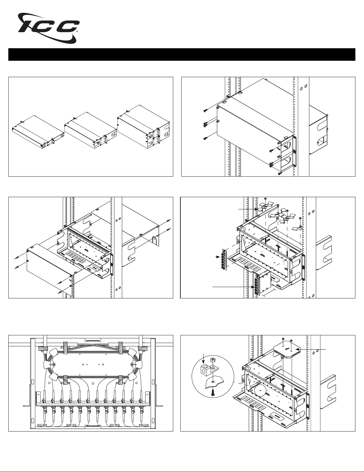
3 panel 6 panel 12 panel
We offer 3 sizes of enclosures. Mounting is similar for all of them.
Step 2. Remove the front and rear covers.
Step 1. Mount the enclosure to a 19” distribution rack with #12-24 rack screws.
Note: It is recommended to mount the enclosure above eye level.
Cable management spool
Adapter panel
MPO cassette
3.56”
Step 3. Install cable management spools and secure them using screw nuts.
Spools can be confi gured and stacked in a variety of ways depending on your
preference. Next, install fi ber optic adapter panels or MPO cassettes. Note:
MPO cassettes require more room, so the spools will have to be removed.
Grounding lug Splice tray
Step 4. Follow proper fi ber bend radius standard and route cable around
spools. Be sure to loop fi bers into the tray, and add slack to allow the tray
to slide out.
Optional: If splicing or grounding is required then install a splice tray or
grounding lug. Both are sold separately.
888-ASK-4ICC csr@icc.com icc.com
© Copyright 2013, ICC. ICC and ICC logo are registered trade name and trademark. All rights reserved. MSR-0521-RevA
Page 2

Slide-Out Fiber Optic Rack Mount Enclosures
INSTALLATION INSTRUCTIONS
A
ICFORE31RM
3 panel, 1 RMS*
3 panel
A
Rack mount fi ber optic enclosure
B
Cable management spools 4 pcs. 4 pcs. 4 pcs.
C
Hook and loop ties
#12-24 rack screws 4 pcs. 4 pcs. 8 pcs.
D
E
M5 x 0.8 screw nuts 4 pcs. 4 pcs. 4 pcs.
1 pc.
10 pcs. 10 pcs. 10 pcs.
ICFORE62RM
6 panel, 2 RMS*
6 panel
1 pc.
12 panel
1 pc.
B
FEATURES AND BENEFITS
• Enclosures are designed with a slide out tray with front and rear metal covers
• Made of durable 18 gauge steel with a black powder coated fi nish
• Available in 1, 2 and 4 RMS
• Holds adapter panels or MPO cassettes: 1 RMS holds 3, 2 RMS holds 6 and 4 RMS holds 12
• Holds splice trays: 1 RMS holds 2, 2 RMS holds 3 and 4 RMS holds 5
• *1 RMS (rack mount space) = 1.75” height
ICFORET4RM
12 panel, 4 RMS*
C
D
E
OPTIONAL ACCESSORIES
LC HD 10G Fiber Adapter Panel
ICFOPL161G 6 LC quad aqua
adapters, 24 fi bers
• LC to LC
• 10G aqua adapters
• Metal sleeves
• Supports multimode
LC HD 10G Fiber MPO Cassettes
ICFC24ML1G 6 LC quad aqua
adapters, 24 fi bers
ICFC12ML1G 6 LC duplex aqua
adapters, 12 fi bers
• LC to LC
• 10G aqua adapters
• 50/125m (OM3)
• Metal sleeves
• Supports multimode
LC 10G Fiber Jumpers
ICFOJ1G6zz1 Simplex
ICFOJ1G7zz
• LC to LC
• 50/125m (OM3)
• OFNR riser rated cable
• Supports multimode
Length (zz1) = 01, 02, 03, 05, 07, 10 meters
1
Duplex
Splice Tray
ICFOSKFM12
• Supports 12 fi ber splices
888-ASK-4ICC csr@icc.com icc.com
© Copyright 2013, ICC. ICC and ICC logo are registered trade name and trademark. All rights reserved. MSR-0521-RevA
 Loading...