

Page 1
4-Post Adjustable Distribution Rack
INSTALLATION INSTRUCTIONS
CUSTOMER CARE / TECHNICAL SUPPORT • CSR@ICC.COM / 888-ASK-4-ICC (275-4422)
Premium
Products
I Proven
Performance
I Competitive
Prices
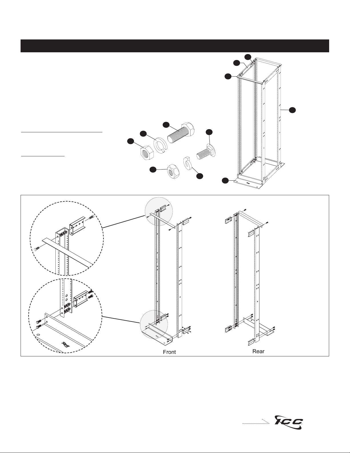
4-Post Adjustable Distribution Rack
Ensure all parts and hardware is included in
the packaging box. Box should contain:
ICCMSR4P84
A. (2) Top Angles
B. (2) Base Angles
C. (4) Side Channels
D. (4) Extension Channels
E. (8) Extension Brackets
Product Specifications
Material:
A. Side Rails: 6063 T-6 Alum. 3" C-Channels
B. Top Angle & Base Angle: 6061 T-6 Alum.
C. Extension Bracket and Extension Channel: 12GA CRS
Thread:
A.#12-24 UNC Per ANSI/EIA Spacing
2. Determine the desired width of the rack. NOTE: The rack width is adjustable from 27" min. to 32" max.
Fig. 1
3. Lay (2) Side Channels on a flat surface with the open channels facing inward. Place one (1) top angle across the front of the Side Channels. Install
two (2) 3/8-16 bolts, lock washers, and nuts to secure the top angle with the front of the Side Channels. Place (4) Extension Brackets on the rear side
of the channel. Secure the Extension Brackets to the rear of the Side Channels with (2) 3/8-16 bolts, lock washers, and nuts. Place one Base Angle
across the bottom end of the side rails. Secure the Base Angels to the Side Channels with (4) 3/8-16 bolts, lock washers, and nuts. NOTE: HAND
TIGHTEN ALL NUTS ONLY.
Repeat the process to assemble the rear side.
Recommended Hardware (sold separately)
ICCMSRFLKT -Rack Floor Mount Kit, Concrete
ICCACSS01BK -#12-24 X 5/8 Pilot Point Rack Screw
F. (24) 3/8-16 Bolts
G. (24) 3/8 Lock Washers
H. (24) 3/8-16 Nuts
I. (16) 1/4-20 Carriage Bolts
J. (16) 1/4-20 Lock Washers
K. (16) 1/4-20 Nuts
E
A
B
C
D
Fig. 1
F
G
H
I
J
K
Page 2
ASSEMBLY INSTRUCTIONS
© Copyright 2007, ICC. ICC and ICC logo are registered trade name and trademark. All rights reserved. MSR-0442 REV A
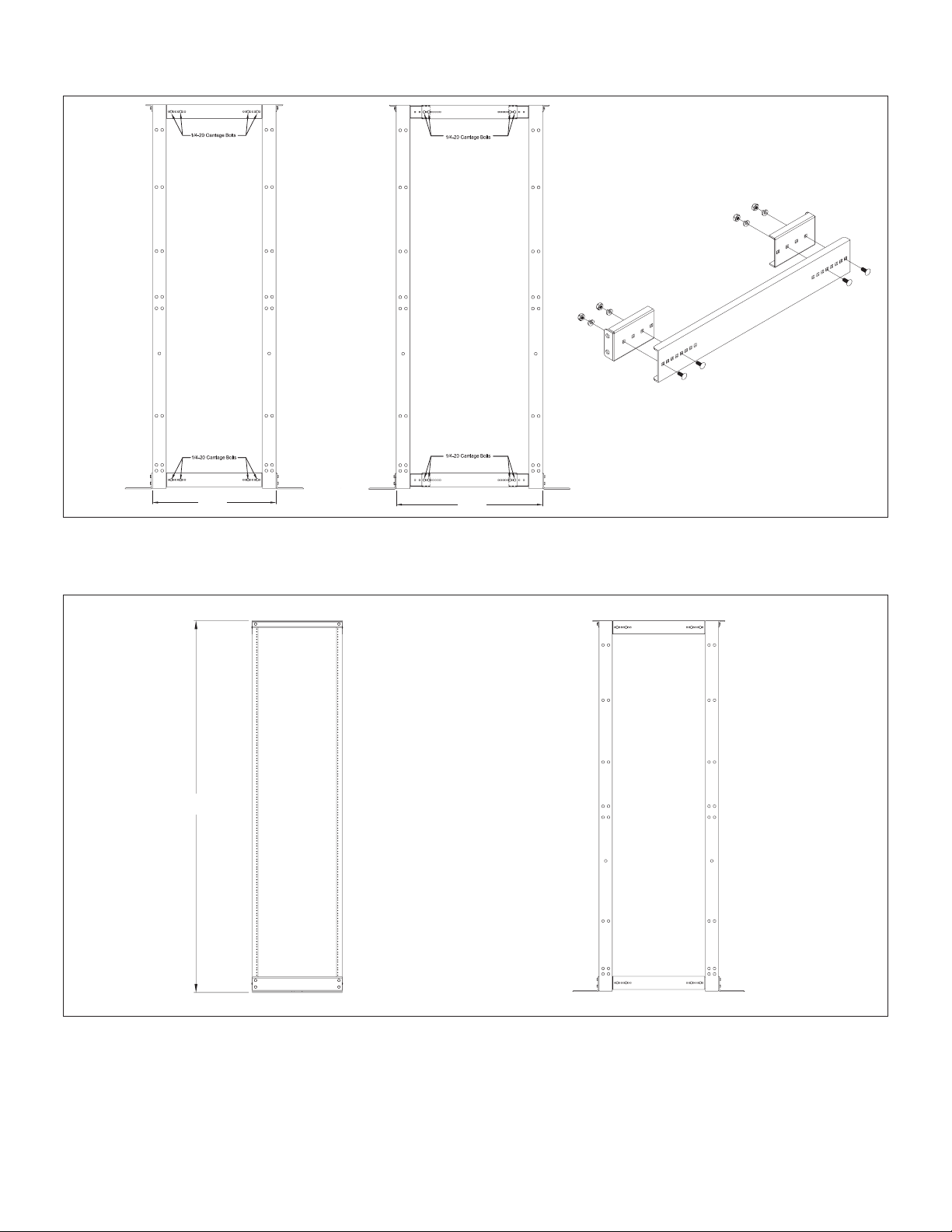
4. Install the (4) Extension Channels according to the chosen width of the rack. Use the (16) 1/4-20 Carriage Bolts, lock washers, and nuts to secure
the Extension Channels to the Extension Brackets. NOTE: The location of the carriage bolts will depend on the distance between the front and rear
side channels. Hand tighten all nuts only.
5. Stand the assembly up and check for squareness. Make sure the Base is level and will rest on a flat surface.
6. Tighten all bolts to approximately 25-30 lbs/ft of torque.
7. 4-Post Distribution Rack shall resemble the illustration above after assembly is complete.
27.00
32.00
84.00
 Loading...