

ICC ETH-1000 Quick Start Manual
ICC
INDUSTRIAL CONTROL COMMUNICATIONS, INC.
Page 1 of 10 05.23.2014
0720-160-MC
1600 Aspen Commons, Suite 210
Middleton, WI, USA 53562
Tel: (608) 831-1255
Fax: (608) 831-2045
Email: sales@iccdesigns.com
ETH-1000 Chillgard LC Quick Start Guide for BACnet
MS/TP
This document provides a brief overview of the connections and settings that must be used to connect a
preconfigured ETH-1000 gateway to a MSA Chillgard LC Refrigerant Monitor. This document also contains the
BACnet object mapping for the application and some troubleshooting tips. For more information, please refer to
the ETH-1000 User’s Manual available at http://www.iccdesigns.com/products/millennium/eth-1000.html.
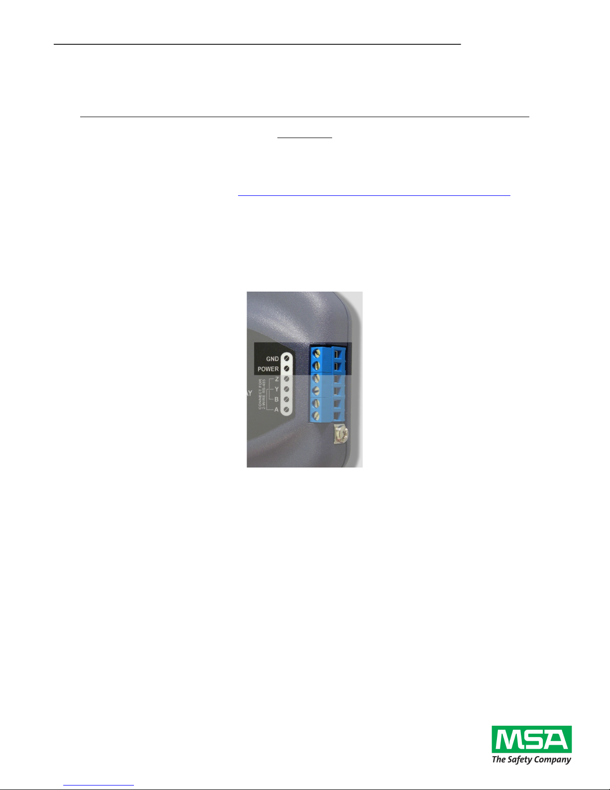
Wiring
Power Supply Wiring
A 7 – 24V DC power supply must be connected to the gateway’s terminal block at terminals TB:5 (POWER) and
TB:6 (GND) as highlighted in Figure 2.
Figure 1: Terminal Block Power Supply Connections
ICC
INDUSTRIAL CONTROL COMMUNICATIONS, INC.
Page 2 of 10 05.23.2014
0720-160-MC
1600 Aspen Commons, Suite 210
Middleton, WI, USA 53562
Tel: (608) 831-1255
Fax: (608) 831-2045
Email: sales@iccdesigns.com
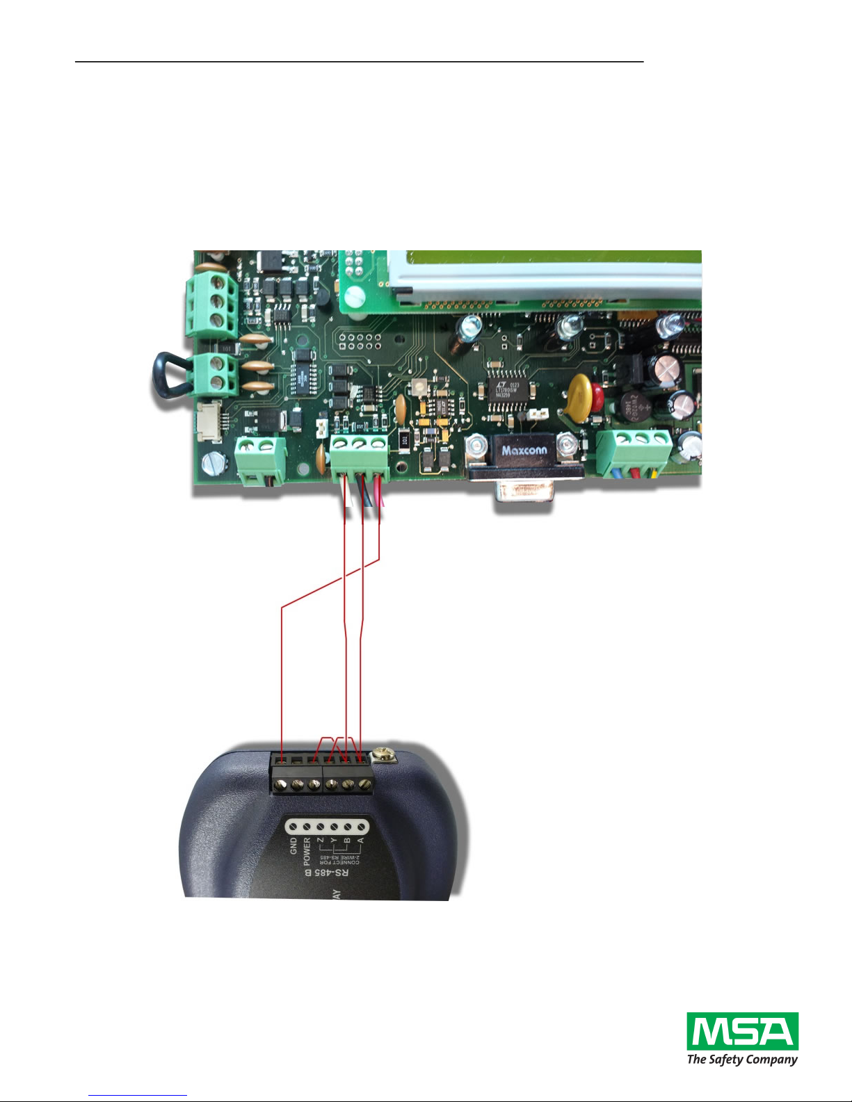
Wiring the Gateway to the Chillgard LC
Connect the “RS-485 To Sensor Module” terminals −, +, and G on the Chillgard LC to the gateway’s terminal
block at terminals TB:2 (B), TB:1 (A), and TB:6 (GND) as shown in Figure 2. This terminal block on the Chillgard
LC will have wires for both the gateway and any sensors connected to it. Additionally, a jumper wire must be
placed on the gateway’s terminal block between terminals TB:1 (A) and TB:3 (Y). Another jumper wire must be
placed between terminals TB:2 (B) and TB:4 (Z). as shown in Figure 2.
Figure 2: Gateway and Chillgard LC Connections
ICC
INDUSTRIAL CONTROL COMMUNICATIONS, INC.
Page 3 of 10 05.23.2014
0720-160-MC
1600 Aspen Commons, Suite 210
Middleton, WI, USA 53562
Tel: (608) 831-1255
Fax: (608) 831-2045
Email: sales@iccdesigns.com
Customizing the ETH-1000’s Configuration
The ETH-1000 can be configured via USB using the ICC Configuration Studio. Certain network settings and
BACnet settings may need to be modified to match a specific network configuration. To modify the gateway’s
configuration, open the ICC Configuration Studio and connect the gateway via the included USB cable. The
software will automatically recognize the connected device and upload the current configuration file stored on the
gateway. The configuration must be downloaded back to the gateway after making any changes. The latest ICC
Configuration Studio is available at http://www.iccdesigns.com/icc-configuration-studio.html.
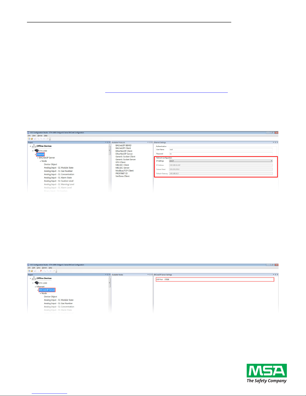
Ethernet Network Settings
The network settings may need to be modified to be compatible with your network. These settings can be
modified in the ICC Configuration Studio by selecting “Ethernet” in the Project Pane and changing the settings in
the Settings Pane as shown in Figure 3.
Figure 3: Network Settings
BACnet Communications Settings
The UDP Port, Device Name, and Device Instance may need to be modified to be compatible with your network.
These settings can be modified in the ICC Configuration Studio by selecting the corresponding items in the
Project Pane and changing the settings in the Settings Pane. The UDP Port can be changed by selecting
“BACnet/IP Server” and entering the desired UDP port number in the UDP Port field as shown in Figure 4. The
Device Name and Instance can be changed by selecting “Device Object” and entering a value in the Device
Name and Instance Number fields as shown in Figure 5. The default settings for the gateway are shown in Error!
Not a valid bookmark self-reference..
Figure 4: BACnet/IP UDP Port
 Loading...