

Page 1
ICC
Instruction M anual
INDUSTRIAL CONTROL COMMUNICATIONS, INC.
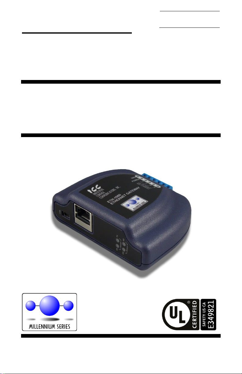
ETH-1000
Multiprotocol Ethernet /
RS-485 Gateway
October 2, 2014
ICC #10724 © 2014 Industrial Control Communications, Inc.
Page 2

ICC
ETH-1000 User's Ma nua l
Part Number 10724
Printed in U.S.A.
©2014 Industrial Control Communications, Inc.
All rights reserved
NOTICE TO USERS
Industrial Control Communications, Inc. reserves the right to make changes and
improvements to its products without providing notice.
Industrial Control Communications, Inc. shall not be liable for technical or
editorial omissions or mistakes in this manual, nor shall it be liable for incidental
or consequential damages resulting from the use of information contained in this
manual.
INDUSTRIAL CONTROL COMMUNICATIONS, INC.’S PRODUCTS ARE NOT
AUTHORIZED FOR USE AS CRITICAL COMPONENTS IN LIFE-SUPPORT
DEVICES OR SYSTEMS. Life-support devices or systems are devices or
systems intended to sustain life, and whose failure to perform, when properly
used in accordance with instructions for use provided in the labeling and user's
manual, can be reasonably expected to result in significant injury.
No complex software or hardware system is perfect. Bugs may always be
present in a system of any size. In order t o prev ent danger t o l if e or property, it is
the responsibility of the system designer to incorporate redundant protective
mechanisms appropriate to the risk involved.
This user’s manual may not cover all of the variations of interface applications,
nor may it provide information on every possible contingency concerning
installation, programming, operation, or maintenance.
The contents of this user’s manual shall not become a part of or modify any prior
agreement, commitment, or relationship between the customer and Industrial
Control Communications, Inc. The sales contract contains t he entire obligation of
Industrial Control Communications, Inc. The warranty contained in the contract
between the parties is the sole warranty of Industrial Control Communications,
Inc., and any statements contained herein do not create new warranties or
modify the existing warranty.
Any electrical or mechanical modificat ions to this equipment without prior written
consent of Industrial Control Communications, Inc. will void all warranties and
may void any UL/cUL listing or other safety certifications. Unauthorized
modifications may also result in equipment damage or personal injury.
1
Page 3

ICC
• Please use the interface only when the ambient temperature of the
Operating Environment
Installation and Wiring
Usage Precautions
environment into which the unit is installed is within the following
specified temperature limits:
Operation: -10 ∼ +60°C (+14 ∼ +140°F)
Storage: -40 ∼ +85°C (-40 ∼ +185°F)
• Avoid installation locations that may be subjected to large shocks or
vibrations.
• Avoid installation locations that may be subjected to rapid changes in
temperature or humidity.
• Proper ground connections are vital for both safety and signal reliability
reasons. Ensure that all electrical equipment is properly grounded.
• Route all communication cables separate from high-voltage or noiseemitting cabling (such as ASD input/output power wiring).
2
Page 4

ICC
TABLE OF CONTENTS
1. Introduction ..................................................................................5
2. Features ........................................................................................6
3. Gateway Concepts .......................................................................8
4. Precautions and Specifications ................................................10
4.1 Installation Precautions ...................................................................... 10
4.2 Maintenance Precautions................................................................... 11
4.3 Inspection .......................................................................................... 11
4.4 Maintenance and Inspection Procedure ............................................. 11
4.5 Storage ............................................................................................. 12
4.6 Warranty............................................................................................ 12
4.7 Disposal ............................................................................................ 12
4.8 Environmental Specifications ............................................................. 12
5. Gateway Overview .....................................................................13
5.1 Power Supply Electrical Interface ....................................................... 14
5.2 Ethernet Port ..................................................................................... 14
5.3 Power over Ethernet (PoE) ................................................................ 15
5.4 RS-485 Port Electrical Interface ......................................................... 15
6. Installation ..................................................................................17
6.1 Mounting the Gateway ....................................................................... 17
6.1.1 Panel / Wall Mounting ................................................................. 17
6.1.2 DIN Rail Mounting ....................................................................... 18
6.2 Wiring Connections ............................................................................ 19
6.3 Grounding ......................................................................................... 19
7. LED Indicators ............................................................................20
7.1 Module/Network Status ...................................................................... 20
7.2 RS-485 Network Status ..................................................................... 21
7.3 Ethernet Status .................................................................................. 21
8. Configuration Concepts ............................................................22
8.1 ICC Configuration Studio ................................................................... 22
8.2 General Object Editing Activities ........................................................ 24
8.2.1 Device Settings ........................................................................... 25
8.2.2 USB Virtual COM Port Settings ................................................... 26
8.2.3 USB Serial Capture Window ....................................................... 27
8.3 Ethernet Settings ............................................................................... 29
8.3.1 Authentication ............................................................................. 29
8.3.2 Network Configuration ................................................................ 29
3
Page 5

ICC
8.4 Internal Logic Settings ....................................................................... 30
8.4.1 Alarms ........................................................................................ 30
8.4.2 Fail-safe Values .......................................................................... 32
8.4.3 Database Logic ........................................................................... 33
8.5 Service Objects and Diagnostics Objects ........................................... 36
9. Interacting With the Filesystem ................................................37
9.1 Using FTP with Windows Explorer ..................................................... 38
9.2 Using FTP with a Windows Command Prompt ................................... 39
9.3 Using FTP with Core FTP LE ............................................................. 42
10. Embedded Web Server ..............................................................44
10.1 Overview ........................................................................................... 44
10.2 Authentication .................................................................................... 45
10.3 Activity Panel ..................................................................................... 45
10.4 Navigation Menu Tree........................................................................ 46
10.5 Monitor Menu .................................................................................... 47
10.5.1 Activity Indicator ......................................................................... 47
10.5.2 Database .................................................................................... 47
10.6 INCON Clien t Menu ........................................................................... 48
10.7 BBMD Server Menu ........................................................................... 49
10.7.1 BBMD Status .............................................................................. 49
10.7.2 Broadcast Dist ribution Table (BDT) ............................................. 49
10.7.3 Foreign Device Table (FDT) ........................................................ 50
10.8 Dashboard Menu ............................................................................... 51
10.8.1 Gauge Panel Navigation ............................................................. 51
10.8.2 Gauge Panel Configuration ......................................................... 52
10.8.3 Activity Indicator ......................................................................... 55
10.8.4 Submitting Changes.................................................................... 55
11. RS-485 Drivers............................................................................56
12. Ethernet Drivers .........................................................................57
13. Troubleshooting .........................................................................58
14. Appendix A: Database Endianness ..........................................60
14.1 Modbus - PROFIBUS Example .......................................................... 62
14.2 Modbus - DeviceNet Example ............................................................ 63
14.3 BACnet - DeviceNet Example ............................................................ 64
14.4 BACnet - Modbus Analog Element Example ...................................... 66
14.5 BACnet - Modbus Binary Element Example ....................................... 67
15. Appendix B: Diagnostics Objects .............................................69
16. Appendix C: BACnet PICS.........................................................71
4
Page 6

ICC
1. Introduction
Congratulations on your purchase of the ICC ETH-1000 Multiprotocol Ethernet
Communications Gateway. This gateway allows information to be transferred
seamlessly between various industrial Ethernet networks and one of several RS485-based networks. In addition to the supported fieldbus protocols, the gateway
hosts a USB interface for configuring the gateway via a PC.
Before using the gateway, please familiarize yourself with the product and be
sure to thoroughly read the instructions and precautions contained in this
manual. In addition, please make sure that this instruction manual is delivered to
the end user of the gateway, and keep this instruction manual in a safe place for
future reference or unit inspection.
For the latest information, support software and firmware releases, please visit
http://www.iccdesigns.com
Before continuing, please take a moment to ensure that you have received all
materials shipped with your kit. These items are:
• ETH-1000 Gateway in plastic housing
• Doc um ent at ion CD-ROM
• DIN rail adapter w it h two pre-mounted screws
• Four black rubber feet
• USB cable
Note that different gateway firmware versions may provide varying levels of
support for the various protocols. For optimal performance, always ensure that
you are using the latest version of the ICC Configuration Studio and included
firmware.
This manual will primarily be concerned with the gateway’s hardware
specifications, installation, wiring, configuration and operational characteristics.
To maximize the abilities of your new gateway, a working familiarity with this
manual will be required. This manual has been prepared for the gateway
installer, user, and maintenance personnel. With this in mind, use this manual to
develop a system familiarity before attempting to install or operate the gateway.
.
5
Page 7

ICC
• 300
• 2400
• 4800
• 38400
• 57600
2. Features
Supporte d P rotocols
The gateway provides support for a variety of Ethernet and RS-485 based
fieldbus protocols. Refer to section 11 and section 12 for detailed information on
each specific supported driver.
Supporte d Ba ud Rates
The gateway supports the following baud rates on the RS-485 port:
• 600
• 1200
Note that not all protocols support every baud rate listed above. Refer to section
11 for more information.
Field-Upgradeable
As new firmware becomes available, the gateway can be upgraded in the field by
the end-user. Refer to section 8.1 for more information.
USB Inter f a c e
The gateway can be connected to a PC via a USB mini type-B cable. This
simultaneously supplies power while providing the ability to configure the
gateway, monitor data, and update firmware on the device using the ICC
Configuration Studio. Refer to section 8.1 for more information.
USB Virtual COM Port Int e rface
The gateway can be configured to enumerate as a USB virtual COM port,
allowing a PC to directly communicate to the gateway using any supported serial
protocol, tunnel through the gateway to communicate on the connected RS-485
bus, or capture network traffic on the RS-485 port without impacting
communications. Refer to section 8.2.2 for more information.
Power over Ethernet (PoE) Enabled
The gateway can be externally powered according to the PoE specification (IEEE
802.3af). Refer to section 5.2 for more information.
Alarm Eva luation wit h E m a il Notification
The gateway can autonomously monitor any database address and send emails
to up to four recipients when a certain condition is detected. Alarm conditions
have both value and time constraints, and can be configured to retrigger at a
fixed interval as long as the alarm condition continues to be satisfied. Twenty
individually-configurable alarms are available. Refer to section 8.4.1 for more
information.
• 9600
• 19200
• 76800
• 115200
6
Page 8

ICC
Embedded Web Server
The gateway supports real-time web browser-based interaction via an Adobe®
Flash Player plug-in. This includes support for configuration, database
interaction, and a dashboard GUI with multiple panels, each of which can be
configured to display data in a variety of meter/graph/gauge formats. Refer to
section 10 for more information.
User-Configur a ble Networ k Timeouts
The gateway can be configured to perform a specific set of actions when network
communications are lost. This allows each address in the database to have its
own unique “fail-safe” condition in the event of network interruption (support for
this feature varies depending on the protocol). Refer to section 8.4.2 f or more
information.
PLC-Style Da t a ba s e Manipu la t ion Operations
A variety of database logic operations are included which provide PLC-style
manipulation of database values. Categories such as logical, arithmetic and
filtering operations allow for autonomous control over value modification and data
movement within the database. High-level signal conditioning is also realizable
via the construction of compound formulas derived from the elemental building
block operations provided. Refer to section 8.4.3 for more information.
Flexible Mounting Ca pabilit ie s
The gateway includes all hardware for desktop, panel/wall and DIN-rail mounting
capabilities. Refer to section 6.1 for more information.
7
Page 9

ICC
3. Gateway Concepts
The ETH-1000 is a member of the Millennium Series communication gateways.
Members of this family are designed to provide a uniform interface, configuration
and application experience. This commonality reduces the user’s learning curve,
reducing commissioning time while simplifying support. All Millennium Series
gateways are configured using the ICC Configuration Studio. The ETH-1000
provides simultaneous support for many different communication protocols,
allowing complex interchanges of data between otherwise incompatible
networks.
The heart of the Millennium Series concept is its internal database. The database
is a 4 KB, byte-wise addressable data array. This provides a total size of 4096
bytes for the entire database, referred to as DB
The database allows data to be routed from any supported network to any other
supported network. Data may be stored into the database in either big-endian
style (meaning that if a 16-bit or 32-bit value is stored in the database, the most
significant byte will start at the lowest address) or little-endian style (meaning that
if a 16-bit or 32-bit value is stored in the database, the least significant byte will
start at the lowest address).
The other fundamental aspect of the Millennium Series is the concept of a
configurable “service object”. A service object is used for any master/client
protocol to describe what service (read or write) is to be requested on the
network. The gateway will cycle through the defined service objects in a roundrobin fashion; however, the gateway does implement a “write first” approach.
This means that the gateway will perform any outstanding write services before
resuming its round-robin, read request cycle.
Additionally, the database and service objects provide the added benefit of “data
mirroring”, whereby current copies of data values (populated by a service object)
are maintained locally within the gateway itself. This greatly reduces the requestto-response latency times on the various networks, as requests (read or write)
can be entirely serviced locally, thereby eliminating the time required to execute
a secondary transaction on a different network.
In order to facilitate the free scaling and conversion of native data values, a userconfigurable “multiplier” and “data type” exist for some network configurations. All
network values are scaled by a multiplier prior to being stored into the database
or after being retrieved from the database. The data type is used to determine
how many bytes are allocated for the value in the database, whether the value
should be treated as signed or unsigned, and whether the value should be
interpreted as an integer or a floating point number upon retrieval from the
database.
A typical use of the multiplier feature is to preserve the fractional components of
a network value for insertion into the database. For example, if the floating-point
value “3.19” is read by the gateway from a remote BACnet device, then we could
use a multiplier value of 0.01 to preserve all of the significant digits of this value:
the network representation (3.19) will be divided by the multiplier value (0.01) to
in the protocol driver manuals.
Size
8
Page 10

ICC
obtain a resultant value of 319, which will then be inserted into the database.
Similarly, when a value in the database corresponding to a specific service object
is changed (which therefore requires that this updated value be written to the
associated remote device on the network), the service object’s multiplier value
will first be multiplied by the database value in order to obtain the resultant
network value. For example, if 3000 is written to the database at a location
corresponding to a certain service object on the other port, and that service
object’s multiplier value is 0.1, then the database value (3000) will be multiplied
by the multiplier value (0.1) to obtain the resultant network value of 300.0, which
will then be written to the network as a native floating point value.
An appropriate data type should be selected based on the range of the network
data values. For example, if the value of an Analog Output on a remote BACnet
device can vary from –500 to 500, a 16-bit signed data type should be used. If
the value can only vary from 0 to 150, for example, an 8-bit unsigned data type
may be used. Care must be taken so that a signed data type is selected if
network data values can be negative. For example, if 0xFF is written to the
database at a location corresponding to a service object with an 8-bit unsigned
data type, the resultant network value will be 255
However, if 0xFF is written to the database at a location corresponding to a
service object with an 8-bit signed data type, the resultant network value will be
(again, assuming a multiplier of 1). It is also important to select a data type
−1
10
large enough to represent the network data values. For example, if a value of
257 is read by the gateway from a remote device and the data type
corresponding to that service object is 8-bit unsigned, the value that actually will
be stored is 1 (assuming a multiplier of 1). This is because the maximum value
that can be stored in 8-bits is 255. Any value higher than this therefore results in
overflow.
The Millennium Series gateways also provide a powerful data-monitoring feature
that allows the user to view and edit the database in real time, as well as view the
status of ser vice objects via the ICC Configuration Studio’s Database panel when
connected via USB to a PC. The ability to interact with the database is also
available via the embedded web server.
When properly configured, the gateway will become essentially “transparent” on
the networks, and the various network devices can engage in seamless dialogs
with each other.
(assuming a multiplier of 1).
10
9
Page 11

ICC
4. Precautions and Specifications
Rotating shafts and electrical equipment can be hazardous.
Installation, operation, and maintenance of the gateway shall be
performed by Qualified Pe rsonnel only.
Qualified Personnel shall be:
• Familiar with the construction and function of the gateway, the
equipment being driven, and the hazards involved.
• Trained and authorized to safely clear faults, ground and tag
circuits, energize and de-energize circuits in accordance with
established safety practices.
• Trained in the proper care and use of protective equipment in
accordance with established safety practices.
Installation of the gateway should conform to all applicable
Nationa l E le c t rical Code (NEC) Requirements For Electrical
Installations, all regulations of the Occupational Safe t y a nd
Health Admin ist ra tio n, and any other applicable national,
regional, or industry codes and standards.
DO NOT install, operate, perform maintenance, or dispose of this
equipment until you have read and understood all of the following
product warnings and user directions. Failure to do so may result in
equipment damage, operator injury, or death.
4.1 Installation Precautions
• Avoid installation in areas where vibration, heat, humidity, dust,
metal particles, or high levels of electrical noise (EMI) are
present.
• Do not install the gateway where it may be exposed to
flammable chemicals or gasses, water, solvents, or other fluids.
• Where applicable, always ground the gateway to prevent
electrical shock to personnel and to help reduce electrical noise.
Note: Conduit is not an acceptable ground.
• Follow all warnings and precautions and do not exceed
equipment ratings.
10
Page 12

ICC
4.2 Maintenance Precautions
• Do Not attempt to disassemble, modify, or repair the gateway.
Contact your ICC sales representative for repair or service
information.
• If the gateway should emit smoke or an unusual odor or sound,
turn the power off immediately.
• The system should be inspected periodically for damaged or
improperly functioning parts, cleanliness, and to determine that
all connectors are tightened securely.
4.3 Inspection
Upon receipt, perform the following checks:
• Inspect the unit for shipping damage.
• Chec k for loos e, broken, damaged or missing parts.
Report any discrepancies to your ICC sales representative.
4.4 Maintenance and Inspection Procedure
Preventive maintenance and inspection is required to maintain the gateway in its
optimal condition, and to ensure a long operational lifetime. Depending on usage
and operating conditions, perform a periodic inspection once every three to six
months.
Inspection Points
• Chec k that there are no defects in any attached wire terminal crimp points.
Visually check that the crimp points are not scarred by overheating.
• V is ually check all wiring and cables for damage. Replace as necessary.
• Clean of f any accumulated dust and dirt.
• If us e of the interface is discontinued for extended periods of time, apply
power at least once every two years and confirm that the unit still functions
properly.
• Do not perf orm hi-pot tests on the interface, as they may damage the unit.
Please pay close attention to all periodic inspection points and maintain a good
operating environment.
11
Page 13

ICC
Indoors, less than 1000m above sea level, do not
gasses
4.5 Storage
• S t ore t he device in a well-ventilated location (in its shipping carton, if
possible).
• A v oid storage l ocations with extreme temperatures, high humidity, dust, or
metal particles.
4.6 Warranty
This gateway is covered under warranty by ICC, Inc. for a period of 12 months
from the date of installation, but not to exceed 18 months from the date of
shipment from the factory. For further warranty or service information, please
contact Industrial Control Communications, Inc. or your local distributor.
4.7 Disposal
• Contact the local or state environmental agency in your area for details on
the proper disposal of electrical components and packaging.
• Do not dis pose of the unit via incineration.
4.8 Environmental Specifications
Item Specification
Operating Environment
Operating Temperature
Storage Temperature
Relative Humidity
Vibration
Grounding Non-isolated, referenced to power ground
Cooling Method Self-cooled
This device is lead-free / RoHS-compliant.
expose to direct sunlight or corrosive / explosive
-10 ∼ +60°C (+14 ∼ +140°F)
-40 ∼ +85°C (-40 ∼ +185°F)
20% ∼ 90% (without condensation)
2
5.9m/s
{0.6G} or less (10 ∼ 55Hz)
12
Page 14
ICC
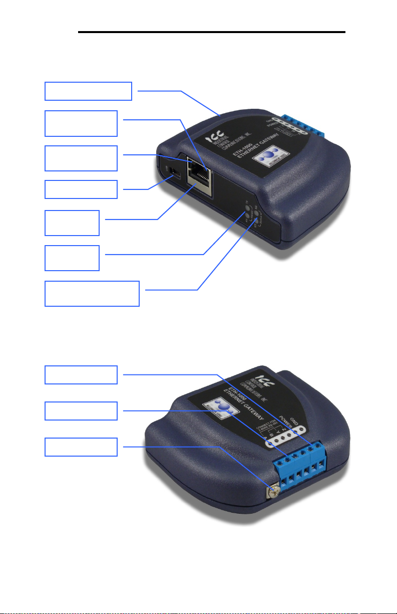
Gateway Overview (Front)
RS-485 TX
Shielded RJ45
Ethernet jack
USB connector
Ethernet activity
LED (green)
Ethernet link LED
(amber)
Module Status (MS) and
Network St atus (NS) LEDs
MAC ID (on bottom)
Chassis GND
RS-485 terminals
Power termi nal s
Gateway Overview (Back)
5. Gateway Overview
and RX LEDs
13
Page 15

ICC
5.1 Power Supply Electrical Interface
When the gateway is not plugged into a PC via the USB cable, it must be
powered by an external power source or via Power over Ethernet (PoE: refer to
section 5.2). When using an external power source connected to the gateway’s
power and ground terminals, ensure that the power supply adheres to the
following specifications:
Voltage rating ........................ 7 - 24VDC
Minimum Current rating.......... 150m A (@24VDC)
• ICC offers an optional 120VAC/12V DC power supply (ICC part number
10755) that can be used to power the gateway from a standard wall outlet.
• The power supply must be connected to the gateway’s terminal block at
terminals TB:5 (POWER) and TB:6 (GND) as highlighted in Figure 1.
Figure 1: Terminal Block P ow e r Supply Connections
5.2 Ethernet Port
The gateway supports an IEEE 802.3 10BASE-T/100BASE-TX Ethernet port.
The Ethernet port accepts standard CAT5-type 8-conductor unshielded twistedpair (UTP) patch cables. The single Ethernet port supports multiple simultaneous
protocols. The port is set for auto-negotiation to automatically select the network
speed and duplex.
14
Page 16

ICC
5.3 Power over Ethernet (PoE)
The gateway supports the IEEE 802.3af Power over Ethernet (PoE) standard as
a mode A or mode B powered device (PD). In mode A, the Ethernet jack pins 12 (pair #2 in T568B wiring) form one side of the DC supply and pins 3-6 (pair #3
in T568B) form the other side. These are the same two pairs used for data
transmission in 10Base-T and 100Base-TX, allowing the provision of both power
and data over only two pairs in such networks.
In mode B, the Ethernet jack pins 4-5 (pair #1 in both T568A and T568B cabling
standards) form one side of the DC supply and pins 7-8 (pair #4 in both T568A
and T568B) provide the return; these are the "spare" pairs in 10BASE-T and
100BASE-TX. Mode B power transmission, therefore, requires the use of a full
4-pair Ethernet cable.
The gateway enumerates itself as a power level class 0 device (12.95W max.
indicated consumption). T h e use of PoE endspan (“PoE switch”) or midspan
(“power injector”) power sourcing equipment (PSE) provides for the ability to
power the gateway without the necessity of connecting a dedicated power supply
to the power supply terminal block.
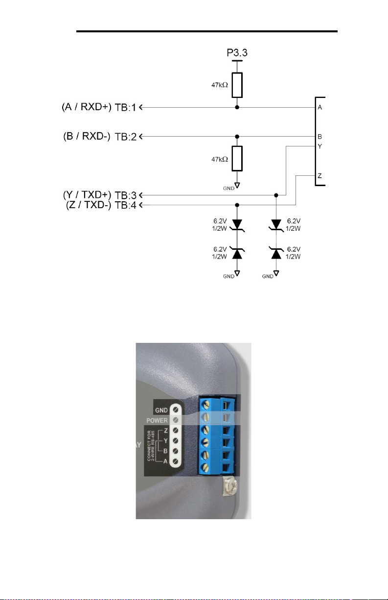
5.4 RS-485 Port Electrical Interface
In order to ensure appropriate network conditions (signal voltage levels, etc.)
when using the gateway’s RS-485 port, some knowledge of the network interface
circuitry is required. Refer to Figure 2 for a simplified network schematic of the
RS-485 interface circuitry. The port has 4 terminals for four-wire communication.
For two-wire communication, connect a jumper wire between TB:1 (A / RXD+)
and TB:3 (Y / TXD+) and a wire between TB:2 (B / RXD-) and TB:4 (Z / TXD-).
15
Page 17
ICC
Figure 2: RS-485 Interface Circuitry Schematic
Figure 3 highlights the terminals on the gateway’s terminal block that are specific
to RS-485 connections.
Figure 3: Termina l Bloc k RS -485 C onnections
16
Page 18

ICC
6. Installation
The gateway’s installation procedure will vary slightly depending on the mounting
method used. Before mounting the gateway, install the 4 black rubber feet
(Figure 4) onto the bottom of the enclosure.
Figure 4: R ubber Feet
6.1 Mounting the Gateway
The gateway may be mounted on a panel, a wall or a DIN rail. In all cases, the
gateway is mounted using the two keyhole-shaped screw holes on the bottom of
the enclosure. A DIN rail adapter with two pre-mounted screws is provided for
mounting the gateway on a DIN rail. The user must choose the appropriate
hardware for mounting the gateway on a panel or wall. When choosing screws
for panel or wall mounting, ensure the head size matches the keyhole screw
holes on the back of the enclosure. The following describes the method for the
two mounting options.
6.1.1 Panel / Wall Mounting
To mount the gateway on a panel or wall, drill two holes 25mm apart vertically.
Screw two screws into the holes and mount the gateway on the screws.
Figure 5: Pa nel / Wa ll Mounting Dia gram
17
Page 19

ICC
6.1.2 DIN Rail Mounting
The DIN rail adapter (Figure 6) can clip onto 35mm and G-type rails. To mount
the gateway to a DIN rail, clip the DIN rail adapter onto the DIN rail and mount
the gateway on the screws (the screws should already be seated into the adapter
at the proper height). Refer to Figure 7, Figure 8, and Figure 9.
Figure 6: D IN Rail Adapte r
Figure 8: U nit w it h Attached
DIN Rail Ada pt e r
Figure 7: D IN Rail Adapte r Attachment
Figure 9: Ex a m ple Insta lla tion
18
Page 20

ICC
6.2 Wiring Connections
Note that in order to power the unit, a power supply must also be installed. Refer
to sections 5.1 and 5.2 for more information.
1. Mount the unit via the desired method (refer to section 6.1).
2. Connect the various networks to their respective plugs/terminal blocks.
Ensure that any wires are fully seated into their respective terminal blocks,
and route the network cables such that they are located well away from any
electrical noise sources, such as adjustable-speed drive input power or
motor wiring. Also take care to route all cables away f rom any sharp edges
or positions where they may be pinched.
3. Take a moment to verify that the gateway and all network cables have
sufficient clearance from electrical noise sources such as drives, motors, or
power-carrying electrical wiring.
4. If not using PoE, connect an external power supply to the gateway’s RS-485
terminal block on the terminals labeled POWER and GND. Pay particular
attention to the proper polarity.
6.3 Grounding
Grounding is of particular importance for reliable, stable operation.
Communication system characteristics may vary from system to system,
depending on the system environment and grounding method used.
The gateway has one logic ground located on the RS-485 terminal block, which
serves as the ground reference for both power and RS-485 communication
signals.
CAUTION:
Note that there is a single chassis ground terminal adjacent to the RS-485
terminal block. This chassis ground terminal is NOT internally connected to the
“GND” terminal on the RS-485 terminal block. Do not make any logic grounding
connections to the chassis ground terminal.
Please be sure to consider the following general points for making proper ground
connections:
Grounding method c he c kpoints
1. Make all ground connections such that no ground current flows through the
case or heatsink of a connected electrical device.
2. Do not connect the gateway’s GND terminal to a power ground or any other
potential noise-producing ground connection (such as an adjustable-speed
drive’s “E” terminal).
3. Do not make connections to unstable grounds (paint-coated screw heads,
grounds that are subjected to inductive noise, etc.)
19
Page 21

ICC
A fatal error has occurred. The number of sequential
the error code.
No power / no IP address / no PROFINET IO
connection
Gateway has an IP address and one or more
have been established with a client
Gateway has an IP address but no EtherNet/IP
connections have been established with a client
7. LED Indicators
The gateway contains several different LED indicators, each of which conveys
important information about the status of the unit and connected networks. These
LEDs and their functions are summarized here.
7.1 Module/Network Status
The gateway has two dichromatic, stacked LEDs to indicate the status of the
module (MS) and the status of the Ethernet/IP network server driver (NS). On
startup, the LEDs blink a startup sequence: green-red-green-red. Always confirm
this sequence upon powering the gateway to ensure the device is functioning
properly. Refer to Table 1 and Table 2 for further details.
Table 1: Module Status LED
LED State Indication
Off No power
Green Gateway has power and is functioning normally
Flashing Green The gateway has established a USB connection
Flashing Red
Alternating Red/Green Startup sequence
Table 2: EtherNet/IP Network Status LED
LED State Indication
Off
Green
Flashing Green
Red Critical link failure / duplicate IP address
Flashing Red One or more EtherNet/IP connection s ti me d -out
Alternating Red/Green Startup sequence
blinks (followed by 2 seconds of OFF time) indicates
EtherNet/IP or PROFINE T IO server connections
20
Page 22

ICC
7.2 RS-485 Network Status
The gateway has one red and one green LED to indicate the status of the RS485 network.
Green (TX) LED ..... Lights when the gateway is transmitting data on the RS-485
port.
Red (RX) LED........ Lights when the gateway is receiving data on the RS-485
port. Note that this does not indicate the validity of the data
with respect to a particular protocol: only that data exists and
is being detected. Also note that if a 2-wire RS-485 network
is in use, that the gateway’s RX LED will light in conjunction
with the TX LED (as transmitting devices on 2-wire RS-485
networks also receive their own transmissions).
7.3 Ethernet Status
The Ethernet jack contains two embedded LEDs which indicate the status of the
Ethernet physical layer
Amber LED ............ Et herne t link: lit whenever a viable Ethernet network is
connected to the port. The LED must be lit for any Ethernet
communication to occur.
Green LED ............ Et he rnet Activity: blinks briefly when Ethernet packets are
sent or received. The LED may appear solid green if there is
a large amount of network traffic.
21
Page 23

ICC
8. Configuration Concepts
8.1 ICC Configuration Studio
The gateway can be configured by a PC via a USB mini type-B cable. This
connection provides power to the device, so there is no need for any ext ernal
power supply while the gateway is attached to the PC.
The gateway is configured by the ICC Configuration Studio PC application, and
this section will provide only a brief introduction to the configuration concepts. For
more detailed information on how to install and use the Configuration Studio,
refer to the separately-available training resources.
Offline Device Configuration
A device can be added to the Project panel for offline configuration by first
selecting the Offline Dev ic e s list heading and then:
• Double-c lic king on it in the Availa ble De vices panel.
• Right-clicking on it in the Available Devices panel a nd c hoos ing Add from
the context-sensitive menu.
• Hi tting the <ENTER> key on the keyboard when the device is selected in the
Available Devices panel.
• Dragging it from the Available Devic e s panel into the Project panel.
The device will then be added to the list of Offline Devic es. A valid offline
configuration can be downloaded to a compatible online device at any time.
Online Device Configurati on
All connected devices are automatically loaded and added to the list of Online
Devices. When a device is disconnected, its configuration is moved to the list o f
Offline Devices.
Removing an Offline Device from a Project
An offline device can be removed from a project by:
• Selecting the device in the Project panel and dragging it. A trash can icon
will appear at the bottom of the Project panel, and dragging the device to
the trash will then delete it from the project.
• Hit t ing t he <DELETE> key on the keyboard when the device is selected in
the Project panel.
• Right-clicking on the device in the Project panel and choos in g Remove from
the context-sensitive menu.
• Selecting Remove Selected Item from the Edit menu when the device is
selected.
• Clic king on the Remove button in the toolbar when the device is selected.
22
Page 24

ICC
Loading a Configura t ion from an X ML File
This feature is intended to support the import of configuration files created with
the older Gateway Configuration Utility. To load a configuration from an XML file
stored on the PC, click File…Open Project, select the “XML Files (* .xml)” file
type, and open the XML configuration file.
Importing a Configura t ion from a P roject File or an XML File
An existing project file or configuration XML file can be imported into the
currently-active project. Click File…Import P roject, and then select the desired
*.icsproj or *.xml file. The contents of the imported file will be merged with the
active project.
Downloading a Confi guration to a De v ice
To download a configuration to an online device, first select the device and then
navigate to Device…Down load Confi guration to Dev ice. If the device selected
was already in the list of Online Devices, t hen t he conf igurat ion will be
downloaded to this device. If the device selected was in the list of Offline
Devices, then the configuration will be downloaded to the online device, and the
device will be removed from the list of Offline Devices. Note that to prevent
ambiguity with respect to which online device is being targeted, the studio will
allow downloading from an offline device only when a single instance of a
compatible device is online: if multiple compatible devices are currently online,
then disconnect all other devices until just the target device intended to receive
the configuration remains.
Note that there may be different driver firmware available for each RS-485
protocol. If necessary, the studio will automatically update the device with the
appropriate firmware prior to downloading the configuration. Do not power off t he
device once the download is in progress as this may corrupt the firmware and/or
the configuration.
Updating Firmware
The studio automatically manages firmware updates when downloading a
configuration to a device.
Resetting an Onli ne Device
To reset an on line device, first select the device in the Project panel and then
navigate to Device…Reset Device.
Interact ing with the Database
To interact with a device’s database, select the device in the Project panel and
then select the Database panel. If the Database panel is not visible, it can be
enabled via View…Database. When an online device is selected, data values
are updated from the device in real-time, and values can be edited by doubleclicking the desired location in the database.
Diagnostics
To monitor the status of service objects, select the device in the Project panel
and then select the Diagnostics panel. If th e Diagnostics panel is not visible, it
23
Page 25

ICC
can be enabled via View…Diagnostics. W hen an online device is selected,
diagnostics information is updated from the device in real-time. Individual
diagnostics objects can be selected by clicking on them in the list, and multiple
items can be selected by either <CTRL>+clicking on them (to select them
individually) or <SHIFT>+clicking on them (to select a range of items). Counter
values of all currently-selected diagnostics objects can be reset by clicking the
Reset Selected Counters button.
General Configura t ion Process
To configure a device, add the desired protocols for the various ports, configure
the communication settings (baud rate, parity, address, timeout, and scan
rate/response delay etc.), and configure any objects associated with the
respective protocols. Regardless of whether configuration changes are made to
an online or offline device, those changes will only take effect once the
configuration is downloaded to a device.
Note that numeric values can be entered not only in decimal but also in
hexadecimal by including “0x” before the hexadecimal number.
8.2 General Object Editing Activities
The following editing activities apply for all types of configuration objects and
project elements.
Adding an Object
To add an object, click on an item (protocol driver or Node, for example) in the
Project panel. Any available objects for that item will be listed in the Available
Objects panel (t he panel tit le depends on the currently-selected item). An object
can then be added to the item by:
• Double-c lic king on it.
• Right-clicking on it and choosing Add from t he context-sensitive menu.
• Hit t ing t he <ENTER> key on the keyboard when the object is selected.
• Dragging it int o the Project panel.
The object’s configurable fields can then be populated with valid values (where
applicable).
Viewing an O bject
In the Project panel, select a parent object to display a summary of all its child
objects. For example, selecting a protocol driver will display the driver’s
configuration in the Summary panel and list of current objects in the Object List
panel.
Updating a n O bject
To update an object, select the object in the Project panel and make any
required changes in the Settings panel.
24
Page 26

ICC
Deletin g a n O bje c t
An object can be deleted by performing one of the three following actions:
• Selecting the object in the Project panel and dragging it. A trash can icon
will appear at the bottom of the Project panel, and dragging the object to the
trash will then delete it from the project.
• Hit t ing t he <DELETE> key on the keyboard when the object is selected in
the Project panel.
• Right-clicking on the object in the Project panel and choosing Remove from
the context-sensitive menu.
• Selecting Remove Selected Item from the Edit menu when the object is
selected.
• Clic king on the Remove button in the toolbar when the object is selected.
Note that this action cannot be undone. Deleting an object will also delete all of
its child objects.
Copying an O bject
To copy an object, first click on an item in the Project panel. An object can then
be copied by:
• Right-clicking on it and choosing Copy from the context-sensitive menu.
• Hit t ing t he <CTRL+C> keys on the keyboard when the object is selected.
• Holding t he <CTRL> key and dragging the item in the Project panel.
• Selecting Copy Sele c t e d It e m from the Edit menu when the object is
selected.
• Clic king on the Copy button in the toolbar when the object is selected.
The object’s configurable fields can then be modified with valid values (where
applicable).
Reordering Object s
Objects can be reordered in the Project panel by dragging the item to the
desired location. If the item is dragged outside of the items in the project tree, it
will be moved to the end.
8.2.1 Device Settings
The following fields can be configured for a device. To view or edit device
settings, click on the device in the Project panel. The settings are then available
in the Settings panel.
Device Description
Each device added to a project can be individually tagged with a unique
description string of up to 32 characters in length. This allows the devices within
a project or an automation system to be clearly identifiable with their location or
functional purpose.
25
Page 27

ICC
Database Endianness Selection
Select the desired endianness for how data will be stored in the device’s internal
database for multi-byte data types. For more information on database
endianness, refer to Appendix A: Database Endianness.
8.2.2 USB Virtual COM Port Settings
The device can be configured to enumerate as a USB virtual COM port, providing
direct serial communications between the device and a PC through the USB
connection. The COM port can be used for various tasks, depending on the
selected mode. This section details the different functions of the virtual COM
port.
Mode
Select the desired mode for how the USB virtua l COM port will be used. The
available options are detailed below.
Serial Pass-Through
Select this option to cause the device to behave as a USB-to-serial
converter. Any data sent to the USB virtual COM port will be forwarded
to the physical serial port and any data received by the physical serial
port will be forwarded to the USB virtual COM port. Note that while the
device is in this mode all other functionality of the device is disabled,
regardless of other configuration settings.
Serial Redirect
Select this option to redirect communications from the selected serial
port on the device t o the USB virtual COM port. By selecting this option,
the device will communicate with the PC over the virtual COM port using
the settings configured on the associated serial port. This allows the
device to communicate with the PC using any of the supported serial
port protocols. Note that the physical serial port is disabled when the
device is configured in this mode.
Serial Sniffer
Select this option to sniff the received and transmitted packets on the
selected serial port and output the data to the virtual COM port. When
this mode is selected, the device will attempt to output every packet that
the protocol driver configured on the serial port receives and transmits.
Because the sniffer operates independently from the physical serial port
(so as not to impact communications), there may be times when the
sniffer cannot output a received or transmitted packet due to the USB
connection being unable to process characters faster than they are
exchanged on the physical serial port. When this occurs, the sniffer will
output the characters "ERR: Sniffer Packet Overflow" or "ERR: Sniffer
Buffer Overflow". Additionally, the sniffer is able to detect receive errors
on the serial port such as parity, overrun, and framing errors. If a
26
Page 28

ICC
receive error occurs on one or more characters of a packet, the sniffer
will output the characters “ERR: Receive Error”.
Note that because the serial sniffer mode captures packets at the
protocol driver level, a protocol must be configured on the selected
serial port to provide data to the USB virtual COM port. For
convenience, there is a special “USB Serial Sniffer Settings” protocol
selection to configure the serial port for sniffing only.
Serial Port
Select the desired serial port to use with the USB virtual COM port.
Sniffer Output Format
Select the desired output format of the serial sniffer data. The formatted data
option outputs the captured data as ASCII text characters and includes
annotations for whether the packet was received or transmitted, as well as a
relative timestamp of when the packet was received or transmitted. The raw data
option outputs the captured data as unmodified, binary characters.
8.2.3 USB Serial Capture Window
The USB Serial Capture Window allows connection to a device's USB Virtual
COM port to view and save network packets captured by the device. The
device's USB Virtual COM port must be configured for Serial Sniffer mode and
the Sniffer Output Format must be set to Formatted Data.
When connected, the capture window will display the device’s most recent
received and transmitted packets. All packets captured during the duration of the
session may be saved once the session has ended, even though they all may not
be displayed in the window. The status bar at the bottom of the window tracks
the duration of the connection as well as the total number of packets the device
has received and transmitted.
To open the USB Serial Capture Window, select USB Serial Capture Window…
from the Tools menu.
Capturing P a c k e t s
To begin capturing packets, the device must first be configured with the
appropriate USB Virtual COM port settings as described above. Once configured,
the device will appear in the COM Port selection box. Select the desired device
from this drop down and connect to the device. To connect to the device, perform
one of the following actions:
• Select Connect from the Connection menu.
• Clic k on the Connect button in the toolbar.
Note that connecting to a device will clear the capture log automatically.
27
Page 29

ICC
Clearing t he Capture Log
All captured data may be cleared at any time while connected to a device or after
disconnecting from a device. This will also reset the connection time duration and
all counters. To reset all captured data, perform one of the following actions:
• Select Clear Log from the Edit menu.
• Clic k on the Cle a r Log button in the toolbar.
• Hit t he <DELETE> key on the keyboard.
• Right c lic k on the capture output and select Clear Log.
Pausing the Display
While capturing, the output window will display only the most recent packets.
Therefore, as new packets are captured and displayed in the window, old
packets are removed from the display. At any time during capturing, the display
updating may be paused so that no packets are added or removed. To pause the
display, perform one of the following actions:
• Select Pause Dis pla y from the Display menu.
• Clic k on the P a us e Dis pla y button in the toolbar.
• Right c lic k on the capture output and select Pause Display.
Note that even though the display does not update when paused, packets are
still being captured in the background.
Ending a Ca pt ure Session
The capture session is ended by disconnecting from the selected device. To
disconnect from the device, perform one of the following actions:
• Select Disconnect from the Connection menu.
• Clic k on the Disconnect button in the toolbar.
Saving the Ca ptured Dat a
Once a capture session has ended, the entire captured data may be saved. The
data can be saved either as a Wireshark capture file or as a plain text document.
Wireshark Capture File
The captured data can be saved as a file which can be opened,
decoded, and analyzed by Wireshark. Wireshark is a free network
protocol analyzer and is available at http://www.wireshark.org/
Any protocol capture may be viewed with Wireshark. However,
Wireshark currently only supports decoding BACnet MS/TP packets and
has limited support for Modbus RTU.
To save the captured data as a Wireshark capture file, perform one of
the following actions:
• Select Save As Wireshark Capture… from the File menu.
• Clic k on the Save As Wireshark Capture… button in the toolbar.
.
28
Page 30

ICC
• Hit t he <CTRL+S> keys on the keyboard.
Text Docum e nt
The captured data can also be saved as a plain text document. To save
the captured data as a text document, perform one of the following
actions:
• Select Save As Text… from the File menu.
• Clic k on the Save As Text… button in the toolbar.
• Hit t he <CTRL+SHIFT+S> keys on the keyboard.
8.3 Ethernet Settings
The Ethernet Settings panel contains Ethernet-related items that are not
specific to any given protocol. These settings must be appropriately configured
regardless of any Ethernet control protocols that may be enabled. To access the
Ethernet Settings panel, select the device in the Project panel, and then add
Ethernet from the Available Port s panel. The Ethernet Settings panel is then
available whenever the Ethernet port is selected in the Project panel.
8.3.1 Authentication
Be sure to make a note of the new settings whenever authentication credentials
are changed, as they must be entered whenever the web page is accessed or an
FTP session is initiated.
User Name
The username is case-sensitive and can contain letters (“a...z” and “A...Z”) and
numbers (“0...9”). It can be up to 80 characters in length.
Password
The password is case-sensitive and can contain letters (“a...z” and “A...Z”) and
numbers (“0…9”). It can be up to 80 characters in lengt h.
8.3.2 Network Configuration
The gateway supports IP address acquisition via both static assignment as well
as DHCP. When static IP assignment is selected, the IP Address, Subnet Mask
and Default Gateway fields can be configured. Please consult with your network
administrator for the proper settings of these fields.
29
Page 31

ICC
8.4 Internal Logic Settings
8.4.1 Alarms
8.4.1.1 Overview
Alarms provide a configurable mechanism by which the gateway can
autonomously monitor any database address and send emails to up to four
recipients when a certain condition is detected. The alarm conditions have both
value and time constraints, and can be configured to retrigger at a fixed interval
as long as the alarm condition continues to be satisfied. Twenty individuallyconfigurable alarms are available. To add alarms to a device, select the device in
the Project panel, then add Internal Logic…Alarms.
8.4.1.2 Alarm SMTP Settings
SMTP Authenticat ion
Some email servers require that clients wishing to send emails first authenticate
themselves. If the email server in use requires authentication, then enter the
appropriate User Name and Password. If the email server in use does not require
authentication, then these entries can be disregarded.
DNS Servers
Enter the dotted-decimal IP addresses of the Primary Address and Secondary
Address of the DNS servers which will be used to resolve the configured SMTP
server name. The secondary DNS server will be used if the primary server is
inaccessible.
Mail Server
Enter the SMTP Server address as a name or as a dotted-decimal IP address,
and the SMTP Port (default=25) on which the SMTP server listens for incoming
emails.
“From” Addre s s
Enter the “From” Email address that will appear as the sender’s email address in
the email headers.
“To” Addre s s e s
Up to four “To” Email recipients can be designated to receive alarm emails. At
least one recipient must be entered. Blank entries will not be processed by the
gateway.
8.4.1.3 Alarm Individual Settings
The gateway supports twenty independently-configurable alarms. Individual
alarms can be added from the Available Objects panel when Alarms is selected
in the Project panel.
30
Page 32

ICC
Email Subje c t
Enter a string of up to 128 characters in length which will appear in the “subject”
line of the alarm email. The body of the alarm email is empty.
Database Address
Enter the database address that this alarm will continuously monitor. If the Data
Type is set to anything other than 8-bit, then this address designates the starting
database location for the multi-byte element to be evaluated. For multi-byte
elements, whether this designated address represents the element’s high byte or
low byte depends upon the current database endianness setting.
Data Type
The data type of the value to be evaluated.
Logical Comparison
Choose a comparison operator which will be used to compare the current
database value with the reference comparison Value.
Value, Use Bitmask, Bitmask
The reference comparison Value is comprised of three subcomponents: the
above-mentioned Data Type field, a Use Bitmask checkbox and its associated
Bitmask field, and a Value field. Each time the alarm is evaluated, the current
value at the indicated Database Address is first bit-wise “AND”ed with the
Bitmask field (if enabled). The resulting derived value is then compared with the
Value field by way of the Logical Comparison operator.
Database values that correspond to “analog” process variables (e.g. frequencies,
voltages, counters etc.) should typically uncheck the Use Bitmask checkbox to
disable bitmask application. For values that correspond to “enumerated” process
variables (e.g. status words where each bit of the database value indicates a
different item), however, Use Bitmask can be enabled and an appropriate
Bitmask can be specified to isolate one or more bits of the data value.
Note that alarms evaluate the designated database location regardless of the
context of the value contained there. What this means is that alarms can react to
not only process values that are being read and/or written via the various
connected networks, but also to ancillary items such as diagnostics object
counters or error indicators.
Minimum Time Condition Must Be True
Alarm analysis processing is performed by the gateway once per second. Enter
the number of seconds that the condition must be continuously evaluated as
“true” for the alarm to be triggered. A time of 0 seconds means that just a single
evaluation of “true” will immediately trigger the alarm.
Periodic Re m inder Ema ils
If the “Send Reminder Emails While Condition Is True” checkbox is unchecked,
then only one email transmission will occur when an alarm condition is triggered:
further email transmissions will not be attempted for this alarm unless the alarm
31
Page 33

ICC
condition is first evaluated as “false” (which resets the alarm), and then is again
triggered by a subsequent event.
If the “Send Reminder Emails While Condition Is True” checkbox is checked,
then subsequent email transmissions will be automatically retriggered every
“Interval” for a “Maximum Number of Reminder Emails” as long as the alarm
condition continues to be evaluated as “true”. If at any time during the
subsequent transmission cycle the alarm condition is evaluated as “false”, then
the alarm will be reset and email transmissions for this alarm will stop (until the
next time the alarm is triggered, of course).
8.4.2 Fail-safe Values
8.4.2.1 Overview
The gateway can be configured to perform a specific set of actions when network
communications are lost. This allows each address in the database to have its
own unique “fail-safe” condition in the event of network interruption. Support for
this feature varies depending on the protocol: refer to the protocol-specific
section of this manual for further information.
Note that this timeout feature is only used with slave/server protocols: this is not
the same as the Timeout time used for service objects in master/client protocols.
There are two separate elements that comprise the timeout configuration:
• The timeout time
• Timeout Object configuration
8.4.2.2 Timeout Time
The timeout time is the maximum number of milliseconds for a break in network
communications before a timeout will be triggered. This timeout setting is
configured at the protocol level as part of a driver’s configuration, and used by
the protocol drivers themselves to determine abnormal loss-of-communications
conditions. These conditions then trigger gateway-wide timeout processing
events. If it is not desired to have a certain protocol trigger timeout processing
events, then the protocol’s timeout time may be set to 0 (the default value) to
disable this feature.
For some protocols, the timeout time is set by the master device (PLC, scanner,
etc.), and a timeout time setting is therefore not provided in the Configuration
Studio’s driver configuration. Additionally, not all protocols support timeout
detection: refer to the protocol-specific sections of this manual for more
information.
8.4.2.3 Timeout Object Configuration
A timeout object is used by the gateway as part of the timeout processing to set
certain addresses of the database to “fail-safe” values. When a timeout event is
triggered by a protocol, the timeout objects are parsed and the designated 8-bit,
32
Page 34

ICC
16-bit, or 32-bit value is written to the corresponding database address(es). To
add a timeout object to a device, select the device in the Project panel, then add
Interna l Logic…Fail-safe Values…Timeout Object. The following paragraphs
describe the configurable fields of a timeout object:
Database Addr ess
Enter the starting address in the database where the first data element of this
timeout object will begin. The maximum allowable database address depends on
the designated Data Type.
Data Type
The size and range of valid values for each data element in this timeout object.
For instance, selecting “16-Bit Unsigned” allows for a range of timeout values
between 0 and 65535, each occupying 2 bytes in the database. Similarly,
selecting “16-Bit Signed” allows for a range of values between -32768 and
32767, also occupying 2 bytes in the database. Select the desired data type from
this dropdown.
Value
Enter the “fail-safe” timeout value that each database address encompassed by
this timeout object will be automatically written with upon processing a timeout
event triggered by a protocol.
Length
Enter the number of data elements for this timeout object. The total number of
database bytes modified by a tim eo ut object is determined by the Length
multiplied by the number of bytes in the selected Data Type (1, 2 or 4 for 8-bit,
16-bit and 32-bit, respectively).
8.4.3 Database Logic
8.4.3.1 Overview
A variety of database logic operations are included which provide PLC-style
manipulation of database values. Categories such as logical, arithmetic and
filtering operations allow for autonomous control over value modification and data
movement within the database. High-level signal conditioning is also realizable
via the construction of compound formulas derived from the elemental building
block operations provided. T o add database logic operations to a device, select
the device in the Project panel, then add Internal Logic…Data base Logic.
Database logic operations are executed in sequential order, according to the
ordinal position in which the operations are listed in the Project panel under the
Database Logic heading.
Some notes of interest for the database logic operations are as follows:
33
Page 35

ICC
All Database Logic Ope rations
• All inputs to an operation may either be a value located in the internal
database or a constant value.
• A f loat ing-point “Multiplier” field is available on each database-sourced input
and on the output which allows the inputs to be scaled prior to operation
execution, and the result to be scaled after operation execution. The input is
multiplied by the input multiplier, and the result is divided by the output
multiplier.
• All operations can be dynamically enabled/disabled using an optional
“Enable Trigger” element (refer to section 8.4.3.3 f or more information on
Enable Trigger behavior.)
• The outputs of all operations must be stored in the internal database.
• The number of bytes taken from the database (for non-constant inputs) is
determined by the corresponding “Data Type” selection, starting at the
designated “Database Address”.
• The number of bytes written to the database (for outputs) is determined by
the corresponding “Data Type” selection, starting at the designated
“Database Address”.
Logical O pe rations
• Not, And, Or, and Exclusive Or operations can be performed on either a
bitwise or logical basis, depending on the selection of the “Operation Type”.
When a logical operation type is chosen, non-zero input values are
considered to be “true” and zero input values are considered to be “false”.
The output value of the logical operation will then be written to the database
as “1” for true and “0” for false.
• The Compare operation outputs a “1” if the comparison evaluates to true,
otherwise it outputs a “0”.
Arithmetic Opera t ions
• The Subtract operation calculates the expression [Input 1] – [Input 2].
• The Divide operation calculates the expression [Input 1] / [Input 2].
• The Modulo operation calculates the expression [Input 1] mod [Input 2].
• The Exponential operation calculates the expression [Input 1]
1” can be a database value, a constant value, or e (exponential function).
• The Nth Root operation calculates the expression
• The Logarithm operation calculates the expression log
can be a database value, a constant value or e (natural logarithm).
• The Random operation outputs a random number between Input 1 and Input
2. Note that the operation is limited to producing only 32,768 unique values.
• The Divide, Exponential, Nth Root and Logarithm operations output an
integer-rounded value when an integer data type is used.
Degree
�
Exponent
Input 1
.
(Input 1). “Base”
Base
. “Input
34
Page 36

ICC
Trigonomet ric Operations
• The Sine operation calculates the expression sin(Input 1), where Input1 is i n
radians.
• The Cosine operation calculates the expression cos(Input 1), where Input1 is
in radians.
• The Tangent operation calculates the expression tan(Input 1), where Input1
is in radians.
• The Arc Sine operation calculates the expression sin
output is in radians.
• The Arc Cosine operation calculates the expression cos
the output is in radians.
• The Arc Tangent operation calculates the expression tan
the output is in radians.
Filtering O perations
• The Debounce Filter and Hysteresis Filter operations are functionally
identical with the single exception that the Debounce Filter does not use a
“Value Tolerance” (it is fixed at 0).
• In order f or the output of the Debounce Filter or Hysteresis Filter to change
(i.e. reflect the input value), “Input 1” must first change to a value outside of
the “Value Tolerance” range and then must remain within the “Value
Tolerance” range of the new value for the entire “Stable Time”.
-1
(Input 1), where the
-1
(Input 1), where
-1
(Input 1), where
8.4.3.2 Database Logic Settings
Scan Rate
Defines the scan cycle time in milliseconds (50ms minimum) of the database
logic processing task. All operations are evaluated for execution in sequential
order at this frequency. Note that this does not necessarily mean that each
operation is guaranteed to execute every scan cycle: only that it will be evaluated
as to whether or not it should execute. Namely, if an “Enable Trigger” element is
added to an operation, then the trigger must evaluate to “true” for the operation to
execute during that scan cycle. Refer to section
Enable Trigger behavior.
8.4.3.3 for more information on
8.4.3.3 Enable Trigger
Each database logic operation can optionally include an “Enable Trigger”
element, which provides dynamic conditional execution capabilities. By default
(i.e. if an enable trigger element is not added to the operation), each operation is
automatically triggered to execute every scan cycle. If it is desired for an
operation to execute conditionally, however, then an enable trigger element can
be added to it. The enable trigger element defines a “Trigger Address”, which
specifies a byte-size tri gger value that can reside at any location in the internal
database. When implemented, the trigger value is evaluated every scan cycle: if
it is 0 (considered “false”), then the operation will not execute. If it is any nonzero value (considered “true”), however, then the operation will execute.
35
Page 37

ICC
The trigger value itself c an be modified by any communication driver currently
running on the device, which enables networked devices to dynamically control
the execution of database logic operations. The trigger value can also be the
output result of other database logic operations. While the output of any
database operation can be used for this purpose, such a scenario may most
typically use the output of a “compare” operation in order to control whether or
not other operations should execute (e.g. execute a certain operation only when
some process variable is greater than a certain value, etc.) Allowing the
conditional execution of database logic operations to be based on data values
obtained via communications or as a result of other database logic operations
enables the construction of flexible, hierarchical and dynamic data evaluation and
manipulation engines.
Trigger Address
Enter the database address which specifies the byte-size trigger value.
8.5 Service Objects and Diagnostics Objects
A service object is used by the gateway to make requests on a network when a
master/client protocol is enabled. Each service object defines the services (read
and/or write) that should be performed on a range of network objects of a
common type. The data from read requests is mirrored in the database starting at
a user-defined address (if a read function is enabled). When a value within that
address range in the database changes, a write request is generated on the
network (if a write function is enabled). Specific service object configuration
depends on the protocol selected: refer to the protocol-specific section of this
manual for further details.
Master/client drivers commonly also provide the ability to debug configured
service objects while the driver is running by way of optional diagnostics objects.
Where supported, diagnostics objects can be added to each service object, and
a database address can be designated at which to store the status information.
The diagnostics object is a 16-byte structure containing elements such as a
transmission counter, receive counter, receive error counter, current status, and
the last error of the defined service object. This information is detailed in
Appendix B: Diagnostics Objects. Because the diagnostics object resides in t he
database alongside the service object’s process data, it can also be accessed
over any supported network by mapping appropriate network elements to the
corresponding database addresses.
Alternatively, the diagnostics objects can be viewed within the Configuration
Studio by selecting a device in the Project panel and then either clicking on or
hovering over the Diagnostics panel. Diagnostics objects are automatically
added to the Diagnostics panel, and are disseminated and displayed in plain
text f or easy interpretation. For online devices, diagnostics objects are updated in
real-time and all counters can be reset by selecting one or more entries in the list
and clicking the Reset Selected Counters button.
36
Page 38

ICC
9. Interacting With the Filesystem
The gateway’s on-board filesystem is used to store files for use by the application
firmware. Currently, the application firmware’s main use of the filesystem is to
store XML-encoded configuration files that dictate the characteristics of the
various protocols. Each protocol that requires configuration will have its own
XML file stored on the filesystem. For easy identification, the filename will begin
with the corresponding protocol which it configures. For example, a BACnet
configuration file’s filename will begin with “bacnet”, and an EtherNet/IP file will
begin with “eip”.
Whenever the configuration for a specific protocol is completed, it is suggested
that a backup copy of the configuration file be downloaded from the unit to a PC.
One reason for this is in case it becomes necessary to restore a previous
configuration at a later time. Another reason is that it may be desirable to load
multiple units with the same configuration, as a downloaded configuration file can
be uploaded again to any compatible unit, allowing the user to easily clone
multiple units with the same configuration. While the majority of the configuration
files that are available via FTP are recreated whenever a configuration is
downloaded via USB from the configuration studio, some of the files are available
solely over Ethernet. For example, the dashboard and alarm configuration can
only be configured via the embedded web server, and therefore these specific
configuration files are only available via FTP.
Each time the gateway boots up, it will interrogate the filesystem for the
configuration files required by the protocols currently operating in the unit. If it
does not find a required file, it will create one and initialize it with factory-default
values. Therefore, if it is ever desired to reset a protocol’s configuration to
factory-default values, this can be easily accomplished by simply deleting the
appropriate configuration file from the filesystem and rebooting the unit.
Note that the application firmware uses specific filenames for the configuration
files. This means that if a file with a different filename is loaded onto the unit, it
will be stored correctly, but will not be used by the application firmware.
Similarly, if an existing configuration file’s filename is changed, then the unit will
again create a default configuration file at next boot-up, which will be stored in
the filesystem alongside the file with the changed name.
Configuration files are only read by the protocol drivers at unit boot-up.
Therefore, if a new configuration file is loaded onto a unit’s filesystem, that unit
must be rebooted for the configuration file’s settings to take effect. Rebooting a
unit can be performed by:
• power-cycling the gateway,
• selecting “Reset Device” from the configuration studio, or
• selecting the “Reboot Device” button in the Finder tab of the configuration
studio
Interacting with the filesystem is performed by use of the File Transfer Protocol
(FTP). Using FTP allows the user to interact with the files on the gateway’s
filesystem in the same manner as though they were traditional files stored on a
37
Page 39

ICC
local or remote PC. While there are many different FTP applications available,
the following sections will provide general examples of using some of the most
commonly-available ones.
9.1 Using FTP with Windows Explorer
To use FTP with Microsoft
Windows Explorer, first open
either “Windows Explorer” or “My
Computer”. Refer to Figure 10.
Please note that the indicated
procedure, prompts and
capabilities outlined here can
vary depending on such factors
as the installed operating system,
firewalls and service packs.
In the “Address” field, type in
“ftp://root@” and then the IP
address of the target gateway (if
the user name has been changed from its default, then replace “root” in
“ftp://root@” with the new user name.) Refer to Figure 11.
Figure 10: Acce s sing Windows Explorer
Figure 11: FTP Navigat ion with W indows Expl orer
You will then be presented with an authentication dialog (refer to Figure 12.) The
user name will already be filled-in. Enter the case-sensitive password (default is
“icc”) and click “Log On.”
38
Page 40

ICC
Figure 12: FTP Authentication
Windows Explorer will then display the filesystem’s contents (refer to Figure 13.)
You can now perform normal file manipulation actions on the available files (cut,
copy, paste, open, rename, drag-and-drop transfers etc.) in the same manner as
though you were manipulating any traditional file stored on your computer’s hard
drive.
Figure 13: F ile Access with Windows E x plorer
9.2 Using FTP with a Windows Command Prompt
To use FTP with a Windows command (DOS) prompt, first open a command
prompt by either selecting Start…All Programs…Accessories…Command
Prompt, or by selecting Start…Run and typing “cmd” in the “Run” dialog.
Once the command prompt opens, type “ftp” and the IP address of the target
gateway. The FTP client will connect to the unit and then prompt for the
username and case-sensitive password (defaults are “root” and “icc”,
respectively). Upon successful entry of the authentication information, you will
be presented with an “ftp>” prompt. Refer to Figure 14.
39
Page 41

ICC
Figure 14: FTP Initiation and Aut he nticat ion
At this point, you can use standard Unix-style file and directory manipulation
commands to perform such actions as listing fil es (Figure 15), copying files to
your computer (Figure 16), and copying files to the unit (Figure 17).
Figure 15: L is t ing Files with "ls" Com m a nd
Figure 16: C opying a File f rom the Unit With "get" Com m a nd
40
Page 42

ICC
Figure 17: C opying a File t o t he Unit With "p ut " Command
41
Page 43

ICC
9.3 Using FTP with Core FTP LE
Core FTP LE (Lite) is a 3rd-party FTP application that can be downloaded for free
from http://www.coreftp.com
commercial and freeware FTP client applications available on the internet.
After installing Core FTP LE, run the program. If the “Site Manager” window
(Figure 18) does not automatically open, open it by choosing “File…connect”.
. Core FTP is just one example of the various
Figure 18: C ore FTP Sit e Ma na ge r
Click on the “New Site” button, then enter a Site Name, IP Address, user name
(default is “root”) and case-sensitive password (default is “icc”). T he “Port”,
“Timeout”, and “Retries” fields should already contain the default values. Click
the “Connect” button when done.
Core FTP LE will then try to connect and authenticate to the FTP server, and if
successful, will populate the right-hand side of the main page with the unit’s
filesy ste m co n te nts. Refer to Figure 19.
Files can be easily downloaded from the unit by choosing the appropriate
destination folder on your computer in the left-hand side of the main page,
choosing the file to download, and then clicking the “download” button in the
right-hand (source) side. Similarly, files can be easily uploaded to the unit by
choosing the file to upload and then clicking the “upload” button in the lefthand (source) side of the main page.
Like most 3
configuration and file management capabilities, which are beyond the scope of
this manual. Refer to the program’s Help file for more detailed instructions.
rd
-party FTP client applications, Core FTP LE has a wide array of
42
Page 44

ICC
Figure 19: C ore FTP in "Con ne c t e d" State
43
Page 45

ICC
10. Embedded Web Server
10.1 Overview
The gateway’s embedded web server (also known as an HTTP server) provides
access to the gateway’s data in a graphical manner with web browsers such as
Microsoft Internet Explorer or Mozilla Firefox. In this way, the gateway can be
monitored from across the room or from across the globe.
In order to view the gateway’s web page, the free Adobe® Flash Player browser
plug-in is required. If the plug-in is not already installed on your computer, then
your browser will automatically be redirected to the appropriate Adobe download
web site when you initially attempt to access the gateway’s web page.
Alternatively, the plug-in can be downloaded directly by going to
http://www.adobe.com
ensure that you have the latest version of the Flash Player installed: if some
aspect of the web page does not appear to be displayed properly, installing the
latest Flash Player update usually resolves the problem.
, and choosing the “get Adobe Flash Player” link. Always
Figure 20: Em bedded W e b S e rver
To access the gateway’s embedded web server, directly enter the target unit’s IP
address into the address (URL) field of your web browser. Refer to Figure 20 for
a representative screenshot of the web server interface.
44
Page 46

ICC
In order to access the web server and view the parameter values, destination
TCP ports 80 and 2000 must be accessible from the client computer. If an “XML
socket connection failed” error message is displayed in the activity window, and
no database values are shown, this is typically indicative of port 2000 being
blocked by a firewall or Ethernet router situated between the client computer and
the gateway.
10.2 Authentication
For security, the gateway requires valid user authentication whenever the web
page is accessed. The authentication request will appear as a browser popup
box that will request entry of a user name and password. Refer to Figure 21.
Figure 21: W e b S e rver Authe nt ic a tion
The factory-default user name is “root”, and the password is “icc”. Note that the
username and password are case-sensitive, and that once authenticated, the
authentication will remain in effect from that point until all browser windows are
closed. The authentication credentials can also be changed from their default
settings (refer to section 8.3.1.)
10.3 Activity Panel
Figure 22 shows the Activity panel, which is located at the top of the web page.
This panel displays various informational messages regarding the status of the
gateway or web browser session.
45
Page 47

ICC
Figure 22: Activity Panel
10.4 Navigation Menu Tree
The web interface is structured as a
navigation menu tree accessible on the
left-hand side of the web page, where
each menu contains information common
to a specific feature or protocol. Refer to
Figure 23. To change t o a different
configuration menu, just click on the title of
the menu you wish to view. Some menus
can be expanded to display submenus.
The title of the currently-selected menu
appears above the navigation menu tree.
Figure 23: Navigation Menu Tree
46
Page 48

ICC
10.5 Monitor Menu
Refer to Figure 20.
10.5.1 Activity Indicator
An “activity” indicator is located in the upper-left hand corner, which blinks
periodically to show the status of data communication between the web browser
and the gateway. If you do not observe the activity indicator blink at all f or
several seconds or more, it is possible that the web browser may have lost
contact with the web server due to a device reset or a network problem: to
reestablish communications, click “refresh” on your web browser.
10.5.2 Database
The database displays the live values from the associated device's internal
database. The alignment (byte, word or double word) and radix (hex or decimal)
of the displayed data can be adjusted via the appropriate controls in the “Radix”
and “Data Type” selection groups. Database values can also be directly edited
by clicking on the desired location and entering the desired value.
10.5.2.1 Radix Selection
The radix selection buttons provide the ability to change the data display and
entry radix between decimal and hexadecimal formats.
When “DEC” is selected, the current values will be displayed in decimal, and
modified values must be entered in decimal format.
Similarly, when “HEX” is selected, the current values will be displayed in
hexadecimal, and modified values must be entered in hexadecimal format.
10.5.2.2 Data Type Selection
The alignment of the data displayed can be set to byt e (8-bit), word (16-bit), or
double word (32-bit). To change the data type, select the radio button of the
desired type: the database columns and displayed values will be automatically
readjusted according to the selection.
47
Page 49

ICC
10.6 INCON Client Menu
Please contact Franklin Fueling or ICC for details pertaining to INCON client
driver configuration.
48
Page 50

ICC
10.7 BBMD Server Menu
The BBMD server menu allows active monitoring of the BACnet/IP BDT
(Broadcast Distribution Table) and FDT (Foreign Device Table). Refer to Figure
24. For more information on BBMD configuration and usage details, refer to the
separate BBMD driver documentation.
Figure 24: BBMD Server Status
10.7.1 BBMD Status
If the BBMD driver is enabled, the status will display “BBMD: Enabled”.
Otherwise, the status will display “BBMD: Disabled”.
10.7.2 Broadcast Distribution Table (BDT)
In order for the BBMD to be effective, all BBMD entries must be included in the
BDT. The BDT must be identical on all BBMDs.
IP Address: IP address of the BBMD.
Port: UDP por t being used to receive BACnet/IP packets.
49
Page 51

ICC
Distribut ion Mask: Used to determine the routing method to forward packets.
10.7.3 Foreign Device Table (FDT)
The Foreign Device Table shows the foreign devices that are currently registered
with the BBMD. The web page must be refreshed to update the FDT.
IP Address: IP address of the foreign device.
Port: UDP port being used to receive BACnet/IP packets.
Time-to-Live: The time (in seconds) within which a foreign device must re-
register.
Remaining: The actual rem aining time (in seconds) before the foreign device
entry is purged from the FDT if no r e-registration occurs.
50
Page 52

ICC
10.8 Dashboard Menu
The Dashboard Menu provides access to a variety of gauges, meters and graphs
that can be configured to provide an at-a-glance graphical overview of critical
application variables in real-time. A total of 10 gauge windows are available (four
at a time), and each gauge panel can be configured to display any database
value via one of six different gauge types. User-defined engineering units, data
type, scaling and range limits are also configurable. Refer to Figure 25.
Figure 25: Dashboar d Menu
10.8.1 Gauge Panel Navigation
Figure 26 shows
the two buttons
that provide for
navigation of the
gauge windows.
Gauge windows
are displayed four
at a time in the Dashboard menu, and by clicking the “Up” or “Down” buttons, the
gauge windows will scroll in the corresponding direction, two at a time.
Figure 26: Gauge Panel Navigation
51
Page 53

ICC
10.8.2 Gauge Panel Configuration
Each of the gauge windows can be independently configured to display database
values with a variety of flexible configuration options. While the behavior and
presentation may vary slightly depending on the specific gauge chosen, all of the
gauges share the following common elements (refer to Figure 27 for an
example):
Gauge Selector: A drop-down selection box in the upper left-hand corner of the
gauge panel, which allows the user to select the type of gauge that will be
displayed.
Title: A text entry box located above the gauge, in which the user can enter a
descriptive gauge title comprised of up to 16 characters.
Units: A text entry box in which the user can enter an engineering units string
comprised of up to 8 characters. This units string will be appended to all
locations in the gauge panel that display the designated current value.
Address: The designated database address whose value is to be reflected on
the gauge. The special address designation of “-1” disables a gauge, and is the
default address setting for all gauges (i.e. all gauges are disabled by default.)
Data Type: Designates the data type (size and signed vs. unsigned) of the data
read from the configured address.
Multiplier: The multiplier value is a floating-point number that is used to scale the
raw value contained in the database. As its name suggests, the multiplier value
is multiplied by the current raw value in order to calculate the gauge’s indicated
value. Negative multiplier values can also be used if desired.
Min Value: The gauge’s minimum indicated value. Negative values can be used
if desired (e.g. if a negative Multiplier attribute is used to generate a negative
indicated value). Not all gauges allow adjustment of the min value.
Max Value: The gauge’s maximum indicated value. Similar to the Min Value
attribute, negative values can be used if desired. Indicated value characteristics
can even be inverted by setting the Max Value attribute to a value less than the
Min Value attribute.
Update Button: Clicking the update button will apply the current configuration
attribute settings to the gauge. Note, however, that simply updating the gauge’s
current display properties does not write these settings to the gateway’s
filesystem. To save the current configuration of all the gauge windows to the
filesystem, the Dashboard menu’s “submit” button must be selected (refer to
section
Current Value: The current indicated value is numerically displayed with the
configured Units string at the bottom of each gauge panel.
The following is a summary of the different available gauge types:
10.8.4).
52
Page 54

ICC
Gauge: Refer to Figure 27
type of meter implements a rotary
dial-type display format. The
indicated value and units are
shown numerically on the face of
the gauge, and via the red
indicator needle. The yellow
needle shows the previous
indicated value, thereby providing
a simple historical reference.
The “Min Value” attribute is not
configurable; this gauge always
starts at 0.
BarGraph: Refer to Figure 28
This type of meter implements a
linear bar graph display format.
Hovering the mouse pointer over
the red portion of the graph pops
up a tooltip which displays the
current indicated value and units.
Meter: Refer to Figure 29
type of meter implements a
common panel meter-type
display format. The units string is
shown on the face of the meter.
. This
.
. This
Figure 27: Gaug e
Figure 28: BarGraph
Figure 29: Meter
53
Page 55

ICC
Pos/Neg Mete r: Refer to Figure
30. Similar to the “meter” gauge,
this type of meter also
implements a common panel
meter-type display format, but in
this instance the indicated value
can be positive or negative (two’s
complement interpretation).
Because the meter placard is
always centered around zero, the
“Min Value” attribute is not
configurable, and the “Max
Value” attribute is used for both
the maximum positive indicated
value as well as the maximum
negative indicated value.
Thermometer: Refer to
31. This type of meter
implements the universallyidentifiable thermometer display
format. Hovering the mouse
pointer over the red “mercury”
portion of the graph pops up a
tooltip which displays the current
indicated value and units.
Line Gra ph: Refer to Figure 32
This type of graph implements a
continuously-scrolling historical
data logging line graph. Up to 80
seconds worth of historical data
is available. Hovering the mouse
pointer anywhere on the graph
displays a vertical reference line
at the corresponding time, and
pops up a tooltip which displays
the indicated value at that time.
Figure
.
Figure 30: Pos /Neg Mete r
Figure 31: T hermometer
Figure 32: L ine G raph
54
Page 56

ICC
Gauge Usage Tip
(refer to Figure 33).
At times, it may be convenient to
zoom in on a particular gauge or
meter in order to more clearly see
the indicator, or to fill the computer
screen with a particular gauge’s
image. This can be easily
accomplished with the web
browser’s Flash Player plug-in by
right-clicking on the gauge and
selecting the desired zoom level
Figure 33: Z ooming
10.8.3 Activity Indicator
An “activity” indicator is located in the upper-left hand corner, which blinks
periodically to show the status of data communication between the web browser
and the gateway. If you do not observe the activity indicator blink at all f or
several seconds or more, it is possible that the web browser may have lost
contact with the web server due to a device reset or a network problem: to
reestablish communications, click “refresh” on your web browser.
10.8.4 Submitting Changes
Whenever any of the gauge panel configuration items in the Dashboard menu
have been changed, the “submit” button must be selected in order to write these
settings to the gateway’s filesystem. Note that submitting the Dashboard menu
configuration does not require rebooting of the gateway: the changes take effect
immediately, and the gateway continues its operation without interruption.
55
Page 57

ICC
11. RS-485 Drivers
The gateway supports a variety of serial drivers on its RS-485 port. For a list of
supported protocols, refer to the Millennium Series Supported Drivers List. For
detailed information on each protocol, refer to the specific protocol’s driver
manual.
56
Page 58

ICC
12. Ethernet Drivers
The gateway supports a variety of Ethernet drivers on its Ethernet port. For a list
of supported protocols, refer to the Millennium Series Supported Drivers List. For
detailed information on each protocol, refer to the specific protocol’s driver
manual.
Unless otherwise noted, all Ethernet drivers operate independently, and therefore
can operate simultaneously.
57
Page 59

ICC
firmware.
• Check connections and
network configuration.
No
13. Troubleshooting
Although by no means exhaustive, the following table provides possible causes
behind some of the most common errors experienced when using the gateway.
Problem Symptom Solution
• Con firm that power is connected
to the correct inputs on the RS485 terminal block.
• If using Power-over-Ethernet
(PoE), check that all cables are
full inserted and that the Power
Sourcing Equipment (PSE) is
powered on.
The gateway will
not turn on
All LEDs are off and
the gateway shows
no activity
• If powering over USB, ensure the
USB cable from the kit is used,
and that the computer is able to
suppl y sufficient power as a USB
host device.
• If firmware was being updated, it
may have been corrupted.
Unplug and reconnect the USB
cable and run the Configuration
Studio. Follow the Configuration
Studio instructions to restore the
No
communication
between the RS485 network and
the gateway
communication
between the RS485 network and
the gateway
The gateway’s RS-
485 TX and RX LEDs
are blinking slowly,
sporadically, or not at
all
The gateway’s RS-
485 RX LED is solid
ON
58
orientation of wiring between the
network and the gateway.
• Confirm that the protocol, baud
rate, parity, and address settings
on the RS-485 port match your
• The RS-485 signal wires are
reversed.
• Ensure that a network
reference/ground w ire is in place.
Page 60

ICC
assistance.
(contact ICC for assistance).
Problem Symptom Solution
• Confirm that the gateway is
powered (refer to section 5.1).
• Confirm that the destination IP
address programmed into the
controller equipment or computer
matches that of the gateway, as
No
communication
between the
Ethernet network
and the gateway
No
communication
between the
Ethernet network
and the gateway
Firmware-
generated error
Communications
cannot be
established, or the
Etherne t “ac ti v ity”
LED flashes only
infrequently or not at
all
Communications
cannot be
established, the
Ethernet “link” LED is
off
The module status
LED is flashing red:
the number of times
the LED flashes
indicates an error
code
displayed by the Finder utility.
• Confirm that intermediate
firewalls or routers have been
configured to allow access to the
interface via the applicable
TCP/UDP ports.
• If attempting to access the web
server on a computer whose web
browser is configured to use a
proxy server, ensure that the
proxy se rver is accessible to the
computer, and that the gateway
is accessible to the proxy server.
• Confirm that the gateway is
powered (refer to section 5.1).
• Try a different Ethernet cable.
• Try a different port on the
Ethernet switch.
• 4 flashes indicate there is no
more space left in object
memory: delete some
configuration objects from the
configura tio n s tudio.
• Any other number of flashes
indicates an internal device error.
Record the blink sequence and
contact ICC for further
The device will
not communicate
to the
Configuration
Studio via USB
The USB cable is
plugged into both the
PC and the device,
but the module status
LED is not flashing
green: the
Configuration Studio
may indicate a
communication error
59
• Unplug and reconnect the USB
cable.
• Try a different USB cable.
• Try a different USB port on the
computer.
• Reinstall the Configuration
Studio.
• Reinstall the USB device drivers
Page 61

ICC
14. Appendix A: Database Endianness
A key feature of the Millennium Series gateways is the ability to change the byte
order storage scheme for data in the database between big endian and little
endian. The database endianness is the convention used to store multi-byte data
to or retrieve multi-byte data from the database. The selected endianness affects
the end-to-end consistency of multi-byte data between the two networks on the
gateway.
To better understand how this byte-ordering scheme works, the following
explains how the gateway stores and retrieves multi-byte data to and from the
database. Data is stored into the database starting at the low address and filled
to higher addresses. The endianness determines whether the most-significant or
least-significant bytes are stored first.
Let’s look at some examples that demonstrate this. Figure 34 shows how the
hex value 0x12345678 is stored into the database using a big endian byte order.
Since the hex value 12 is the most significant byte, it is stored at address “a”, the
lowest address.
Figure 34: B ig E ndian Storage
Figure 35 demonstrates how the hex value 0x12345678 is stored into the
database using a little endian byte order. Since the hex value 78 is the least
significant byte, it is stored at the lowest address.
Figure 35: L it t le E ndian Storage
60
Page 62

ICC
Similarly, data is retrieved from the database starting at the low address. The
endianness decides whether the first byte is interpreted as the least-significant
byte or the most-significant byte of the multi-byte number.
Here are some examples that demonstrate this. Figure 36 shows how the hex
value 0x12345678 is retrieved from the database using a big endian byte order.
Since the hex value 12 is at address “a”, the lowest address, it is the most
significant byte.
Figure 36: B ig E ndian Retrieval
Figure 37 demonstrates how the hex value 0x12345678 is retrieved from the
database using a little endian byte order. Since the hex value 78 is at the lowest
address, it is the least significant byte.
Figure 37: L it t le E ndian Retrieval
The above examples illustrate the data movement to and from the gateway’s
internal database. This idea helps explain the data movement, as a whole, from
one port to the other on the gateway between two different networks. Because
networks vary in the manner that they exchange data, endianness selection must
be part of the gateway’s configuration in order to ensure coherent multi-byte data
exchange. There are two data exchange methods used by the supported
networks of the gateway.
The first method is used in those networks that define a byte order for how to
interpret multi-byte data within an array of bytes. PROFIBUS, f or example,
defines a big-endian order for multi-byte data, while DeviceNet defines a littleendian order for multi-byte data. These networks exchange I/O data by means of
a “bag of bytes” approach, whereas the gateway need not concern itself with
where individual values are delimited within the array of bytes itself (as this is
determined by the sending or receiving nodes on the networks). The bytes are
61
Page 63

ICC
simply stored into the database in the order they were received. Gateway
endianness selection therefore has no effect on data storage or retrieval with a
“bag of bytes” protocol driver.
The other method is that used by networks that exchange data by means of an
“object value” system, whereas data is exchanged by addressing a certain object
to read or write data. Modbus for example, uses registers, while BACnet uses
objects such as analog values to exchange data. When multi-byte values are
received by the gateway, the bytes must be stored into the database in the order
defined by the endianness selected. Likewise, when retrieving multi-byte values
from the database for the gateway to transmit, the endianness selected will
determine how the data is reconstructed when read from the database.
The selection of the correct byte ordering is crucial for coherent interaction
between these two types of networks on the gateway. The following presents
examples of how the database endianness affects end-to-end communication
between networks and when each byte-ordering scheme should be used.
14.1 Modbus - PROFIBUS Example
This example shows the interaction between a network using an object value
method (Modbus) and one using a bag of bytes method (PROFIBUS) to
exchange data. The gateway reads holding registers 1 and 2 from the Modbus
network, stores the data into the database, and then sends the 4 bytes of input
data onto the PROFIBUS network. Figure 38 shows this data movement for the
gateway’s database configured as big endian. Because the PROFIBUS
specifica ti o n defines mu l ti -byte v al ues within the byte array to be interpreted as
big endian, it is recommended that the database be configured for big-endian
byte order when using PROFIBUS. In the example, holding register 1 has a value
of 0x1234 and holding register 2 has a value of 0x5678. When the PROFIBUS
device receiving the input data from the gateway recombines the two pairs of 2byte values, the resulting data is 0x1234 and 0x5678, thus successfully receiving
the correct values for holding registers 1 and 2.
Figure 38: M odbus - PROFIBUS Big E ndian
62
Page 64

ICC
In contrast, Figure 39 shows the effects of configuring the database for littleendian byte order. Holding registers 1 and 2 again have values of 0x1234 and
0x5678, respectively. However, when the PROFIBUS device receiving the input
data from the gateway interprets these values, the resulting pairs of 2-byte
values become 0x3412 and 0x7856, thus receiving incorrect values for holding
registers 1 and 2. Note that in both examples, the PROFIBUS network data is
always identical, byte-for-byte, to the gateway’s database. For this reason it is
important to configure gateways that use a bag-of-bytes style network, such as
the PBDP-1000, to use the same endianness as defined for that network.
Figure 39: M odbus - PROFIBUS Little Endian
14.2 Modbus - DeviceNet Example
This example shows the interaction between a network using an object value
method (Modbus) and one using a bag of bytes method (DeviceNet) to exchange
data. The gateway reads holding registers 1 and 2 from the Modbus network,
stores the data into the database, and then sends the 4 byt es of input data onto
the DeviceNet network. Figure 40 shows this data movement for the gateway’s
database configured as little endian. Because the DeviceNet specification
defines multi-byte values within the byte array to be interpreted as little endian, it
is recommended that the database be configured for little-endian byte order
when using DeviceNet. In the example, holding register 1 has a value of 0x1234
and holding register 2 has a value of 0x5678. When the DeviceNet device
receiving the input data from the gateway recombines the two pairs of 2-byte
values, the resulting data is 0x1234 and 0x5678, thus successfully receiving the
correct values for holding registers 1 and 2.
63
Page 65

ICC
Figure 40: M odbus - DeviceNet Little Endian
In contrast, Figure 41 shows the effects of configuring the database for bigendian byte order. Holding registers 1 and 2 again have values of 0x1234 and
0x5678, respectively. However, when the DeviceNet device receiving the input
data from the gateway interprets these values, the resulting pairs of 2-byte
values become 0x3412 and 0x7856, thus receiving incorrect values for holding
registers 1 and 2. Note that in both examples, the DeviceNet network data is
always identical, byte-for-byte, to the gateway’s database. For this reason it is
important to configure gateways that use a bag-of-bytes style network, such as
the DNET -1000, to use the same endianness as defined for that network.
Figure 41: M odbus - DeviceNet Big E ndian
14.3 BACnet - DeviceNet Example
This example is quite similar to the previous one as data is exchanged between
an object-value style network (BACnet) and a bag-of-bytes style network
(DeviceNet). The key difference is that in this example, BACnet Analog Value 0
is a 32-bit value, as opposed to two 16-bit Modbus registers. Here, the gateway
64
Page 66

ICC
reads analog value 0 from the BACnet network, stores the data into the
database, and sends the input data onto the DeviceNet network. Figure 42
demonstrates the data flow from the BACnet network to the DeviceNet network
through a gateway configured to use a little endian database. Because the
DeviceNet specification defines multi-byte values within the byte array to be
interpreted as little endian, it is recommended that the database be configured for
little-endian byte order when using DeviceNet. In the example, analog value 0
has a value of 0x12345678. When the DeviceNet device receiving the input data
from the gateway interprets the 4 bytes, the resulting 4-byte value will be
0x12345678, thus successfully receiving the original value of the BACnet analog
value object.
Figure 42: B ACnet - Devic e Ne t Little En dian
Conversely, Figure 43 illustrates the consequences of configuring the database
for big-endian byte order using this scenario. Once again, Analog Value 0 has a
value of 0x12345678. But now, when the DeviceNet device interprets the 4 bytes
of input data sent by the gateway, the resulting 4-byt e v alue is 0x78563412, thus
receiving an incorrect value for Analog Value 0. Note that in this example as well,
the DeviceNet byte array is identical, byte-for-byte to the database . Th i s
example, in conjunction with the previous, demonstrates the dependence on the
bag-of-bytes style networks for correct database endianness selection.
65
Page 67

ICC
Figure 43: B ACnet - Devic e Ne t Big Endia n
14.4 BACnet - Modbus Analog Element Example
This example exhibits two networks that both use an object value scheme to
exchange data. In this scenario, the database endianness is irrelevant if the data
types are the same for both networks. This example shows communication
between a BACnet network and a Modbus network using two 16-bit analog value
BACnet objects and two 16-bit Modbus holding registers. As shown in Figure 44,
the values from the BACnet network are stored into the database with big-endian
byte ordering. Figure 45 shows the values from the BACnet network being stored
into the database with little-endian byte ordering. Regardless of the byte-ordering
scheme used, the two holding registers on the Modbus network receive the same
values. Notice that in both cases, analog values 1 and 2 have values of 0x1234
and 0x5678, respectively, while holding registers 1 and 2 also have values of
0x1234 and 0x5678, respectively. The only difference between the two cases is
how the data is being stored internally on the gateway itself.
Figure 44: B ACnet - Modbus (Analog Objects & Registers ) Big E ndian
66
Page 68

ICC
Figure 45: B ACnet - Modbus (Analog Objects & Registers ) Lit t le E ndian
14.5 BACnet - Modbus Binary Element Example
This example also contains two networks that both employ an object value
method for exchanging data, but unlike the previous example, the database
endianness does affect the end-to-end alignment of the data. In this example,
communication is taking place between a BACnet network and a Modbus
network using single-bit data elements. The BACnet side is using binary values 1
through 32, while the Modbus side is using coil status 1 through 32. The byte
ordering of the database is significant because of the manner in which Modbus
coils are mapped in the gateway. Coils (and input statuses) are mapped to
registers, not addresses (refer to the Modbus driver documentation for more
information). Since registers are 16-bit entities, the byte order of the registers
(and by association, the coils), is affected by the endianness configured for the
database. BACnet binary objects, however, are mapped on a byte-wise basis
into the database.
When the database is configured for a little-endian byte order, binary values 1…8
corresponds to coils 1…8, binary values 9…16 corresponds to coils 9…16, and
so on. This can be seen in Figure 46. Notice that the least significant bytes of the
registers that the coils map to are placed in the lower memory addresses in the
database. Because Modbus discretes are mapped to registers in a bit-wise littleendian fashion, it is recommended that the database be little endian in this
scenario so that bit-wise data will align between networks.
67
Page 69

ICC
Figure 46: B ACnet - Modbus ( Binary Obje c t s & Discret e s ) Lit tle Endia n
However, when the database is configured for a big-endian byte order, binary
values 1…8 correspond to coils 9…16, binary values 9…16 correspond to coils
1…8, and so on. This can be seen in Figure 47. Since the most significant bytes
of the Modbus registers that the coils map to are now mapped to lower
addresses, the alignment between the two networks’ bit-wise data is byte
swapped. While this alignment can still be used, it is much more intuitive when
the database is configured to be little endian.
Figure 47: B ACnet - Modbus ( Binary Obje c t s & Discretes) Big Endian
68
Page 70

ICC
15. Appendix B: Diagnostics Objects
This sectio n details the information that is enabled by adding a diagnostics object
to a service object. Figure 48 diagrams the structure of this status information.
Because this 16-byte structure resides in the database at a user-designated
location, it can be accessed from any supported network or protocol in order to
continuously determine the health and performance of the corresponding service
object.
Figure 48: Diagnostics Obje c t Format
TX Counter
A 32-bit counter that increments when the driver transmits a packet.
RX Counter
A 32-bit counter that increments when the driver receives a valid packet.
RX Error Counter
A 32-bit counter that increments when the gateway receives an error response
packet, or when an error occurs upon reception of a packet.
Current S t a t us
Indicates the status of the most-rec ent ly received packet. This field is updated
each time the “RX Counter” or “RX Error Counter” increments. Refer to Table 3
for a list of supported codes.
Last Error
Indicates the last reception error that occurred. This field is updated each time
the “RX Error Counter” increments. Refer to Table 3 f or a list of supported codes.
Reserved
These two bytes are reserved for future use.
69
Page 71

ICC
Status / Error
Code (Hex)
0x00
No Error
0xF0
Invalid Data Address
0xF1
Data Error
0xF2
Write To Read-Only
0xF3
Read From Write-Only
0xF4
Target Busy
0xF5
Target Error
0xF6
Cannot Execute
0xF7
Mode Error
0xF8
Other Error
0xF9
Memory Error
0xFA
Receive Error
0xFB
Invalid Function
0xFC
Invalid Packet
0xFD
Security Error
0xFE
Checksum Error
0xFF
Timeout Error
Table 3: Status / Er ror Codes
Description
70
Page 72

ICC
16. Appendix C: BACnet PICS
BACnet Protocol Implement a t ion Confor m ance Sta t e m e nt ( P ICS )
Date: September 2, 2014
Vendor Name: ICC, Inc.
Product Name: Millennium Series Ethernet Gateway
Product Model Number: ETH-1000
Applications Software Version: V4.000
Firmware Revision: V4.000
BACnet Protocol Revision: 2
Product Description:
The ETH-1000 is an Ethernet / RS-485 multiprotocol gateway. This
product supports native BACnet, connecting directly to the IP and/or
MS/TP LAN using baud rates of 4800, 9600, 19200, 38400, 57600,
76800, and 115200. The device can be configured as a BACnet/IP
client and/or BACnet/IP server, BBMD, and MS/TP client and/or MS/TP
server.
BACnet Standard Device Profile (Annex L):
BACnet Operator Workstation (B-OWS)
BACnet Building Controller (B-BC)
BACnet Advanced Application Controller (B-AAC)
BACnet Application Specific Controller (B-ASC)
BACnet Smart Sensor (B-SS)
BACnet Smart Actuator (B-SA)
BACnet Interopera bility Bu ilding Block s S uppor t e d ( Anne x K):
Data Sharing – ReadProperty-A (DS-RP-A)
Data Sharing – ReadProperty-B (DS-RP-B)
Data Sharing – ReadPropertyMultiple-B (DS-RPM-B)
Data Sharing – WriteProperty-A (DS-WP-A)
Data Sharing – WriteProperty-B (DS-WP-B)
Data Sharing – WritePropertyMultiple-B (DS-WPM-B)
Data Sharing – COV-B (DS-COV-B) (BACnet/IP only)
Device Management – Dynamic Device Binding-A (DM-DDB-A)
Device Management – Dynamic Device Binding-B (DM-DDB-B)
Device Management – Dynamic Object Binding-B (DM-DOB-B)
Device Management – DeviceCommunicationControl-B (DM-DCC-B)
Device Management – ReinitializeDevice-B (DM-RD-B)
Segmentation Capability:
None
Segmented requests supported Window Size ________
Segmented responses supported Window Size ________
71
Page 73

ICC
Standard O bject Types Suppor t e d:
See “Object Types/Property Support Table” for object details.
Data Link La y e r Options:
BACnet IP, (Annex J)
BACnet IP, (Annex J), Foreign Device
ISO 8802-3, Ethernet (Clause 7)
ANSI/ATA 878.1, 2.5 Mb. ARCNET ( Cl a u se 8)
ANSI/ATA 878.1, RS-485 ARCNET (Clause 8), baud rate(s) ______
MS/TP master (Clause 9), baud rate(s): 4800, 9600, 19200, 38400, 57600,
76800, 115200
MS/TP slave (Clause 9), baud rate(s): ______
Point-To-Point, EIA 232 (Clause 10), baud rate(s): ______
Point-To-Point, modem, (Clause 10), baud rate(s): ______
LonTalk, (Clause 11), medium: ______
Other: ______
Device Address Binding:
Is static device binding supported? (This is currently for two-way communication
with MS/TP slaves and certain other devices.)
Networking Option s :
Router, Clause 6 - List all routing configurations
Annex H, BACnet Tunneling Router over IP
BACnet/IP Broadcast Management Device (BBMD)
Does the BBMD support registrations by Foreign Devices? Yes No
Character Sets Supported:
Indicating support for multiple character sets does not imply that they can all be
supported simultaneously.
ANSI X3.4 IBM™/Microsoft™ DBCS ISO 8859-1
ISO 10646 (UCS-2) ISO 10646 (UCS-4) JIS C 6226
If this product is a communication gateway, describe the types of non-BACnet
equipment/networks(s) that the gateway supports:
Refer to protocol-specific manuals for other supported protocols.
Yes No
72
Page 74

ICC
Read
Property
Analog Out put
Analog Va lue
Analog Inp ut
Real
N/A
Binary O ut put
Binary V a lue
Enumerated
Enumerated, Boolean, Real,
Unsigned, Integer, Null
Binary Input
Enumerated
N/A
Multi-state Output
Multi-state Value
Real, Enumerated, Unsigned, Integer,
Null
Multi-stat e Input
Unsigned
N/A
Data Types Support e d:
The following table summarizes the data types that are accepted (in the case of a
write property service) and returned (in the case of a read property service) when
targeting the present value property of each supported object type.
Service
Object Type
Real Real, Unsigned, Integer, Null
Unsigned
Write P roperty
73
Page 75

ICC
Object Type
Dev
BI
BO
BV
AI
AO
AV
MSI
MSO
MSV
Object Ide ntifier
R R R R R R R R R
R
Object Name
R R R R R R R R R
R
Object Type
R R R R R R R R R
R
System Status
R
Vendor Na m e
R
Vendor Ide ntifier
R
Model Name
R
Firmwar e Re v is ion
R
App Softwar e Re vision
R
Protoco l V e rsion
R
Protoco l Re v ision
R
Services Supported
R
Object Types Suppor t e d
R
Object Lis t
R
Max APDU Length
R
Segmentation Support
R
APDU Timeout
R
Number AP DU Re t ries
R
Max Master
R
Max Info Fr a m e s
R
Device Address Binding
R
Database Revision
R
Present Value
R W W R W W R W
W
Status Flags
R R R R R R R R
R
Event State
R R R R R R R R
R
Out-of-Service
R R R R R R R R
R
Number of States
R R
R
Units
R R R
Priority Array
R R R R
Relinqui s h De f ault
R R R R
COV Increm e nt
1
W W W
Polarity
R R
Inactive Text
R R R
Active Text
R R R
Object Types/P roperty S upport Table
The following table summarizes the Object Types/Properties supported.
Property
1
– BACnet/IP only
R – readable using BACnet services
W – readable and writable using BACnet services
74
Page 76

ICC
INDUSTRIAL CONTROL COMMUNICATIONS, INC.
1600 Aspen Commons, Suite 210
Middleton, WI USA 53562-4720
Tel: [608] 831-1255 Fax: [608] 831-2045
http://www.iccdesigns.com Printed in U.S.A
 Loading...