

Page 1
NETWORK GATEWAY SERIES
ICC
INDUSTRIAL CONTROL COMMUNICATIONS, INC.
INDUSTRIAL CONTROL COMMUNICATIONS, INC.
INDUSTRIAL CONTROL COMMUNICATIONS, INC.INDUSTRIAL CONTROL COMMUNICATIONS, INC.
DNET-100
DEVICENET
MULTIPROTOCOL NETWORK GATEWAY
December 2003
ICC #10519-1.000-000
Page 2

Introduction
Thank you for purchasing the ICC DNET-100 DeviceNet Multiprotocol Network
Gateway. The DNET-100 allows information to be transferred seamlessly
between different fieldbus networks with minimal configuration requirements.
The DNET-100 provides a DeviceNet connection (the “primary” network), as
well as secondary network connections comprised of an RS-485 port and three
independent common serial ports for direct connectivity to Toshiba 7-series, 9series or VF-nC1 Adjustable Speed Drives (ASDs). These various
communication ports currently provide support for the following networks:
DeviceNet (primary network port)
Modbus RTU (RS-485 master)
Sullair Supervisor network (RS-485 master)
Toshiba ASD (common serial master)
New secondary network drivers are continuously being added, and can be
downloaded for free from our web site.
Before using the DNET-100 network gateway, please familiarize yourself with
the product and be sure to thoroughly read the instructions and precautions
contained in this manual. In addition, please make sure that this instruction
manual is delivered to the end user of the DNET-100, and keep this instruction
manual in a safe place for future reference or unit inspection.
This instruction manual describes the device specifications, wiring methods,
maintenance procedures, supported functions, usage methods and firmware
update procedures for the DNET-100 network gateway.
For the latest information, support, firmware releases or product point files,
please visit http://www.iccdesigns.com
Before continuing, please take a moment to ensure that you have received all
materials shipped with your kit. These items are:
• DNET-100 interface in DIN rail mountable case
• 2 meter DB9-RJ45 MMI port cable (part number 10425)
• This manual
DeviceNet is a trademark of Open DeviceNet Vendor Association, Inc.
.
1
Page 3

DNET-100 DeviceNet Multiprotocol Network Gateway
User's Manual
Part Number 10519-1.000-000
Printed in U.S.A.
©2003 Industrial Control Communications, Inc.
All rights reserved
Industrial Control Communications, Inc. reserves the right to make changes
and improvements to its products without providing notice.
Notice to Users
INDUSTRIAL CONTROL COMMUNICATIONS, INC.’S PRODUCTS ARE NOT
AUTHORIZED FOR USE AS CRITICAL COMPONENTS IN LIFE-SUPPORT
DEVICES OR SYSTEMS. Life-support devices or systems are devices or
systems intended to sustain life, and whose failure to perform, when properly
used in accordance with instructions for use provided in the labeling and user's
manual, can be reasonably expected to result in significant injury.
No complex software or hardware system is perfect. Bugs may always be
present in a system of any size. In order to prevent danger to life or property, it
is the responsibility of the system designer to incorporate redundant protective
mechanisms appropriate to the risk involved.
2
Page 4

p
g
g
Usage Precautions
Operating Environment
• Please use the gateway only when the ambient temperature of the
environment into which the unit is installed is within the following
specified temperature limits:
Operation
Storage
• Avoid installation locations that may be subjected to large shocks or
vibrations.
• Avoid installation locations that may be subjected to rapid changes in
tem
: -10 ∼ +50°C (+14 ∼ +122°F)
: -40 ∼ +85°C (-40 ∼ +185°F)
erature or humidity.
Installation and Wiring
• Proper ground connections are vital for both safety and signal
reliability reasons. Ensure that all electrical equipment is properly
grounded.
• Route all communication cables separate from high-voltage or noise-
emittin
cabling (such as ASD input/output power wiring).
ASD Connections
• Do not touch charged parts of the drive such as the terminal block
while the drive’s CHARGE lamp is lit. A charge will still be present in
the drive’s internal electrolytic capacitors, and therefore touching these
areas may result in an electrical shock. Always turn all drive input
power supplies OFF, and wait at least 5 minutes after the CHARGE
lamp has gone out before connecting communication cables.
• To avoid misoperation, do not connect any gateway terminals to either
the ASD’s E/GND terminals, the motor, or to any other power ground.
• When making common serial connections between the gateway and
ASDs, do not use cables that exceed 5 meters in length.
• For further drive-specific precaution, safety and installation
information, please refer to the appropriate documentation supplied
with your drive.
• Internal ASD EEPROMs have a limited life span of write cycles.
Observe all precautions contained in this manual and your ASD
manual regarding which drive registers safely may and may not be
repetitively written to.
• When used without an auxiliary power source (ASD common serial
mode), the gateway derives its control power from the connected
drives. Therefore, removing power to all connected drives will also
cause the
ateway to lose power.
3
Page 5

TABLE OF CONTENTS
1. The Network Gateway Series Concept .......................................6
2. Mechanical Diagrams ...................................................................7
2.1 Enclosure ..............................................................................................7
2.2 Mounting Clip ........................................................................................8
2.3 External Interface..................................................................................9
3. Feature Summary........................................................................11
4. Installing the Interface................................................................ 14
4.1 RS-485 Secondary Network................................................................14
4.2 Toshiba ASD (Common Serial) Secondary Network...........................15
4.2.1 Installation for G7 ASDs .................................................................15
4.2.2 Installation for S7, S9, A7 and VF-nC1 ASDs.................................17
5. RS-485 Electrical Interface.........................................................19
6. Environmental Specifications ...................................................20
7. Maintenance and Inspection......................................................21
8. Storage and Warranty.................................................................22
8.1 Storage ...............................................................................................22
8.2 Warranty .............................................................................................22
9. LED Indicators.............................................................................23
9.1 ASD Port Indicators ............................................................................23
9.2 MMI Port Indicators.............................................................................24
9.3 DeviceNet Indicators...........................................................................24
10. Configuration Switches..........................................................25
11. Internal Battery........................................................................26
12. Point Configuration ................................................................27
12.1 Parameter Configuration.....................................................................28
12.2 I/O Assemblies....................................................................................31
12.3 Network Timeout Settings...................................................................34
12.4 General Configuration Procedure .......................................................35
13. Console Access ......................................................................36
13.1 Requirements......................................................................................36
13.2 Connection..........................................................................................36
4
Page 6

13.3 Application Configuration ................................................................... 36
13.4 Invocation ........................................................................................... 39
13.5 Main Menu.......................................................................................... 40
13.5.1 View/Edit Points......................................................................... 41
13.5.1.1 View/Edit a Point...............................................................................41
13.5.1.2 Add a New Point...............................................................................44
13.5.1.3 Delete Last Point...............................................................................46
13.5.1.4 More Points.......................................................................................46
13.5.1.5 DeviceNet Setup...............................................................................46
13.5.1.6 Secondary Network Setup ................................................................47
13.5.2 Save Points................................................................................ 48
13.5.3 Load Points................................................................................ 48
13.5.4 New Points................................................................................. 49
13.5.5 Xmodem Point File .................................................................... 50
13.5.6 Xmodem EDS File ..................................................................... 53
13.5.7 DNET-100 Information............................................................... 54
13.5.8 Exit & Restart............................................................................. 55
14. Network-Specific Information ................................................56
14.1 DeviceNet (Primary) Network ............................................................. 56
14.2 Secondary Networks .......................................................................... 58
14.2.1 Modbus RTU.............................................................................. 58
14.2.2 Toshiba Protocol........................................................................ 59
14.2.3 Sullair Supervisor Protocol ........................................................ 60
15. Firmware Updates ...................................................................62
15.1 Requirements ..................................................................................... 62
15.2 Connection ......................................................................................... 62
15.3 Using the RFU Utility .......................................................................... 63
15.3.1 Required Files............................................................................ 63
15.3.2 First-Time Configuration ............................................................ 63
15.3.3 Transmitting Firmware Files ...................................................... 65
15.4 Wrap-Up ............................................................................................. 66
16. Notes ........................................................................................67
5
Page 7
1. The Network Gateway Series Concept
The DNET-100 is a member of the ICC Network Gateway Series product
family. Members of this family are designed to provide a uniform interface,
configuration and application experience. This commonality reduces the
user’s learning curve, reducing commissioning time while simplifying support.
The heart of the Network Gateway Series concept is an element called the
“point database” (refer to Figure 1). The point database is entirely userconfigurable, and provides the end-to-end mapping information that allows
primary network requests to be routed to the correct locations on the
secondary network, while at the same time ensuring that the content of the
request will be understood once it gets there. Additionally, the point database
provides the added benefit of “data mirroring”, whereby current copies of point
values (secondary network data objects) are maintained locally within the
gateway itself. This greatly reduces the primary network’s request-to-response
latency time, as read and write requests can be entirely serviced locally,
thereby eliminating the time required to execute a secondary network
transaction.
When properly configured, the gateway will become essentially “transparent”
on the networks, and the primary network master can engage in a seamless
dialogue with one or more secondary network devices. This can all be
accomplished without regard to the characteristics (physical layer or protocol)
of the primary or secondary network.
Primary
Network
Point
Database
Load / Save
Point Files
Figure 1: The Network Gateway Series Concept
6
Secondary
Network(s)
Page 8
2. Mechanical Diagrams
2.1 Enclosure
Figure 2: Enclosure Dimensions (units are inches)
7
Page 9
2.2 Mounting Clip
Figure 3: Mounting Clip Dimensions (units are inches)
8
Page 10
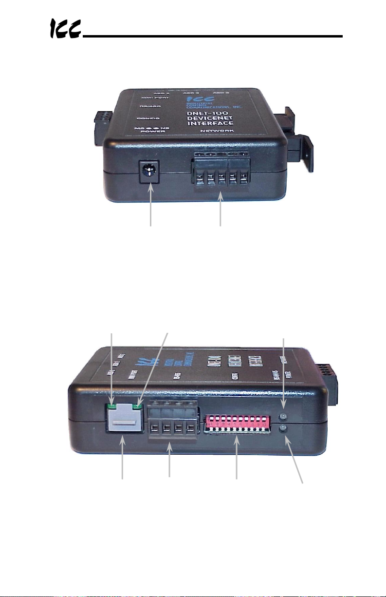
2.3 External Interface
AUX
Power
Figure 4: Bottom View
RS-485 Tx
LED
MMI
Port
RS-485 Rx
LED
Secondary
RS-485
Figure 5: Front View
DeviceNet
Network
Configuration
Switches
Network
Status LED
Module Status
LED
9
Page 11
ASD #3
Reserved
LEDs
ASD #2
Figure 6: Top View
ASD #1
ASD Link
LEDs
10
Page 12

3. Feature Summary
Primary Network
DeviceNet (5-conductor pluggable terminal block style)
Secondary Network
The DNET-100 has two physically independent secondary networks,
depending on the application:
• ASD common serial:
simultaneous connection of three Toshiba 7-series, 9-series or VFnC1 ASDs via the drives’ common serial (aka logic level)
communication ports. ASD connections use the same standard RJ45
style 8-conductor UTP patch cables: any standard CAT5 Ethernet
cable (found in most electronics stores) 5 meters or less in length can
be used to connect the DNET-100 to the drives.
• RS-485:
Power Supply
When connected to ASDs via the ASD 1 / ASD 2 / ASD 3 ports, can be either
powered directly from the attached ASDs, or from the auxiliary “POWER” input
jack. All RS-485 secondary network topologies require the use of the auxiliary
“POWER” input.
Supported Protocols
•
Primary Network
•
Secondary Network
New secondary network drivers are continuously being added, and can be
downloaded for free from the ICC web site.
DeviceNet Compatibility
Group 2 Server Only device utilizing the Predefined Master / Slave Connection
Set. Supports the Polled and COS/Cyclic I/O connections, with consumed and
produced data sizes for each connection independently selectable from 0 to
200 bytes. This product has been self-tested by ICC, Inc. and found to comply
with ODVA Conformance Test Software Version A-13.
Text-Based Console Configuration
The unit is configured via a text-based console interface, available over RS232
by using the included MMI cable and a standard PC terminal program such as
Microsoft Windows HyperTerminal®.
Half-duplex RS-485 (A / B / Signal Ground / Shield)
o
DeviceNet (per ODVA specifications)
o
Toshiba ASD (common serial)
o
Modbus RTU (RS-485)
o
Sullair Supervisor (RS-485)
The DNET-100 provides support for
11
Page 13

Point File-Based Configuration
Up to 3 point files (primary / secondary network mapping definition files) can be
stored in the unit’s internal battery-backed file system. Point files can also be
uploaded from / downloaded to a PC, which provides the capability for PCbased file backup and easy configuration copying to multiple units. Sample
point files and related documentation can also be downloaded from the ICC
web site, uploaded to a unit, and custom-modified to suit a specific application.
Drive AutoScan Algorithm
ASD common serial port connections are automatically established and
continuously monitored (when points are defined for that drive). No drive
configuration needs to be performed to connect the gateway to the drives.
Just plug it in – it’s that simple.
Network Timeout Action
A configurable network timeout selection can be programmed that allows each
DeviceNet parameter object to have its own unique “fail-safe” condition in the
event of a primary network interruption event.
Indicators
2 green LEDs exist on each of the ASD ports and on the MMI port connector.
The DNET-100 also contains bicolor DeviceNet network status (NS) and
module status (MS) LEDs. Refer to section 9 for more detailed information
about the LED indicators and their meanings.
MMI Port Connector
RS232-level. Use the DB9-to-RJ45 MMI cable supplied with the gateway kit to
interface with the unit for either console-based configuration, point file
upload/download, or flash firmware downloading.
EDS Autogenerator
The DNET-100 automatically generates a customized Electronic Data Sheet
(EDS) once configuration is complete. This EDS is then transmitted to your
computer via the Xmodem protocol for registration by network configuration
tools.
Field-Upgradeable
As new firmware becomes available, the gateway unit can be upgraded in the
field by the end-user. Refer to section 15 for more information.
Versatile 3-Way DIN-Rail Mounting System
The unit’s enclosure is provided with a mounting clip attached to the rear of the
unit. This clip allows the unit to be mounted 3 different ways:
•
For DIN rail mounting, snap the mounting clip onto a standard DIN
rail, and then snap the unit enclosure onto the clip’s retaining tabs.
This allows easy removal or repositioning of the unit on the DIN rail
during wiring.
12
Page 14

•
For panel mounting, the mounting clip can be bolted directly to a flat
panel via the two bolt holes at the top and bottom of the clip. Refer to
section 2.2 for mounting clip mechanical details. Once the mounting
clip is securely attached to the panel, the unit enclosure can be
snapped onto the clip’s retaining tabs.
•
For fixed DIN rail mounting, a combination of the above two
techniques can be employed. First, snap the mounting clip onto a
DIN rail and position it in its desired location. Then, the mounting clip
can be bolted to the DIN rail support panel, securing it in place.
Lastly, the unit can be snapped onto the fixed mounting clip.
In all cases, the unit can be easily unsnapped from the mounting clip whenever
necessary to provide easier access.
13
Page 15

4. Installing the Interface
The installation procedure of the gateway will vary slightly depending on the
chosen secondary network.
4.1 RS-485 Secondary Network
Note that in order to power the unit when using the secondary RS-485 network,
you must also purchase the optional 120VAC/9VDC power supply (ICC part
number 10456).
1. Attach the mounting clip and unit enclosure in your desired manner (refer
to page 12 for more information).
2. Connect the DeviceNet network to the 5-position “Network” terminal block.
Be sure to follow all published guidelines pertaining to DeviceNet network
connections, layout and routing. Ensure that the terminal block is fully
seated into the terminal block header, and route the network cable such
that it is located well away from any electrical noise sources, such as ASD
input power or motor wiring. Also take care to route the cable away from
any sharp edges or positions where it may be pinched.
3. Repeat step 2 above to connect the secondary network to the “Secondary
RS-485” terminal block.
4. Take a moment to verify that the gateway and all network cables have
sufficient clearance from electrical noise sources such as drives, motors,
or power-carrying electrical wiring.
5. Connect the power supply to the gateway’s “Power” jack.
14
Page 16

4.2 Toshiba ASD (Common Serial) Secondary Network
The gateway connects to each drive via the drive’s common serial (logic level)
communication port, typically located on either the main drive control board
(G7), on the front of the drive enclosure under a small snap-on cover (A7, S9),
on the right-hand side of the drive enclosure under a small snap-on cover (S7),
or on the bottom side of the drive enclosure (VF-nC1). Although in general no
drive parameters need to be configured in order to use the gateway, it is
advantageous to check that the drive’s common serial communication data
rate is set to its maximum speed. Because the gateway will communicate to
each drive only at the drive’s configured data rate, this will provide the fastest
response time for drive-to-gateway data transfers. For information on checking
the drive’s common serial communication data rate, refer to the appropriate
manual supplied with your drive.
Note that the common serial communication parameters of each drive are
handled independently by the gateway, which means that different drive
families may be connected to different channels of the unit in any combination,
and that the drives connected to each channel may simultaneously
communicate to the unit at completely different baud rates, parity settings, etc.
Drives can be connected to the gateway on any ASD channel in any order or
combination. When more than one drive is connected to the unit, or if the
optional auxiliary power supply is used, the gateway will draw its control power
from the source with the highest power supply voltage.
Installation of the gateway should only be performed by a qualified technician
familiar with the maintenance and operation of the connected drives. To install
the gateway, complete the steps outlined in the following sections related to
your specific drive.
4.2.1 Installation for G7 ASDs
1.
2.
3. Attach the mounting clip and gateway enclosure in your desired manner
CAUTION!
be connected have been turned OFF and are locked and tagged out.
DANGER!
electrolytic capacitors to discharge before proceeding to the next step.
not touch any internal parts with power applied to the drive, or for at
least 5 minutes after power to the drive has been removed. A hazard
exists temporarily for electrical shock even if the source power has
been removed.
continuing the installation process.
(refer to page 12 for more information).
Verify that all input power sources to the drives to
Wait at least 5 minutes for the drive’s
Verify that the CHARGE LED has gone out before
15
Do
Page 17

4. Remove the drive’s front cover / open the drive’s cabinet door (refer to the
appropriate drive manual for instructions how to do this).
5. The drive’s LCD panel (also called the “Electronic Operator Interface” or
“EOI”) can communicate with the drive via either the RS485/RS232
channel (CNU1/CNU1A) or the common serial channel (CNU2/CNU2A).
Because the gateway uses the common serial channel, the LCD panel
must be configured to use the RS485/RS232 channel. If the drive to be
connected is currently using CNU2 (on the drive control board) and
CNU2A (on the LCD panel), then this connection must first be switched
over to CNU1 (on the drive control board) and CNU1A (on the LCD panel).
Refer to Toshiba’s documentation for any precautions or notices regarding
this connection change. If the LCD panel is already connected via the
RS485/RS232 channel, then no change is required.
6. Configure the drive’s LCD panel to communicate via the RS485/RS232
channel by setting parameter ”
Communication Setting
Parameters.. Communication Settings.. Select LCD Port
Connection
RS485/232 serial
”.
” to “
7. Connect the drive’s common serial communication port (CNU2) to one of
the ASD channels of the gateway with the communication cable
(communication cable is not included with the gateway kit). When
choosing cables for this connection, standard 24 AWG category 5 (CAT5)
unshielded twisted-pair (UTP) 8-conductor cables found in Ethernet
networks in most office environments can be used. The maximum
allowable length for these cables is 5 meters. Although there are many
varieties and styles of CAT5 UTP cables available, ICC strongly
recommends using only high-quality cables from reputable manufacturers
to guarantee optimal noise immunity and cable longevity. Ensure that
each end of the cable is fully seated into the modular connectors, and
route the cable such that it is located well away from any drive input power
or motor wiring. Also take care to route the cable away from any sharp
edges or positions where it may be pinched.
8. Reinstall the drive’s front cover / close the drive’s cabinet door.
9. Repeat steps 1-8 to connect other drive(s) as needed.
10. Connect the DeviceNet network to the 5-position “Network” terminal block.
Be sure to follow all published guidelines pertaining to DeviceNet network
connections, layout and routing. Ensure that the terminal block is fully
seated into the terminal block header, and route the network cable such
that it is located well away from any electrical noise sources, such as ASD
input power or motor wiring. Also take care to route the cable away from
any sharp edges or positions where it may be pinched.
11. If an auxiliary power supply is going to be used, connect it to the
gateway’s “Power” jack.
12. Take a moment to verify that the gateway and all primary and secondary
network cables have sufficient clearance from drives, motors, or powercarrying electrical wiring.
16
Page 18

13. Turn the power sources to all connected drives ON, and verify that the
drives function properly. If the drives do not appear to power up, or do not
function properly, immediately turn power OFF.
remove all power from the drives.
ICC or your local Toshiba representative for assistance if the problem
persists.
Then, verify all connections. Contact
Repeat steps 1 and 2 to
4.2.2 Installation for S7, S9, A7 and VF-nC1 ASDs
1.
2.
3. Attach the mounting clip and gateway enclosure in your desired manner
4. Remove the drive’s common serial communication port cover if it has one
5. Connect the drive’s common serial communication port to one of the ASD
6. Repeat steps 1, 2, 4 and 5 to connect other drive(s) as needed.
7. Connect the DeviceNet network to the 5-position “Network” terminal block.
CAUTION!
be connected have been turned OFF and are locked and tagged out.
DANGER!
electrolytic capacitors to discharge before proceeding to the next step.
not touch any internal parts with power applied to the drive, or for at
least 5 minutes after power to the drive has been removed. A hazard
exists temporarily for electrical shock even if the source power has
been removed.
continuing the installation process.
(refer to page 12 for more information).
(refer to the appropriate drive manual for instructions how to do this). Do
not discard this cover, as it should be reinstalled to minimize
contamination of the port’s electrical contacts if the gateway is ever
disconnected from the drive.
channels of the gateway with the communication cable (communication
cable is not included with the gateway kit). When choosing cables for this
connection, standard 24 AWG category 5 (CAT5) unshielded twisted-pair
(UTP) 8-conductor cables found in Ethernet networks in most office
environments can be used. The maximum allowable length for these
cables is 5 meters. Although there are many varieties and styles of CAT5
UTP cables available, ICC strongly recommends using only high-quality
cables from reputable manufacturers to guarantee optimal noise immunity
and cable longevity. Ensure that each end of the cable is fully seated into
the modular connectors, and route the cable such that it is located well
away from any drive input power or motor wiring. Also take care to route
the cable away from any sharp edges or positions where it may be
pinched.
Be sure to follow all published guidelines pertaining to DeviceNet network
connections, layout and routing. Ensure that the terminal block is fully
Verify that all input power sources to the drives to
Wait at least 5 minutes for the drive’s
Do
Verify that the CHARGE LED has gone out before
17
Page 19

seated into the terminal block header, and route the network cable such
that it is located well away from any electrical noise sources, such as ASD
input power or motor wiring. Also take care to route the cable away from
any sharp edges or positions where it may be pinched.
8. If an auxiliary power supply is going to be used, connect it to the
gateway’s “Power” jack.
9. Take a moment to verify that the gateway and all primary and secondary
network cables have sufficient clearance from drives, motors, or powercarrying electrical wiring.
10. Turn the power sources to all connected drives ON, and verify that the
drives function properly. If the drives do not appear to power up, or do not
function properly, immediately turn power OFF.
remove all power from the drives.
Then, verify all connections. Contact
Repeat steps 1 and 2 to
ICC or your local Toshiba representative for assistance if the problem
persists.
18
Page 20
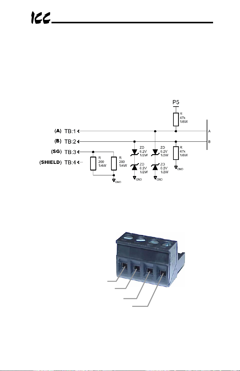
A
5. RS-485 Electrical Interface
In order to ensure appropriate network conditions (signal voltage levels, etc.),
some knowledge of the gateway’s RS-485 network interface circuitry is
required. Refer to Figure 7 for a simplified network schematic of the secondary
RS-485 interface circuitry. Note that the “Shield” terminal has no internal
connection: its purpose is simply to provide a cable shield chaining location
between devices. The shield is then typically connected to ground at one
location only.
Figure 7: RS-485 Interface Circuitry Schematic
Figure 8 details the specific network connections to the RS-485 terminal block.
B
Signal Ground
Shield
Figure 8: RS-485 Terminal Block Connections
19
Page 21

6. Environmental Specifications
Item Specification
Indoors, less than 1000m above sea level, do not
Operating Environment
expose to direct sunlight or corrosive / explosive
gasses
Operating Temperature
Storage Temperature
Relative Humidity
Vibration
Main Circuit Grounding Non-isolated, referenced to power source ground
DeviceNet Grounding Isolated, referenced to DeviceNet network power
Cooling Method Self-cooled
∼
+50°C (+14 ∼ +122°F)
-10
∼
+85°C (-40 ∼ +185°F)
-40
∼
90% (without condensation)
20%
2
5.9m/s
{0.6G} or less (10 ∼ 55Hz)
20
Page 22

7. Maintenance and Inspection
Preventive maintenance and inspection is required to maintain the gateway in
its optimal condition, and to ensure a long operational lifetime. Depending on
usage and operating conditions, perform a periodic inspection once every
three to six months. Before starting inspections, disconnect all power sources
(with ASD connections, turn off all power supplies to connected drives and wait
at least five minutes after each drive’s “CHARGE” lamp has gone out.)
Inspection Points
•
Check that the dust covers for all unused RJ45 ports are seated firmly in
their connectors.
•
If applicable, check that the ASD communication cables are fully seated in
both the drive and gateway RJ45 ports. Reseat if necessary.
•
Check that the network cable(s) are properly terminated in the terminal
block(s), and ensure that pluggable terminal blocks are fully seated in their
headers. Reseat if necessary.
•
Check that there are no defects in any attached wire terminal crimp points.
Visually check that the crimp points are not scarred by overheating.
•
Visually check all wiring and cables for damage. Replace as necessary.
•
Clean off any accumulated dust and dirt.
•
If use of the gateway is discontinued for extended periods of time, apply
power at least once every two years and confirm that the unit still functions
properly.
•
Do not perform hi-pot tests on the gateway, as they may damage the unit.
Please pay close attention to all periodic inspection points and maintain a good
operating environment.
21
Page 23

8. Storage and Warranty
8.1 Storage
Observe the following points when the gateway is not used immediately after
purchase or when it is not used for an extended period of time.
•
Avoid storing the unit in places that are hot or humid, or that contain large
quantities of dust or metallic dust. Store the unit in a well-ventilated
location.
•
When not using the unit for an extended period of time, apply power at
least once every two years and confirm that it still functions properly.
8.2 Warranty
The gateway is covered under warranty by ICC, Inc. for a period of 12 months
from the date of installation, but not to exceed 18 months from the date of
shipment from the factory. For further warranty or service information, please
contact Industrial Control Communications, Inc. or your local distributor.
22
Page 24

9. LED Indicators
The gateway contains several different LED indicators, each of which conveys
important information about the status of the unit and connected networks.
These LEDs and their functions are summarized here.
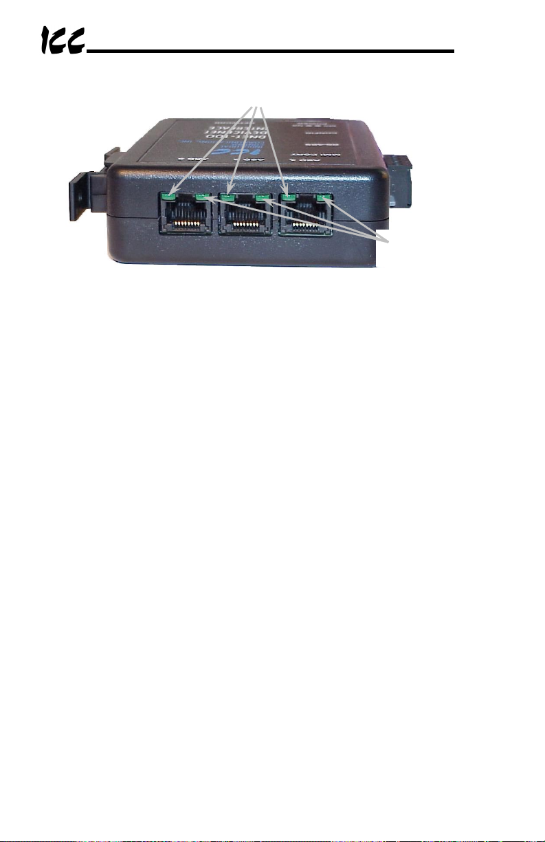
9.1 ASD Port Indicators
Each ASD port RJ45 connector contains two integrated green LEDs. Figure 9
indicates the functions of these LEDs.
Reserved
Functionality is currently
reserved (LED will always
be OFF during operation)
Drive Link
Solid green when a logical
connection exists with the
attached drive
Figure 9: Drive Connector Indicators
The Drive Link indicator provides an easy method of determining that the
gateway and drive are successfully exchanging data, independent of primary
network activity (Note: Drive Link LED will be OFF if no points are defined for
that channel, even if a drive is physically connected to the port).
23
Page 25

9.2 MMI Port Indicators
The MMI port RJ45 connector also contains two integrated green LEDs.
Figure 10 indicates the functions of these LEDs.
RS-485 Transmit Indicator
Blinks in 0.1s-long bursts when
secondary RS-485 network
requests are being transmitted
by the gateway
RS-485 Receive Indicator
Blinks in 0.1s-long bursts when
secondary RS-485 network
responses are being received
by the gateway
Figure 10: MMI Port Indicators
9.3 DeviceNet Indicators
The standard bicolor DeviceNet Module Status (MS) and Network Status (NS)
LEDs are supported as indicated in Figure 11. Behavior is as specified in the
ODVA DeviceNet Specifications.
Network Status (NS)
Indicates state of the DeviceNet
network as defined in the
DeviceNet Specifications
Module Status (MS)
Indicates state of the module as
defined in the DeviceNet
Specificatio ns
Figure 11: DeviceNet Indicators
24
Page 26

10. Configuration Switches
There are ten configuration DIP switches located on the front side of the
gateway. Switches #1 - #6 set the DeviceNet MAC ID of the gateway (refer to
Table 1).
Table 1: DeviceNet MAC ID Assignment
SW1 SW2 SW3 SW4 SW5 SW6
OFF OFF OFF OFF OFF OFF 0 OFF OFF OFF OFF OFF ON 32
ON OFF OFF OFF OFF OFF 1 ON OFF OFF OFF OFF ON 33
OFF ON OFF OFF OFF OFF 2 OFF ON OFF OFF OFF ON 34
ON ON OFF OFF OFF OFF 3 ON ON OFF OFF OFF ON 35
OFF OFF ON OFF OFF OFF 4 OFF OFF ON OFF OFF ON 36
ON OFF ON OFF OFF OFF 5 ON OFF ON OFF OFF ON 37
OFF ON ON OFF OFF OFF 6 OFF ON ON OFF OFF ON 38
ON ON ON OFF OFF OFF 7 ON ON ON OFF OFF ON 39
OFF OFF OFF ON OFF OFF 8 OFF OFF OFF ON OFF ON 40
ON OFF OFF ON OFF OFF 9 ON OFF OFF ON OFF ON 41
OFF ON OFF ON OFF OFF 10 OFF ON OFF ON OFF ON 42
ON ON OFF ON OFF OFF 11 ON ON OFF ON OFF ON 43
OFF OFF ON ON OFF OFF 12 OFF OFF ON ON OFF ON 44
ON OFF ON ON OFF OFF 13 ON OFF ON ON OFF ON 45
OFF ON ON ON OFF OFF 14 OFF ON ON ON OFF ON 46
ON ON ON ON OFF OFF 15 ON ON ON ON OFF ON 47
OFF OFF OFF OFF ON OFF 16 OFF OFF OFF OFF ON ON 48
ON OFF OFF OFF ON OFF 17 ON OFF OFF OFF ON ON 49
OFF ON OFF OFF ON OFF 18 OFF ON OFF OFF ON ON 50
ON ON OFF OFF ON OFF 19 ON ON OFF OFF ON ON 51
OFF OFF ON OFF ON OFF 20 OFF OFF ON OFF ON ON 52
ON OFF ON OFF ON OFF 21 ON OFF ON OFF ON ON 53
OFF ON ON OFF ON OFF 22 OFF ON ON OFF ON ON 54
ON ON ON OFF ON OFF 23 ON ON ON OFF ON ON 55
OFF OFF OFF ON ON OFF 24 OFF OFF OFF ON ON ON 56
ON OFF OFF ON ON OFF 25 ON OFF OFF ON ON ON 57
OFF ON OFF ON ON OFF 26 OFF ON OFF ON ON ON 58
ON ON OFF ON ON OFF 27 ON ON OFF ON ON ON 59
OFF OFF ON ON ON OFF 28 OFF OFF ON ON ON ON 60
ON OFF ON ON ON OFF 29 ON OFF ON ON ON ON 61
OFF ON ON ON ON OFF 30 OFF ON ON ON ON ON 62
ON ON ON ON ON OFF 31 ON ON ON ON ON ON 63
MAC
SW1 SW2 SW3 SW4 SW5 SW6
ID
MAC
ID
25
Page 27

Switches #7 and #8 are used to set the DeviceNet network baud rate as
indicated in Table 2.
Table 2: DeviceNet Network Baud Rate Selection
SW7 SW8 Network Baud Rate
OFF OFF 125 kbps
ON OFF 250 kbps
OFF ON
ON ON
Switch #9 is currently reserved, and switch #10 is used during flash firmware
reprogramming of the gateway (refer to section 15).
Note that the “ON” position of each switch is the “down” position and that the
“OFF” position is the “up” position. Refer to the indicator markings on the
switch.
The MAC ID and configured baud rate are read by the DNET-100 only on
power-up or after a reset. Therefore, if either of these selections is changed
be sure to either power the unit off momentarily by disconnecting it from all
power sources, or perform a soft reset on the unit by entering and then exiting
the configuration console or by issuing a RESET service to the Identity Object.
500 kbps
11. Internal Battery
The gateway has an internal coin-cell type battery that is used to backup the
file system and maintain the real-time clock when the gateway is unpowered.
This battery is designed to last the lifetime of the product under normal use.
However, if the gateway is left unpowered for several years, the battery may
become exhausted. For this reason, always be certain to download any
customized point files to a PC so that they will be available for uploading again
if the battery fails and requires replacement.
If the battery becomes discharged, contact ICC for assistance in obtaining a
replacement. Alternatively, it can be replaced by the user by removing all
power sources from the gateway, opening the case, carefully popping out the
discharged battery and replacing it with a Panasonic BR1632 or equivalent
component.
26
Page 28

12. Point Configuration
As mentioned in section 1, the Network Gateway Series concept revolves
around a central “point database”, containing various individual points. A
“point” is simply an object that defines some sort of primary -to- secondary
network mapping information. In the case of the DNET-100, a point is simply a
DeviceNet parameter object, whose characteristics (attributes) are entered by
the user via the serial console. Throughout the remainder of this manual,
therefore, configured points may also be referenced by their more naturallyassociated terms “parameters”, “parameter objects”, or “DeviceNet
parameters”. Up to a total of 100 individual parameters can be defined, and
they can be allocated as necessary to any secondary-network device and
contained data item.
The information that must be entered by the user to define the characteristics
of a parameter can be divided into two subsets: that information required to
map parameter objects to their appropriate secondary-network device and
contained data item, and that information required to conveniently define and
access the parameter via the DeviceNet network (i.e. to generate an Electronic
Data Sheet (EDS) and access the parameter via a network configuration tool,
such as Rockwell Software’s
The required mapping information includes the secondary-network device’s
station number (or ASD port number in the case of an ASD common serial
secondary network), the secondary network data item (register number,
parameter number etc.) residing in that device, and the DeviceNet parameter
object instance (or “parameter number”). The mapping information is required
to provide access to the targeted secondary network data item when the
parameter is accessed via explicit messaging, or when the parameter is
included in one of the available I/O assembly objects and accessed via the
polled or COS/cyclic I/O connections.
The parameter definition information includes such items as the parameter’s
data type, name, help string, minimum, maximum and default values, scaling
factors and decimal precision. Considerations are also included to provide a
parameter-specific timeout value to be written to the parameter’s associated
secondary network object in the event of a DeviceNet network timeout. In
general, parameter definition information has no bearing on the normal
operation of the gateway (i.e. communication with a scanner or other master
device): it exists only to create a customized EDS when configuration is
complete, and to be used by a network configuration tool to facilitate proper
data display and entry methods when accessed via the explicit messaging
connection.
RSNetWorx For DeviceNet
).
27
Page 29

12.1 Parameter Configuration
As previously mentioned, each data item residing on secondary-network
devices must be mapped to a unique DeviceNet parameter object to allow
access via the DeviceNet network. This access may take place directly via
explicit messaging, or indirectly via I/O messaging. These secondary-network
data items are collectively referred to as
constitutes an object varies depending on the secondary-network protocols
and devices involved. For example, an object on a Modbus RTU secondary
network is simply a Modbus holding register, and on a Toshiba ASD secondary
network is a drive parameter (configuration parameters, control parameters
and status parameters are all handled the same by the gateway). Once the
mapping is performed, the DeviceNet master or configuration tool can access
the secondary-network object by simply accessing (typically via explicit
messaging for a configuration tool and via I/O messaging for a scanner) the
configured DeviceNet parameter.
This can perhaps best be demonstrated by use of an example. Say, for
instance, that a DeviceNet configuration tool (such as
DeviceNet
) would like to gain access to four Modbus RTU devices. The
Modbus devices have been pre-assigned the addresses 5, 7, 9 and 11. This
system is represented in Figure 12.
objects
. The definition of what
RSNetWorx For
Config
Tool
DeviceNet
Network
Gateway
Secondary
Network
Address
5
Address
9
Modbus
Devices
Address
7
Address
11
Figure 12: Example System
28
Page 30

In order to allow the tool to access the Modbus devices, we must define a
DeviceNet parameter for each of the objects (secondary network Modbus
registers) that we wish to access. Let’s assume that the data shown in Table 3
is to be accessed on each of the respective Modbus devices, and that the
data’s characteristics are as indicated.
Table 3: Example Secondary-Network Data
Modbus Address Modbus Register Note
5 10 Frequency command (1=0.01Hz)
“ 15 Operating frequency (1=0.01Hz)
“ 120 Run/Stop command (run=0x0080)
“ 125 Run/Stop status (running=0x0080)
7 2 Temperature sensor (1=0.1C)
“ 4 Digital output (ON=0x0001)
9 8 Voltage monitor #1 (1=1v)
“ 9 Voltage monitor #2 (1=1v)
“ 10 Voltage monitor #3 (1=1v)
11 8 Voltage monitor #1 (1=1v)
“ 9 Voltage monitor #2 (1=1v)
“ 10 Voltage monitor #3 (1=1v)
From this table we notice that in total 12 DeviceNet parameters must be
created (one for each Modbus register to be accessed). By definition,
DeviceNet parameter numbers start at 1, sequentially increasing thereafter.
For the time being, we will ignore the additional gateway configuration required
to assign these parameters to be members of I/O assembly objects, and focus
simply on their existence and access via a configuration tool. Let’s begin by
creating our first DeviceNet parameter, which will map to Modbus register 10
(“frequency command”) on Modbus address 5. Via the DNET-100’s console,
we can add a new point, and configure it as follows:
DeviceNet parameter............................ 1 (automatically assigned)
Modbus RTU ID.................................... 5
Modbus RTU register number .............. 10
Name string .......................................... “Freq command”
Help string ............................................“FC command value”
Units string............................................ “Hz”
Data Type ............................................. UINT
Read Only............................................. N
Max Value............................................. 8000
Min Value.............................................. 0
Default Enable ...................................... N
Default Value ........................................ 0
Allow Scaling ........................................ Y
Multiplier ............................................... 1
Divisor................................................... 100
Offset .................................................... 0
Precision............................................... 2
29
Page 31

Don’t worry if you don’t understand the meanings of all of the fields listed
above at this point: their significance will be explained in detail later during the
console configuration portion of this manual. In a similar fashion to parameter
#1, we can enter the remainder of the parameters (#2 - #12) to correspond to
the secondary network architecture provided in Table 3.
While the mapping function provided by configured parameters may be
obvious, there is another less-apparent service that they also provide. This
service is termed
data mirroring
, whereby current copies of secondary
network object values are maintained locally within the gateway itself. This
greatly reduces the primary network’s request-to-response latency time, as
read and write requests can be entirely serviced locally, thereby eliminating the
time required to execute a secondary network transaction.
Another advantage afforded by the ability to map secondary network objects to
any available DeviceNet parameter number is the capability of
reorganization
. Data reorganization allows the grouping of secondary
data
network objects into more logical or efficient patterns. Because the DeviceNet
network tool or scanner never “sees” the true secondary network addresses or
object indexes (i.e. register numbers), the secondary network address/object
assignment can be determined by any user-defined criteria (physical unit
position on the floors of a building, for example), while allowing the DeviceNet
parameter assignments to be chosen using a different criteria (grouping
according to device application or function, for example). For instance, if three
ASDs were connected to a DNET-100 gateway, parameters #1, #2 and #3
could be assigned as the frequency commands of ASD #1, ASD #2 and ASD
#3, respectively.
Once the attributes of each parameter have been entered, the final results of
the overall assignment are given in Table 4. The information residing on the
Modbus devices can now be accessed via standard DeviceNet parameter
access methods.
Table 4: Final Parameter Assignment Example
DeviceNet
Parameter
Modbus Address/
Register
Note
1 5 / 10 Frequency command
2 5 / 15 Operating frequency
3 5 / 120 Run/Stop command
4 5 / 125 Run/Stop status
5 7 / 2 Temperature sensor
6 7 / 4 Digital output
7 9 / 8 Voltage monitor #1
8 9 / 9 Voltage monitor #2
9 9 / 10 Voltage monitor #3
10 11 / 8 Voltage monitor #1
11 11 / 9 Voltage monitor #2
12 11 / 10 Voltage monitor #3
30
Page 32

12.2 I/O Assemblies
Now that we have been exposed to the concepts of parameter mapping and
access, let’s further expand upon this concept to include the configuration of
I/O assemblies. The DNET-100 supports four I/O assembly objects, whose
instance numbers are defined as follows:
Polled I/O output assembly............................ instance #100 (0x64)
Polled I/O input assembly.............................. instance #150 (0x96)
COS/cyclic I/O output assembly.................... instance #101 (0x65)
COS/cyclic I/O input assembly ......................instance #151 (0x97)
The sizes and member lists of these assembly objects are entirely userconfigurable, and the configuration of each assembly object is independent of
the others. The assembly sizes (consumed data for output assemblies and
produced data for input assemblies) are selectable from 0 to 200 bytes, in 2byte increments. The reason for the 2-byte increment restriction is due to the
fact that all secondary-network data object values for protocols supported by
the DNET-100 are 16 bits in size. Any valid DeviceNet parameter currently
defined in the gateway can be included in the member list of any of the I/O
assemblies.
To see how this works, we will continue our example network that we started in
the previous section. Now, however, we are interested in adding DeviceNet
scanner access to the 12 parameters that we previously defined. First, we
need to determine which parameters are command-oriented (parameters that
we will write to with the intent on performing some action) and which are
status-oriented (parameters that we will monitor with the intent of determining a
data object’s status). From Table 4, we can see that parameters 1, 3 and 6
are command-oriented, and the rest are status-oriented.
Our next decision is to determine which I/O assemblies we will use (poll, COS,
cyclic, poll+COS or poll+cyclic). This decision is typically based on the specific
nature of each application, and must be determined by the person performing
the network configuration. For this example, we will use Polled I/O only, and
will therefore only need to configure the characteristics of assembly instances
100 and 150.
To determine the required sizes of the I/O assembly instances, we can
recognize the fact that the “value” attributes of all DNET-100 parameters are
16 bits (2 bytes) in length. This results in the following formula:
Number of parameters in member list x 2 = size of assembly in bytes
For assembly instance 100 (our command assembly), therefore, we can use
the above equation with our previous determination of having 3 commandoriented parameters to arrive at a consumed data size of 6 bytes. Similarly,
the produced data size for assembly instance 150 can be calculated to be 18
bytes. These size definitions are then entered into the DNET-100’s console.
Note that in this example we have chosen to include all available parameters
31
Page 33

as members of I/O assemblies. There is no requirement to do this, however: it
is perfectly acceptable to define a stand-alone parameter which is not a
member of any assembly object definition, and is therefore only accessible via
normal parameter object access methods (i.e. explicit messaging).
Note that during I/O data exchanges, if the actual consumed data size is less
than or equal to a connection instance’s configured consumed connection size,
then all received data will be consumed and the connection will produce
normally. If the actual consumed data size is larger than the connection
instance’s configured consumed connection size, however, the consumed data
will be ignored and the connection will not produce.
The last I/O assembly configuration detail requiring discussion is the member
list definitions and the assignment of the offsets within each assembly
instance. Each assembly instance can be viewed as a contiguous array of
bytes, the size of which is dependent on the number of constituent member
parameters (6 bytes and 18 bytes, respectively, in our example). Including a
parameter in an assembly member list allows us to access that parameter via
I/O messaging, and is simply a function of assigning the parameter number to
an offset (an assembly object array starting position). Because all parameters
are 16-bit values, valid offsets range from 0, 2, 4...198. For example, after
defining our consumed data size for assembly instance 100 to be 6 bytes, the
initial (default) member list and related offset assignments will be as shown in
Table 5.
Table 5: Initial Example Assembly Instance Definition (Instance 100)
Offset Member Parameter Note
0 N/A
1
2 N/A
3
4 N/A
5
0
0
0
N/A
N/A
N/A
Note that the member parameter for each offset group is 0, which means “not
assigned”. If a 0 exists in an output (command) assembly member list, then
the consumed data in that position will be ignored. If a 0 exists in an input
(status) assembly member list, then the produced data in that position will
always be “0”.
For simplicity, we will assign our command-oriented parameters 1, 3 and 6 to
reside at output assembly instance offsets 0, 2 and 4, respectively. Any
arrangement of these three parameters within the three available member list
positions would be valid, however. After making these member list
assignments, the initial assembly object data array given in Table 5 is then
updated as indicated in Table 6 below:
32
Page 34

Table 6: Final Example Assembly Instance Definition (Instance 100)
Offset Member Parameter Note
0 Frequency command LO byte
1
2 Run/Stop command LO byte
3
4 Digital output LO byte
5
1
3
6
Frequency command HI byte
Run/Stop command HI byte
Digital output HI byte
In a similar way, we can define the member list of the 18-byte long produced
data array for input (status) assembly instance 150 as indicated in Table 7.
Table 7: Final Example Assembly Instance Definition (Instance 150)
Offset Member Parameter Note
0 Operating frequency LO byte
1
2 Run/Stop status LO byte
3
4 Temperature sensor LO byte
5
6 Voltage monitor #1 LO byte
7
8 Voltage monitor #2 LO byte
9
10 Voltage monitor #3 LO byte
11
12 Voltage monitor #1 LO byte
13
14 Voltage monitor #2 LO byte
15
16 Voltage monitor #3 LO byte
17
2
4
5
7
8
9
10
11
12
Operating frequency HI byte
Run/Stop status HI byte
Temperature sensor HI byte
Voltage monitor #1 HI byte
Voltage monitor #2 HI byte
Voltage monitor #3 HI byte
Voltage monitor #1 HI byte
Voltage monitor #2 HI byte
Voltage monitor #3 HI byte
Once this configuration is complete, we will be able to send command
information to, and read status information from, the Modbus devices residing
on the DNET-100’s secondary network. If desired, we could have also chosen
to utilize the COS/cyclic I/O connection, either instead of the polled I/O
connection or in conjunction with it. In some instances, it may be convenient
to assign different parameters to the polled and COS/cyclic assembly
definitions, and then allocate both connections via the network master. This
combination is useful when a master wants to poll the device for some inputs
every scan cycle, and receive different inputs (such as slowly-changing
temperatures, for example) at a slower rate via the COS/cyclic connection.
33
Page 35

12.3 Network Timeout Settings
The gateway can be configured to perform a specific set of actions when
DeviceNet communications are lost. A loss of DeviceNet communications can
be due to several different events, such as a connection timer (expected
packet rate) time-out, a CAN busoff event, or loss of DeviceNet network power.
During the parameter definition phase of the DNET-100’s configuration, the
user is prompted for a “Default Enable” selection. The default value of this
selection is “N”, in which case the parameter being defined does not have the
ability to participate in timeout processing. If the user enters “Y”, however, the
“Default Value” attribute of the parameter being configured serves a dual
purpose. While it is still used to generate the “default value” field in the EDS,
this default value will also be used as the timeout value that can optionally be
written to the parameter in the event of a DeviceNet network timeout.
The item which determines when and how “default value” timeout processing
will take place is the “Timeout Mode” selection found in the DNET-100’s Main
Menu > Points > DeviceNet Setup menu. Possible values for the Timeout
Mode parameter are 0-3, with the following meanings:
0 ......Take no action (ignore the timeout). A network timeout will not result in
any parameter value modification.
1 ......Write the Default Values to those points that are members of the polled
I/O output assembly that have their Default Enable attributes set to “Y”.
For example, if parameter object #1 has its Default Enable set to “Y”, its
Default Value set to 10, the Timeout Mode is set to 1, and parameter #1
is a member of the polled I/O output assembly object definition
(assembly instance 100), then when a network timeout occurs, a value of
10 will be written to the secondary-network data object defined in
parameter object #1’s configuration.
2 ......Write the Default Values to those points that are members of the
COS/cyclic IO output assembly that have their Default Enable attributes
set to “Y”. This is similar to setting “1” above, except that it affects only
those parameters that are members of the COS/cyclic I/O output
assembly object definition (assembly instance 101).
3 ......Write the Default Values to all points that have their Default Enable
attributes set to “Y”. This setting is independent of a parameter’s
membership in any assembly instances.
Note that Timeout Mode settings 1 and 2 above affect those parameters that
are simply defined to be members of assembly instances 100 and 101,
respectively. Whether or not the given assembly instance is in use at the
moment the timeout occurs is irrelevant. For example, if parameter object #1
has its Default Enable set to “Y”, its Default Value set to 10, and it is a member
of the polled I/O output assembly object definition (assembly instance 100),
then if the Timeout Mode is set to 1, it does not matter whether the polled I/O
connection or COS/cyclic connection (or neither) was allocated at the moment
of network timeout: parameter object #1 will still be written with its Default
34
Page 36

Value, while those parameter objects that are exclusively members of
assembly instance 101 (the COS/cyclic output assembly) will not receive
timeout processing regardless of their Default Enable settings.
This combination of parameter-specific Default Enable and global Timeout
Mode settings allow a relatively complex and specific set of “fail-safe”
behaviors to take place when unexpected failure of the DeviceNet network
occurs.
12.4 General Configuration Procedure
Now that we have had a brief tutorial on parameter and assembly object
assignment and configuration, we can summarize the general overall gateway
configuration process as follows:
1. Enter the console (stops all network communication tasks)
2. Define secondary serial communication settings (physical layer,
protocol and network characteristics)
3. Create DeviceNet parameter objects
4. Assign parameter object memberships to the I/O assembly instances
5. Save the newly-created point database to the gateway’s file system,
and download a copy to your PC for backup purposes
6. Download the customized EDS file for registration in your network
configuration tool
7. Exit the console (resets the gateway)
Of course, it is possible to simplify or even eliminate some of these steps by
starting your configuration from a pre-existing point database file (either
previously-created or downloaded from the internet), and then simply
modifying those elements necessary to match your application.
35
Page 37

13. Console Access
As mentioned in section 1, the gateway’s functionality is entirely controlled by a
“point database” that is user-modifiable. The method of accessing this
database is via a text-based console interface over an RS232 connection to a
computer’s serial (COM) port. This connection is performed by using the
included DB9-RJ45 cable to connect the gateway’s MMI port to the computer’s
serial port.
13.1 Requirements
All that is needed is a computer with a standard serial (COM) port, some sort
of communications software (such as HyperTerminal, included with Microsoft
Windows operating systems), and the included MMI cable (ICC part number
10425). Any communications software and PC will work, provided they
support ASCII communications at 38.4kbaud.
13.2 Connection
The gateway ships from the factory with a dust cover installed in the MMI port.
To minimize contamination of the port’s electrical contacts, keep this dust
cover in place whenever the MMI port is not in use.
Connect the RJ45 end of the MMI cable to the MMI port, and connect the other
end to the computer’s serial port. Ensure that the gateway has a power source
connected to it.
13.3 Application Configuration
As previously mentioned, any PC communication software and PC serial port
can be used. The software configuration example given here will be for
Windows HyperTerminal communicating via COM1.
Figure 13 shows the “Connect To” tab of the properties window for COM1.
Figure 14 shows the window that appears when “Configure” is selected in the
“Connect To” tab. Figure 15 shows the “Settings” tab of the properties window.
Most of these settings are their default values: usually the only changes
needed are the “Bits per second” and possibly “Flow control” settings shown in
Figure 14.
36
Page 38

Figure 13: HyperTerminal Configuration Screen #1
Figure 14: HyperTerminal Configuration Screen #2
37
Page 39

Figure 15: HyperTerminal Configuration Screen #3
38
Page 40

13.4 Invocation
The console provides standard access and editing methods for the various
configuration items (points and their associated attributes). It is important to
note that unless otherwise indicated, any modifications made to the point
database will become effective immediately. However, these changes will only
be permanently retained when the current database is saved to a file location:
if a change is made to the database and then the gateway is reset without
saving those changes, then the active file will be restored upon initialization,
overwriting the unsaved changes.
To enter the console, simply type “
then be notified that all communication tasks will be terminated for the duration
of the editing (refer to Figure 16). It is important to ensure that all connected
devices are in a safe state such that loss of communications will not pose a
danger to equipment or personnel. Exiting the console will reset the gateway
and restart network communications using the currently-active database file.
At most console prompt locations, typing “
menu, and typing “
console commands are not case-sensitive.
menu
” will return you to the main menu. Also note that
menu
” and press the Enter key. You will
x
” will return you to the previous
Figure 16: Starting the Console
39
Page 41

13.5 Main Menu
The main menu is shown in Figure 17. All gateway configuration is performed
by “drilling down” into progressively lower-level menus.
Figure 17: Console Main Menu
All navigation and data entry commands are input by simply entering the menu
selection number to the right of the “
fields at the console prompt. In Figure 17, for example, entering the menu
selection number “
Points submenu. Throughout this manual, example console entry strings will
be provided enclosed in quotation marks to delineate them from the
description text: whenever actually entering the console strings, however, do
not include the quotation marks.
When additional data fields are required with a data entry command, they will
be indicated by square brackets (“
data entry commands and data fields must be separated by spaces. Because
data entry commands and data fields are delineated by spaces, they are
therefore not allowed within data fields (such as name strings). In these
cases, it is usually convenient to use an underscore “_” in place of a space.
For example, attempting to enter a point’s name as “ASD1 output freq” would
result in an error, but “ASD1_output_freq” would be perfectly acceptable.
1
” (without the quotation marks) will bring up the View/Edit
>
” symbol along with any required data
[…]
”) after the menu selection number. All
40
Page 42

13.5.1 View/Edit Points
Main menu selection number 1 displays a screen which shows a summary of
the current point (parameter) configuration (see Figure 18). This screen only
displays the point mapping information: in order to access a point’s DeviceNet
definition information, menu selection number 1 “View/Edit a Point” must be
entered with the additional argument of the targeted point number.
Figure 18: View/Edit Points
13.5.1.1 View/Edit a Point
Entering “1” with a point number (such as “
Figure 18) at the View/Edit Points
point’s mapping and DeviceNet definition information. Refer to Figure 19 for
an example. Although the number of menu selections in this submenu will
remain consistent, the semantics of the first menu selection (the point mapping
information) will vary slightly depending on the currently-defined secondary
network. For example, if a Modbus secondary network is currently selected,
then the first menu selection will display something to the effect of “
RTU Reg = ID1, 1
Modbus slave ID1, holding register 1.
Whenever a new point is created (refer to section 13.5.1.2), all of the point
configuration information is set to default values. One must therefore navigate
to the View/Edit a Point
DeviceNet configuration information.
”, which indicates that the current point is mapped to
submenu for that point in order to modify the
submenu will display and allow editing of the
41
1 1
”, as shown at the bottom of
Modbus
Page 43

Figure 19: View/Edit a Point
Mapping Information:
Line 1 indicates the current point mapping information.
In Figure 19, it can be seen that DeviceNet Parameter 1 maps to ASD1,
parameter FD00 (the ASD’s output frequency). To change the mapping
information, enter menu selection number 1 with the additional arguments of
the device on which the data object resides and the data object index. For
example, the bottom of Figure 19 shows an example of changing DeviceNet
parameter 1’s mapping to ASD2 (the device on which the data object resides),
ASD parameter FD00 (the data object index). Again, the semantics of the
menu prompt and mapping modification entry string will vary depending on the
secondary network. A similar line 1 menu prompt when a Modbus secondary
network is chosen would be displayed as “
> 1 [ID num] [reg num]
”, and
its corresponding mapping modification entry string would therefore be
something to the effect of “
1 3 5
”, which would map the currently-selected
DeviceNet parameter to Modbus device ID #3, holding register #5.
Note that the entry and display radix of the secondary network data object
depends on the chosen secondary network. For example, entering a “param
num” of 10 when the Toshiba ASD secondary network is selected will map the
DeviceNet parameter to ASD parameter 0x10 (16
). However, entering a “reg
10
num” of 10 when the Modbus secondary network is selected will map the
DeviceNet parameter to holding register 10
(0x0A). These radices are
10
chosen based on the “natural radix” defined for each secondary-network
protocol. For more information on the natural radices of the available
secondary networks, refer to section 14.2.
Name:
Enter menu selection number 2 with a 16-character (max) string for the
parameter’s name. This field is used only for EDS file generation. If more than
42
Page 44

16 characters are entered, truncation will take place. An example of entering a
name would be “
2 ASD1_output_freq
”.
Help:
Enter menu selection number 3 with a 24-character (max) string for the
parameter’s help string. This field is used only for EDS file generation. If more
than 24 characters are entered, truncation will take place. An example of
entering a help string would be “3
The_operating_frequency
”.
Units:
Enter menu selection number 4 with a four-character (max) string for
the parameter’s engineering units string. This field is used only for EDS file
generation. If more than four characters are entered, truncation will take
place. An example of entering a units string of “%” would be “4 %”.
Data Type:
Enter menu selection number 5 with the chosen data type for the
parameter’s raw data. This field is used only for EDS file generation. Three
data types are supported: INT (-32768 ~ 32767), UINT (0 ~ 65535) and WORD
(bit string – 16 bits). An example of entering a data type would be “
5 uint
”.
Read Only:
Enter menu selection number 6 with the designation of whether or
not this parameter is read only (i.e. a status parameter). This field is used only
for EDS file generation. An example of designating a parameter to be
read/write capable would be “
6 N
”.
Max Value:
Enter menu selection number 7 with the maximum parameter
value. Note that this value must be within the allowable range of the selected
data type. For parameters of type WORD, this value should be set to 65535
(0xFFFF). An example of entering a maximum value of 40000 for a parameter
of type UINT would be “
7 40000
”.
Min Value:
Enter menu selection number 8 with the minimum parameter
value. Note that this value must be within the allowable range of the selected
data type. For parameters of type WORD, this value should be set to 0. An
example of entering a minimum value of -10 for a parameter of type INT would
be “8
-10
”.
Default Enable:
Enter menu selection number 9 with the designation of
whether or not this parameter has its Default Value enabled as its network
timeout value. Refer to section 12.3 for a detailed explanation of network
timeout settings. An example of disabling this parameter’s timeout processing
capabilities would be “
9 N
”.
Default Value:
Enter menu selection number 10 with the default parameter
value. If this parameter’s Default Enable selection is set to “Y”, then the
default value also doubles as this parameter’s timeout value, otherwise this
field is used only for EDS file generation. Refer to section 12.3 for a detailed
explanation of network timeout settings. An example of entering a default
value of 1000 would be “
10 1000
”.
Allow Scaling:
Enter menu selection number 11 with the designation of
whether or not this parameter should be presented to the user in its
engineering value. This field is used only for EDS file generation. If scaling is
43
Page 45

allowed, then network configuration tools such as
RSNetWorx
will typically
calculate the engineering value via Equation 1:
ValuegEngineerin
= (
+
Divisor
Multiplier x Offset) Value(Actual
Equation 1
)
The engineering value can then be displayed to the user in the terms specified
within the Precision (menu selection number 15). For example, if a DeviceNet
parameter maps to an adjustable speed drive’s frequency command value,
where an actual value of 0 ~ 6000 represents 0.00Hz ~ 60.00Hz, then typical
scaling values for use in Equation 1 would be:
Offset........... 0
Multiplier...... 1
Divisor ......... 100
Precision ..... 2
11 Y
An example of allowing scaling would be “
”.
Multiplier:
Enter menu selection number 12 with a multiplier value. Valid
values are 0 ~ 65535. This field is used only for EDS file generation. For
typical application of the multiplier value, refer to Equation 1. An example of
12 1
setting the multiplier to 1 would be “
”.
Divisor:
Enter menu selection number 13 with a divisor value. Valid values
are 0 ~ 65535. This field is used only for EDS file generation. For typical
application of the divisor value, refer to Equation 1. An example of setting the
divisor to 100 would be “
13 100
”.
Offset:
Enter menu selection number 14 with an offset value. Valid values
are -32768 ~ 32767. This field is used only for EDS file generation. For typical
application of the offset value, refer to Equation 1. An example of setting the
offset to -100 would be “
14 -100
”.
Precision:
Enter menu selection number 15 with a precision value. Valid
values are 0 ~ 255. This field is used only for EDS file generation. The
precision specifies the number of decimal places to use when displaying the
scaled engineering value. An example of setting the precision to 2 would be
15 2
”.
“
13.5.1.2 Add a New Point
To add a new point to the configuration, enter menu selection number 2 with
the additional arguments of the device on which the data object resides and
the data object index. The DeviceNet parameter number of the new point will
automatically be assigned as the next sequential free parameter number. For
example, the bottom of Figure 20 shows an example of adding a new point to
map to ASD2 (the device on which the data object resides), ASD parameter
FE07 (the data object index). This new point will automatically be assigned
DeviceNet parameter number 4. As mentioned previously, the semantics of
44
Page 46

the menu prompt and new point entry string will vary depending on the
secondary network. A similar menu prompt when a Modbus secondary
network is chosen would be displayed as “
> 2 [ID num] [reg num]
”, and
its corresponding new point entry string would therefore be something to the
effect of “
1 3 15
”, which would add a point that maps a DeviceNet parameter
to Modbus device ID #3, holding register #15.
Figure 20: Adding a New Point
Note that the entry and display radix of the secondary network data object
depends on the chosen secondary network. For example, entering a “param
num” of 10 when the Toshiba ASD secondary network is selected will map the
DeviceNet parameter to ASD parameter 0x10 (16
). However, entering a “reg
10
num” of 10 when the Modbus secondary network is selected will map the
DeviceNet parameter to holding register 10
(0x0A). These radices are
10
chosen based on the “natural radix” defined for each secondary-network
protocol. For more information on the natural radices of the available
secondary networks, refer to section 14.2.
Once the new point has been added to the point list, its attributes must be
configured by using the View/Edit a Point
menu selection (refer to section
13.5.1.1). When a point is created, its attributes are set to default values, and
you will probably want to change these values to more accurately reflect the
point’s true characteristics.
45
Page 47

13.5.1.3 Delete Last Point
Entering menu selection number 3 will delete the last point in the point array.
Due to the DeviceNet specification requirement that parameter object
instances must start at one and increment by one with no gaps in the
instances, only the last parameter in the point list may be deleted. If a point
that is currently not the last point in the list is to be deleted, Delete Last Point
must be performed until the parameter that is to be removed is reached, and
then the original desired points must be manually added back in. If a large
number of points must be deleted to work down to an interior point to be
removed, it may be helpful to Xmodem a point file to your computer or save the
current configuration to another location in the file system on the gateway (in
case you need to restore your original configuration), and to manually record
the points’ attributes from the View/Edit a Point
prior to starting the deletions.
menu (for ease of re-entry)
13.5.1.4 More Points
The View/Edit Points table displays the mapping information for 10 points at a
time. If more than 10 points are available in the current configuration, menu
selection number 4 will display the next 10 points in the list. When all points
have been displayed, entering menu selection number 4 will roll back around
to points 1~10 again.
13.5.1.5 DeviceNet Setup
Menu selection number 5 displays a page that allows configuration of the
DeviceNet-specific characteristics, such as the assembly object sizes,
membership lists and associated offsets, and network timeout mode. Refer to
Figure 21 for an example. The top part of this screen contains the assembly
objects’ membership lists and offsets assigned to each of the member
parameters. All four of the DNET-100’s supported assembly objects are
displayed for convenient reference.
Change Size:
of the connection instance (polled or COS/cyclic), the assembly object used by
the connection (produced or consumed), and the desired data size
(produced_cnxn_size or consumed_cnxn_size, respectively). For example,
the bottom of Figure 21 shows the entry string used for changing the polled I/O
input assembly (instance #150) to 16 bytes. Once an assembly object’s size
has been configured, existing points can be added to the membership list by
using the Change Offset
Change Offset:
of the connection instance (polled or COS/cyclic), the assembly object used by
the connection (produced or consumed), starting offset location, and the point
(parameter) number. The target point then becomes a member of the
indicated assembly object, and will either produce to or consume from the
indicated location in the assembly object array. An example of assigning point
#10 to reside at offset 4 of the COS/cyclic I/O consumed assembly (instance
#101) would be “
Enter menu selection number 1 with the additional arguments
menu command.
Enter menu selection number 2 with the additional arguments
2 cos cons 4 10
”.
46
Page 48

Figure 21: DeviceNet Setup
More Offsets:
The assembly object membership list table displays the
membership definitions 20 assembly bytes (10 offsets) at a time. If any
assembly object size is larger than 20 bytes, menu selection number 3 will
display the next group of offsets. When all offsets have been displayed,
entering menu selection number 3 will roll back around to the initial offsets
page again.
Timeout Mode:
Displays the current DeviceNet timeout mode setting (0 in
Figure 21) and allows changing this setting by entering menu selection number
4 with the additional argument of the desired timeout mode (0~3). For a
detailed discussion of the network timeout configuration, refer to section 12.3.
4 1
An example of changing the timeout setting to 1 would be “
”.
13.5.1.6 Secondary Network Setup
Menu selection number 6 displays a submenu that provides a means to
configure the characteristics of the selected secondary network, such as baud
rate and parity. Note that not all secondary networks are user-configurable.
The specific menu label and subsequent available submenu options therefore
depend on the currently-active secondary network.
47
Page 49

13.5.2 Save Points
Main menu selection number 2 allows the current gateway configuration to be
saved to one of the three available file locations in the gateway’s file system. It
is important to reiterate that whenever any configuration changes are
performed, they are performed only on the gateway’s working memory, and
that those changes will be lost unless they are saved to the gateway’s file
system prior to exiting the console. The saved file also becomes the new
active file, which means that it will automatically be loaded from the file system
into the gateway’s working memory every time the gateway boots up. The
gateway provides space for three independent files to be stored.
Refer to Figure 22 for an example of saving the current configuration to file
system location #1 with the name “Assy_Line_6”. “Assy_Line_6” will then also
become the active file, and will be the configuration loaded into the gateway’s
working memory at the beginning of the next boot cycle.
Figure 22: Saving a Point File
13.5.3 Load Points
Main menu selection number 3 allows the retrieval of a configuration file from
the gateway’s file system into its working memory. The configuration can then
be modified while in the working memory and saved back to the file system if
desired. Loading a file also causes it to become the active file, which means
that it will automatically be loaded from the file system into the gateway’s
working memory every time the gateway subsequently boots up.
48
Page 50

Refer to Figure 23 for an example of loading file “dnet_rtu”. “dnet_rtu” will then
also become the active file, and will be the configuration loaded into the
gateway’s working memory at the beginning of the next boot cycle.
Figure 23: Loading a Point File
13.5.4 New Points
Main menu selection number 4 is used to begin a new configuration from
scratch. When selected, a prompt will be displayed indicating that the current
configuration in the gateway’s working memory will be cleared (refer to Figure
24). By selecting one of the available secondary network drivers (Modbus is
being selected as an example in Figure 24), the current point configuration will
be cleared and all primary and secondary network configurations will be set to
their default values. The general configuration process outlined in section 12.4
must then be performed to add points, configure assembly objects, save the
point file, etc.
After configuration has been completed, always remember to save the new
point setup to the gateway’s file system prior to restarting. Otherwise, the
currently-active file will be restored from the file system upon boot up,
overwriting the newly-created setup.
49
Page 51

Figure 24: Beginning a New Setup
13.5.5 Xmodem Point File
Main menu selection 5 provides a method to upload and download point files
to/from your PC via the Xmodem protocol. Xmodem is a data transfer protocol
supported by virtually all terminal emulation programs (such as
HyperTerminal).
Whenever a custom point setup is created, it is highly recommended that a
backup copy of the file be downloaded to a PC in case it becomes necessary
to restore it to the gateway’s file system later (such as if the gateway’s internal
backup battery fails and requires replacement). Two different variations of the
Xmodem protocol are supported (CRC and Checksum) for those terminal
emulation programs that only support one or the other. This menu selection is
also useful for copying point files from one gateway to another, or for uploading
pre-configured point files that have been obtained from the ICC website.
Figure 25 shows an example of initiating the download of the file
“Assy_Line_6” from the gateway’s file system to the PC. Once the file to
download has been chosen, the console will indicate that the gateway is now
ready to transmit the file. At this point, you have 30 seconds in which to initiate
the receive function of your terminal emulation program before the gateway will
timeout the transaction and return to the main menu prompt.
In HyperTerminal, the “receive” function can be selected by the
toolbar. This will bring up a dialog box (Figure 26) that allows you to select the
50
icon in the
Page 52

file destination and the transfer protocol (Xmodem). Lastly, you will be
prompted for a filename which the point file will be saved under (Figure 27).
Figure 25: Downloading a Point File
Figure 26: HyperTerminal "Receive File" Dialog Box
Figure 27: HyperTerminal "Receive Filename” Dialog Box
51
Page 53

As soon as the filename is entered and “OK” selected, the download transfer
will begin. This will only take several seconds to complete, and at the
conclusion the console will indicate the status of the transfer and return to the
main menu.
Uploading a file from the PC to the gateway is similar in many ways to
downloading. Figure 28 shows an example of initiating a file upload. Once the
console indicates that the gateway is ready to receive the file, you have 30
seconds in which to initiate the send function of your terminal emulation
program before the gateway will timeout the transaction and return to the main
menu prompt.
Figure 28: Uploading a Point File
In HyperTerminal, the “send” function can be selected by the
icon in the
toolbar. This will bring up a dialog box (Figure 29) that allows you to select the
source file and the transfer protocol (Xmodem). Upon entering the information
and selecting “Send”, the upload transfer will begin. This will only take several
seconds to complete, and at the conclusion the console will indicate the status
of the transfer and, if successful, will prompt for a file system location in which
to store the received file. The console does not prompt for a filename, as the
point file is internally watermarked with the name the file was given when it was
originally created and stored in the file system.
52
Page 54

Figure 29: HyperTerminal "Send File" Dialog Box
13.5.6 Xmodem EDS File
Main menu selection number 6 provides the mechanism to download the
custom-generated EDS (Electronic Data Sheet) file. The EDS will be
generated based on the information currently residing in the working memory
of the gateway. Once downloaded to the PC, the EDS can then be registered
with a network configuration tool, such as
Figure 30 shows an example of initiating an EDS file download. Note that it is
very similar to downloading a point file, as detailed in section 13.5.5, with the
exception that no source file needs to explicitly be chosen.
RSNetWorx
.
Figure 30: Downloading an EDS File to the PC
53
Page 55

Once the console has indicated that the gateway is ready to transmit the EDS
file, you again have 30 seconds in which to initiate the receive function of your
terminal emulation program before the gateway will timeout the transaction and
return to the main menu prompt. As in the point file case, you can use the
“receive” function in HyperTerminal by selecting the
icon and entering a
destination folder, transfer protocol and filename. To more easily distinguish
EDS files from point files, it may be convenient to create a filename with an
“.EDS” extension.
13.5.7 DNET-100 Information
Main menu selection number 7 displays a submenu with two key pieces of
information: the application firmware version and the current real-time clock
(RTC) date and time. The application firmware version information can be
used to determine if a newer firmware version is available for download from
www.iccdesigns.com
The RTC setting can be changed by entering DNET-100 Information
selection number 1 with the additional argument of the clock string. The clock
string is a specially-formatted string encoded to sequentially contain the
information for the current month (mm), day (dd), year (yyyy), hour (hh), minute
(mm) and second (ss). The available ranges for the indicated fields are as
follows:
Month .......01 ~ 12 (= January ~ December)
Day........... 01 ~ 31
Year..........1980 ~ 2116
Hour .........00 ~ 23 (= 12 AM ~ 11 PM)
Minute ......00 ~ 59
Second.....00 ~ 59
Note that except for the “year” field (which is four characters long) all fields
must be entered in as two characters (i.e. January must be entered in as “01”,
not just “1”). Also note that the hour field is displayed and must also be
entered in “military time” format (i.e. 9 PM is an hour value of “21”). Figure 31
shows an example of setting the RTC to January 10
(refer to section 15 for firmware updates).
th
, 2004 at 4:03:30 PM.
menu
54
Page 56

Figure 31: DNET-100 Information and RTC Setting
13.5.8 Exit & Restart
Type “exit” at any menu prompt to reboot the gateway and once again begin
communication tasks. Note that whenever you modify the point database and
are ready to restart the gateway, you must save the database to the file system
prior to restarting or your changes will be lost. The console will automatically
warn you that any unsaved changes will be lost and prompt you for
confirmation every time you “exit”, even if the database had not been modified.
If the database was unchanged, then no saving is required.
55
Page 57

14. Network-Specific Information
This section will discuss topics that are specific to each of the available
primary and secondary network selections.
14.1 DeviceNet (Primary) Network
• Table 8 outlines the objects supported within the device. For more
specific details regarding the attributes and services supported by each
object, refer to the separately-provided ODVA Statement of Conformance
(SOC).
Table 8: Supported Objects
Object Class # of Instances / Instance IDs Class Code
Identity Object 1 / 1 0x01
Message Router 1 / 1 0x02
DeviceNet Object 1 / 1 0x03
Assembly Objects 4 / 100, 101, 150, 151 0x04
Connection Objects 3 / 1, 2, 4 0x05
Parameter Objects User-defined / 1..100 max 0x0F
Acknowledge Handler 1 / 1 0x2B
• All secondary network objects that are to be accessed must be defined as
DeviceNet parameters objects. Access is then available either via explicit
messaging or via membership in an IO assembly object.
• DeviceNet object, BOI attribute: This attribute value is saved in the
gateway’s internal nonvolatile memory. If the BOI value is set to TRUE,
the gateway will attempt to restart the network interface on the occurrence
of a CAN bus-off event. This will continue to be the behavior until the BusOff Counter attribute achieves a value of 255. If a CAN bus-off event
occurs after this point, the gateway will not attempt to restart the network
interface: it will remain faulted and isolated from the network until reset
(power removed from the unit or a console “exit” performed).
• If any gateway characteristics are modified in the course of configuration,
remember to always download a new EDS file to your computer and reregister it with your network configuration tool.
• During I/O data exchanges, if the actual consumed data size is less than
or equal to the connection instance’s configured consumed connection
size, then all received data will be consumed and the connection will
produce normally. If the actual consumed data size is larger than the
56
Page 58

connection instance’s configured consumed connection size, however, the
consumed data will be ignored and the connection will not produce.
57
Page 59

14.2 Secondary Networks
14.2.1 Modbus RTU
• The gateway acts as a Modbus RTU master via the secondary RS-485
port. Supported Modbus functions are indicated in Table 9.
Table 9: Supported Modbus Master Functions
Function Code Function
3 Read multiple registers
16 Write multiple registers
• The slave response timeout is fixed at 3s.
• Network characteristics selections
o
Baud rate: 2400 / 4800 / 9600 / 19200 / 38400 bps
o
Parity: odd / even / none (1 stop bit) / none (2 stop bits)
• Console holding register number entry radix is decimal (e.g. 10 = 10
10
)
58
Page 60

14.2.2 Toshiba Protocol
• As indicated via the console during point configuration, “ASD1”, “ASD2”
and “ASD3” are the only options available for secondary network
addresses. Any addressing entered via the drive’s panel (“inverter
number” parameter, for example) has no relevance to how that drive is
accessed by the gateway.
• The gateway acts as a Toshiba ASD master via the dedicated common
serial port connections. All Toshiba ASDs that include a common serial
port are supported.
• Network characteristics selections: no configuration is necessary, as the
gateway automatically adapts to the ASD’s configured characteristics.
• All parameter writes use the drive’s RAM / EEPROM data write (“W”)
command. For all writes that target the drive’s EEPROM, be sure to follow
Toshiba’s guidelines regarding the number of times a specific parameter
can be written without risk of EEPROM damage.
• Console parameter number entry radix is hexadecimal (e.g. 10 = 0x10 or
)
16
10
59
Page 61

14.2.3 Sullair Supervisor Protocol
• The gateway acts as a Sullair Supervisor Protocol network monitor via the
secondary RS-485 port. It can automatically adapt to the Supervisor
network configuration (sequencing or non-sequencing/slave mode).
• Any numerically-addressed parameter defined by the Supervisor protocol
is directly accessible (machine type = parameter #1, etc.). However,
some Supervisor data objects are not natively numerically-addressed. For
these data objects, the additional parameter numbers indicated in Table
10 have been assigned.
Table 10: Additional Supervisor Parameter Assignments
Parameter
Number
100 Capacity
101 P2
102 Run hours
103 Run status
104 Mode
105 P1
106 P2
107 P3
108 P4
109 T1
110 T2
111 T3
112 T4
113 T5
114 T6
115 Run time
116 Load time
117 Digital outputs
118 Digital inputs
122 Online
123 Faulted
Item Note Source
0 = E-stop
1 = remote stop
2 = manual stop
3 = standby
4 = starting
5 = load
6 = unload
7 = trim
8 = full load
0 = auto
1 = continuous
0 = offline (not sequencing)
1 = online (sequencing)
0 = not faulted
1 = faulted
Net / quick status
Info status
Net /
quick
status
60
Page 62

• Network characteristics selections: no configuration is possible. The baud
rate is fixed at 9600 baud.
• The gateway Supervisor interface is primarily a system monitor and
configuration device. As such, the following native Supervisor network
commands are not accessible:
S – Stop U – Unload
L – Load (modulate) F – Full load
T – Trim (modulate) E – Emergency stop
D – Display message A – Auto run mode
C – Cont run mode
• Console parameter number entry radix is decimal (e.g. 10 = 10
)
10
61
Page 63

15. Firmware Updates
The gateway’s embedded firmware resides in flash memory that can be
updated in the field. Firmware updates may be released for a variety of
reasons, such as custom firmware implementations, firmware improvements
and added functionality as a result of user requests.
ICC is continually striving to enhance the functionality and flexibility of our
products, and we therefore periodically release new embedded firmware to
achieve these goals and meet customer requests. Flash firmware files and all
related documentation (such as updated user manuals) can be downloaded as
complete board support packages (referred to as BSPs) from
http://www.iccdesigns.com
prior to installation, and then periodically afterwards to determine if new
support packages have been released and are available to upgrade their units.
15.1 Requirements
Besides the new firmware file, firmware updates require a PC with a Windows
operating system (Windows 95 or later) and a serial port, the RFU PC
application (refer to section 15.3), and the MMI cable included with the
gateway kit (ICC part number 10425).
Please be sure to read the firmware release notes and updated user’s manual
(included with the BSP) for any important notices, behavior precautions or
configuration requirements prior to updating your firmware. For example,
upgrading to a new firmware version may affect user-defined point files: prior
to starting an update procedure always back up your point files to a PC for
later recovery if necessary.
. It is suggested that users check this Internet site
15.2 Connection
The gateway ships from the factory with a dust cover installed in the MMI port.
To minimize contamination of the port’s electrical contacts, keep this dust
cover in place whenever the MMI port is not in use.
IMPORTANT:
and communication tasks while its internal firmware is being updated.
Therefore, be sure to shut down the system to a known safe state prior to
initiating the firmware update procedure.
Connect the RJ45 end of the MMI cable to the MMI port, and connect the other
end to the computer’s serial port. Move “CONFIG” switch #10 to the “ON”
(down) position: this will place the gateway into the “firmware download” mode.
Whenever “CONFIG” switch #10 is “ON”, the gateway can only download
Note that the gateway will not be operating its system control
62
Page 64

firmware to its flash memory: all other application functions (such as
communications, console access etc.) will be disabled.
15.3 Using the RFU Utility
Support for downloading new application firmware to the gateway is provided
by the free Rabbit Field Utility
Microsoft Windows platforms. The RFU utility can be downloaded from ICC’s
home page at http://www.iccdesigns.com
application BSP, always confirm that you also have the latest version of RFU,
as new .BIN firmware files contained in BSPs may require functionality found
only in the most recent RFU versions for successful downloading.
The remainder of this section will detail the RFU utility configuration and
firmware download procedures.
15.3.1 Required Files
When first downloaded, the RFU utility files are compressed into one selfextracting .EXE distribution file. Create a folder (such as c:\RFU), place the
distribution file in this folder, and then execute it. This will extract the
compressed files. The distribution file is then unneeded and can be deleted if
desired. To run the RFU utility, double-click on the RFU.EXE file icon.
(RFU), which is a 32-bit application that runs on
. When downloading a new gateway
15.3.2 First-Time Configuration
The first time the RFU utility is run on a computer, several configuration items
need to be confirmed. These configuration items are retained in the
computer’s registry from that point on, so reconfiguration is not required unless
certain parameters (such as which serial port to use on the computer) are
changed.
The two configuration items that need to be confirmed are the communications
characteristics and bootstrap loaders path. First, select the
“Setup…Communications” menu item (refer to Figure 32).
63
Page 65

Figure 32: RFU Main Screen
The Communications Options window shown in Figure 33 then appears.
Confirm that the settings are as shown, with the possible exception of the
“Comm Port” settings, which depends on the COM port you are using. Click
“OK” when complete.
: It is possible that certain computers may have difficulty communicating
Note
at a sustained 115kbaud rate, which may result in communication errors during
firmware downloading. If this occurs, try setting the “baud rate” parameter
shown in Figure 33 to a lower value.
Figure 33: Communications Options Window
Next, select the “Setup…File Locations” menu item from the main screen. The
“Choose File Locations” window shown in Figure 34 then appears. Confirm
64
Page 66

that the correct paths to the referenced files are entered. Enter the correct
paths if necessary.
Figure 34: Choose File Locations Window
15.3.3 Transmitting Firmware Files
When a board support package (BSP) has been downloaded and unzipped,
the flash firmware file will be the one with “.BIN” as its file name extension.
Once the RFU utility has been configured, the flash firmware files can be
downloaded to the gateway by two different methods. The simplest way is to
drag the application firmware .BIN file’s icon and drop it onto the RFU utility’s
main screen. This will automatically initiate the download process.
Alternatively, select the “File…Load Flash Image” menu item (refer to Figure
35).
Figure 35: Load Flash Image Menu Selection
The flash image (.BIN file) selection window will then appear (refer to Figure
36). Browse to the location of the flash image file and select it. Clicking “OK”
will then initiate the download process.
65
Page 67

Figure 36: Flash File Selection Window
While downloading, the RFU utility will indicate the download status. Once
complete, summary information will be displayed in the bottom status bar (see
Figure 37).
Figure 37: Summary Information
15.4 Wrap-Up
Once downloading is complete, close the RFU utility, move “CONFIG” switch
#10 back to the “OFF” (up) position to leave “firmware download” mode, and
cycle power momentarily to the unit by either disconnecting the auxiliary power
supply and/or powering down all connected drives or momentarily removing all
drive communication cables from the unit.
When the unit powers up again, it will be running the new application firmware.
If the new firmware version release notes indicated that point files need to be
reloaded, then do so at this point.
When completed with MMI port use, remove the MMI cable and replace the
MMI port dust cover to minimize contamination of the port’s electrical contacts.
66
Page 68

16. Notes
67
Page 69

68
Page 70

ICC
INDUSTRIAL CONTROL COMMUNICATIONS, INC.
INDUSTRIAL CONTROL COMMUNICATIONS, INC.
INDUSTRIAL CONTROL COMMUNICATIONS, INC.INDUSTRIAL CONTROL COMMUNICATIONS, INC.
2204 Timberloch Place, Suite 250
The Woodlands, TX USA 77380-1049
Tel: [281] 292-0555 Fax: [281] 292-0564
http://www.iccdesigns.com
Printed in U. S.A
 Loading...