

iCanTek iCanView290PT, iCanView290PTW User Manual

iCanView290PT/290PTW User’s Guide

iCanView290PT/290PTW User’s Guide
Note
This equipment has been tested and found to comply with the limits for a Class A digital
device, pursuant to part 15 of the FCC Rules. These limits are designed to provide
reasonable protection against harmful interference in a residential installation. This
equipment generate, use and can radiate radio frequency energy and, if not installed and
used in accordance with the instructions, may cause harmful interference to radio
communications. However, there is no guarantee that interference will not occur in a
particular installation. If this equipment does cause harmful interference to radio or
television reception, which can be determined by turning the equipment off and on, the
user is encouraged to try to correct the interference by one or more of the following
measures
z Reorient or relocate the receiving antenna.
z Increase the separation between the equipment and receiver.
z Connect the equipment into and outlet on a circuit different from that to which
the receiver is connected
z Consult the dealer or an experienced radio/TV technician for help.
Use only the power adapter supplied with the iCanView220/220W. Use of
third party power supplies will void the factor warranty.
Some Cities, States, Provinces, Local and Federal (National) Governments
have laws regulating the use of surveillance equipment. Make sure to
understand all local laws.
Disassembly or modifications voids the factory warranty.
Read this First
iCanView290 series network cameras are designed for indoor use only.
When using iCanView290 outdoors, or in an environment that exceeds
specifications, use an additional outdoor rated, water-resistant housing.
The iCanview 290 is not a vandal resistant product, thus use care to avoid
physical damage. With safety in mind, keep of out children’s reach.
Rev.1.0 (Jun. 2007)
2 of 55

iCanView290PT/290PTW User’s Guide
Caution
Any changes or modifications in construction of this device which are not explicitly
approved by the party responsible for compliance could void the user’s legal authority to
operate the equipment.
Before attempting to connect and view video from the iCanView290PT/290PTW,
install i-NVR on the PC. Greatly simplifying the ActiveX component installation, iNVR
will automatically install the ActiveX content needed for a direct connection with IE
Explorer! For more detailed information on using “i-NVR” see the i-NVR User Guide.
This Camera Uses Microsoft ActiveX
Do this first!
Rev.1.0 (Jun. 2007)
3 of 55

iCanView290PT/290PTW User’s Guide
Technical Advisory Note:
Do not apply power through the power input jack on the back of the camera
when power is supplied through a LAN cable using proprietary PoE.
This will damage the camera!
This will void the warranty. iCan Tek assumes no responsibility for
damages caused by applying power simultaneously from both
connections.
(SIMULTANEUOSLY APPLYING POWER, USING BOTH
POE AND THE DIRECT POWER SUPPLY INPUT JACK ON
THE BACK OF THE CAMERA, DAMAGES THE CAMERA!)
WARNING
POE/POWER OVER ETHERNET WARNING
iCanTek devices do not support standard POE.
Connecting this device to a standard PoE device will
damage the device and void the warranty.
WARNING
POE/POWER OVER ETHERNET WARNING
DO NOT APPLY DUAL POWER SIMULTANEOUSLY!
DUAL POWER DAMAGES THE CAMERA!
Rev.1.0 (Jun. 2007)
4 of 55

iCanView290PT/290PTW User’s Guide
FCC
This equipment has been tested and found to comply with the limits for a Class A digital
device, pursuant to part 15 of the FCC Rules. These limits are designed to provide
reasonable protection against harmful interference in a residential installation. This
equipment generates, uses and can radiate radio frequency energy and, if not installed
and used in accordance with the instructions, may cause harmful interference to radio
communications. However, there is no guarantee that interference will not occur in a
particular installation. If this equipment does cause harmful interference to radio, or
television reception, which can be determined by turning the equipment off and on, the
user is encouraged to try correcting the interference by one, or more of the following
methods:
z Reorient, or relocate the receiving antenna.
z Increase the separation between the equipment and receiver.
z Connect the equipment to and outlet on a different circuit than that of the
receiver device
z Consult a dealer, or experienced radio/TV technician for help.
This appliance and its antenna must not be co-located or operating in conju nction with any other
antenna or transmitter. A minimum separation distance of 20 cm must be maintained between the
antenna and the person for this appliance to satisfy the RF exposure requirements.
Revision History
Date Rev No Description
2006-11-2 1.0 Creation of the document
This appliance and its antenna must not be co-located, or operating in conjunction with
any other antenna or transmitter. A minimum separation distance of 20 cm must be
maintained between the antenna and the user in order to meet RF exposure requirements.
FCC, CE Warning
Any changes, or modifications to the construction of this device, which are not explicitly
approved by the party responsible for compliance, may void the user’s authority to operate
the equipment.
Rev.1.0 (Jun. 2007)
5 of 55

iCanView290PT/290PTW User’s Guide
Table of Contents
1. Introduction............................................................................................................................................ 7
1.1. Overview.......................................................................................................................... 7
1.2. Features of iCanView290PT/290PTW........................................................................... 8
1.3. Applications of iCanView290PT/290PTW..................................................................... 8
2. Product Description...............................................................................................................................9
2.1. Contents .......................................................................................................................... 9
2.2. Preview .......................................................................................................................... 10
2.3. Physical description...................................................................................................... 10
2.4. PC Requirements .......................................................................................................... 13
2.5 Quick Installation Guide................................................................................................ 14
3. Connecting iCanView290PT/290PTW to Network............................................................................. 18
3.1. Connecting to LAN........................................................................................................ 18
3.2. Connecting to xDSL/Cable Modem............................................................................. 19
4. IP-Installer.............................................................................................................................. .............. 21
4.1. Main window of IP-Installer ........................................................................................ 21
5. Configuring iCanView290PT/290PTW in Administrative Mode........................................................ 23
5.1. Log On............................................................... ............................................................. 23
5.2. Basic Setup.................................................................................................................... 25
5.3. Network Configuration............................................................... .................................. 28
5.4. Wireless Configuration (iCanView290PTW only)...................................................... 32
5.5. User Admin & Time Setup........................................................................................... 34
5.6. Sensor & Capture Setup............................................................... ............................... 37
5.7. Alarm Device Setup............................................................... ....................................... 39
5.8. Motion Region Setup............................................................... ..................................... 41
5.9. PTZ Setup...................................................................................................................... 41
5.10. Encryption Set up....................................................................................................... 45
5.11. Upgrade & Reset.............................................................................................................
5.12. Status Report.............................................................................................................. 49
6. Tips for Using iCanView290PT/290PTW............................................................................................ 50
6.1. Sensor-IN and Relay-OUT........................................................................................... 50
6.2. Trouble Shooting........................................................................................................... 52
6.3. Web Viewer.................................................................................................................... 54
6.4. How To Upgrade Your iCanView290PT/290PTW System......................................... 56
Rev.1.0 (Jun. 2007)
6 of 55

iCanView290PT/290PTW User’s Guide
1. Introduction
1.1. Overview
The iCanView290PT/290PTW is a state-of-the-art Day/Night network camera which transmits
synchronized video and audio data in real time with D1 resolution at full frame rate. The integrated
MPEG4 CODEC and ADPCM audio codec ensure synchronized high quality video and audio
transmission. The iCanView290PT/290PTW can be connected, controlled and monitored from a
remote location through an IP connection, over the internet, intranet, or LAN. Use the optional
integrated backup battery to insure connection continuity when local power is unreliable. Additiona l
options are, IR illumination, and integrated Pan/Tilt motor.
The iCanView290PT/290PTW is a state-of-the-art network camera which transmits synchronized
video and audio data in real time at D1 resolution and at full frame rates. Depending on which
model you purchased the iCanView290PT/290PTW is offered with either a standard Ethernet
interface (290), or an embedded WiFi transciever(290W).
Using MPEG4 CODEC technology, the 290/290W delivers high quality video via highly compressed
data streams. Using TCP/IP based connections from remote locations; the iCanView290/290W
may be monitored and/or controlled via the internet, or intranet. Unlike analog CCTV equipment,
or DVRs, the iCanView290/290W is easy to install. Often one can often take advantage of existing
network infrastructure saving valuable installation labor and equipment costs. Based on iCanTek’s
Embedded Software Solution (Embedded Web Server, Embedded Streaming Server & Network
Protocol), the iCanView 290/290W delivers unprecedented performance and stability. Weather
your application is basic, or scaling to the enterprise, iCanTek Network Video Recording Applications
(iNVR & NVRPRO) offer highly reliable methods of managing your security video.
Additional options are:
• Integrated Battery backup
(Provides valuable standby power in the event of a power failure)
• Integrated IR Illumination for super reliable “Day/Night” Video
• Integrated Motorized Pan/Tilt
(Affording the powerful remote Pan /Tilt camera movement)
Rev.1.0 (Jun. 2007)
7 of 55

iCanView290PT/290PTW User’s Guide
1.2. Features of iCanView290PT/290PTW
y 1 channel synchronized real time Video/ Full Duplex Audio streaming
MPEG-4 video, ADPCM audio.
y Bi-directional audio communication
Real time audio communication between iCanView290PT/290PTW and Client PC
y Integrated microphone and speaker
y The viewer assisted recording and playback functions.
y 1 Alarm sensor input/1 relay output
y y Motion detection
– Up to 3 independent motion detection zones, featuring arbitrary shape configuration.
- E-mail, or FTP Full Motion Video Clips on motion detection alarm
- Optional Motion Detection Only Based Recording
y Resolution
- NTSC : 720x480, 352x240, 176x144.
- PAL/SECAM : 704x576, 352x288, 176x144
y 1/3” IT Super HAD CCD (Sony) 410K pixel NTSC, 470K pixel for PAL
y Day/Night Operation (with integrated IR illumination)
y Integrated Pan/Tilt
y Optional integrated battery (2000mAh, 7.4V nominal)
y Optional integrated 1G fresh memory
y Remote administration control
Entire operational parameter set up, Software upgrade
y Embedded WiFi interface (iCanVeiw290PTW only) – IEEE 802.11b/g
y Proprietary PoE (Power over Ethernet) for convenience of installation and cost savings
y Optional PLC adaptor for power line communication.
y RS-485 interface for Pan/Tilt device connection
1.3. Applications - iCanView290PT/290PTW
y Security surveillance (buildings, stores, manufacturing facilities, parkin g lots, banks, government
facilities, military, etc.,
y Real time Internet broadcasting
y Remote monitoring (hospitals, kindergartens, traffic, public areas, etc.,)
y Teleconference (Bi-directional audio conference)
y Distance (Remote) Learning/Education
y Weather and environmental observation
Rev.1.0 (Jun. 2007)
8 of 55
iCanView290PT/290PTW User’s Guide
2. Product Description
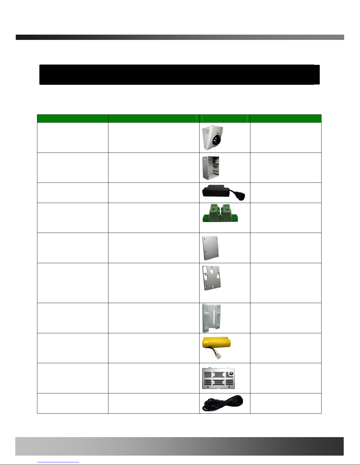
2.1. Contents
Open the package and check if you have the followings:
Contents Description Shape Remarks
Main Body iCanView290PT/290PTW
Network Camera
Adaptor Box Back Box for housing adaptors
Power Adaptor Power adaptor with
proprietary PoE, or PLC.
PLC adaptor is
optional.
AC connector PBA Installed inside the Back box
for connecting AC power to
the power supply.
Adaptor box cover Back box cover.
Mounting bracket Mounting bracket for installing
the main body on the wall or
connecting the power adaptor
box with the main body.
Corner Mount
Bracket
Corner Mount Adapter
Battery Li-ion battery pack
Battery cover Battery compartment cover.
AC cable AC cable
Rev.1.0 (Jun. 2007)
9 of 55

iCanView290PT/290PTW User’s Guide
LAN cable Short Network LAN cable for
Ethernet and PoE applications
Screws and
mounting fixtures
Screws (33 pieces or 7 types)
and washers (15 pieces of 3
types)
Terminal block Terminal block for connecting
one sensor input and one
relay output.
CD & Documents Software & User’s Guide
2.2. Preview
iCanView290PT/290PTW IP-Installer i-NVR
1CH MPEG-4 Network
Camera
PC software to allocate an IP
address to the
iCanView290PT/290PTW
PC software to view and record
the A/V streaming data
transmitted from
iCanView290PT/290PTW
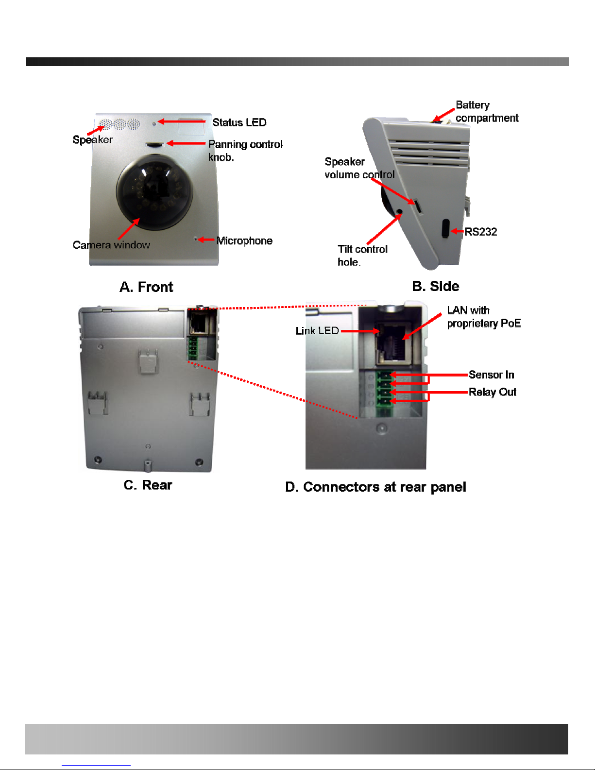
2.3. Physical description
2.3.1. Switches and Knobs for the adjustment
Figure 2-1 Exterior view - - iCanView290.
Rev.1.0 (Jun. 2007)
10 of 55
iCanView290PT/290PTW User’s Guide
Figure 2-1. Front (A), Right(B), Rear(C) views and Connectors(D) of
iCanView290PT/290PTW
y Status LED: Integrated microphone
Status LED: Green color indicates that the camera is in normal operation mode, while RED
color indicates that the camera is in abnormal condition.
y MICROPHONE: Integrated microphone
y Speaker: Integrated speaker
y Pan control knob: (only used for models without Pan/Tilt motor)
Rotate the knob to adjust pan position.
y Tilt control hole: (only used for models without Pan/Tilt motor)
Rev.1.0 (Jun. 2007)
11 of 55

iCanView290PT/290PTW User’s Guide
Adjust the pan control knob so that the camera module is positioned to the desired center of
the pan range, next, insert a (flat head type) “-“screw driver through the hole on the side of
the camera to adjust o the desired tilt angle of the camera.
y Speaker volume control knob: Control knob for adjusting the volume of the speaker.
y LAN with PoE : 100Mbps Ethernet connector (RJ-45) with proprietary PoE.
Both DC power and Ethernet signal are connected through this jack.
- Link LED: Continuous yellow light indicate s that a network cable is plugged in. It will flicker
when there is traffic.
y RS-232C
RS232C interface is provided through mini-USB type connector. The pin assignments are
shown in the following table. RS-232C is reserved for factory usage on ly.
Pin Description Misc.
3 TxD of RS-232C For debugging & factory use only.
4 RxD of RS-232C For debugging & factory use only.
5 Ground of RS-232C For debugging & factory use only.
y Sensor In/Relay Out: used for connecting input sensors, and alarm devices to
iCanView290PT/290PTW.
Pin number Description Misc.
1 Sensor In (+) NC/NO selectable in admin mode.
2 Sensor In (-) NC/NO selectable in admin mode.
3 Relay out Normal close
4 Relay out Common
Sensor Input : Connect external alarm sensors such as the infrared sensors, heat
sensors, magnetic contcats, etc. (NC/NO selectable on the admin page.)
Relay Output : It is used for connecting external alarm generators such as sirens,
flashing light, etc. When activated, relay output configures a closed circuit.
Please refer to Section 6.1 for more detailed description on the Sensor In and Relay
Out connections.
y Reset: Used for returning the network camera to the factory default state. One must open the
Rev.1.0 (Jun. 2007)
12 of 55
iCanView290PT/290PTW User’s Guide
cover in order to access the switch. To reset: Power down the camera, next while powering up
the camera, hold down the reset switch for three seconds.
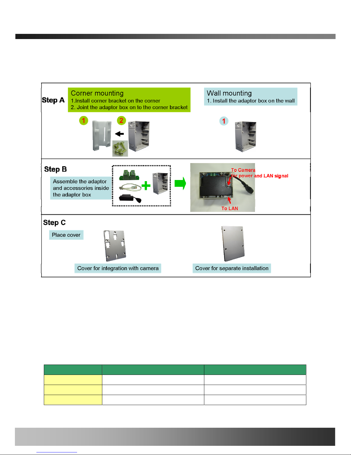
2.3.2. Power Adaptor and Accessories
Figure 2-2. PoE power adaptor, accessories and installation
2.4. PC Requirements
Install the included i-NVR application to your PC for video and synchronized audio recording and
remote monitoring of your iCanView 290(s). Refer to the included separate software manual for
exact software specifications and instructions. Minimum PC requirements:
Minimum Recommended
CPU Pentium III 700 Pentium IV 1.2G above
Main Memory 128 MB 256MB above
Operating system
*
Windows 2000 or later Windows 2000 or later
Rev.1.0 (Jun. 2007)
13 of 55
iCanView290PT/290PTW User’s Guide
Web browser Internet Explorer 5.0 Internet Explorer 5.0 above
Resolution 1,024 X 768 Higher than 1,024 X 768
Network 10 Base-T Ethernet 100 Base-T Ethern et
* Operating Systems supported : Windows XP Professional / Windows XP Home Edition
* Windows 2000 Professional
* Limited Support because Microsoft discontinued
Windows Vista Support Coming Soon!
2.5 Quick Installation Guide
This is a quick reference for experienced installers. For more detailed information please refer to
the installation manual and or the iCanTek home page (
http://www.icantek.com). The
Download Center menu provides updates for Software, Firmware, and Manuals.
Registration is required.
1. Install the battery in the battery compartment and place the battery cover lid.
2. Assemble the power adaptor box as required for your installation condition.
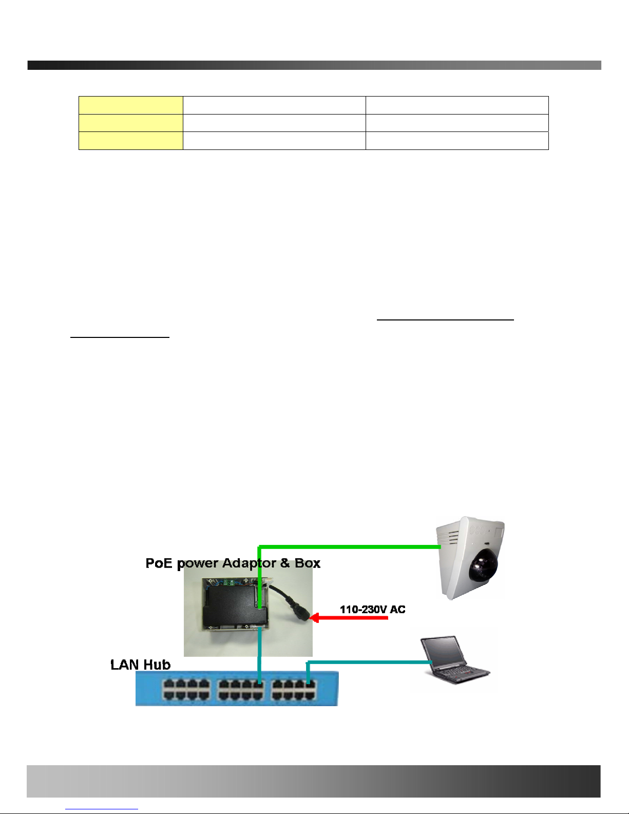
3. Connect iCanView290PT/290PTW to LAN by using one of the following methods
1) If you have PoE power adaptor, connect the network camera and PC as illustrated in
Figure 2.3. Both power and network connection are made with a single LAN cable.
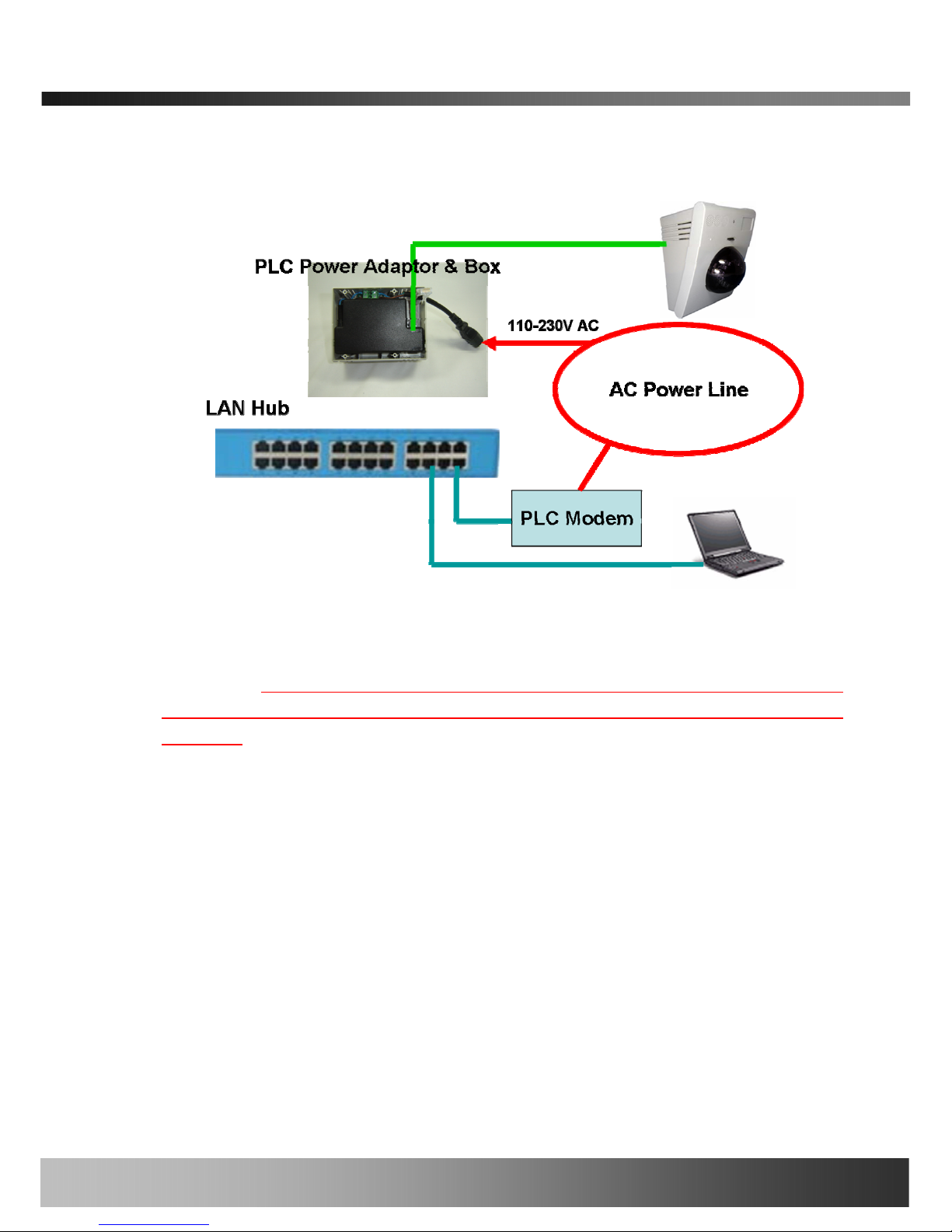
2) If you are using the power adaptor with PLC, connect the network camera and PC as
illustrated in Figure 2.4.
Rev.1.0 (Jun. 2007)
14 of 55
iCanView290PT/290PTW User’s Guide
Figure 2-3. Connecting Network camera and PC using PoE Power Adaptor
Figure 2-4. Connecting Network camera and PC using PLC Adaptor
1. <Caution>:
Note: iCanTek cameras use proprietary PoE technology. Using a third
part PoE product with iCaNtek cameras will damage the camera and void the
warranty.
2. Apply power to iCanView290PT/290PTW
3. Install “IP installer” and “i-NVR” on your PC.
Detailed information for installing these programs can be found in [IP-Installer User’s
Guide] and [i-NVR User’s Guide], respectively.
4. Assign IP address to iCanView290PT/290PTW using IP installer.
Identify the type of the network environment and set up IP address. Detailed process of
setting up IP address can be found in [IP-Installer User’s Guide]. If network type is
xDSL or Cable modem you need supplementary information provided by your ISP.
5. Connect to iCanView290PT/290PTW in Administrator Mode for initial parameter
Rev.1.0 (Jun. 2007)
15 of 55

iCanView290PT/290PTW User’s Guide
set-up.
All parameters are set to factory default state when iCanView290PT/290PTW is delivered.
You are asked to configure the system for your environment in administration mode.
Detailed information of using administration mode can be found in [5. Configuring
iCanView290PT/290PTW in Administrative Mode]. Among the parameters, the
parameters in the following table should be set-up with proper values. Detailed information
for the parameters in Administrator Mode is found in [5. Configuring
iCanView290PT/290PTW in Administrative Mode]
[Note]: Set-up values are preserved even the power is turned off.
Page Parameter Setup value Factory default value
Video Size
Set the resolution of the video
transmitted from
iCanView290PT/290PTW.
Max Upload Rate
Set this value smaller than the upload
speed of your network.
Frame Rate
The number of frames to be
transmitted per second.
Basic Setup
Video Rate
Bandwidth assigned for video
transmitted from
iCanView290PT/290PTW.
Make sure that you press Check
button to find out the number of
maximum possible simultaneous
users then set the number of
users smaller than or equal to the
number.
User Admin
& Time
Setup
Administrator
name &
password
For safety, you are recommended to
change these values from factory
default. For new connection, you need
to input changed values for
corresponding fields. Do not disclose
these values to others and memorize
these values.
Default value
User name : root
Password : dw2001
User Admin
& Time
Setup
Current Time
Input correct time in this field.
Default value :
2001/1/1
6. Connect the input and output signals to iCanView290PT/290PTW.
Connectors Function Signal description Number
Sensor In
Connecting IR sensor, Motion Sensor, Smoke 1
Rev.1.0 (Jun. 2007)
16 of 55

iCanView290PT/290PTW User’s Guide
Alarm Sensor Detector…
/Relay Out
Connecting
Alarm
annunciating
device
Siren, Flashing Light, … 1
LAN
Network & Power
connection
Connect iCanView290PT/290PTW to
the network, LAN, ADSL or Cable
modem and DC power.
1
DC Power
Power is applied through LAN
connector
1
7. Remote video connection to iCanView290PT/290PTW
Run i-NVR on your PC. Before connecting to iCanView290PT/290PTW it is needed to
configure the connection information on the i-NVR. More detailed information of using “i-
NVR” can be found in [i-NVR User’s Guide].
Rev.1.0 (Jun. 2007)
17 of 55
 Loading...