

iCanTek iCanView270 User Manual
iCanView270 User’s Guide
Rev1.0(Aug.2007)

iCanView270 User’s Guide
Use only the AC power adapter which conforms to the specification in data sheet or optionally provided DC
power adapter with the iCanView270.
If you would like to use the iCanView270 for security, monitoring, please check the legal regulations within the
country.
Note
This equipment has been tested and found to comply with the limits for a Class A digital device, pursuant to
part 15 of the FCC Rules. These limits are designed to provide reasonable protection against harmful
interference in a residential installation. This equipment generate, use and can radiate radio frequency energy
and, if not installed and used in accordance with the instructions, may cause harmful interference to radio
communications. However, there is no guarantee that interference will not occur in a particular installation. If
this equipment does cause harmful interference to radio or television reception, which can be determined by
turning the equipment off and on, the user is encouraged to try to correct the interference by one or more of
the following measures
z Reorient or relocate the receiving antenna.
z Increase the separation between the equipment and receiver.
z Connect the equipment into and outlet on a circuit different from that to which the receiver is
connected
z Consult the dealer or an experienced radio/TV technician for help.
Be careful not to cause any physical damage by dropping or throwing the iCanView270 network camera.
Especially keep the network camera out of reach of children.
Do not disassemble iCanView270. Warrantee terms and conditions are not applied for the units that went
through disassembly process.
iCanView270 series network cameras are designed for outdoor/indoor use. Don’t use iCanView270 in an
environment beyond the condition limit.
Directions
Rev.2.0 (Nov.2007)
2
iCanView270 User’s Guide
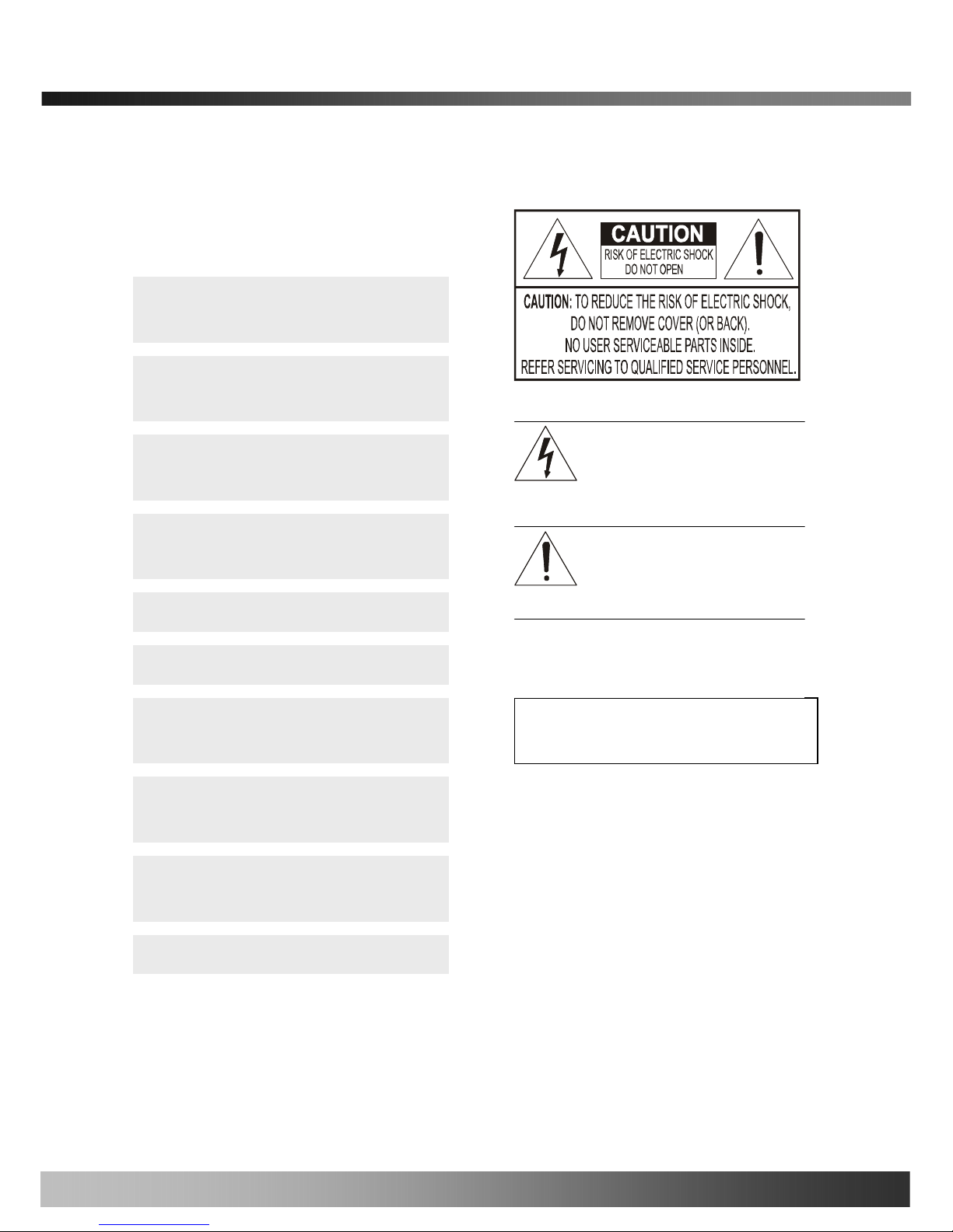
This symbol is intended to alert the user to
the presence of important operating and
maintenance (servicing) instructions in the
literature accompanying the appliance.
This symbol is intended to alert the user to
the presence of un-insulated “dangerous
voltage” within the product’s enclosure that
can cause electric shock..
If you fail to read this information and
handle the product incorrectly, death or
serious injury may occur.
The unit should be installed by trained
personnel.
Always stop using when the product emits
smoke or abnormal heat.
Never install the product in area exposed to
oil or gas.
Never install the product on a ceiling that
cannot hold its weight.
Never expose the product to direct sunlight
or severe ray.
Never touch the front glass of the product.
Never drop, hit strongly nor vibrate the
product.
Never use the product in extremely high or
low temperature condition.
Clean only with dry cloth.
Never touch the power cord with wet hands.
Warning & Caution
Additional Warning & Caution
for iCanView270
Do not apply force to adjust Pan/Tilt
position. It may causes serious damage
Rev.2.0 (Nov.2007)
3

iCanView270 User’s Guide
Revision History
Date Rev. No Description
2007-08-10 1.0 Creation of the document
Rev.2.0 (Nov.2007)
4

iCanView270 User’s Guide
Table of Contents
1. Introduction.........................................................................................................................................................6
1.1. Overview............................................................... .............................................................. 6
1.2. Features of iCanView270..................................................................................................... 6
1.3. Applications of iCanView270............................................................... ................................. 9
2. Product Description...........................................................................................................................................10
2.1. Package Contents............................................................................................................. 10
2.2. Preview............................................................................................................................. 10
2.3. PC Requirements.............................................................................................................. 11
2.4. Physical description........................................................................................................... 11
2.5. Specification of the analog camera module............................................................... ......... 14
2.6. Quick Installation Guide..................................................................................................... 15
3. Connecting iCanView270 to IP Network...........................................................................................................18
3.1. Connecting to LAN ............................................................................................................ 18
3.2. Connecting to xDSL/Cable Modem.................................................................................... 19
4. IP-Installer.........................................................................................................................................................21
4.1. Main window of IP-Installer................................................................................................ 21
5. Configuring iCanView270 in Administrative Mode............................................................................................22
5.1. Log On.............................................................................................................................. 22
5.2. Basic Setup....................................................................................................................... 24
5.3. Network Configuration....................................................................................................... 26
5.4. User Admin & Time Setup.................................................................................................. 29
5.5. Sensor & Capture Setup.................................................................................................... 32
5.6. Alarm Device Setup........................................................................................................... 34
5.7. Motion Region Setup......................................................................................................... 36
5.8. PTZ Setup......................................................................................................................... 38
5.9. Encryption Set up.............................................................................................................. 40
5.10. Upgrade & Reset............................................................................................................. 42
5.11. Status Report ............................................................... .................................................... 44
6. Tips for Using iCanView270..............................................................................................................................45
6.1. Alarm (for Sensor input) and AUX(for Relay output) ........................................................... 45
6.2. Trouble Shooting............................................................................................................... 48
6.3. Web Viewer....................................................................................................................... 50
6.4. How to upgrade iCanView270 firmware ............................................................................. 51
Appendix 1. On Site Installation of iCanView270.................................................................................................53
Rev.2.0 (Nov.2007)
5

iCanView270 User’s Guide
1. Introduction
1.1. Overview
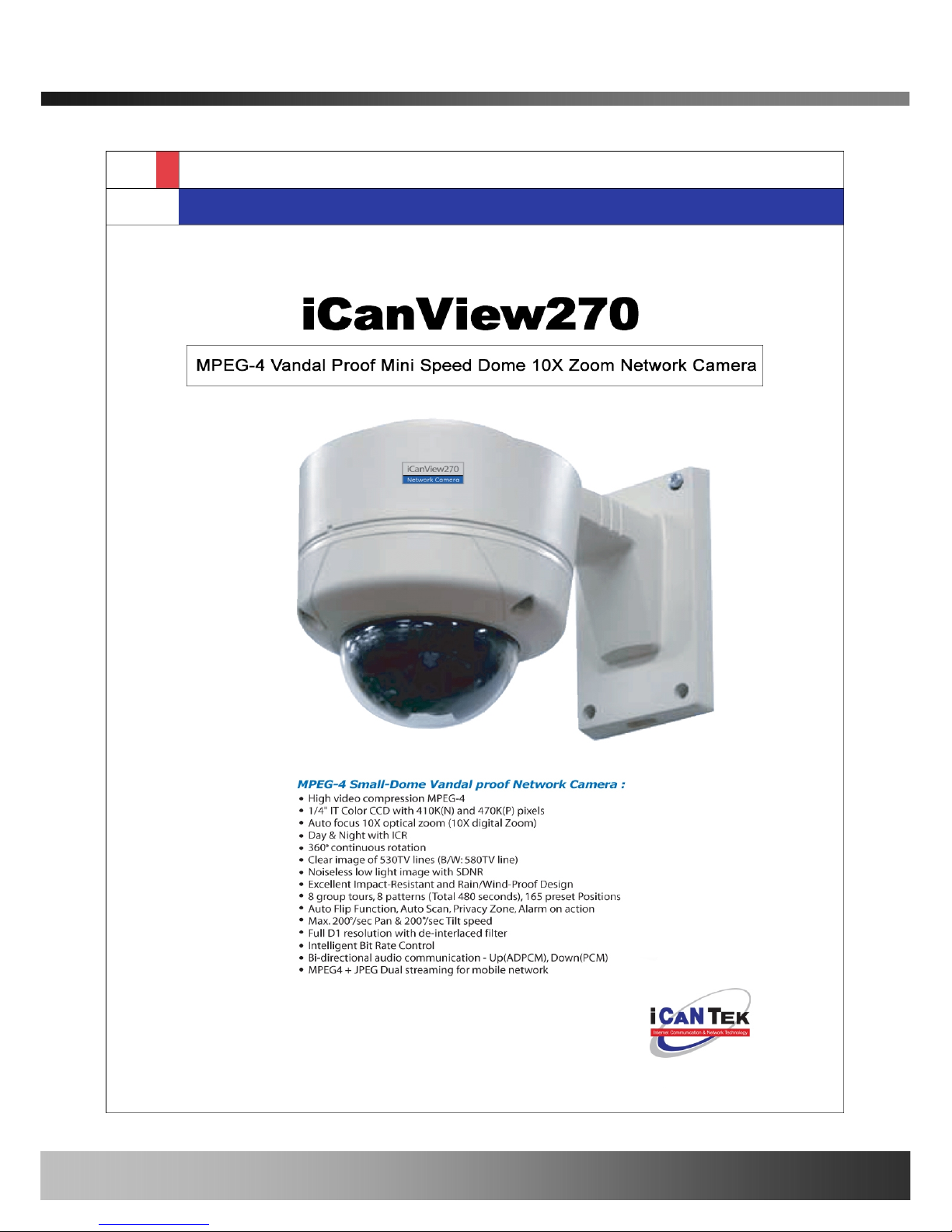
The iCanView270 is a state-of-the-art Speed Dome network camera which transmits synchronized video and
audio data in real time with D1 resolution at full frame rate. This is possible through MPEG4 CODEC technology,
which provides high quality video with highly compressed data streams. The iCanView270 can be connected,
controlled and monitored from a remote location through an IP connection over internet or intranet. Unlike CCTV
or DVR, the iCanView270 is easy to install and owner will experience cost and space savings in the installation
owing to the state of the art technologies embedded in the system. Based on Embedded Software Solution
(Embedded Web Server, Embedded Streaming Server, Network Protocol), the iCanView270 ensures
unprecedented performance and stability to be an ideal network camera solution for system integration solutions.
iCanView270 is offered with standard Ethernet interface.
1.2. Features of iCanView270
y Vandal proof mini speed dome 10X optical zoom & 10X digital zoom.
y 1 channel synchronized real time Video/Audio streaming MPEG-4 video, ADPCM audio.
y Bi-directional audio communication
Real time audio communication between iCanView270 and Client PC
y The viewer assisted recording and playback functions
y Filter Changeable Type Day & Night
y IP66 water-resistant
y 100x Zoom(10x Optical with 10x Digital zoom)
y 350 degree continuous rotation
y Clear image of 530TV line(B/W:580TV line)
y Noiseless low light image with SDNR
y Day&Night with ICR
y Max. 200 degree/sec Pan & Tilt speed
y Max 30 frames/sec(NTSC) and Max 25frames/sec(PAL) @ D1 resolution
y Full D1 Resolution with De-interlaced filter
y Versatile PTZ control
Client viewer assisted PTZ control,
Dedicated virtual system controller for PTZ control on the client
Simultaneous connection & control over IP and RS485
y 2 Alarm sensor inputs / 1 relay outputs
Rev.2.0 (Nov.2007)
6

iCanView270 User’s Guide
y Motion detection – Up to 3 motion detection zones. Arbitrary shape motion detection zone
Motion detection can initiate video recording, which is sent to the user through FTP and/or E-mail.
y Resolution
- NTSC : 720x480, 352x240, 176x144. - PAL/SECAM : 720x576, 352x288, 176x144
y Remote administration control
Entire operational parameter set up, Software upgrade
Rev.2.0 (Nov.2007)
7

iCanView270 User’s Guide
y
Detailed Features of Speed Dome part
General Features of Outdoor Housing (iCan
100X Zoom Mini Speed Dome
10X Optical Zoom with 10X digital zoom
±0.02° dome system accuracy with 1/4
micro step
By adopting 1/4 micro step and twin gear system, the dome
camera achieved 0.1° rotational accuracy. It provides excellent
precision for delicate control such as preset positions.
360° Endless Rotation
Preset position compensation
It minimizes the effect of low frequency vibration caused by
wind or other impact for maintaining precise positioning. It is
useful for outdoor surveillance and traffic monitoring
applications.
Over 200°/Sec Preset Speed
Polarity Protection of Power (DC12V)
This protection function prevents the power board from being
out and trouble when power source falsely connects to the
power terminals.
Protected RS485 terminals. (Against
misconnection of the power line)
RS-485 circuit is protected against false connection of the power
source for ensured communication channel.
Filter changeable True Day/Night (ICR
Block Filter)
Automatic IR cut filter ensures near-true color video for day time
while providing quality B/W video under low illumination. The
efficiency of the monitoring can be improved by using this
feature used together with DSS (Digital Slow Shutter).
Indoor / Outdoor applications
Aluminum case and PC cover (IP66)
Elegantly designed aluminum body and Poly Carbonated dome
cover provide weather proof environment to the internal
modules. (IP66 Rated)
Hot Keys
This camera supports various hot key functions
for ease of control by other controllers or DVRs.
Various Surveillance Functions
Auto Scan continuously repeats movement between two
preset positions with various speed and dwell time.
8 Group Tour : Up to 8 Programmable Group tours are
supported. Each group can be configured to have up to 60
preset positions with different speed and dwell time
165 Preset positions : Up to 165 programmable preset
positions. Each preset position can be labeled by up to 16
characters
8 Patterns :
up to 8 user-defined patterns. Each pattern can
last up to 60 seconds and can be named with up to 16
characters. Total of 480 second of pattern monitoring is
possible.
8 Sectors :
Up to 8 user-defined sectors. Each sector can
be labeled by up to 16 characters
4 Privacy Masking Zones :
Up to 4 user-defined privacy
masking zone. Each zone can be labeled by up to 16
characters
2 Alarm input and 1 relay out
: 2 alarm inputs and 1
relay outputs that can be matched with preset, tours, and
patterns for versatile monitoring functions.
High speed Pan & Tilt movement
Maximum speed for the panning and tilting are 350° /sec and
250° /sec, respectively, for preset movement. The high speed
will enable quick movement to the spot you want to watch..
150°/S – Manual Operation speed
This camera provides up to 150°/sec of manual speed and it’s
adjustable from 100°/sec to 150°/sec
1/4” Sony Super HAD CCD
Sony Super HAD CCD for excellent sensitivity and low smear
levels.
Multiple language support
Intelligent Pan/Tilt Controlling
Pan and tilt speed is adjusted in connection with zoom factor.
Rev.2.0 (Nov.2007)
8

iCanView270 User’s Guide
1.3. Applications of iCanVi ew270
y IP surveillance (buildings, stores, manufacturing facilities, parking lots, banks, government facilities, military, etc.,
y Real time Internet broadcasting
y Remote monitoring (hospitals, kindergartens, traffic, public a reas, etc.,)
y Teleconference (Bi-directional audio conference)
y Remote Learning
y Weather and environmental observation
Rev.2.0 (Nov.2007)
9
iCanView270 User’s Guide
2. Product Description
2.1. Package Contents
Open the package and check if you have the followings:
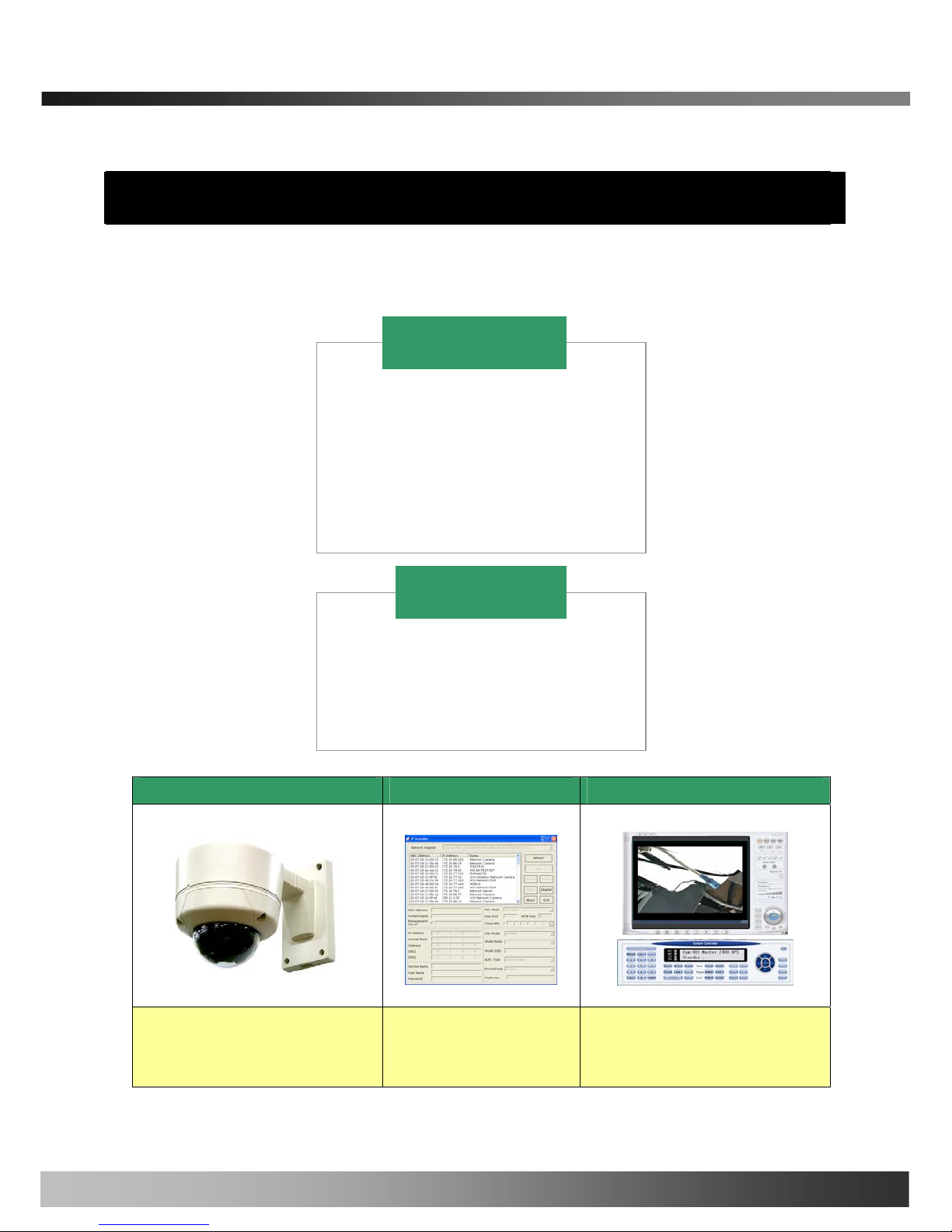
2.2. Preview
iCanView270 IP-Installer i-NVR & Virtual System Controller
MPEG-4 Speed Dome Network Camera
PC software to allocate IP
parameters to iCanView270
PC software to view and record the A/V
streaming data transmitted from
iCanView270
3. PLC adaptor
1. Wall Mount Bracket
2. PoE injector or Adaptor
1. Camera main body
2. CD(Manual, S/W)
3. Screw (Ø 4x16 screw 5EA,
Ø4x16 screw 5EA )
4. Manual
5. Terminal Block (5Pin 2EA)
iCanView270
Optional Items
Rev.2.0 (Nov.2007)
10
iCanView270 User’s Guide
2.3. PC Requirements
AV streaming data received from iCanView270 can be decoded or stored in a PC running i-NVR program which is
a viewing & recording program for a PC. Minimum requirement of the PC is described below:
Recommended
CPU
Pentium IV 1.8G above
Main Memory
512MB above
Operating system
*
Windows 2000 or later
Web browser
Internet Explorer 6.0 above
Resolution
1280 X 1024
Network
100 Base-T Ethernet
* Operating Systems supported : Windows 2000 Professional
Windows XP Professional / Windows XP Home Edition
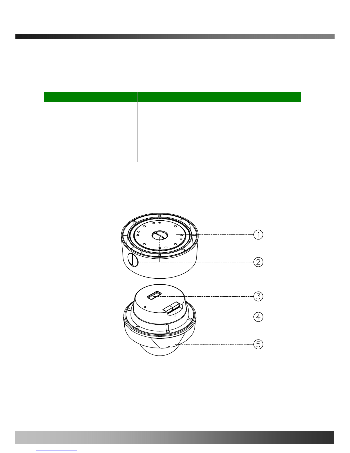
2.4. Physical description
2.4.1 Bottom View and Name
1. Surface Mount Adaptor
2. Cap Screw ( PT3/4 , 2EA )
3. Dip Switch
4. Terminal Block
5. Main body
Rev.2.0 (Nov.2007)
11
iCanView270 User’s Guide
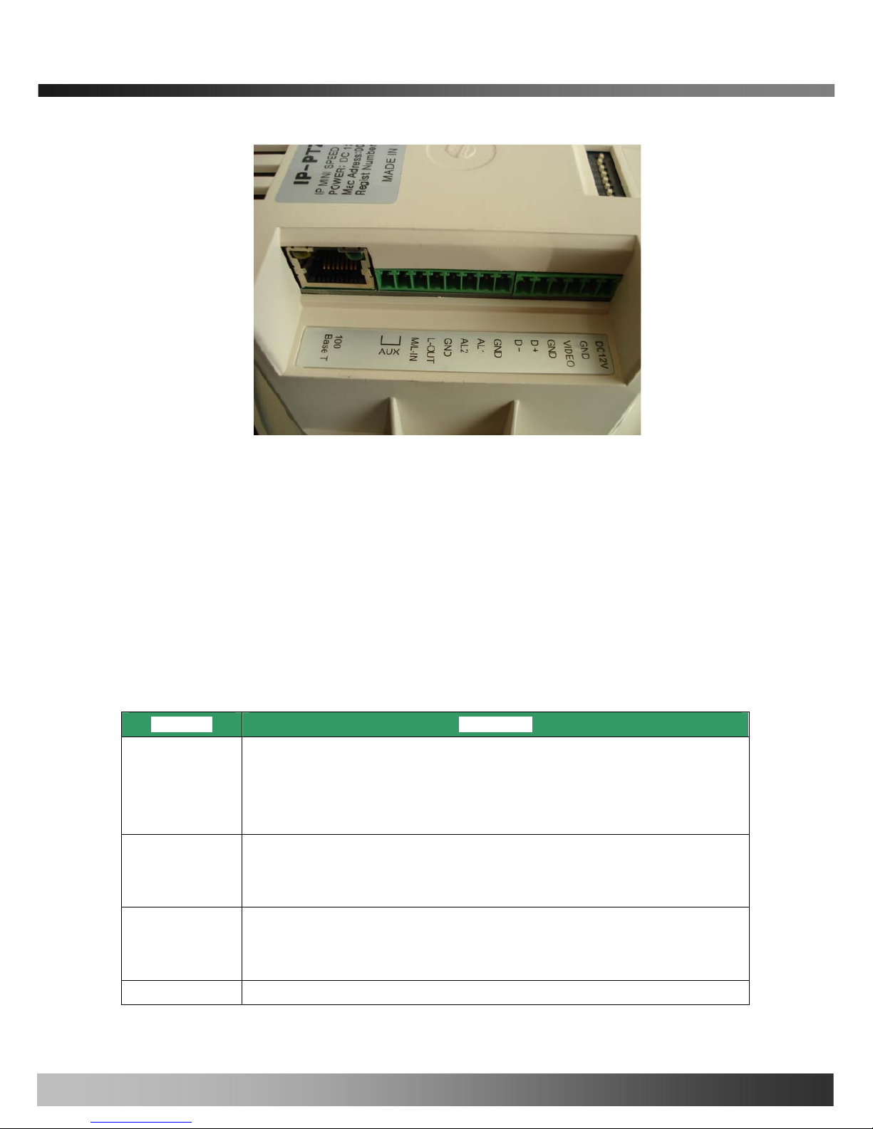
-Connector
100 Base T : RJ-45 connector for conne cting LAN (100 Base-T)
The power can also be applied through the RJ-45 connector using proprietary PoE injector or PoE
adaptor supplied by iCanTek.
When the power is applied through the RJ-45 connect, do not apply power using DC12V pins.
-T erminal Block
Refer to the following table for pin configuration.
Pin Name Description
AUX
. 1 Relay output
. Use the two pins to connect the alarm annunciating device such as sirens,
flashing light, etc., to network camera.
Please refer to the section 6.1 for more detailed description.
M/L-IN
. Connect external Microphone or audio to network camera.
Input audio/voice is compressed in network camera for synchronized
transmission with video to client PC through IP network
L-OUT
. Connect a speaker with amplifier. LINE OUT
. Audio/voice from client at remote site can be output through the line out terminal
in bi-directional audio mode of iNVR or NVR-Pro.
AL1, AL2
. 2 Alarm inputs
Fig.2-1 detailed view of iCanView270
Rev.2.0 (Nov.2007)
12
iCanView270 User’s Guide
. Connect external alarm sensors such as the infrared, heat, magnetic sensor to
network camera.
Connect one end of the alarm device to GND.
. Sensor type(Normal Open or Normal Close) can be selected using Virtual System
Controller (Keyboard Emulator) in i-NVR (for detailed information, please refer to
the i-NVR user’s guide in CD)
D+, D-
. Connect external RS485 device such as System Controller (Keyboard) or DVR to
iCanView270 network camera
VIDEO
. Composite video output from the camera.,
DC12V
. Connect 12 Volt DC adaptor to this terminal for supplying power to the network
camera.
. Power adapter which is compliant to the specification for iCanView270
should be used. Misuse of power supply can cause damage to
iCanView270.
ICANTEK assumes no responsibility for misuse of the power supply.
The power can also be applied through the RJ-45 connector using
proprietary PoE injector or PoE adaptor supplied by iCanTek.
When the power is applied through the RJ-45 connect, do not apply power
using DC12V pins.
GND
Ground
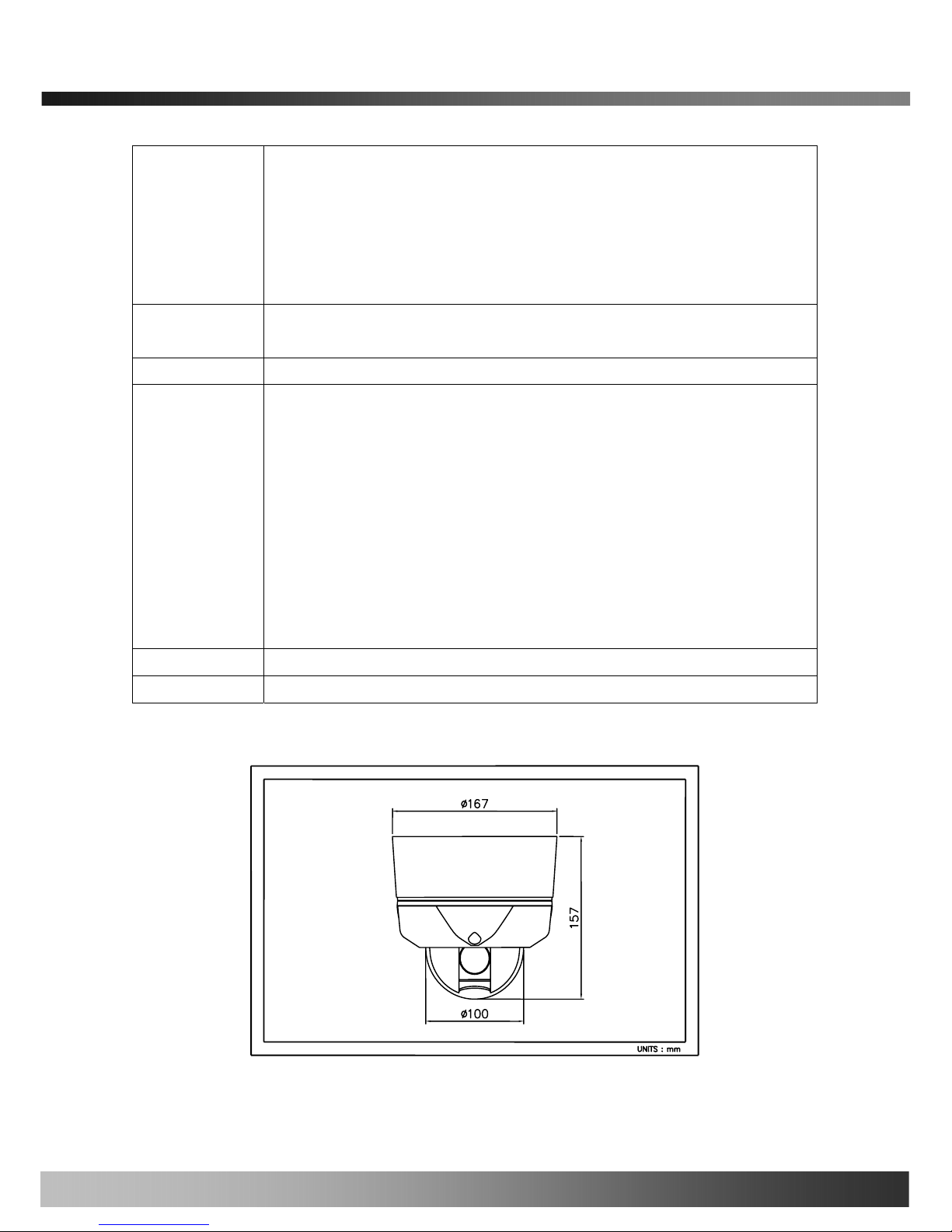
2.4.2 Dimension and basic parts of CanView270
Fig 2.2 Dimension of iCanView270 (unit : mm)
Rev.2.0 (Nov.2007)
13

iCanView270 User’s Guide
2.5. Specification of the analog camera module
2.5.1. Zoom camera
Camera module Lens Misc.
10X Zoom Zoom Camera PAL or NTSC
2.5.2 Detailed specifications of the analog camera
10X A/F CAMERA MODULE
Pan Rotation Angle
360˚ Endless
Manual
100˚ ~ 150˚/sec
Pan Speed
Preset
Max 200˚ /sec
Tilt Rotation Angle
0˚ ~ 90˚
Manual
100˚ ~ 150˚/sec
Tilt Speed
Preset
Max 200˚ /sec
Pan/Tilt
Rotational Resolution
0.02˚
Preset
165 positions identifiable with 16 character label.
Different speed steps
Group Tour
Max. 8 Programmable group tours
(each one consisting of up to 60 preset steps with different steps)
Auto scan
Programmable Auto scan
Pattern
8 Programmable Patterns (total 480 seconds)
Privacy Zone
4 privacy zones
Sector
8 Sectors identifiable with 16 character label.
Password Protection
Yes
Alarm Input
2 alarms (OFF/NC/NO selectable)
Alarm Actions
Activate preset, Group scanning or output on alarm input
Aux Output
1 Replay Outputs
Auto Flip
ON / OFF
OSD Menu
Multiple Languages support
Communication
RS-485
Functions
Image Sensor
1/4"Sony super HAD CCD
NTSC
811(H) * 508(V) 410K
Number of
Pixels
PAL
795(H) * 596(V) 470K
NTSC
768(H) * 494(V) 380K
Camera
Module
Number Of
Effective
Pixels
PAL
752(H) * 582(V) 440K
Rev.2.0 (Nov.2007)
14

iCanView270 User’s Guide
Horizontal resolution
More Than 500TV Lines
Optical
10x Optical Zoom
(F=3.8 to 38mm)
Zoom
Digital
10x (100x with optical)
Day & Night (ICR)
Auto/ Day/ Night
Minimum Shooting
Distance
0.35m(Wide)/0.8m(Tele)
Digital Slow Shutter
2/4/8/16/24/32/64/128/ OFF
Normal
mode
0.7Lux (50IRE)
Min.
illumination
Night
mode
0.02Lux (ICR On)
Luminance S/N Ratio
More than 50dB
Video Output
VBS:1.0Vp-p / 75Ohm
BLC
ON / OFF
NTSC
ON / OFF (1/100)
Flickerless
PAL
ON / OFF (1/120)
White balance
AWB/ATW/INDOOR/ OUTDOOR
2.6. Quick Installation Guide
Brief information for rapid installation is provided in this section. For more detailed information you are
recommended to refer to pertinent documentations provided with the product or refer to iCanTek’s home page
(
http://www.icantek.com)
1. Apply power to iCanView270 and Connect iCanView270 to LAN like the following picture.
Rev.2.0 (Nov.2007)
15
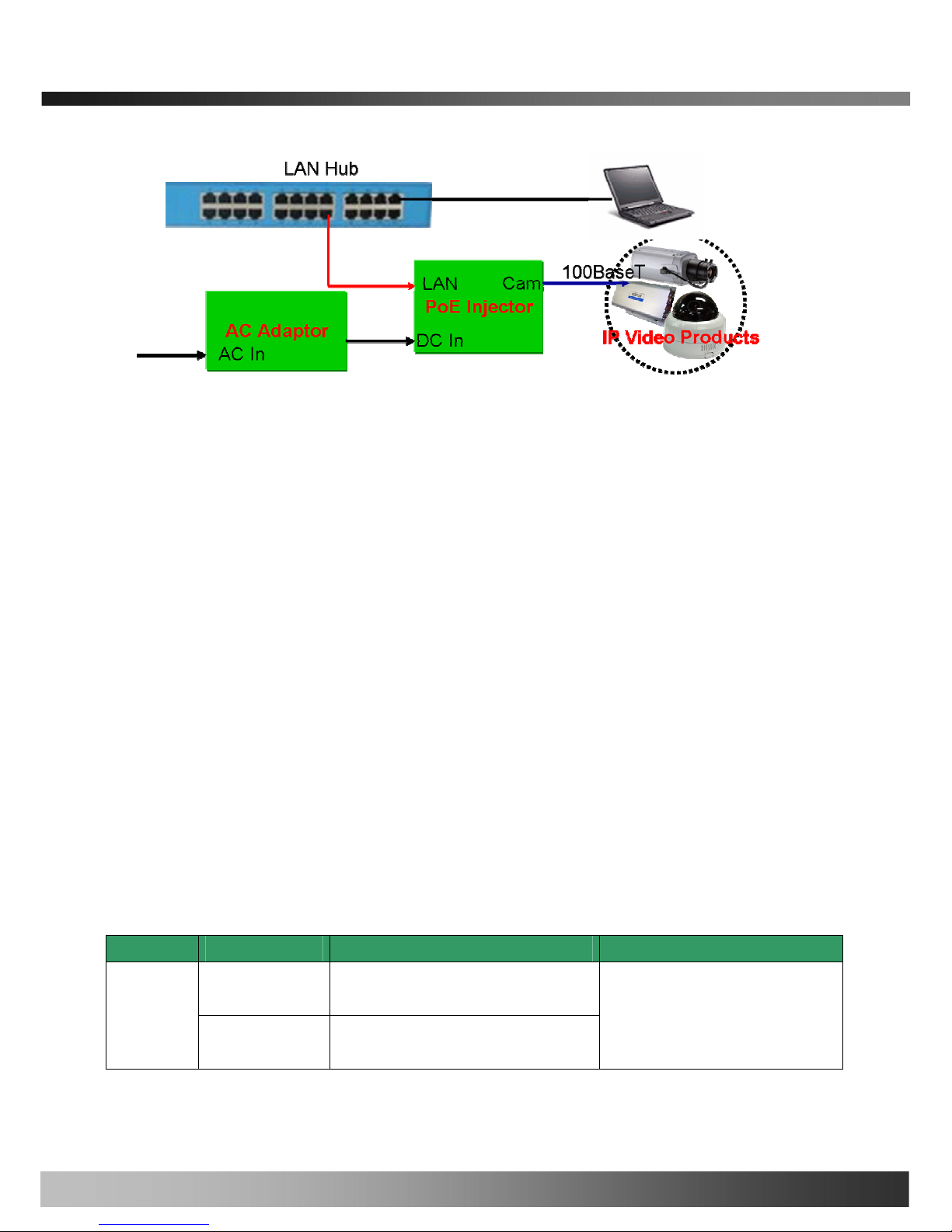
iCanView270 User’s Guide
Fig. 2-5 Connecting Network camera and PC
2. Install “IP installer” and “i-NVR” on your PC.
Detailed information for installing these programs can be found in [IP-Installer User’s Guide] and [i-NVR
User’s Guide], respectively.
3. Assign IP address to iCanV iew270 using IP installer.
Identify the type of the network environment and set up IP address. Detailed process of setting up IP
address can be found in [IP-Installer User’s Guide]. If network type is xDSL or Cable modem you need
supplementary information provided by your ISP.
4. Connect to iCanView270 in Administrator Mode for initial parameter set-up.
All parameters are set to factory default state when iCanView270 is delivered. You are asked to
configure the system for your environment in administration mode. Detailed information of using
administration mode can be found in [5. Configuring iCanView270 in Administrative Mode]. Among
the parameters, the parameters in the following table should be set-up with proper values. Detailed
information for the parameters in Administrator Mode is found in [5. Configuring iCanView270 in
Administrative Mode]
[Note]: Set-up values are preserved even the power is turned off.
Page Parameter Setup value Factory default value
Video Size
Set the resolution of the video transmitted
from iCanView270.
Basic
Setup
Max Upload Rate
Set this value smaller than the upload
speed of your network.
Make sure that you press Check button
to find out the number of maximum
possible simultaneous users then set
the number of users smaller than or
Rev.2.0 (Nov.2007)
16

iCanView270 User’s Guide
Frame Rate
The number of frames to be transmitted per
second.
Video Rate
Bandwidth assigned for video transmitted
from iCanView270.
equal to the number.
User
Admin &
Time
Setup
Administrator name
& password
For safety, you are recommended to
change these values from factory default.
For new connection, you need to input
changed values for corresponding fields.
Do not disclose these values to others and
memorize these values.
Default value
User name : root
Password : dw2001
User
Admin &
Time
Setup
Current Time
Input correct time in this field.
Default value :
2001/1/1
5. Connect the input and output signals to iCanView270.
Connectors Function Signal description Number
Mic/LINE-In
Audio/Voice in
Connect microphone or output from audio
devices.
1
Line Out
Audio out for
speaker
Audio from remote site is available from this
connector in bi-directional audio mode.
Connect speaker with amplifier.
1
Connecting Alarm
Sensor
IR sensor, Motion Sensor, Smoke
Detector…
1
Alarm
/Aux
Connecting Alarm
annunciating
device
Siren, Flashing Light, … 1
Network
Network connection
Connect iCanView270 to the network, LAN,
ADSL or Cable modem.
1
DC12V
Supply DC power Apply DC12V power to network camera 1
6. Remote video connection to iCanView270
Run i-NVR on your PC. Before connecting to iCanView270 it is needed to configure the connection
information on the i-NVR. More detailed information of using “i-NVR ” can be found in [i-NVR User’s
Guide].
Rev.2.0 (Nov.2007)
17
 Loading...