

iCanTek iCanView 240, iCanView 250 User Manual
iCanView240/250 User’s Guide
Rev1.0(Dec.2006)

iCanView240/250 User’s Guide
Use only the AC power adapter which conforms to the specification in data sheet or optionally provided AC
power adapter with the iCanView240/250.
If you would like to use the iCanView240/250 for security, monitoring, please check the legal regulations within the
country.
Note
This equipment has been tested and found to comply with the limits for a Class A digital device, pursuant to
part 15 of the FCC Rules. These limits are designed to provide reasonable protection against harmful
interference in a residential installation. This equipment generate, use and can radiate radio frequency energy
and, if not installed and used in accordance with the instructions, may cause harmful interference to radio
communications. However, there is no guarantee that interference will not occur in a particular installation. If
this equipment does cause harmful interference to radio or television reception, which can be determined by
turning the equipment off and on, the user is encouraged to try to correct the interference by one or more of
the following measures
z Reorient or relocate the receiving antenna.
z Increase the separation between the equipment and receiver.
z Connect the equipment into and outlet on a circuit different from that to which the receiver is
connected
z Consult the dealer or an experienced radio/TV technician for help.
Be careful not to cause any physical damage by dropping or throwing the iCanView240/250 network camera.
Especially keep the network camera out of reach from children.
Do not disassemble iCanView240/250 or After Service Follow-up is not possible.
iCanView240/250 series network cameras are designed for outdoor/indoor use. Don’t use iCanView240/250 in an
environment that exceeds the limited range.
Directions
2

iCanView240/250 User’s Guide
3
If you fail to read this information
and handle the product incorrectly,
death or serious injury may occur .
Never install the product in area exposed to
water, oil or gas.
Never install the product on a ceiling that
cannot hold its weight.
Input power: With Camera - 24V AC
18 watts at 24V AC
Heater: 18watts
Fan: 2watts
The heater activates at +10℃ (±5℃),
deactivates at +15℃(±5℃)
The fan activates at +45℃ (±5℃),
Deactivates at +35℃ (±5℃)
Additional Warning & Caution
for iCanView240
This symbol is intended to alert the user to
the presence of important operating and
maintenance (servicing) instructions in the
literature accompanying the appliance.
This symbol is intended to alert the user to
the presence of un-insulated “dangerous
voltage” within the product’s enclosure that
can cause electric shock..
Never install the product in areas exposed to
rain or water
Never expose the product to direct sunlight
or severe ray.
Never touch the front glass of the product.
Never drop, hit strongly nor vibrate the
product.
Never install the product in extremely high or
low temperature.
Clean only with dry cloth.
Never touch the power cord with wet hands.
If you fail to read this information and
handle the product incorrectly, death or
serious injury may occur.
The unit should be installed by trained
personnel.
Always stop using when the product emits
smoke or abnormal heat.
Never install the product in area exposed to
water, oil or gas.
Never install the product on a ceiling that
cannot hold its weight.
Warning & Caution

iCanView240/250 User’s Guide
Revision History
Date Rev. No Description
2006-12-06 1.0 Creation of the document
4

iCanView240/250 User’s Guide
Table of Contents
1. Introduction ......................................................................................................................................................... 7
1.1. Overview ............................................................... .............................................................. 7
1.2. Features of iCanView240/250.............................................................................................. 7
1.3. Applications of iCanView240/250 ....................................................................................... 10
2. Product Description........................................................................................................................................... 11
2.1. Package Contents ............................................................................................................. 11
2.2. Preview ............................................................................................................................. 11
2.3. PC Requirements .............................................................................................................. 12
2.4. Physical description........................................................................................................... 12
2.5. Specification of the analog camera module and PTZ part ................................................... 16
2.6. Quick Installation Guide..................................................................................................... 18
3. Connecting iCanView240/250 to IP Network.................................................................................................... 21
3.1. Connecting to LAN ............................................................................................................ 21
3.2. Connecting to xDSL/Cable Modem .................................................................................... 22
4. IP-Installer......................................................................................................................................................... 24
4.1. Main window of IP-Installer ................................................................................................ 24
5. Configuring iCanView240/250 in Administrative Mode..................................................................................... 25
5.1. Log On .............................................................................................................................. 25
5.2. Basic Setup....................................................................................................................... 27
5.3. Network Configuration ....................................................................................................... 29
5.4. Wireless Configuration (This is not applicable to iCanView240/250 network camera).......... 32
5.5. User Admin & Time Setup............................................................... ................................... 34
5.6. Sensor & Capture Setup.................................................................................................... 37
5.7. Alarm Device Setup........................................................................................................... 39
5.8. Motion Region Setup ......................................................................................................... 41
5.9. PTZ Setup......................................................................................................................... 43
5.10. Encryption Set up ............................................................................................................ 45
5.11. Upgrade & Reset ............................................................... .............................................. 47
5.12. Status Report .................................................................................................................. 49
6. Tips for Using iCanView240/250....................................................................................................................... 50
6.1. Alarm (for Sensor input) and AUX(for Relay output) ........................................................... 50
6.2. Trouble Shooting ............................................................................................................... 53
6.3. Web Viewer....................................................................................................................... 55
6.4. How to upgrade iCanView240/250 firmware....................................................................... 56
5

iCanView240/250 User’s Guide
Appendix 1. On Site Installation of iCanView250 ................................................................................................. 58
Appendix 2. On Site Installation of iCanView240 ................................................................................................. 63
6

iCanView240/250 User’s Guide
1. Introduction
1.1. Overview
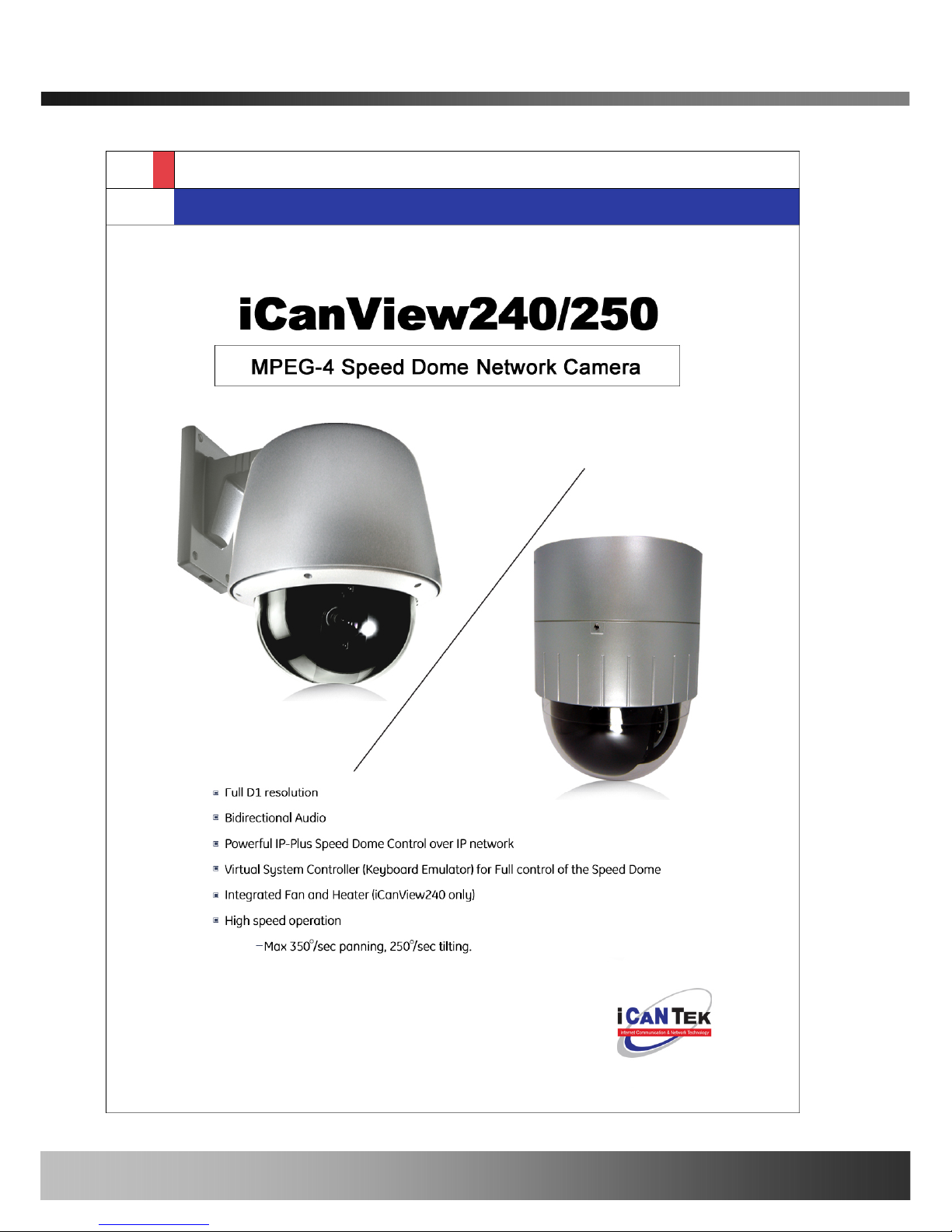
The iCanView240/250 is a state-of-the-art Speed Dome network camera which transmits synchronized video and
audio data in real time with D1 resolution at full frame rate. This is possible through MPEG4 CODEC technology,
which provides high quality video with highly compressed data streams. The iCanView240/250 can be connected,
controlled and monitored from a remote location through an IP connection over internet or intranet. Unlike CCTV
or DVR, the iCanView240/250 is easy to install and owner will experience cost and space savings in the
installation owing to the state of the art technologies embedded in the system. Based on Embedded Software
Solution (Embedded Web Server, Embedded Streaming Server, Network Protocol), the iCanView240/250 ensures
unprecedented performance and stability to be an ideal network camera solution for system integration solutions.
iCanView240/250 is offered with standard Ethernet interface.
1.2. Features of iCanView240/250
y World Most Silent Speed Dome IP Camera
y 1 channel synchronized real time Video/Audio streaming MPEG-4 video, ADPCM audio.
y Bi-directional audio communication
Real time audio communication between iCanView240/250 and Client PC
y The viewer assisted recording and playback functions
y World Most Silent Speed Dome IP Camera (O utdoor Type)
y 1/4 “Sony Ex-view CCD 26x,18x / Super HAD CCD 22x
y Filter Changeable Type Day & Night
y IP66 water-resistant (iCanView240 only)
y 220x Zoom(22x Optical with 10x Digital zoom) Selectable
- 26x/18x (with 12 x digital zoom) Sony zoom camera is optional
y Max 30 frames/sec(NTSC) and Max 25frames/sec(PAL) @ D1 resolution
y Full D1 Resolution with De-interlaced filter
y Versatile PTZ control
Client viewer assisted PTZ control,
Dedicated virtual system controller for PTZ control on the client
Simultaneous connection & control over IP and RS485
y 4 Alarm sensor inputs / 2 relay outputs
y Motion detection – Up to 3 motion detection zones. Arbitrary shape motion detection zone
Motion detection can initiate video recording, which is sent to the user through FTP and/or E-mail.
7

iCanView240/250 User’s Guide
y Resolution
- NTSC : 704x480, 352x240, 176x144. - PAL/SECAM : 704x576, 352x288, 176x144
y Remote administration control
Entire operational parameter set up, Software upgrade
y Various Mounting Brackets
Wall, Pipe, Gooseneck mounting brackets
Corner mount adaptor , Pole mount adaptor
y Built-in Fan / Heater(iCanView240 only)
8

iCanView240/250 User’s Guide
y
Detailed Features of Speed Dome part
General Features of Outdoor Housing (iCan
World most silent speed dome camera
Adoption of timing belt, specialized gear, and other lownoise-technologies reduced mechanical vibration which
significantly enhances durability and quality of the
camera. This camera is the perfect match, both indoor
and outdoor, for demanding security and monitoring
applications.
0.024° dome system accuracy with 1/8
micro step
By adopting 1/8 micro step and twin gear system, the dome
camera achieved 0.024° rotational accuracy. It provides
excellent precision for delicate control such as preset positions.
Reliable RAM-Material
The mechanical stability achieved by using high quality
materials (e.g., stepping motor, slip ring, timing belt
and power condenser) improves the durability and life
time of the camera. The camera housing is made of fire
resistant material (UL grade 94 V-0).
Preset position compensation
It minimizes the effect of low frequency vibration caused by
wind or other impact for maintaining precise positioning. It is
useful for outdoor surveillance and traffic monitoring
applications.
Long life-time Slip Ring ( Passed 6 month
test of 20milion rotations)
Equipped with slip ring that passed 20 millions rotations
performed for 6 months.
Protected RS485 terminals. (Against
misconnection of the power line)
RS-485 circuit is protected against false connection of the power
source for ensured communication channel.
Filter changeable True Day/Night
Automatic IR cut filter ensures near-true color video for
day time while providing quality B/W video under low
illumination. The efficiency of the monitoring can be
improved by using this feature used together with DSS
(Digital Slow Shutter). This f eature is available only for
18X and 26X zoom module.
Hot Keys
This camera supports various hot key functions
for ease of control by other controllers or DVRs.
Various Surveillance Functions
Auto Scan continuously repeats movement between two
preset positions with various speed and dwell time.
8 Group Tour : Up to 8 Programmable Group tours are
supported. Each group can be configured to have up to 60
preset positions with different speed and dwell time
165 Preset positions : Up to 165 programmable preset
positions. Each preset position can be labeled by up to 16
characters
8 Patterns :
up to 8 user-defined patterns. Each pattern can
last up to 60 seconds and can be named with up to 16
characters. Total of 480 second of pattern monitoring is
possible.
8 Sectors :
Up to 8 user-defined sectors. Each sector can
be labeled by up to 16 characters
24 Privacy Masking Zones :
Up to 24 user-defined
privacy masking zone. Each zone can be labeled by up to 16
characters (18X, 26X only)
4 Alarm input and 2 relay out
: 4 alarm inputs and 2
relay outputs that can be matched with preset, tours, and
patterns for versatile monitoring functions.
High speed Pan & Tilt movement
Maximum speed for the panning and tilting are 350° /sec and
250° /sec, respectively, for preset movement. The high speed
will enable quick movement to the spot you want to watch..
200°/S – Manual Operation speed
This camera provides up to 200°/sec of manual speed and it’s
adjustable from 100°/sec to 200°/sec
1/4” Sony Ex-View CCD
Sony Ex-view HAD CCD for excellent sensitivity and low
smear levels (18X 26X only)
Multiple language support
Intelligent Pan/Tilt Controlling
Pan and tilt speed is adjusted in connection with zoom factor.
9

iCanView240/250 User’s Guide
1.3. Applications of iCanVi ew240/250
y IP surveillance (buildings, stores, manufacturing facilities, parking lots, banks, government facilities, military, etc.,
y Real time Internet broadcasting
y Remote monitoring (hospitals, kindergartens, traffic, public areas, etc.,)
y Teleconference (Bi-directional audio conference)
y Remote Learning
y Weather and environmental observation
10
iCanView240/250 User’s Guide
2. Product Description
2.1. Package Contents
Open the package and check if you have the followings:
AC Adapter is Optionally provided
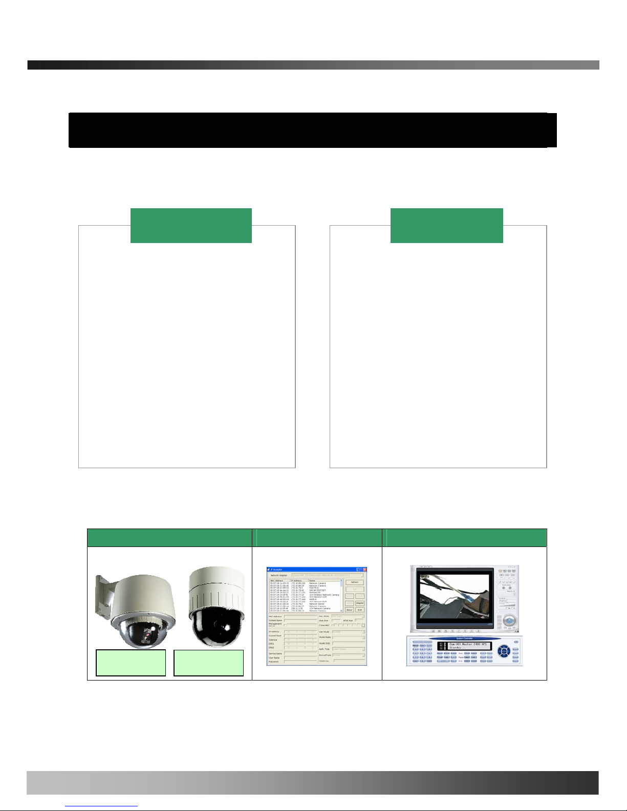
2.2. Preview
iCanView240/250 IP-Installer i-NVR & Virtual System Controller
1. All items of indoor speed dome
network camera
2. Manual for outdoor housing
3. Outdoor Housing
4. Wall Mount Bracket
5. Screw (M4x15 screw 4EA)
6. Safety Cable
iCanView240 = iCanView250 +
Outdoor Housing +
Wall Mount Housing
1. Camera main body
2. CD(Manual, S/W)
3. Ceiling Mount Bracket
4. Wrench
5. Screw (Ø 3x6 screw 2EA,
Ø4x16 screw 5EA )
6. Safety Wire
7. Ceiling Cover
8. Cable ties
9. Terminal Block
(1 EA of 2Pin, 3Pin , 5Pin ,6Pin)
iCanView250
iCanView240
iCanView250
iCanView240
11

iCanView240/250 User’s Guide
PC software to allocate IP
parameters to
iCanView240/250
PC software to view and record the A/V
streaming data transmitted from
iCanView240/250
MPEG-4 Speed Dome Network Camera
2.3. PC Requirements
AV streaming data received from iCanView240/250 can be decoded or stored in a PC running i-NVR program
which is a viewing & recording program for a PC. Minimum requirement of the PC is described below:
Recommended
Pentium IV 1.8G above
CPU
512MB above
Main Memory
Operating system
*
Windows 2000 or later
Internet Explorer 6.0 above
Web browser
1280 X 1024
Resolution
100 Base-T Ethernet
Network
* Operating Systems supported : Windows 2000 Professional
Windows XP Professional / Windows XP Home Edition
2.4. Physical description
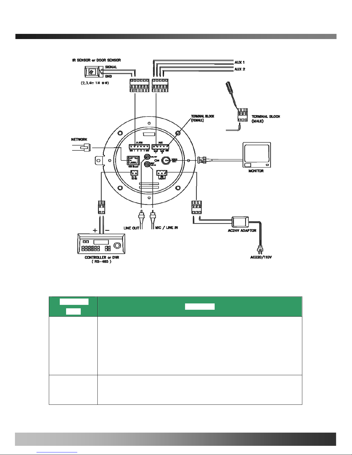
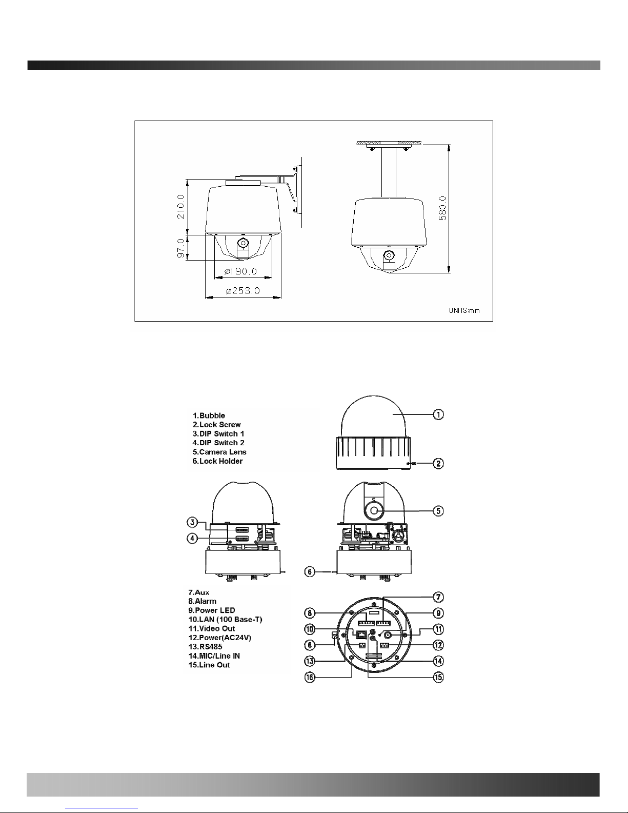
2.4.1 Bottom View and Connections
12
iCanView240/250 User’s Guide
Fig. 2-1 Bottom View of iCanView240/250
- Input/Output Connectors at Bottom panel of iCanView240/250
Connector
Name
Description
. 4 Alarm inputs(Signal pin number : 1, 2, 3, 4), 2 GND(ground) signals
. Connect external alarm sensors such as the infrared, heat, magnetic sensor to
network camera.
. Sensor type(Normal Open or Normal Close) can be selected using Virtual System
Controller (Keyboard Emulator) in i-NVR (for detailed information, please refer to
the i-NVR user’s guide in CD)
ALARM
AUX
. 2 Relay outputs and 1 ground (GND) signal
. Connect external alarm generators such as sirens, flashing light, etc., to network
camera.
13
iCanView240/250 User’s Guide
Please refer to the section 6.1 for more detailed description.
. RJ45 connector, 100Base-T.
. Connects iCanView240/250 to IP network
NETWORK
. Connect external device such as System Controller (Keyboard) or DVR to
iCanView240/250 network camera
RS485
VIDEO OUT
. Composite video output from the camera.,
. Connect a speaker with amplifier.
. Audio/voice from client at remote site can be output through the line out terminal
in bi-directional audio mode of iNVR or NVR-Pro.
LINE OUT
. Connect external Microphone or audio to network camera.
Input audio/voice is compressed in network camera for synchronized
transmission with video to client PC through IP network
MIC/LINE IN
. Connect 24 Volt AC adaptor to this terminal for supplying power to the network
camera.
. AC adapter which is compliant to the specification for iCanView240/250
should be used. Misuse of power supply can cause damage to
iCanView240/250.
ICANTEK assumes no responsibility for misuse of the power supply.
AC24V
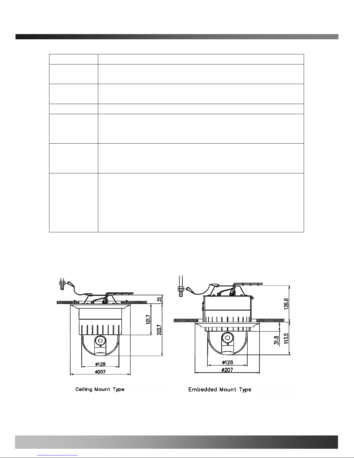
2.4.2 Dimension and basic parts of CanView240/250
A. Dimension
A-1. iCanView250
Fig 2.2 Dimension of iCanView250 (unit : mm)
14
iCanView240/250 User’s Guide
A-2. iCanView240 (iCanView250 + Outdoor Housing)
Fig.2-3 Dimension of iCanView240
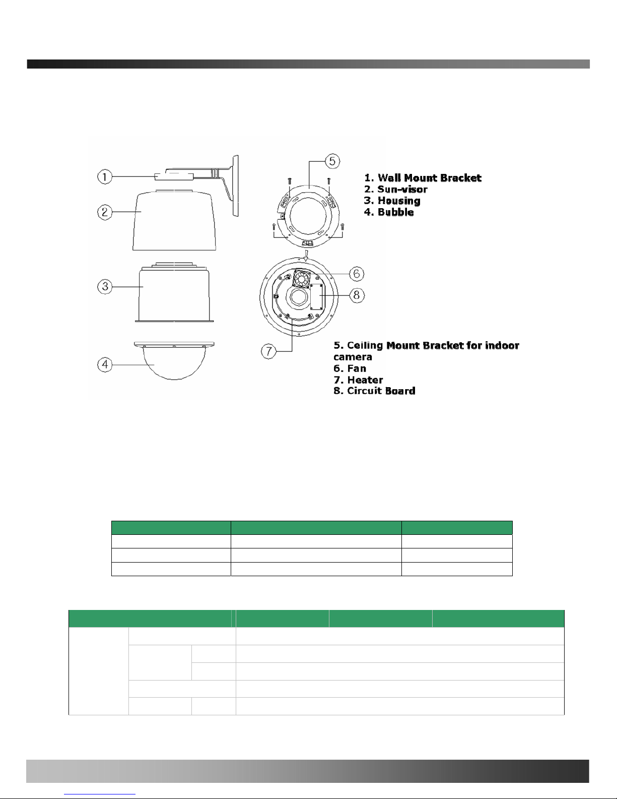
B. Exterior and Interior of View
B-1.Common part of iCanView240/250
Fig.2-5 Common part of iCanView240/250
15
iCanView240/250 User’s Guide
B-2.Outdoor Housing
Fig.2-6. Outdoor housing
2.5. Specification of the analog camera module and PTZ part
2.5.1. Zoom cameras
iCanView240/250 is offered with 3 types of zoom camera modules as described in the following table.
Lens Misc. Camera module
22X Zoom Zoom Camera With DSS PAL or NTSC
18X Zoom Sony Zoom Camera PAL or NTSC
26X Zoom Sony Zoom Camera PAL or /NTSC
2.5.2 Detailed specifications
18X Sony 26X Sony 22X
Pan Rotaion Angle
360˚ Endless
Manual
100˚ ~ 200˚/sec (64step)
Pan Speed
Preset
Max 350˚ /sec
Tilt Rotation Angle
0˚ ~ 90˚
Pan/Tilt
Tilt Speed Manual
100˚ ~ 200˚/sec (64step)
16

iCanView240/250 User’s Guide
Preset
Max 250˚ /sec
Rotational
Resolution
0.024˚
Preset
165 positions identifiable with 16 character label.
Different speed steps
Group Tour
Max. 8 Programmable group tours (each one consisting of up to 60 preset
steps with different steps)
Auto scan
Programmable Auto scan
Pattern
8 Programmable Patterns (total 480 seconds)
Privacy Zone
24 privacy zones x
Sector
8 Sectors identifiable with 16 character label.
Password Protection
Yes
Alarm Input
4 alarms (OFF/NC/NO selectable)
Alarm Actions
Activate preset, Group scanning or output on alarm input
Aux Output
2 Replay Outputs
Auto Flip
ON / OFF
OSD Menu
Multiple Languages support
Communication
RS-485
Functions
Protocol
Pelco-D
Power Consumption
23W Max
Power
Power Supply
18~32VAC 60/50Hz 1.3A
Construction
Body : ABS , Anti-vandal bubble:(Poly Carbonate
Dimensions
147φ (D) * 2.03mm(H) (5.8" (D) * 7.5"(H))
Weight
1.9 kg (5 lbs)
Motor Type
Stepping Motor
Micro Steps
1/8 Micro Step
Storage Temperature
20℃ ~ 60℃ (-4℉ ~140℉)
Operating
Temperature
-10℃ ~ 50℃ (14℉ ~122℉)
Others
Certifications
CE, FCC
Image Sensor
1/4" Sony Exview HAD CCD 1/4"Sony super HAD CCD
NTSC
811(H) * 508(V) 410K
Number of
Pixels
PAL
795(H) * 596(V) 470K
Camera
Module
Number Of NTSC
768(H) * 494(V) 380K
17

iCanView240/250 User’s Guide
Effective
Pixels
PAL
752(H) * 582(V) 440K
Horizontal resolution
More Than 480TV Lines
Optical
18x Optical Zoom
(F=1.4~3.0,
f=4.1~73.8mm)
26x Optical Zoom
(F1.6~3.8,
f=3.5~91.0mm)
22x Optical Zoom
(F1.6,
f=3.9~85.8mm)
Zoom
Digital
12x (216x with optical) 12x (312x with optical) 10x (220x with optical)
Day & Night (ICR)
Auto/ Day/ Night
Auto/Day/Night
(Optional)
Minimum Shooting
Distance
0.35m(Wide)/0.8m(Tele) 0.32m(Wide)/1.5m(Tele) 0.01m(Wide)/1m(Tele)
Digital Slow Shutter
ON/ OFF ON/OFF (Optional)
Normal
mode
0.7Lux (50IRE) 0.7Lux (50IRE)
Min.
illumination
Night
mode
0.01Lux (ICR On) 0.01Lux (ICR On)
1Lux (30IRE)
Luminance S/N Ratio
More than 50dB More than 48dB
Video Output
VBS:1.0Vp-p (sync negative), Y/C Output
BLC
ON / OFF
NTSC
ON / OFF (1/100)
Flickerless
PAL
ON / OFF (1/120)
White balance
AWB/ATW/INDOOR/ OUTDOOR
2.6. Quick Installation Guide
Brief information for rapid installation is provided in this section. For more detailed information you are
recommended to refer to pertinent documentations provided with the product or refer to iCanTek’s home page
(http://www.icantek.com)
1. Apply power to iCanView240/250 and Connect iCanView240/250 to LAN like the following picture.
18
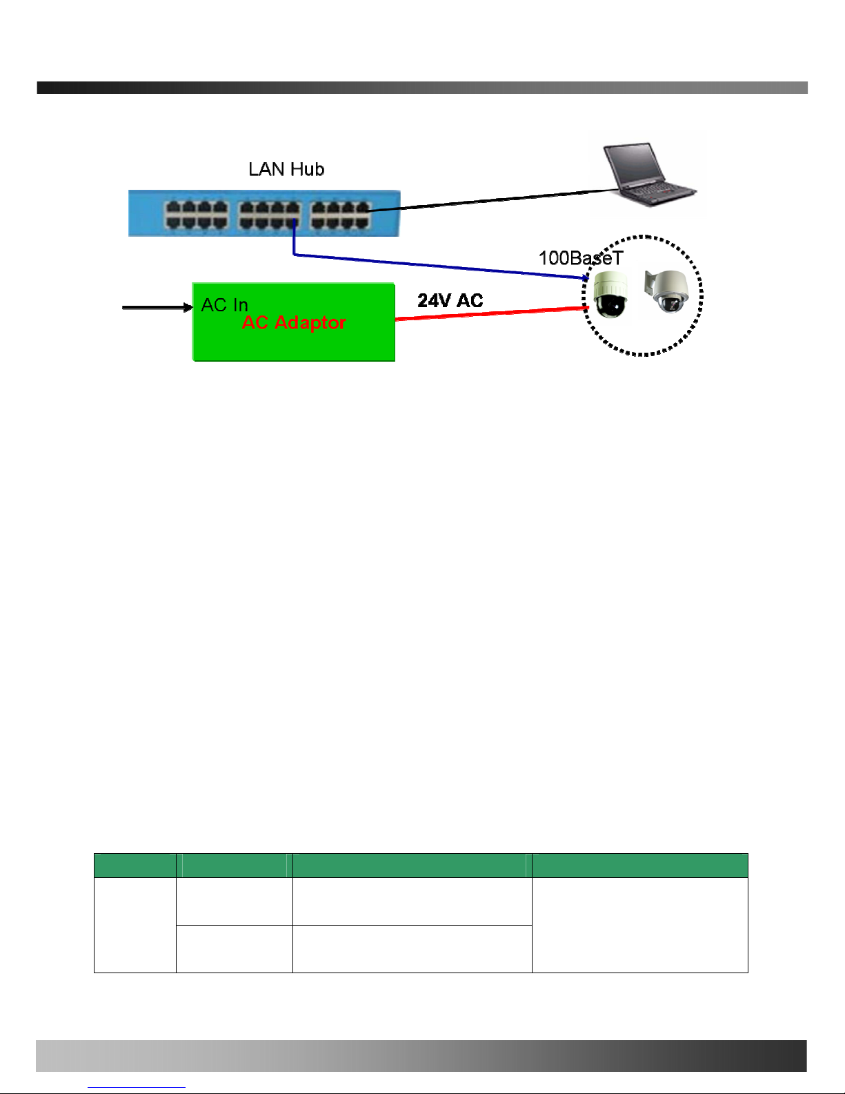
iCanView240/250 User’s Guide
Fig. 2-5 Connecting Network camera and PC
2. Install “IP installer” and “i-NVR” on your PC.
Detailed information for installing these programs can be found in [IP-Installer User’s Guide] and [i-NVR
User’s Guide], respectively.
3. Assign IP address to iCanV iew240/250 using IP installer.
Identify the type of the network environment and set up IP address. Detailed process of setting up IP
address can be found in [IP-Installer User’s Guide]. If network type is xDSL or Cable modem you need
supplementary information provided by your ISP.
4. Connect to iCanVie w240/250 in Administrator Mode for initial parameter set-up.
All parameters are set to factory default state when iCanView240/250 is delivered. You are asked to
configure the system for your environment in administration mode. Detailed information of using
administration mode can be found in [5. Configuring iCanView240/250 in Administrative Mode].
Among the parameters, the parameters in the following table should be set-up with proper values.
Detailed information for the parameters in Administrator Mode is found in [5. Configuring
iCanView240/250 in Administrative Mode]
[Note]: Set-up values are preserved even the power is turned off.
Page Parameter Setup value Factory default value
Video Size
Set the resolution of the video transmitted
from iCanView240/250.
Basic
Setup
Max Upload Rate
Set this value smaller than the upload
speed of your network.
Make sure that you press Check button
to find out the number of maximum
possible simultaneous users then set
the number of users smaller than or
19

iCanView240/250 User’s Guide
Frame Rate
The number of frames to be transmitted per
second.
Video Rate
Bandwidth assigned for video transmitted
from iCanView240/250.
equal to the number.
Administrator name
& password
For safety, you are recommended to
change these values from factory default.
For new connection, you need to input
changed values for corresponding fields.
Do not disclose these values to others and
memorize these values.
Default value
User name : root
Password : dw2001
User
Admin &
Time
Setup
User
Admin &
Time
Setup
Current Time
Input correct time in this field.
Default value :
2001/1/1
5. Connect the input and output signals to iCanView240/250.
Function Signal description Number Connectors
Audio/Voice in
Connect microphone or output from audio
devices.
1
Mic/LINE-In
Line Out
Audio out for
speaker
Audio from remote site is available from this
connector in bi-directional audio mode.
Connect speaker with amplifier.
1
Connecting Alarm
Sensor
IR sensor, Motion Sensor, Smoke
Detector…
1
Alarm
/Aux
Connecting Alarm
annunciating
device
Siren, Flashing Light, … 1
Network connection
Connect iCanView240/250 to the network,
LAN, ADSL or Cable modem.
1
Network
Supply AC power Apply AC24V power to network camera 1
AC24V
6. Remote video connection to iCanView240/250
Run i-NVR on your PC. Before connecting to iCanView240/250 it is needed to configure the connection
information on the i-NVR. More detailed information of using “i-NVR” can be found in [i-NVR User’s
Guide].
20
iCanView240/250 User’s Guide
3. Connecting iCanView240/250 to IP Network
iCanView240/250 supports LAN, xDSL, and Cable modem. It also supports shared IP environment where single
IP address is shared by at least 2 IP devices. Refer to [IP-Installer User’s Guide] for details of setting the IP
address for iCanView240/250.
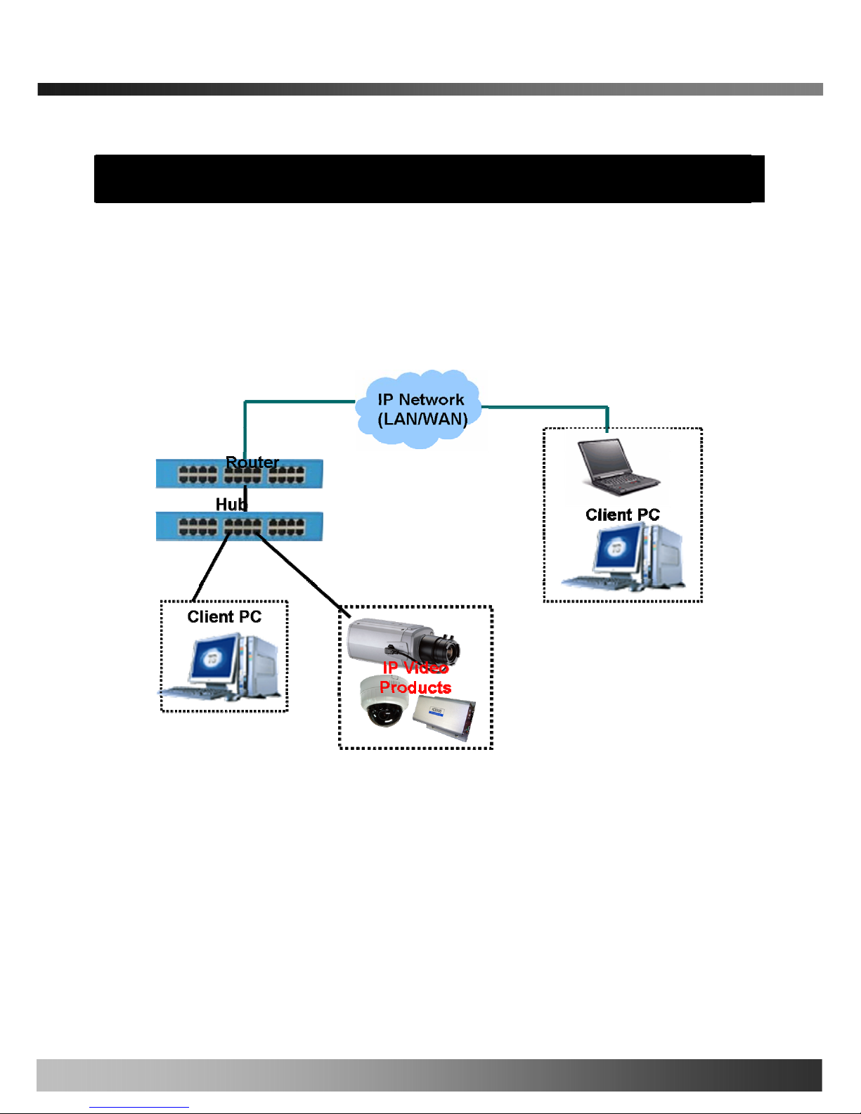
3.1. Connecting to LAN
In case of connecting the iCanView240/250 to LAN, it is generally connected as in Fig. 3-1.
Fig. 3-1 Connecting iCanView240/250 to LAN
1. Follow through steps 1 to 3 in Section 2.6 to assign IP address to iCanView240/250.
2. Check if you can receive video data when connecting to iCanView240/250 using the viewer program.
4. When one or more IP video products are connected through a IP sharing device (i.e. router) to a larger network
(i.e. the internet), in order to access each unit from outside the local area network, each device must have a
unique RTSP (Real Time Stream Protocol) and HTTP port number. You must also conFig. your IP sharing
device for “port forwarding”. This is to enable the IP sharing device to forward packet data with unique port
number (RTSP and HTTP) to unique internal IP address (local IP address). If you only plan to access multiple
units from within a local area network, you do not need to change the RTSP and HTTP port numbers, unless
21
 Loading...