

iCanView232 User’s Guide
Directions
iCanView232 is designed for indoor use only. When using iCanView232 outdoors or in an
environment that exceeds the limited range, you must separately use a water-resistant case.
Be careful not to cause any physical damage by dropping or throwing the iCanView232.
Especially keep the device out of reach from children.
Do not disassemble iCanView232. You will be excluded from After Service when disassembled.
Use only the power adapter provided with the iCanView23 2.
If you would like to use the iCanView232 for security, monitoring, please check the legal
regulations within the country.
`
Rev1.0(Feb. 2008)

iCanView232 User’s Guide
Note
This equipment has been tested and found to comply with the limits for a Class A digital
device, pursuant to part 15 of the FCC Rules. These limits are designed to provide
reasonable protection against harmful interference in a residential installation. This
equipment generate, uses and can radiate radio frequency energy and, if not installed
and used in accordance with the instructions, may cause harmful interference to radio
communications. However, there is no guarantee that interference will not occur in a
particular installation. If this equipment does cause harmful interference to radio or
television reception, which can be determined by turning the equipment off and on, the
user is encouraged to try to correct the interference by one or more of the following
measures :
z Reorient or relocate the receiving antenna.
z Increase the separation between the equipment and receiver.
z Connect the equipment into and outlet on a circuit different from that to which
the receiver is connected
z Consult the dealer or an experienced radio/TV technician for help.
Rev.1.0 (Feb. 2008)
2 of 56

iCanView232 User’s Guide
Any changes or modifications in construction of this device which are not explicitly
approved by the party responsible for compliance could void the user’s authority to operate
the equipment.
Caution
This appliance and its antenna must not be co-located or operating in conju nction with any other
antenna or transmitter. A minimum separation distance of 20 cm must be maintained between the
antenna and the person for this appliance to satisfy the RF exposure requirements.
Revision History
Date Rev No Description
2008-02-13 1.0 Creation of the document
Table of Contents
Rev.1.0 (Feb. 2008)
3 of 56

iCanView232 User’s Guide
1. Introduction ............................................................................................................................................ 5
1.1. Overview .......................................................................................................................... 5
1.2. Features of iCanView232 ............................................................................................... 5
1.3. Applications of iCanView232 ......................................................................................... 6
1.3. Selectable options and model naming convention .................................................... 6
2. Product Description ............................................................................................................................... 8
2.1. Contents .......................................................................................................................... 8
2.2. Preview ............................................................................................................................ 8
2.3. Physical description ........................................................................................................ 8
2.4. PC Requirements .......................................................................................................... 12
2.5 Quick Installation Guide ................................................................................................ 12
3. Connecting iCanView232 to Network ................................................................................................ 16
3.1. Connecting to LAN ........................................................................................................ 16
3.2. Connecting to xDSL/Cable Modem ............................................................................. 17
4. IP-Installer ............................................................................................................................................ 19
4.1. Main window of IP-Installer ........................................................................................ 19
5. Configuring iCanView232 in Administrative Mode ........................................................................... 21
5.1. Log On ............................................................................................................................ 21
5.2. Basic Setup .................................................................................................................... 23
5.3. Network Configuration ................................................................................................. 25
5.4. Wireless Configuration ................................................................................................. 28
5.5. CCD Adjustment ........................................................................................................... 30
5.6. User Admin & Time Setup ........................................................................................... 33
5.7. Sensor & Capture Setup .............................................................................................. 36
5.8. Alarm Device Setup ...................................................................................................... 38
5.9. Motion Region Setup .................................................................................................... 40
5.10. PTZ Setup(Zoom is not applicable for iCanView232) ............................................ 42
5.11. Encryption Set up ....................................................................................................... 44
5.12. Upgrade & Reset ......................................................................................................... 46
5.13. Status Report .............................................................................................................. 48
6. Tips for using iCanView232 ................................................................................................................ 49
6.1. ALARM-IN and ALARM-OUT ......................................................................................... 49
6.2. Trouble Shooting ........................................................................................................... 52
6.3. Web Viewer .................................................................................................................... 53
6.4. How to Upgrade the iCanView232 ............................................................................. 55
Rev.1.0 (Feb. 2008)
4 of 56

iCanView232 User’s Guide
1. Introduction
1.1. Overview
The iCanView232 is a state-of-the-art network camera which transmits synchronized video and
audio data in real time with D1 resolution at full frame rate. This is possible through MPEG4 CODEC
technology, which provides high quality video with highly compressed data streams. The
iCanView232 can be connected, controlled and monitored from a remote location through an IP
connection over internet or intranet. Unlike CCTV or DVR, the iCanView232 is easy to install and
owner will experience cost and space savings in the installation owing to the state of the art
technologies embedded in the system. Based on Embedded Software Solution (Embedded Web
Server, Embedded Streaming Server, Network Protocol), the iCanView232 ensures unprecedented
performance and stability to be an ideal network camera solution for system integration solutions.
To facilitate single cable installation, iCanView232 are offered with standard PoE option (IEEE
802.3af).
1.2. Features of iCanView232
y 1 channel synchronized real time Video/Audio streaming
MPEG-4 video, ADPCM audio.
y Bi-directional audio communication
Real time audio communication between iCanView232 and Client PC
y The viewer assisted recording and playback function s.
y 1 Alarm sensor input/1 relay output
y Motion detection – Up to 3 motion detection zones
Arbitrary shape motion detection zone
Motion detection can initiate video recording, which is sent to the user through F TP and/or E-mail.
y Resolution
- NTSC : 704x480, 352x240, 176x144.
- PAL/SECAM : 704x576, 352x288, 176x144
y RS-485 interface for Pan/Tilt device connection
y Remote administration control
Entire operational parameter set up, Software upgrade
y Embedded WiFi interface (iCanVeiw232W only) – IEEE 802.11b/g
y Standard PoE (802.3af) for single cable wiring of the network and power application.
Rev.1.0 (Feb. 2008)
5 of 56

iCanView232 User’s Guide
1.3. Applications of iCanView232
y Security surveillance (buildings, stores, manufacturing facilities, parking lot s, banks, government
facilities, military, etc.)
y Real time Internet broadcasting
y Remote monitoring (hospitals, kindergartens, traffic, public areas, etc.)
y Teleconference (Bi-directional audio conference)
y Remote Learning
y Weather and environmental observation
1.4. Selectable options and ordering information
For maximizing the application area, iCanView232 can be offered with varieties of options. These
options include various camera modules, lenses or network interface options. Refer to the
following conventions for the selection of the options and model names.
z Naming convention
iCanView232
- WPMT
Basic model Options
Basic model
Basic Model Description Misc
iCanView232 270K Sony CCD, Fixed Lens
iCanView232+ 410K CCD, 480 TV lines, Varifocal
iCanView232++ 410K CCD, 520 TV lines, Varifical
iCanView232SB 410K Sony WDR, Varifocal
iCanView232PB 410K Pixim WDR, Varifocal
Selectable options
Capital letters following the hyphen, “-“ indicate selectable options. Please refer to the
following table for the options. Each capital letter indicates insertion of corresponding
option. Note that there can be multiple capital letters to indicate presence of multiple
options.
Option indicator Description Misc
W Wireless LAN (802.11b/g)
P Standard PoE (IEEE 802.3af)
M Inclusion of embedded flash memory (NAND)
Rev.1.0 (Feb. 2008)
6 of 56

iCanView232 User’s Guide
N True Day/Night – IR cut filter
Rev.1.0 (Feb. 2008)
7 of 56
iCanView232 User’s Guide
2. Product Description
2.1. Contents 2.1. Contents
Open the package and check if you have the followings: Open the package and check if you have the followings:
Components Description Remarks
iCanView232 iCanView232 Network Camera
Power adapter
Input : 100~250V 50-60Hz
Output : +12V, 1.0A
Standard Power supplied
when standard PoE is
not selected
AC power cable AC 250V, 10A~16A
Standard Power cable
supplied when standard
PoE is not selected
Antenna For Wifi option only
CD-ROM Software & User’s Guide
Quick Reference Guide Quick installation guide Will be provided
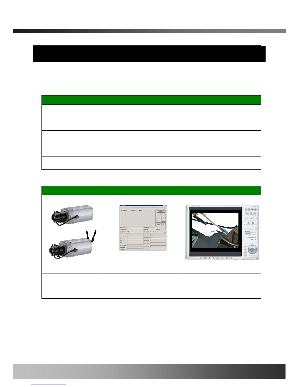
2.2. Preview
iCanView232 IP-Installer i-NVR
1CH MPEG-4 Network
Camera
PC software to allocate an IP
address to the iCanView232
PC software to view and record
the A/V streaming data
transmitted from iCanView232
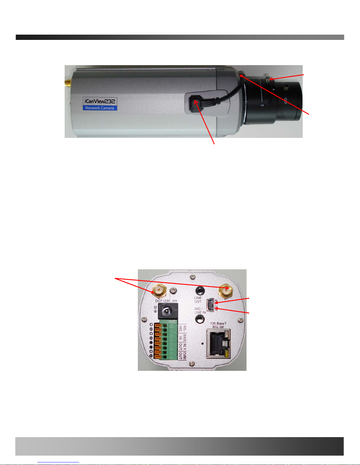
2.3. Physical description
2.3.1. Front View
Rev.1.0 (Feb. 2008)
8 of 56
iCanView232 User’s Guide
Figure 2-1. Side view of iCanView232
y Lens : Standard C or CS type lens can be accommodated into iCanView232. Either fixed or
Varifocal lens can be used with iCanView232.
y Microphone : Picks-up sound from the environment for transmission over the network.
y Auto Iris Control : Plug in the cable from standard DC-Iris lens.
2.3.2. Rear panel
Lens
Microphone
WIFI Antenna
Pin 5
Pin 1
Auto Iris Control
Figure 2-2. Rear views of iCanView232
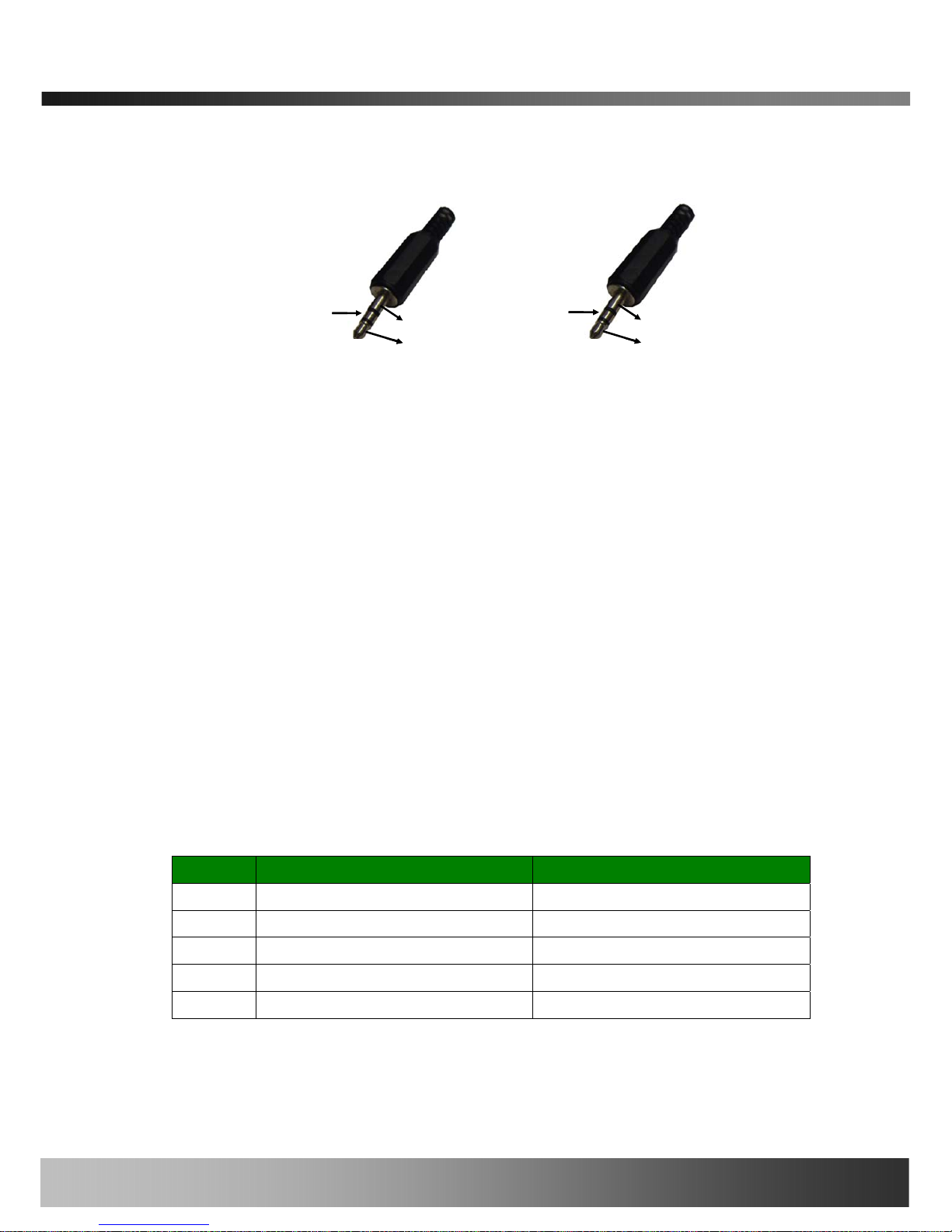
y MIC /LINE IN : Connect external audio source or microphone. If external audio is connected,
Rev.1.0 (Feb. 2008)
9 of 56
iCanView232 User’s Guide
embedded microphone will be disabled.
Use Standard stereo earphone jack for the connection
Audio In
Ground
Not used
Audio In
Ground
Not used
Audio out
Ground
Not used
Audio out
Ground
Not used
Figure 2-3. Pin assignment of the plug for MIC/LINE In (left) and
LINE OUT (right)
y LINE OUT : Connect speakers with built in amplifier. Audio from remote site is output through
Line out in bi-directional audio mode.
Use Standard stereo earphone jack for the connection.
y 100BaseT 802.3af : 100Mbps Ethernet connector (RJ-45) with PoE standard (802.3af).
- LINK LED : Continuous yellow light means that network cable is plugged in. It will flicker
when there is traffic.
- Status LED: Green color indicates that the camera is in normal operation mode, while RED
color indicates that the camera is in abnormal condition.
y RS-232C
3 Pins from the bottom of the connector are assigned for RS-232 port. Please note that the
bottom most pin is numbered as 1.
Pin Description Misc.
1 Not used
2 Not used
3 RxD of RS-232C For debugging & factory use only.
4 TxD of RS-232C For debugging & factory use only.
5 Ground of RS-232C For debugging & factory use only.
y DC7-23V, 8W: Power input of iCanView232.
Do not apply power through this power input when Stan dard PoE connection is used.
Rev.1.0 (Feb. 2008)
10 of 56

iCanView232 User’s Guide
y RS-485, ALARM IN/OUT, Composite Video Output : Used for connecting P/T device,
sensor, and alarm devices to iCanView232. Note that the bottom most pin is numbered as 1. Pin
assignments are as follows
Pin Description Misc.
1 RS-485 Plus (+) For providing RS485 signal to RS485
devices
2 RS-485 Minus (-) For providing RS485 signal to RS485
devices
3 SNS IN (+) Sensor In (+). NC/NO selectable in
admin mode.
4 SNS In (-) Sensor In (-). NC/NO selectable in
admin mode.
5 RLY OUT Relay output : closed circuit in alarm
to indicate alarm status.
6 RLY OUT
7 CVBS OUT(+) Composite output of analog video
8 CVBS OUT(-) Ground connection for Composite
output of analog video
RS-485 : Used for connecting Pan/Tilt and Zoom devices having RS-485 interface
standard.
SNS IN : Connect external alarm sensors such as the infrared sensors, heat sensor,
magnetic sensors, etc. NC/NO selectable in the admin page.
RLY OUT : It is used for connecting external alarm generators such as sirens,
flashing light, etc. When activated, relay output configures a closed circuit.
Please refer to Section 6.1 for more detailed description on the Alarm In/Out
connections.
y Reset : Factory Default Switch
There is a switch provided for returning the network camera to factory default state. Press the
switch through a tiny hole at the left of the 100BaseT connector using tools with sharp tip for a
few seconds while power is applied.
y WIFI antenna Connector : Available only when the WIFI option is selected. Connector for
Rev.1.0 (Feb. 2008)
11 of 56

iCanView232 User’s Guide
connecting 3dBi antenna supplied with iCanView232
2.4. PC Requirements
AV streaming data received from iCanView232 can be decoded or stored in a PC running i-NVR
program which is a viewing & recording program for a PC. Minimum requirement of the PC is
described below:
Minimum Recommended
CPU Pentium III 700 Pentium IV 2GHz above
Main Memory 128 MB 512MB above
Operating system* Windows 2,000 or later Windows XP
Web browser Internet Explorer 5.0 Internet Explorer 6.0 above
Graphic Card Onboard VGA Ati Radeon Series
Network 10 Base-T Ethernet 100 Base-T Ethernet
* Operating Systems supported : Windows 2000 Professional
Windows XP Professional / Windows XP Home Edition
2.5 Quick Installation Guide
Brief information for rapid installation is provided in this section. For more detailed information you
are recommended to refer to pertinent documentations provided with the product or refer to
iCanTek’s home page (http://www.icantek.com)
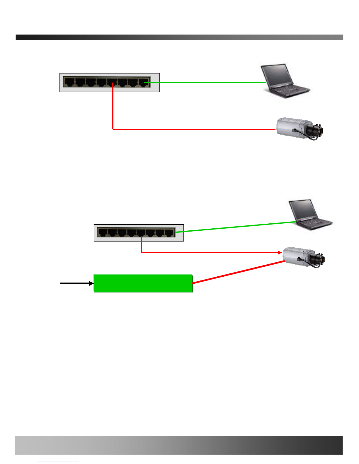
1. Connect iCanView232 to LAN by using one of the following method
1) If your iCanView232 has standard PoE option, connect the network camera and PC as
illustrated in Figure 2.4. Both power and network connections are made with a single LAN
cable. Make sure that you are using hub supporting standard PoE (802.3af).
2) If your iCanView232 does not support standard PoE or you don’t have hub supporting
standard PoE, connect iCanView232 as in Figure 2.5. The DC power is applied through AC
adaptor.
2) If you have standard power connect the network camera and PC as illustrated in Figure
2.6.
Rev.1.0 (Feb. 2008)
12 of 56
Standard PoE Hub
iCanView232 User’s Guide
Figure 2-4. Connecting Network camera using Standard PoE (802.3af).
AC A
daptor
Hub
AC In
100BaseT
DC In
Figure 2-5. Conventional way of connecting network camera without standard PoE.
<Caution>
When power is applied through standard PoE, never apply power through AC
adaptor. iCantek assumes no responsibility for the damages caused by collision of
the power through the standard PoE and AC adaptor.
2. Install “IP installer” and “i-NVR” on your PC.
Detailed information for installing these programs can be found in [IP-Installer User’s
Guide] and [i-NVR User’s Guide], respectively.
Rev.1.0 (Feb. 2008)
13 of 56

iCanView232 User’s Guide
3. Assign IP address to iCanView232 using IP installer.
Identify the type of the network environment and set up IP address. Detailed process of
setting up IP address can be found in [IP-Installer User’s Guide]. If network type is
xDSL or Cable modem you need supplementary information provided by your ISP.
4. Connect to iCanView232 in Administrator Mode for initial parameter set-up.
All parameters are set to factory default state when iCanView232 is delivered. You are
asked to configure the system for your environment in administration mode. Detailed
information of using administration mode can be found in [5. Configuring iCanView232
in Administrative Mode]. Among the parameters, the parameters in the following table
should be set-up with proper values. Detailed information for the parameters in
Administrator Mode is found in [5. Configuring iCanView232 in Administrative Mode]
[Note]: Set-up values are preserved even the power is turned off.
Page Parameter Setup value Factory default value
Basic Setup
Video Size
Set the resolution of the video
transmitted from iCanView232.
Make sure that you press Check
button to find out the number of
maximum possible simultaneous
sers then set the number of
users smaller than or equal to the
mber.
u
nu
Max Upload Rate
Set this value smaller than the upload
speed of your network.
Frame Rate
The number of frames to be
transmitted per second.
Video Rate
Bandwidth assigned for video
transmitted from iCanView232.
User Admin
& Time
Setup
Administrator
name &
password
For safety, you are recommended to
change these values from factory
default. For new connection, you need
to input changed values for
corresponding fields. Do not disclose
these values to others and memorize
these values.
Default value
Username : root
Password : dw2001
User Admin
& Time
Setup
Current Time
Input correct time in this field.
Default value :
2001/1/1
5. Connect the input and output signals to iCanView232.
Rev.1.0 (Feb. 2008)
14 of 56

iCanView232 User’s Guide
Connectors Function Signal description Number
LINE-
In/MIC
Audio in
Connect microphone or output from
audio devices.
1
Line Out
Audio out for
speaker
Audio from remote site is available
from this connector in bi-directional
audio mode. Connect speaker with
amplifier.
1
SENS IN
Connecting
Alarm Sensor
IR sensor, Motion Sensor, Smoke
Detector…
1
RLY OUT
Connecting
Alarm
annunciating
device
Siren, Flashing Light, … 1
RS485 PT device control
Remote P/T/Z device connection
having RS485 interface.
1
100Base-T
802.3af
Network
connection
Connect iCanView232 to the network,
LAN, ADSL or Cable modem.
1
CVBS OUT
Analog Video
output
Composite video output from the
camera module.
1
6. Remote video connection to iCanView232
Run i-NVR on your PC. Before connecting to iCanView232 it is needed to configure the
connection information on the i-NVR. More detailed information of using “i-NVR” can be
found in [i-NVR User’s Guide].
Rev.1.0 (Feb. 2008)
15 of 56

iCanView232 User’s Guide
3. Connecting iCanView232 to Network
iCanView232 supports LAN, xDSL, and Cable modem. It also supports shared IP environment
where single IP address is shared by at least 2 IP devices. Refer to [IP-Installer User’s Guide]
for details of setting the IP address for iCanView232.
iCanView232 supports LAN, xDSL, and Cable modem. It also supports shared IP environment
where single IP address is shared by at least 2 IP devices. Refer to [IP-Installer User’s Guide]
for details of setting the IP address for iCanView232.
3.1. Connecting to LAN 3.1. Connecting to LAN
In case of connecting the iCanView232 to LAN, it is generally connected as in Figure 3-1. In case of connecting the iCanView232 to LAN, it is generally connected as in Figure 3-1.
Figure 3-1. Connecting the iCanView232 to LAN Figure 3-1. Connecting the iCanView232 to LAN
1. Follow through steps 1 to 3 in Section 2.5 to assign IP address to iCanView232. 1. Follow through steps 1 to 3 in Section 2.5 to assign IP address to iCanView232.
2. Install iCanView232 and connect it to desired LAN. 2. Install iCanView232 and connect it to desired LAN.
3. Check if you can receive video data when connecting to iCanView232 using the viewer program. 3. Check if you can receive video data when connecting to iCanView232 using the viewer program.
4. When one or more IP video products are connected through a IP sharing device (i.e. router) to a
larger network (i.e. the internet), in order to access each unit from outside the local area network,
each device must have a unique RTSP (Real Time Stream Protocol) and HTTP port number. You
must also configure your IP sharing device for “port forwarding”. This is to enable the IP sharing
device to forward packet data with unique port number (RTSP and HTTP) to unique internal IP
address (local IP address). If you only plan to access multiple units from within a local area
Rev.1.0 (Feb. 2008)
16 of 56
iCanView232 User’s Guide
network, you do not need to change the RTSP and HTTP port numbers, unless other IP sharing
devices sit in-between the client and the IP video products. For more detailed information
regarding the use of IP sharing device refer to the document [Use of Private IP network using
IP-sharing-device].
②
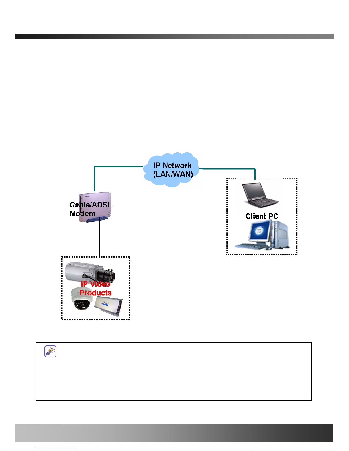
3.2. Connecting to xDSL/Cable Modem
1. Follow through steps 1 to 3 in Section 2.5 to assign IP address and other network parameters to
iCanView232.
2. Install iCanView232 and connect it to xDSL or Cable modem as in Figure 3-2.
Figure 3-2. Connecting the iCanView232 to ADSL Modem
When fixed IP address is assigned to the xDSL or Cable modem, follow the same way as
assigning IP address for the case of LAN using IP-installer. To enable the notification of the
changed IP address to the user over e-mail when the IP address is changed in floating IP
environment, you have to assign the e-mail address when user name and password are
input using IP-installer. (Management server provides a convenient way of
Rev.1.0 (Feb. 2008)
17 of 56

iCanView232 User’s Guide
connecting to your network camera under dynamic IP environment. Please refer
to the Application note regarding “Management Server” in the CD.)
When connecting iCanView232 to xDSL or Cable modem, usually regular LAN cable is
required. But since some modems have crossover connections, please contact your
service provider for detailed information.
Rev.1.0 (Feb. 2008)
18 of 56

iCanView232 User’s Guide
4. IP-Installer
iCanView232 needs IP network parameters for connection to the network(Internet/Intranet). IPInstaller is a PC program for the initial network configuration to IP video products such as Network
Camera or A/V Server. IP-Installer is provided in a CD supplied with iCanView232 or it can be
downloaded from “www.icantek.com
”.
Detailed information of Installing and running IP-installer can be found in [IP-installer
user’s guide]
4.1. Main window of IP-Installer
Figure 4-1. IP Installer
All the basic network parameters needed for the initial connection to IP video products can be
Rev.1.0 (Feb. 2008)
19 of 56

iCanView232 User’s Guide
assigned by IP-Installer. Once the basic parameters are assigned and the initial connection is
successfully made, you can connect to the administration page for more sophisticated control of
the network parameters and other operational parameters. Refer to Chapter 5 for more details of
the administration page.
Rev.1.0 (Feb. 2008)
20 of 56

iCanView232 User’s Guide
5. Configuring iCanView232 in Administrative Mode
5.1. Log On
There are 2 ways of connecting to iCanView232 administrative mode. One is through Internet
Explorer and the other is through “i-NVR” program.
1. Using Internet Explorer
Type in the connection address of the network camera in the address window of the Internet
Explorer as followings:
http://[iCanView232 IP address]/admin.htm
Example: http://172.16.64.133/admin.htm
If you changed the HTTP port from default value you can login by typing in:
http://[iCanView232 IP address]:[HTTP port]/admin.htm
Example: http://172.16.64.133:8080/admin.htm
2. Log on from “i-NVR”
Select video channel in the viewing window of “i-NVR”. Selected video channel will be
highlighted. Click button on the right side of the display screen.
Figure 5-1. Select display channel and click “Camera Admin” button for Log on to
administrative mode from “i-NVR”
3. Input User Name and Password in the display screen shown in Figure 5-2.
Rev.1.0 (Feb. 2008)
21 of 56

iCanView232 User’s Guide
Figure 5-2. Log On Screen
Factory default User Name and Password are set as ‘root’ and ‘dw2001’, respectively. Click on “OK”
button to enter into the Basic Setup page of Administrative M ode. If you have changed th e username
and password of the Administrator, you must log on with the changed username and password.
Rev.1.0 (Feb. 2008)
22 of 56

iCanView232 User’s Guide
5.2. Basic Setup
Setup the basic parameters of the iCanView232.
Figure 5-3. Basic Setup
Field/Button
Sub Field
/Button
Description
Language
Select a language of your choice
System Name
Logical name of the iCanView232. It is same as the one set-up
by IP-installer. You can reassign the system name.
Rev.1.0 (Feb. 2008)
23 of 56

iCanView232 User’s Guide
Audio Input
Selection
Select the type of input audio.
z Select Line In for using Line-out from audio devices.
z Select Mic for using microphone.
Video Quality
& Bandwidth
Control
Input Video This filed is set by the factory
Video Size
Select a video size for transmission-
z NTSC(30 frames/sec Max.) : 176x144 / 352x240 /
720x480.
z PAL/SECAM (25 frames/sec Max.) : 176x144 /
352x288 / 720x576
Max upload
rate
Assign maximum bandwidth of the uplink for the network
connected to iCanView232.
Frame rate
Assign number of video frames to be transmitted for each
second. You can improve picture quality by lowering frame
rate for the same bandwidth.
Video rate Assign bandwidth for transmitting video data.
Audio rate
Assign bandwidth for transmitting audio data. Audio data is
not transmitted if you select “NA”
Check
After you finish set up of video and audio for all the channels,
click on this box to obtain the possible maximum number of
users (Possible Max Users) and remaining network
bandwidth (Remained) remaining when possible maximum
users are connected.
Possible Max
Users
It shows the number of maximum simultaneous connections
for the network connection set-up.
Remained
It shows the network bandwidth remaining when Possible Max
Users are connected.
Limited users
Useful network bandwidth varies according to the condition of
the network. This parameter is used to limit the number of the
simultaneous connections below the number shown in Possible
Max Users.
Save
Save the set-up parameters when the set-up parameters are
done.
Rev.1.0 (Feb. 2008)
24 of 56

iCanView232 User’s Guide
5.3. Network Configuration
Setup the network parameters appropriately in accordance with your network environment. Many
of the parameters in this page are same as those set up by “IP-Installer”.
Figure 5-4. Network Configuration
Rev.1.0 (Feb. 2008)
25 of 56

iCanView232 User’s Guide
Field/Button
Sub Field
/Button
Description
IP Assign Type
The network types supported by the iCanView232 are
LAN(fixed IP), PPPoE, and DHCP(automatic IP allocation)
Static IP
Setup
When the network environment is fixed IP, select ‘LAN’ in the
network type, and put the IP address, Subnet Mask, Gateway,
DNS1 and DNS2. Ask your network administrator or ISP for the
information. DNS2 is used when DNS1 does not work.
PPPoE Setup
When the network environment is PPPoE and IP address is
assigned automatically, select ‘PPPoE’ in the network type.
Next, fill in the ‘User Name’ and ‘Password’ fields with the
values assigned by the ISP.
DHCP Setup
When the network environment is “automatic IP allocation by
DHCP”, select ‘DHCP’ in the network type. For cable modem
connection, select this mode.
Refer to [IP-installer user’s guide] for “Host name and
domain for Cable Modem
Clone MAC Refer to [IP-installer user’s guide] for “Clone MAC”
Port Change
Each port should have a number below 65535.
RTSP
The RTSP port is used for transmitting real time audio/video
data from the network camera. Default is 554.
HTTP
HTTP port is used for the connection to the admin page.
Default is 80.
IP Filtering
You can restrict the access to the administrator page from IP
addresses beyond certain IP address range.
Restrict
Administrator
Access
Check at this box to restrict administrative log on.
Base IP
Address
Input IP address of the PC which is intended to be used for log
on to administrative mode.
Mask
This is same as subnet mask. It is used to allow administrative
log on only to the PCs located in the same subnet as the base
IP address. If you want to allow only one PC to access in
administrative mode, set this value to 255.255.255.255.
E-Mail Setup
Rev.1.0 (Feb. 2008)
26 of 56

iCanView232 User’s Guide
Notify for IP
Change
If you check this, the IP address will be sent via E-mail
whenever the IP address changes. It is sent to the E-mail
address set by “Recv E-Mail Address”.
Recv E-Mail
Address
Enter E-mail address to receive information sent from your
network camera. This is same as E-mail field in IP-installer.
Return E-Mail
Address
Fill in this field with correct e-mail address to identify the mail
sent from the network camera
Using Built-in
SMTP Server
If you are using web mail services having no SMTP server,
check the radio button at the left of “Using Built-in SMTP
Server” and enter valid e-mail address to avoid spam filtering
on the receiving e-mail server.
Using
External
SMTP Server
If you are using external mail server, fill in the fields with
proper parameters.
FTP Server
Setup
Setup IP address, Username, Password and Directory of FTP
server to send data in case of alarm. Default FTP port number
is 21.
Management
Server
You can register the network camera to the Management
Server (DDNS Server) for name service to your network
camera.
Log on to
server
Check this box to enable log on to the management server. By
log on to the management server your network camera can use
domain name instead of numeric IP address. This feature is
particularly useful when your network camera is using dynamic
IP address. Input valid management server (DDNS Server)
name for the service.
You must have an account on the management server (DDNS
Server) and register your IP video devices under your account
to use this feature.
Domain name of your network camera can be assigned when
you register your network camera to the management server
under your account.
One of the servers available is mgmt.net-video.net. For
opening an account, visit www.net-video.net
.
Rev.1.0 (Feb. 2008)
27 of 56

iCanView232 User’s Guide
5.4. Wireless Configuration
For the case of a network camera having built in wireless LAN it is needed to set up wireless LAN
configuration parameters. Click “Wireless Configuration”.
Figure 5-5 Wireless Configuration
Field/Button
Sub Field
/Button
Description
Wireless LAN
Setup
WLAN Mode
Select “ESS” to use wireless interface. If “Disable” is selected,
Ethernet interface is used instead of wireless LAN interface.
WLAN Radio Select the mode of Wireless Radio.
SSID
Enter the ID of the wireless LAN access point to be connected
when wireless LAN interface is selected.
Authentication Select the type of authentication.
Encryption Select the mode of encryption. If encryption is not needed,
Rev.1.0 (Feb. 2008)
28 of 56

iCanView232 User’s Guide
select “OFF”
Key Set the value of encryption key or pre-shared key.
Power level Set the maximum transmission power level or wireless LAN.
WLAN
Information
MAC Address Indicates MAC address of the wireless LAN.
BSSID
Indicates the ID of the connected access point. In general the
MAC address of the access point is shown.
Current
Channel
Indicates the channel number of present connection.
Signal
Strength
Indicates the strength of the received signal.
Link Quality Indicates the quality of Link level.
Tx Rate Indicates the speed of the latest transmission
Rev.1.0 (Feb. 2008)
29 of 56

iCanView232 User’s Guide
5.5. CCD Adjustment
You can optimize the quality of input video by adjusting the parameter of CCD. To enter into
this mode, click “CCD Adjustment” in administrative page. You will find a screen shown in
Figure 5-6.
Figure 5-6. CCD Adjustment
Field/Button
Sub Field
/Button
Description
Lens Selection
Standard iCanView232 is delivered without lens. Any lens
having C or CS mount type can be installed on iCanView232.
Rev.1.0 (Feb. 2008)
30 of 56

iCanView232 User’s Guide
A C-CS adaptor is packaged with iCanView232 for
accommodating CS type lens.
Confirm whether your lens is Non DC IRIS or DC IRIS lens
before your selection and then click “SAVE” to save your
selection.
DC IRIS Lens
DC IRIS lens is a kind of auto IRIS lens. Opening of IRIS can
be adjusted by applying DC voltage. The opening of IRIS is
optimally adjusted by detecting the signal level from CCD. This
type should be selected when DC IRIS lens is mounted on your
iCanView232.
ELC Manual Lens without IRIS control
CCD Control
Backlight
Compensation
When the camera is acquiring video from object with bright
backlight, it is hard to identify the details of target object since
the object appears very dark. Apply backlight compensation
mode for this case. Default mode is backlight compensation
Off.
Auto Gain
Control
If you set the value to ON, the gain is automatically adjusted in
accordance with the illumination condition.
Flickerless
In case of using NTSC type iCanView232 in 50Hz AC regions or
using PAL type iCanView232 in 60Hz AC region, video output
tends to flicker when iCanView232 is used under fluorescent
lamps. This mode reduces the flickering phenomena. If this
mode is selected, electronic shutter speed is set to 1/100 sec
for NTSC camera while it is set to 1/120 for PAL camera to
synchronize the shutter speed to AC current.
<Note> : Make sure that you apply this mode only when using
NTSC camera in PAL region or PAL camera in NTSC region.
AWB
AWC : Apply this mode for normal usage. This mode provides
even color reproduction for wide range of color temperature.
ATW : This mode provides coverage for narrower color
temperature.
Sharpness Adjust the sharpness of the video
D C level Adjust the brightness level by adjust this value.
Color Blue Adjust the amount of blue in the video.
Color Red Adjust the amount of red in the video
Restore Apply original sett in g of the valu es.
Rev.1.0 (Feb. 2008)
31 of 56

iCanView232 User’s Guide
Original Values
SAVE Click “SAVE” to save your selection.
Rev.1.0 (Feb. 2008)
32 of 56

iCanView232 User’s Guide
5.6. User Admin & Time Setup
You can change the ID and password of users and also assign different attributes for each user.
Figure 5-7. User Admin. & Time Setup
Field/Button
Sub Field
/Button
Description
Rev.1.0 (Feb. 2008)
33 of 56

iCanView232 User’s Guide
User
Administration
Administrator
Username
Admin ID. Default ID is “root”
Administrator
password :
Admin password. The default password is “dw2001”.
Administrator
Confirm
Password
Enter the password once more to confirm the password.
Add User
Username
Enter the user ID you want to add. Up to 100 users are
supported by iCanView232.
Add User
Password
Enter the user password.
Add User
Attribute
You can set different system resource access capabilities for
each of the users.
z Attributes are Audio, Bi-directional Audio and Pan/Tilt
control.
z For example, if you want a specified user to hear the
audio from the iCanView232, check Audio in the check
box.
User List
You can list “user ids” and “ their attributes” here.
z format : user id[A, BA, P] :
A – audio,
B – bi-directional audio,
P – pt(Pan/Tilt), attribute.
You can delete specific user by clicking the DELETE button.
Authentication
for Viewing
YES
SAVE
If you want to restrict viewing access to the iCanView232, check
at the box left to Yes and click on Save. Users need to input ID
and password to connect to iCanView232 in viewing mode in a
pop up window as shown below..
Figure 5-8. User Authentication in iCanView232
Rev.1.0 (Feb. 2008)
34 of 56

iCanView232 User’s Guide
If No, default
attribute
If you uncheck for the Authentication for Viewing, all users can
access the iCanView232 with the same attribute set here.
Checked attributes are enabled. Click “Save” to save the
attribute.
Time Setup
Current Time It shows you the current time of iCanView232.
Synchronize
with an
Internet
Time Server
Synchronize the time with the internet time server at the right.
When the time server is out of the reach from iCanView232, you
can assign time server by filling in Specific Time Server field.
Synchronize
With this
Computer
Time
Synchronize the time with the time of the PC.
Set Manually Set the time manually. Fill in the fields with desired formats.
SAVE Save the set up parameters
If you lost Administrator’s ID and password, the only means of recovery is to reset
the settings to factory default, but then you lose your previous settings.
Rev.1.0 (Feb. 2008)
35 of 56

iCanView232 User’s Guide
5.7. Sensor & Capture Setup
This is the setup page for sensors and video capture conditions. Captured video can be sent to user
by FTP or E-mail upon configuration.
Figure 5-9. Sensor & Capture Setup
Field/Button
Sub Field
/Button
Description
Sensor Setup
Sensor 1
Select sensor type. There are two types of sensors which are
Normal Open and Normal Close.
Name
Input logical name for the sensor.
Video Capture
Condition
It sets the condition of video transmission via FTP or E-mail.
The iCanView232 supports 2 types of conditions which are
mutually independent.
1. Sensor initiated: when at least one of the sensor
detects alarm condition.
Rev.1.0 (Feb. 2008)
36 of 56

iCanView232 User’s Guide
2. Motion-Detection initiated : when motion is
detected from video channel
Sensor
Select
Check to enable Sensor initiated capture.
Motion
Detection
Select
Check to enable motion detection initiated capture.
Captured
Video
Transmission
Select a way of sending captured video. You can send captured
video through FTP or E-mail, or both.
-
By E-Mail
Check to send captured video by e-mail.
E-mail is sent to the Recv E-mail address. Refe r to [Section
5.3.]
Captured video data for E-mail consists of intra frames only in
consideration of the limited storage space for E-mail account.
FTP data contains entire video frames.
By FTP
Check to send captured video by FTP.
FTP is sent to the FTP Server. Refer to [Section 5.3.]
If the FTP server is not properly assigned in “Network
Configuration” mode, iCanView232 ignores the video
transmission by FTP
SAVE Save the setup parameters.
Rev.1.0 (Feb. 2008)
37 of 56

iCanView232 User’s Guide
5.8. Alarm Device Setup
Test the alarm output and describe the condition of alarm annunciation.
Figure 5-10. Alarm Output Setup
Field/Button
Sub Field
/Button
Description
Alarm Device
Test
Test alarm devices. Click on On/Off for testing
Small box with white background indicates the status of the
relay by On/Off.
ON On the alarm output (close the relay contact)
OFF Off the alarm output (Open the relay contact)
Sound Test -
Alarm Device
Active
Condition
Setup the condition of activating alarm device. Select sensor or
motion detection as the condition.
Name
Logical name of the alarm device can be input into the box at
the left.
Rev.1.0 (Feb. 2008)
38 of 56

iCanView232 User’s Guide
Sensor
Check at the box at the left of to allow alarm generation upon
sensor input.
Motion
Check at the box at the left to allow alarm generation upon
Motion detection
Duration
Set the duration of Alarm annunciation.
10 sec, 30 sec, 1 min, 2 min, 5 min, 10 min, 30 min, 1 hour.
SAVE Save the setup parameters.
Rev.1.0 (Feb. 2008)
39 of 56

iCanView232 User’s Guide
5.9. Motion Region Setup
Set the motion detection regions. Up to 3 regions can be defined.
Figure 5-11. Motion Region Setup
Field/Button
Sub Field
/Button
Description
Channel
Selection
Not applicable.
Channel
Sensitivity
Set the sensitivity in motion detection for each channel. 1 is the
most sensitive, and 10 is the least sensitive.
Rev.1.0 (Feb. 2008)
40 of 56

iCanView232 User’s Guide
Motion Region
Setup
Set up to 3 the motion detection zone
Region 1, 2,
or 3
Enable each zone by checking the box at the left of each Region.
. To set the region,
1. Click on START and click on a box overlaid on the
video
2. Click on END and click on a box overlaid on the video.
3. The defined motion detection zone will be indicated
with corresponding colors.
Legend of the color :
red(region 1),
green(region 2),
blue(region3).
START Enable selection of rectangular zone start.
END Enable selection of rectangular zone end.
SELECT Click on this button and click on desired rectangle to add or delete
the rectangular region to the motion detection zone.
Percentage This value controls the sensitivity of each region.
1 is the most sensitive and 100 is the least sensitive
RESET Clears the start & end point to (0,0) & (0,0)
SAVE Save the setup parameters.
Rev.1.0 (Feb. 2008)
41 of 56

iCanView232 User’s Guide
5.10. PTZ Setup(Zoom is not applicable for iCanView232)
Setup and test the PT(Pan/Tilt ) devices.
Figure 5-12. PTZ Setup
Field/Button
Sub Field
/Button
Description
Channel
Selection
Not applicable
PTZ Model Choose the PT model.
Rev.1.0 (Feb. 2008)
42 of 56

iCanView232 User’s Guide
Selection Refer to section 5.12 for the addition of PT protocol data.
Delete
Button
Press this button to delete the setup of PT
PTZ Device ID
Your PT device needs an ID, input ID in this field.
Click on SAVE to save the ID.
Note that zoom is not applicable for iCanView232.
PTZ Operation
Check
You can check the various operation of the PT devices.
“Left”/”Right”/”UP”/”DOWN”
PTZ Position
Setup
You can set up the PTZ limitation & preset positions if the PT
device supports it.
Panning
Limitation
Set the left/right limitation and t est.
Select Left/Right position before setting.
Panning
Limitation
RESET
Clear the panning limitation previously set.
The panning range will be the same as the PT device allows.
Panning
Limitation
SET
Set the present position as left or right panning limitation.
Panning
Limitation
TEST
Test the panning limitation which was set previously.
Preset
Position :
Set the preset position and test.
Preset
Position
Preset &
Move
Select a preset position to move to. Movement to the preset
position will be made upon clicking on “MOVE”
Preset
Position
Name Set
Assign logical name for the preset position. Enter into the field
and click on SET.
Preset
Position
Set
Set the present position as a preset position with position number
shown at the right of “Preset & Move” and name shown at the
right of “Name Set”.
<Note> : “PTZ Position Setup” feature is applicable only for the PT devices that support it.
Rev.1.0 (Feb. 2008)
43 of 56

iCanView232 User’s Guide
5.11. Encryption Set up
Figure 5-13. Encryption Setup
For additional security to the video and audio data transmitted from the network camera, you can
set key codes and use them for encrypting the data from the network camera.
You can selectively activate encryption for the video and audio data. For enabling the encryption,
check at the box at the left of the “Enable data encryption” then check at the proper check boxes at
the left of “Video” and “Audio”. After the selection, click on SAVE button beneath the “Video” and
“Audio” check boxes.
Field/Button
Sub Field
/Button
Description
Rev.1.0 (Feb. 2008)
44 of 56

iCanView232 User’s Guide
Enable Data
Encryption
Check at this box to apply data encryption.
If it is unchecked encryption is applied on neither video nor
audio data regardless of the selection below.
Video Check to enable encryption on the video data.
Audio Check to enable encryption on the audio data.
SAVE After the selection, click on SAVE button.
Key Value
You can use up to 20 different key codes for the encryption of
the data
GENERATE
To generate the key value click on “GENERATE” button. The
boxes for the Key values will be filled with new values.
SAVE
Save Key value on the network camera: Click on SAVE
button beneath GENERATE button to save the key value
generated by the network camera.
DOWNLOAD
Download Key value to your PC : The key values can be
downloaded and stored as a file to your PC for reference when
you make connection. When encryption is enabled, the PC
client program will ask for particular key value out of the 20
available key values.
INSTALL
Upload key value to the ne twork camera : The key value
stored on your PC can be uploaded to your network camera.
This feature is useful when you manage multiple network
cameras having same key value sets. Select a file having key
values then click on “INSTALL” button to upload the key values.
Find file saving the Key value before uploading to the network
camera.
Rev.1.0 (Feb. 2008)
45 of 56

iCanView232 User’s Guide
5.12. Upgrade & Reset
You can upgrade the iCanView232 via the IP network.
Figure 5-14. Upgrade & Reset
For each of the upgrade of the system component, upgrade code should be downloaded from
iCanTek’s home page before the system upgrade is performed.
(Refer to [6.4. How to Upgrade Your iC anView232 System]
Field/Button
Sub Field
/Button
Description
Automatic
Upgrade
Automatic upgrade is a feature that enables network camera to
upgrade to newly released system software by automatically
connecting to upgrade server. Click on check button to find the
availability of upgrade firmware.
Note that automatic upgrade is not supported for
Rev.1.0 (Feb. 2008)
46 of 56

iCanView232 User’s Guide
standard product.
Manual
Upgrade
Upgrade the system manually.
System S/W
Upgrade
Upgrade the system software installed in the network camera
via the network. System software needed for the upgrade can
be downloaded from iCanTek’s home page.
Refer to [6.4. How To Upgrade Your iCanView232
System].
Bootloader
Upgrade
Upgrade the bootloader installed in the network camera via the
network. Bootloader needed for the upgrade can be
downloaded from iCanTek’s home page.
Refer to [6.4. How To Upgrade Your iCanView232
System].
Add PTZ File
Add a new PT driver software via the network. PT driver can be
downloaded from iCanTek’s home page.
Refer to [6.4. How To Upgrade Your iCanView232
System].
Factory
Default
Setting
Re-initialize the network camera to factory default state.
By checking on a Radio button “Except Network Configuration”,
you can preserve the parameters for the network. Checking on
“All”, will return all the parameters to factory default state.
Once iCanView232 is re-initialized as factory default
state, it should be set-up again using IP-Installer.
System Reset
Perform remote reset by clicking the “CONFIRM” button.
All previous connections will be disconnected upon
reset. iCanView232 does not resume the connections
and the users must re-connect to the server manually.
Rev.1.0 (Feb. 2008)
47 of 56

iCanView232 User’s Guide
5.13. Status Report
It shows you system records since the system started.
Figure 5-15. Status Report
You can check the problems as well as the versions and event status of the whole system and each
module.
Rev.1.0 (Feb. 2008)
48 of 56

iCanView232 User’s Guide
6. Tips for using iCanView232
6.1. ALARM-IN and ALARM-OUT
ALARM connectors are used to connect various sensing and alerting devices. Examples of sensing
devices are infrared sensors, motion sensors, heat/smoke sensors, magnetic sensor, etc. ALARMOUT is used for connecting alerting device such as loud speaker, flashing light, etc.
Figure 6-1. Terminal block for I/O connection
1. ALARM-IN
Connect the two wires of the sensors to “SNS IN”. The sensor type can be set in
Administrative mode(Ref. 5.7). Output lines providing on-off switching are connected
between “+“ and “-” pins.
Figure 6-2 shows the input circuit of “SNS IN”.
Rev.1.0 (Feb. 2008)
49 of 56

iCanView232 User’s Guide
SNS IN (+)
SNS
IN (-)
Figure 6-2. SENSOR input of iCanView232
2. ALARM-OUT
A Relay output is provided for connecting alarm devices or for remote on/off devices
such as light control. Relay circuits are normal open and circuits are closed upon alarm
output or remote on. The relay is capable of switching AC/DC 30V,1A electrical signal.
RLY OUT
RLY OUT
Figure 6-3. RELAY Output of iCanView232
Rev.1.0 (Feb. 2008)
50 of 56

iCanView232 User’s Guide
Rev.1.0 (Feb. 2008)
51 of 56
3. Connection of Sensor, Alarm Device
3.1 Connection of Sensor
Sensor
Device
Sensor
Power
Supply
NO/NCType
Sensor1-
Sensor1+
+12V
GND
Sensor
Device
Sensor
Power
Supply
Open CollectorType
Photo Coupler
3.2 Connection of Relay
Alarm
Out
Device
Relay1
Power
Supply
(1~30
VDC/AC,1A )
Relay1
+
-
Relay Switch Power Supply
1V~30VDC /AC,1A
Optional
Relay Switch
Alarm
Out
Device
Power
Supply(30V
~)
Relay
You can use the supported relay output to directly drive a maximum load of
30V AC/DC at 1A. By connecting additionally relay circuitry (such as optional relay
switch), it can also drive heavier loads.

iCanView232 User’s Guide
6.2. Trouble Shooting
1. After iCanView232 is successfully installed.
• iCanView232 in viewing mode, neither channel name nor video is display and
eventually timeout message is shown up.
Check the power and network connection of iCanView232.
To check if the network is properly operating, open the browser and try to connect to any
server.
Example) http://www.yahoo.com
Or open the MS-DOS Prompt and type the following.
ping www.yahoo.com
Then press Enter. If you see the “ Re ply fro m …” message it means that the network is
working properly. To check if the iCanView232 is connected, open the MS-DOS Prompt and
type the following.
ping [the IP of the server]
Example) ping 192.168.1.112
If you see the “Reply from …” message, it means that the server is properly connected.
If you do not see a Reply message, check if the network cable and power cable are
properly connected.
2. After Successfully Connecting to the iCanView232
• Video movement is slow.
In Basic Setup of Admin Mode, lower the “Quality”. High quality means more data. You can also
set the “Max. upload rate” to higher value. But this value must be lower than the maximum
upload speed of your network. For example, if the maximum uploading bandwidth of the
network is 400Kbps, set the total “Max. upload rate” as 384Kbps. If you set it higher, the video
image can be corrupted with artifacts.
Ask your network manager or ISP for maximum uploadin g bandwidth of the network.
• The image is dull and I see green, pink dots.
This could be caused by performance limitation of the PC. Do not run too many programs while
Rev.1.0 (Feb. 2008)
52 of 56

iCanView232 User’s Guide
running viewer program. The other reason could be missing data while transmission from
iCanView232.
• Mosaic phenomenon.
Mosaic phenomenon occurs when not enough network bandwidth is available considering the
resolution and frame rate of the video.
Example is 704x480 video with low Max. upload rate.
Users are recommended to adjust resolution and frame rates to lower values for lower
bandwidth network.
6.3. Web Viewer
iCanView232 is designed to be connected through internet explorer, too. For connection to
iCanView232 using internet explorer type in IP address or host address in the address input field of
the internet explorer.
Figure 6-4. Web Viewer of iCanView232
Rev.1.0 (Feb. 2008)
53 of 56

iCanView232 User’s Guide
z Control Panel of Web Viewer
Enable bidirectional audio. When
bidirectional audio is enabled, voice
from your PC is delivered to
iCanView232.
Capture and store the still image on
your desk top screen.
Connect to iCanView232 in
administrative mode of iCanView232.
Rotate the screen by 180 degree.
Connect to iCanView232.
Stop the connection.
Contrast, Brightness, and Volume
adjustment..
Check the box to mute the audio.
Adjust the size of the screen. Normal
(x1), Twice (x2), Half (1/2), Full Screen
(full)
On/off the relay by pressing the button
Shows the status of the sensor. Blue
color means that the sensor is in normal
state, while red color indicates alarm
situation.
Number on the button indicates the
number of sensor.
Rev.1.0 (Feb. 2008)
54 of 56

iCanView232 User’s Guide
Move the center of the camera in
up/down/left/right directions.
Z+
Z-
Zoom in (Z+)
Zoom out (Z-)
Not applicable for iCanView232.
F-
Move the focus to further position.
Not applicable for iCanView232.
A/F
Auto focus.
Not applicable for iCanView232.
F+
Move the focus to nearer position.
Not applicable for iCanView232.
6.4. How to Upgrade the iCanView232
Unless otherwise instructed, the owners of the iCanView232 are recommended to upgrade the
system when upgraded firmware is released using manual upgrade procedure.
Followings are the procedure to apply for the manual upgrade
1) Save the upgrade system software to your PC. Upgrade software can be downloaded from
iCanTek’s home page or provided in CD.
2) Log on to administrative mode and select “Update & Reset” menu.
3) Click "Browse..." to find the files you want to use for upgrade. This will open a "Ch oose file"
dialogue window. The file extension is “ief”.
4) When you've found the file, click "Open." This will select the file an d close the "Choose file"
dialogue window.
5) Click the "INSTALL" button. An alert message box will pop up. Click “OK” button then it will
start uploading the file. This may take some time.
6) Upgrade completion message will appear after the system upgrade has been completed.
Rev.1.0 (Feb. 2008)
55 of 56

iCanView232 User’s Guide
7) Reboot iCanView232 by performing “System Reset”.
8) After rebooting, log on to the server in administrative mode again and click the “Status
Repor t”.
9) Check the version number and release date of the iCanView232.
You can download iCanView232 system software from
iCanTek’s homepage. http://www.icantek.com
Rev.1.0 (Feb. 2008)
56 of 56
 Loading...