

iCanTek iCanView 230, iCanView 230W User Manual
iCanView230/230W User’s Guide

iCanView230/230W User’s Guide
Note
This equipment has been tested and found to comply with the limits for a Class A digital
device, pursuant to part 15 of the FCC Rules. These limits are designed to provide
reasonable protection against harmful interference in a residential installation. This
equipment generate, uses and can radiate radio frequency energy and, if not installed
and used in accordance with the instructions, may cause harmful interference to radio
communications. However, there is no guarantee that interference will not occur in a
particular installation. If this equipment does cause harmful interference to radio or
television reception, which can be determined by turning the equipment off and on, the
user is encouraged to try to correct the interference by one or more of the following
measures :
z Reorient or relocate the receiving antenna.
z Increase the separation between the equipment and receiver.
z Connect the equipment into and outlet on a circuit different from that to which
the receiver is connected
z Consult the dealer or an experienced radio/TV technician for help.
Do not disassemble iCanView230/230W. You will be excluded from After Service when
disassembled.
Use only the power adapter provided with the iCanView23 0/2 30 W.
If you would like to use the iCanView230/230W for security, monitoring, please check the
legal regulations within the country.
Directions
iCanView230/230W are designed for indoor use only. When using iCanView230/230W
outdoors or in an environment that exceeds the limited range, you must separately use a
water-resistant case.
Be careful not to cause any physical damage by dropping or thro wing the iCanView23 0/230W.
Especially keep the device out of reach from children.
Rev.1.0 (Aug. 2006)
2 of 54

iCanView230/230W User’s Guide
Caution
Any changes or modifications in construction of this device which are not explicitly
approved by the party responsible for compliance could void the user’s authority to operate
the equipment.
This appliance and its antenna must not be co-located or operating in conju nction with any other
antenna or transmitter. A minimum separation distance of 20 cm must be maintained between the
antenna and the person for this appliance to satisfy the RF exposure requirements.
Revision History
Date Rev No Description
2006-08-14 1.0 Creation of the document
Rev.1.0 (Aug. 2006)
3 of 54

iCanView230/230W User’s Guide
Table of Contents
1. Introduction............................................................................................................................................ 5
1.1. Overview.......................................................................................................................... 5
1.2. Features of iCanView230/230W ................................................................................... 5
1.3. Applications of iCanView230/230W ............................................................... .............. 6
2. Product Description...............................................................................................................................7
2.1. Contents .......................................................................................................................... 7
2.2. Preview ............................................................................................................................ 7
2.3. Physical description........................................................................................................ 7
2.4. PC Requirements .......................................................................................................... 11
2.5 Quick Installation Guide................................................................................................ 11
3. Connecting iCanView230/230W to Network............................................................... ...................... 15
3.1. Connecting to LAN........................................................................................................ 15
3.2. Connecting to xDSL/Cable Modem............................................................................. 16
4. IP-Installer.............................................................................................................................. .............. 18
4.1. Main window of IP-Installer ........................................................................................ 18
5. Configuring iCanView230/230W in Administrative Mode............................................................... . 20
5.1. Log On............................................................................................................................ 20
5.2. Basic Setup.................................................................................................................... 22
5.3. Network Configuration................................................................................................. 24
5.4. Wireless Configuration(iCanView230W Only)........................................................... 27
5.5. CCD Adjustment ........................................................................................................... 29
5.6. User Admin & Time Setup........................................................................................... 31
5.7. Sensor & Capture Setup.............................................................................................. 34
5.8. Alarm Device Setup...................................................................................................... 36
5.9. Motion Region Setup.................................................................................................... 38
5.10. PTZ Setup(Zoom is not applicable for iCanView230/230W)................................ 40
5.11. Encryption Set up....................................................................................................... 42
5.12. Upgrade & Reset......................................................................................................... 44
5.13. Status Report.............................................................................................................. 46
6. Tips for using iCanView230/230W............................................................... ...................................... 47
6.1. ALARM-IN and ALARM-OUT......................................................................................... 47
6.2. Trouble Shooting........................................................................................................... 50
6.3. Web Viewer.................................................................................................................... 51
6.4. How to Upgrade the iCanView230/230W.................................................................. 53
Rev.1.0 (Aug. 2006)
4 of 54

iCanView230/230W User’s Guide
1. Introduction
1.1. Overview
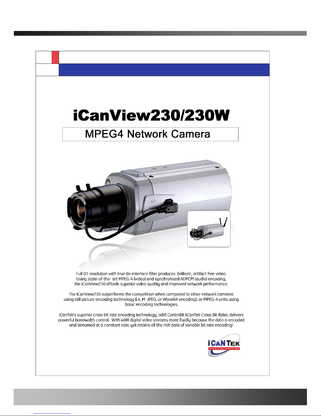
The iCanView230/230W is a state-of-the-art network camera which transmits synchronized video
and audio data in real time with D1 resolution at full frame rate. This is possible through MPEG4
CODEC technology, which provides high quality video with highly compressed data streams. The
iCanView230/230W can be connected, controlled and monitored from a remote location through an
IP connection over internet or intranet. Unlike CCTV or DVR, the iCanView230/230W is easy to
install and owner will experience cost and space savings in th e install ation ow ing to t he state of the
art technologies embedded in the system. Based on Embedded Software Solution (Embedded Web
Server, Embedded Streaming Server, Network Protocol), the iCanView230/230W ensures
unprecedented performance and stability to be an ideal network camera solution for system
integration solutions.
iCanView230/230W are offered with standard Ethernet interface while iCanView230/230W is
offered with embedded WiFi solution.
1.2. Features of iCanView230/230W
y 1 channel synchronized real time Video/Audio streaming
MPEG-4 video, ADPCM audio.
y Bi-directional audio communication
Real time audio communication between iCanView230/230W and Client PC
y The viewer assisted recording and playback functions.
y 1 Alarm sensor input/1 relay output
y Motion detection – Up to 3 motion detection zones
Arbitrary shape motion detection zone
Motion detection can initiate video recording, which is sent to the user through F TP and/or E-mail.
y Resolution
- NTSC : 704x480, 352x240, 176x144.
- PAL/SECAM : 704x576, 352x288, 176x144
y RS-485 interface for Pan/Tilt device connection
y Remote administration control
Entire operational parameter set up, Software upgrade
y Embedded WiFi interface (iCanVeiw230W only) – IEEE 802.11b/g
y Proprietary PoE (Power over Ethernet) for convenience of installation and cost savings
Rev.1.0 (Aug. 2006)
5 of 54

iCanView230/230W User’s Guide
1.3. Applications of iCanView230/230W
y Security surveillance (buildings, stores, manufacturing facilities, parkin g lots, banks, government
facilities, military, etc.)
y Real time Internet broadcasting
y Remote monitoring (hospitals, kindergartens, traffic, public areas, etc.)
y Teleconference (Bi-directional audio conference)
y Remote Learning
y Weather and environmental observation
Rev.1.0 (Aug. 2006)
6 of 54
iCanView230/230W User’s Guide
2. Product Description
2.1. Contents
Open the package and check if you have the followings:
Components Description Remarks
iCanView230/230W iCanView230/230W Network Camera
Power adapter
Input : 100~250V 50-60Hz
Output : +12V, 1.0A
Standard Power
AC power cable AC 250V, 10A~16A
Antenna iCanView230W only
CD-ROM Software & User’s Guide
Quick Reference Guide Quick installation guide Will be provided
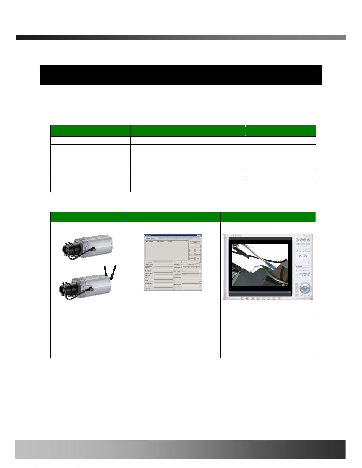
2.2. Preview
iCanView230/230W IP-Installer i-NVR
1CH MPEG-4 Network
Camera
PC software to allocate an IP
address to the
iCanView230/230W
PC software to view and record
the A/V streaming data
transmitted from
iCanView230/230W
2.3. Physical description
2.3.1. Front View
Rev.1.0 (Aug. 2006)
7 of 54
iCanView230/230W User’s Guide
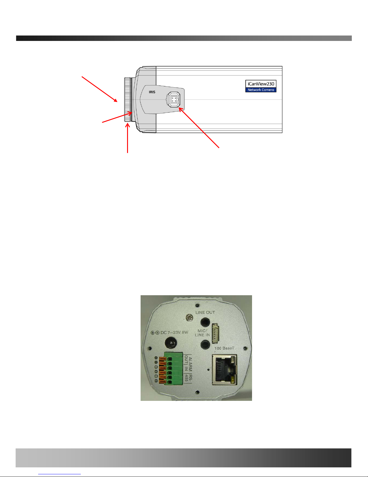
Figure 2-1. Side view of iCanView230/230W
y Lens : iCanView230/230W is basically delivered without Lens assembly. Standard C or CS
type lens can be accommodated into iCanView230/230W. Either DC Iris lens or Non-DC Iris lens
can be used with iCanView230/230W.
y Microphone : Picks-up sound from the environment for transmission over the network.
y CS Lens Mount Ring : Used for attaching lens unit to iCanView230/230W.
y Auto Iris Control : Plug in the cable from standard DC-Iris lens.
2.3.2. Rear panel
Lens
Microphone
CS Lens Mount ring
Auto Iris Control
Figure 2-2. Rear views of iCanView230/230W
Rev.1.0 (Aug. 2006)
8 of 54

iCanView230/230W User’s Guide
y MIC /LINE IN : Connect external audio source or microphone. If external audio is connected,
embedded microphone will be disabled.
Use Standard stereo earphone jack for the connection
Audio In
Ground
Not used
Audio In
Ground
Not used
Audio out
Ground
Not used
Audio out
Ground
Not used
Figure 2-3. Pin assignment of the plug for MIC/LINE In (left) and
LINE OUT (right)
y LINE OUT : Connect speakers with built in amplifier. Audio from remote site is output through
Line out in bi-directional audio mode.
Use Standard stereo earphone jack for the connection.
y 100BaseT : 100Mbps Ethernet connector (RJ-45) with proprietary PoE.
- LINK LED : Continuous yellow light means that network cable is plugged in. It will flicker
when there is traffic.
- Status LED: Green color indicates that the camera is in normal operation mode, while RED
color indicates that the camera is in abnormal condition.
y RS-232C & Video-out
3 Pins from the bottom of the connector are assigned for RS-232 port, while the remaining 2
pins are used for checking composite video output from the camera. Please note that the
bottom most pin is numbered as 1.
Pin Description Misc.
1 TxD of RS-232C For debugging & factory use only.
2 RxD of RS-232C For debugging & factory use only.
3 Ground of RS-232C For debugging & factory use only.
4 Video out from the camera For use in installation.
5 Ground for Video out. For use in installation
Rev.1.0 (Aug. 2006)
9 of 54

iCanView230/230W User’s Guide
y DC7-23V, 8W: Power input of iCanView230/230W.
Do not apply power through this power input when power is applied through LAN cable using
proprietary PoE.
y RS-485 and ALARM IN/OUT : Used for connecting P/T device, sensor, and alarm devices to
iCanView230/230W. Note that the bottom most pin is numbered as 1. Pin assignments are as
follows
Pin Description Misc.
1 RS-485 Negative (-)
2 RS-485 Plus (+)
3 Alarm In (-) NC/NO selectable in admin mode.
4 Alarm In (+) NC/NO selectable in admin mode.
5 Alarm Out
6 Alarm Out
Relay output : closed circuit in alarm
to indicate alarm status.
RS-485 : Used for connecting Pan/Tilt and Zoom devices having RS-485 interface
standard.
Alarm In : Connect external alarm sensors such as the infrared sensors, heat
sensor, magnetic sensors, etc. NC/NO selectable in the admin page.
Alarm Out : It is used for connecting external alarm generators such as sirens,
flashing light, etc. When activated, relay output configures a closed circuit.
Please refer to Section 6.1 for more detailed description on the Alarm In/Out
connections.
y Reset : Factory Default Switch
There is a switch provided for returning the network camera to factory default state. Press the
switch about 3 seconds through a tiny hole at the left of the 100BaseT connector using tools
with sharp tip for a few seconds while power is applied.
y Antenna Connector : Connector for connecting 3dBi antenna supplied with iCanView230W
Rev.1.0 (Aug. 2006)
10 of 54

iCanView230/230W User’s Guide
2.4. PC Requirements
AV streaming data received from iCanView230/230W can be decoded or stored in a PC running iNVR program which is a viewing & recording program for a PC. Minimum requirement of the PC is
described below:
Minimum Recommended
CPU Pentium III 700 Pentium IV 1.2G above
Main Memory 128 MB 256MB above
Operating system
*
Windows 2,000 or later Windows 2,000 or later
Web browser Internet Explorer 5.0 Internet Explorer 5.0 above
Resolution 1,024 X 768 Higher than 1,024 X 768
Network 10 Base-T Ethernet 100 Base-T Ethernet
* Operating Systems supported : Windows 2000 Professional
Windows XP Professional / Windows XP Home Edition
2.5 Quick Installation Guide
Brief information for rapid installation is provided in this section. For more detailed information you
are recommended to refer to pertinent documentations provided with the product or refer to
iCanTek’s home page (http://www.icantek.com)
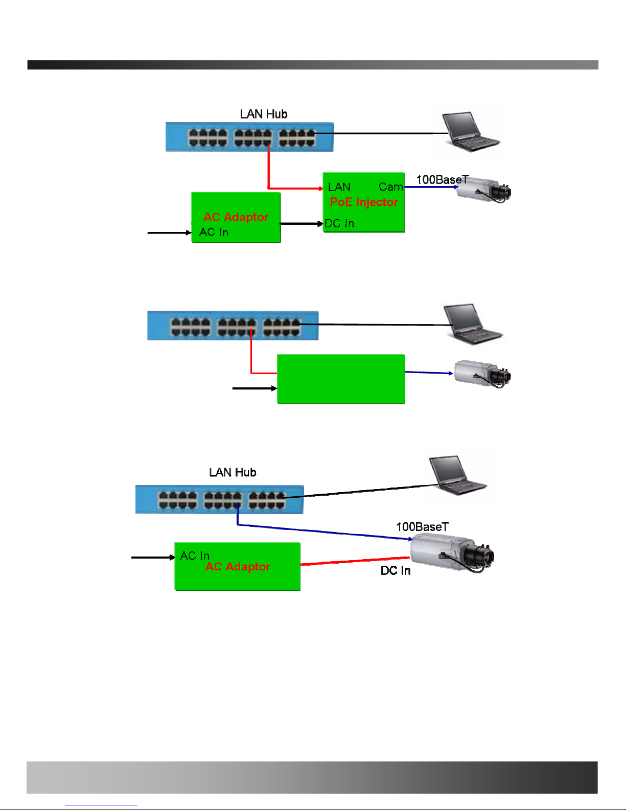
1. Connect iCanView230/230W to LAN by using one of the following method
1) If you have power adaptor and PoE injector, connect the network camera and PC as
illustrated in Figure 2.4. Both power and network connection is made with a single LAN
cable.
2) If you have power adaptor with PoE, connect the network camera and PC as illustrated in
Figure 2.5. Both power and network connection is made with a single LAN cable.
z The propriety PoE (Power over Ethernet) adds convenience in installing the network
camera by providing both power and LAN connection using single LAN cabling.
3) If you have standard power connect the network camera and PC as illustrated in Figure
2.6.
Rev.1.0 (Aug. 2006)
11 of 54
iCanView230/230W User’s Guide
Figure 2-4. Connecting Network camera and PC using PoE Inj ector
AC Adapt o r
with PoE
LAN Hub
LAN Cam
AC In
AC Adapt o r
with PoE
LAN Hub
LAN Cam
AC In
Figure 2-5. Connecting Network camera and PC using PoE Adaptor
Figure 2-6. Connecting Network camera and PC without using PoE
<Caution>
The products of iCantek does not support standard PoE. Do not connect the
network camera directly to a hub supporting standard PoE.
iCantek assumes no responsibility for the damages caused by use of standard PoE
device with iCanTek’s products.
Rev.1.0 (Aug. 2006)
12 of 54

iCanView230/230W User’s Guide
2. Apply power to iCanView230/230W
3. Install “IP installer” and “i-NVR” on your PC.
Detailed information for installing these programs can be found in [IP-Installer User’s
Guide] and [i-NVR User’s Guide], respectively.
4. Assign IP address to iCanView230/230W using IP installer.
Identify the type of the network environment and set up IP address. Detailed process of
setting up IP address can be found in [IP-Installer User’s Guide]. If network type is
xDSL or Cable modem you need supplementary information provided by your ISP.
5. Connect to iCanView230/230W in Administrator Mode for initial parameter set-up.
All parameters are set to factory default state when iCanView230/230W is delivered. You
are asked to configure the system for your environment in administration mode. Detailed
information of using administration mode can be found in [5. Configuring
iCanView230/230W in Administrative Mode]. Among the parameters, the parameters
in the following table should be set-up with proper values. Detailed information for the
parameters in Administrator Mode is found in [5. Configuring iCanView230/230W in
Administrative Mode]
[Note]: Set-up values are preserved even the power is turned off.
Page Parameter Setup value Factory default value
Video Size
Set the resolution of the video
transmitted from iCanView230/230W.
Max Upload Rate
Set this value smaller than the upload
speed of your network.
Frame Rate
The number of frames to be
transmitted per second.
Basic Setup
Video Rate
Bandwidth assigned for video
transmitted from iCanView230/230W.
Make sure that you press Check
button to find out the number of
maximum possible simultaneous
users then set the number of
users smaller than or equal to the
number.
User Admin
& Time
Setup
Administrator
name &
password
For safety, you are recommended to
change these values from factory
default. For new connection, you need
to input changed values for
corresponding fields. Do not disclose
Default value
Username : root
Password : dw2001
Rev.1.0 (Aug. 2006)
13 of 54

iCanView230/230W User’s Guide
these values to others and memorize
these values.
User Admin
& Time
Setup
Current Time
Input correct time in this field.
Default value :
2001/1/1
6. Connect the input and output signals to iCanView230/230W.
Connectors Function Signal description Number
LINE-
In/MIC
Audio in
Connect microphone or output from
audio devices.
1
Line Out
Audio out for
speaker
Audio from remote site is available
from this connector in bi-directional
audio mode. Connect speaker with
amplifier.
1
Alarm In
Connecting
Alarm Sensor
IR sensor, Motion Sensor, Smoke
Detector…
1
Alarm Out
Connecting
Alarm
annunciating
device
Siren, Flashing Light, … 1
RS485 PT device control
Remote P/T/Z device connection
having RS485 interface.
1
100Base-T
Network
connection
Connect iCanView230/230W to the
network, LAN, ADSL or Cable modem.
1
7. Remote video connection to iCanView230/230W
Run i-NVR on your PC. Before connecting to iCanView230/230W it is needed to configure
the connection information on the i-NVR. More det ailed inf ormation of usin g “i-NVR” can be
found in [i-NVR User’s Guide].
Rev.1.0 (Aug. 2006)
14 of 54
iCanView230/230W User’s Guide
3. Connecting iCanView230/230W to Network
iCanView230/230W supports LAN, xDSL, and Cable modem. It also supports shared IP
environment where single IP address is shared by at least 2 IP devices. Refer to [IP-Installer
User’s Guide] for details of setting the IP address for iCanView230/230W.
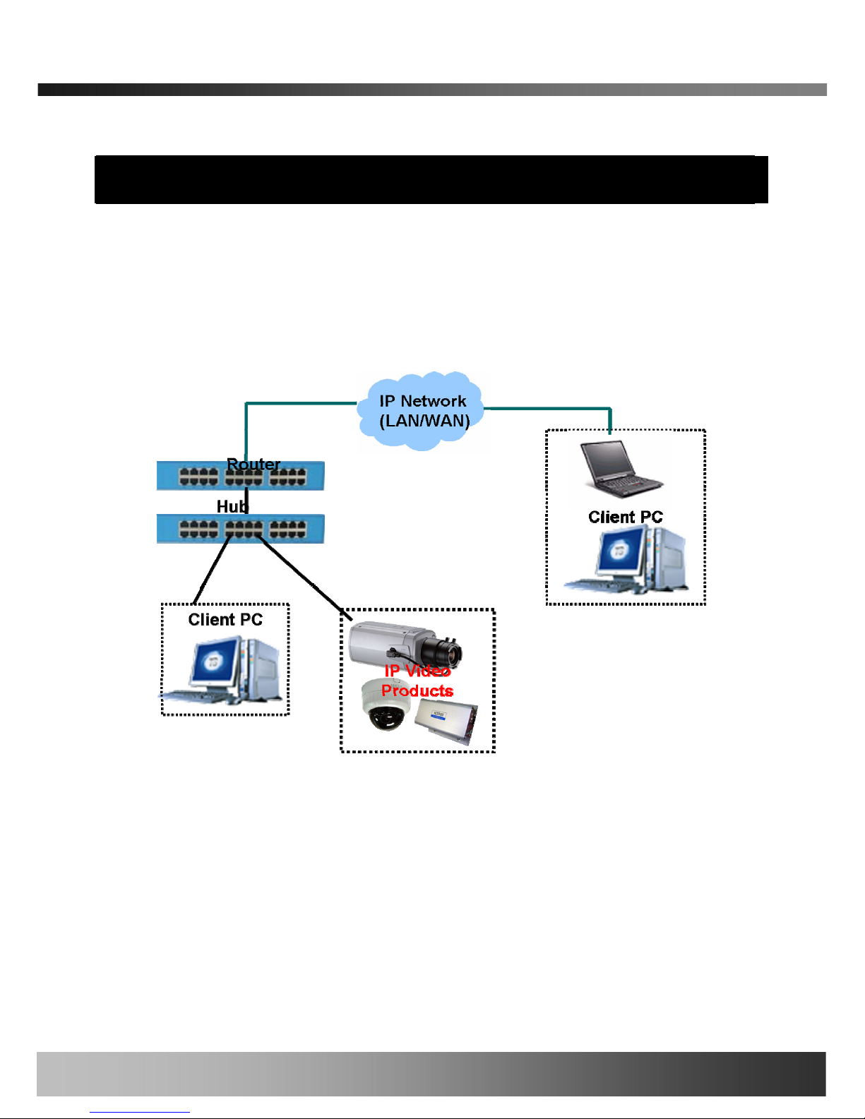
3.1. Connecting to LAN
In case of connecting the iCanView230/230W to LAN, it is generally connected as in Figure 3-1.
Figure 3-1. Connecting the iCanView230/230W to LAN
1. Follow through steps 1 to 4 in Section 2.5 to assign IP address to iCanView230/230W.
2. Install iCanView230/230W and connect it to desired LAN.
3. Check if you can receive video data when connecting to iCanView230/230W using the viewer
program.
4. When one or more IP video products are connected through a IP sharing device (i.e. router) to a
larger network (i.e. the internet), in order to access each unit from outside the local area network,
each device must have a unique RTSP (Real Time Stream Protocol) and HTTP port number. You
must also configure your IP sharing device for “port forwarding”. This is to enable the IP sharing
Rev.1.0 (Aug. 2006)
15 of 54
iCanView230/230W User’s Guide
device to forward packet data with unique port number (RTSP and HTTP) to unique internal IP
address (local IP address). If you only plan to access multiple units from within a local area
network, you do not need to change the RTSP and HTTP port numbers, unless other IP sharing
devices sit in-between the client and the IP video products. For more detailed information
regarding the use of IP sharing device refer to the document [Use of Private IP network using
IP-sharing-device].
②
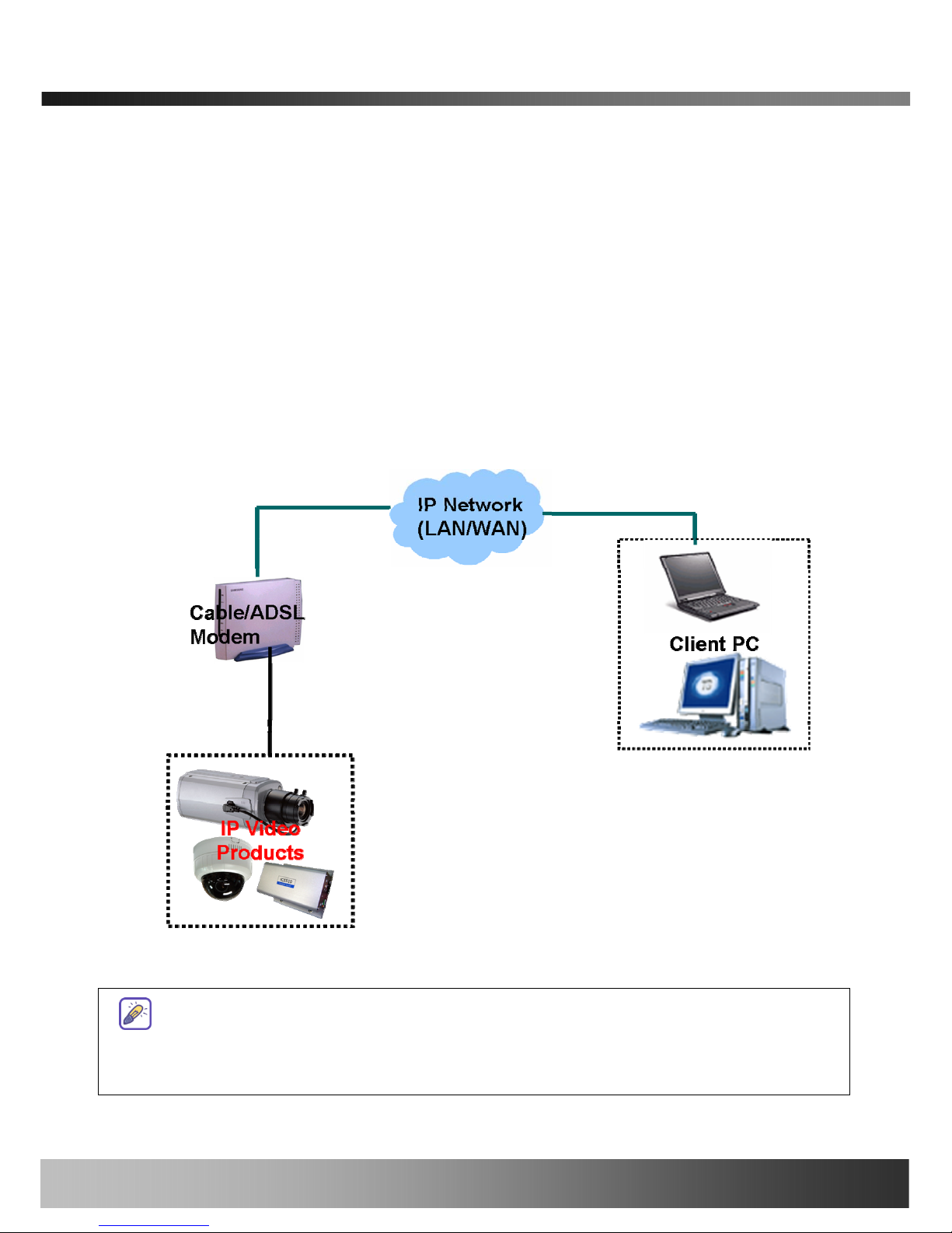
3.2. Connecting to xDSL/Cable Modem
1. Follow through steps 1 to 4 in Section 2.5 to assign IP address and other network parameters to
iCanView230/230W.
2. Install iCanView230/230W and connect it to xDSL or Cable modem as in Figure 3-2.
Figure 3-2. Connecting the iCanView230/230W to ADSL Modem
When fixed IP address is assigned to the xDSL or Cable modem, follow the same way as
assigning IP address for the case of LAN using IP-installer. To enable the notification of the
changed IP address to the user over e-mail when the IP address is changed in floating IP
Rev.1.0 (Aug. 2006)
16 of 54
iCanView230/230W User’s Guide
environment, you have to assign the e-mail address when user name and password are
input using IP-installer. (Management server provides a convenient way of
connecting to your network camera under dynamic IP environment. Please refer
to the Application note regarding “Management Server” in the CD.)
When connecting iCanView230/230W to xDSL or Cable modem, usually regular LAN
cable is required. But since some modems has crossover connections, please contact
your service provider for detailed information.
Rev.1.0 (Aug. 2006)
17 of 54
 Loading...