


iCanView110/110W User’s Guide
Rev1.4(Jan. 2005)

iCanView110/110W User’s Guide
Rev.1.4 (Jan. 2005)
2 of 56
Note
This equipment has been tested and found to comply with the limits for a Class A digital
device, pursuant to part 15 of the FCC Rules. These limits are designed to provide
reasonable protection against harmful interference in a residential installation. This
equipment generates, uses and can radiate radio frequency energy and, if not installed
and used in accordance with the instructions, may cause harmful interference to radio
communications. However, there is no guarantee that interference will not occur in a
particular installation. If this equipment does cause harmful interference to radio or
television reception, which can be determined by turning the equipment off and on, the
user is encouraged to try to correct the interference by one or more of the following
measures :
z Reorient or relocate the receiving antenna.
z Increase the separation between the equipment and receiver.
z Connect the equipment into and outlet on a circuit different from that to which
the receiver is connected
z Consult the dealer or an experienced radio/TV technician for help.
Directions
iCanView110 is designed for indoor use only. When using iCanView110 outdoors or in n
environment that exceeds the limited range, you must separately use a water-resistant case.
Be careful not to cause any physical damage by dropping or throwing the iCanView110 A/V Server.
Especially keep the A/V server out of reach from children.
Do not disassemble iCanView110. You will be excluded from After Service when disassembled.
Use only the power adapter provided with the iCanView110.
If you would like to use the iCanVie w110 A /V se rver for security, monitoring, please check the legal
regulations within the country.

iCanView110/110W User’s Guide
Rev.1.4 (Jan. 2005)
3 of 56
Revision History
Date Rev No Description
2004-7 1.1
2004-12-29 1.3 Supporting PC - Removed Window 98SE
Modifications and new features in Admin page
Network, Motion detection, Encryption, Upgrade
2005-2-21 1.3.8 Removed periodic ftp transfer.
Caution
Any changes or modifications in construction of this device which are not expressly
approved by the party responsible for compliance could void the user’s authority to
operate the equipment.
This appliance and its antenna must not be co-located or operating in conjunction with
any other antenna or transmitter. A minimum separation distance of 20 cm must be
maintained between the antenna and the person for this appliance to satisfy the RF
exposure requirements.

iCanView110/110W User’s Guide
Rev.1.4 (Jan. 2005)
4 of 56
1. Introduction............................................................................................................................................5
1.1. Overview..........................................................................................................................5
1.2. Features of iCanView110............................................................................................... 5
1.3. Applications of iCanView110.........................................................................................5
2. Product Description ...............................................................................................................................7
2.1. Contents .......................................................................................................................... 7
2.2. Preview ............................................................................................................................ 7
2.3. Physical description........................................................................................................ 8
2.5 Quick Installation Guide................................................................................................ 12
3. Connecting the iCanView110..............................................................................................................15
3.1. Connecting to LAN ........................................................................................................15
3.2. Connecting to xDSL Modem........................................................................................16
3.3. Connecting to Cable Modem.......................................................................................17
4. IP-Installer............................................................................................................................................20
4.1. Main window of IP-Installer ........................................................................................ 20
5. Configuring the A/V Server in Administrative Mode ........................................................................21
5.1. Log On............................................................................................................................21
5.2. Basic Setup.................................................................................................................... 23
5.3. Network Configuration.................................................................................................25
5.4. Wireless Configuration.................................................................................................28
5.5. CCD Adjustment...........................................................................................................30
5.6. User Admin & Time Setup...........................................................................................33
5.7. Sensor & Capture Setup.............................................................................................. 36
5.8. Alarm Device Setup...................................................................................................... 38
5.9. Motion Region Setup.................................................................................................... 39
5.10. PTZ Setup....................................................................................................................41
5.11. Encryption Set up.......................................................................................................43
5.12. Upgrade & Reset.........................................................................................................45
5.13. Status Report.............................................................................................................. 47
6. Tips for Using iCanView110................................................................................................................48
6.1. ALARM-IN and ALARM-OUT.........................................................................................48
6.2. Trouble Shooting...........................................................................................................51
6.3. Web Viewer.................................................................................................................... 53
6.4. How To Upgrade Your iCanView110 System.............................................................55
Table of Contents

iCanView110/110W User’s Guide
Rev.1.4 (Jan. 2005)
5 of 56
1. Introduction
1.1. Overview
The iCanView110 is a state-of-the-art network camera (and simultaneously a 1-channel A/V server)
which transmits both video and audio data in real time with high-resolution at high frame rate. This
is possible through MPEG4 CODEC technology, which provides data transmission at high
compression rates with high data resolution via networks. The iCanView110 can be connected,
controlled and monitored from a remote location through an IP address. Un like CCTV or DVR, the
iCanView110 is easy to install and also cuts costs and space without any additi onal installati on.
Based on Embedded Software Solution (Embedded Web Server, Embedded Streaming Server,
Network Protocol), the iCanView110 ensures high performance and stability and provides
integration of various Internet solutions.
iCanView110 is a model having Ethernet interface while iCanView110W is a model having
embedded WiFi interface.
1.2. Features of iCanView110
y 1 channel real time Video/Audio streaming based on MPEG-4 video and ADPCM audio.
y 1 channel Bidirectional Audio between iCanView110 and Client PC for two-way communication
y The viewer assists recording and playback functions.
y 1 Alarm sensor input/1 relay output
y Motion detection – Up to 3 motion detection regions.
Motion detection can initiate video recording, which is sent to the user through FTP and/or E-mail.
y Resolution : - NTSC Video - PAL/SECAM : support
640x480(for still image/small motion)/640x240 for 1 channel, 320x240/176x144 for 4 channels.
704x576(for still image/small motion)/704x288 for 1 channel, 352x288/176x144 for 4 channels
y Remote P/T/Z control
y Remote software upgrade over Network
y Ease of use and convenient user interface.
y Embedded WiFi interface (iCanVeiw110W only) – IEEE 802.11b
1.3. Applications of iCanView110
y Security surveillance (buildings, stores, factories, parking lots, banks, government facilities,
military, etc.)

iCanView110/110W User’s Guide
Rev.1.4 (Jan. 2005)
6 of 56
y Real time Internet broadcasting (resort areas, events, etc.)
y Remote monitoring (hospitals, kindergartens, traffic, public areas, etc.)
y Teleconference (Bi-directional audio conference)
y Remote Learning
y Weather and environmental observation
iCanView110/110W User’s Guide
Rev.1.4 (Jan. 2005)
7 of 56
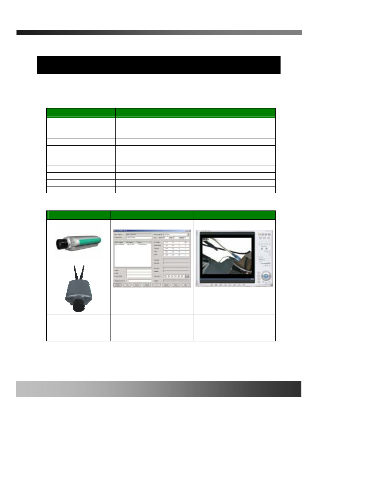
2. Product Description
2.1. Contents
Open the package and check if you have the followings:
Components Description Remarks
iCanView110(W) iCanView110 Network Camera/Server
Power adapter
Input : 100~250V 50-60Hz
Output : +12V, 1.0A
AC power cable AC 250V, 10A~16A
LAN cable 2m LAN cable – Crossover type
For direct connection
between the server and
PC.
Antenna 3 dBi Omni-antenna iCanView110W only
CD-ROM Software & User’s Guide
Quick Reference Guide Quick installation guide Will be provided
Warranty Will be provided
2.2. Preview
iCanView110/110W IP-Installer i-NVR
1CH MPEG-4 Network
Camera/Server
PC software to allocate an IP
address to the iCanView110
PC software to view and record
the A/V streaming data
transmitted from iCanView110
iCanView110/110W User’s Guide
Rev.1.4 (Jan. 2005)
8 of 56
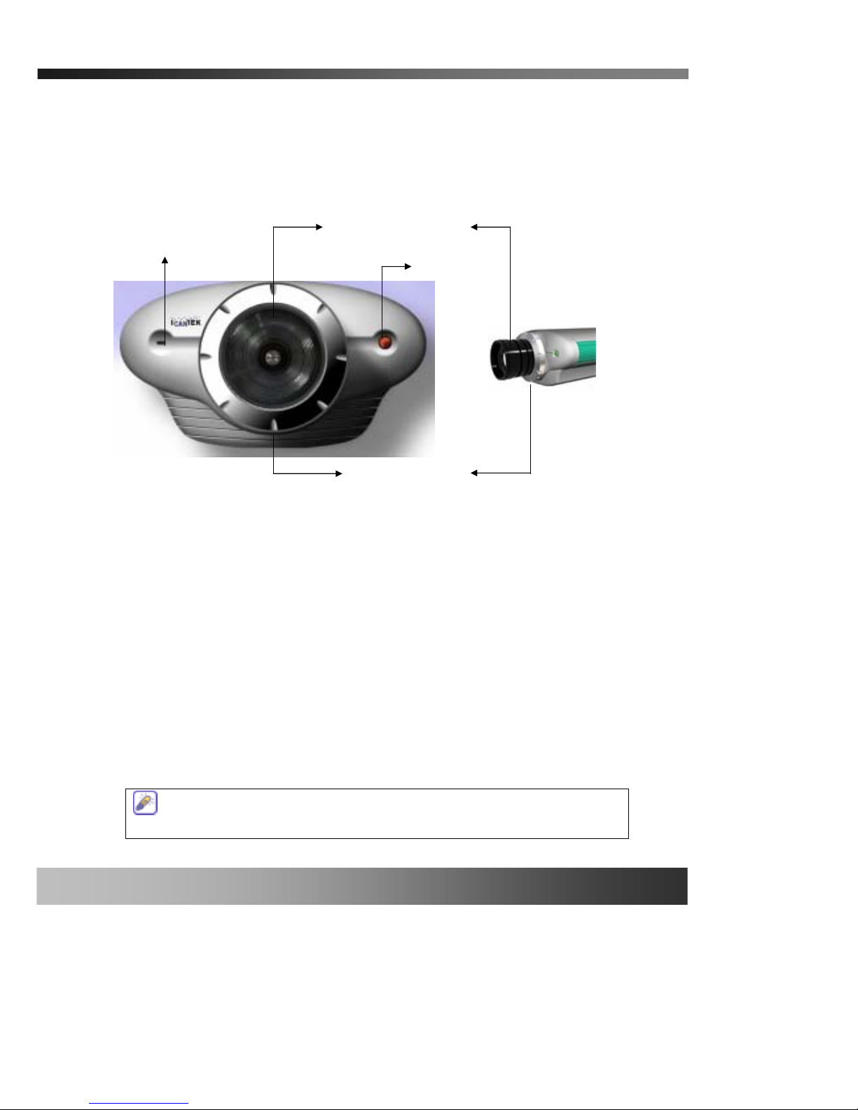
2.3. Physical description
2.3.1. Front View
Figure 2-1. Front view of iCanView110
y Lens Assembly : It is a fixed focus lens with CS type mounting fixture. It can be replaced
with other types with C/CS mounted fixed focus lens or DC IRIS lens.
y Status Indicator LED : Status indicator LED shows the status of iCanView110 in 3 different
colors.
1 Green : Green color indicates that iCanView110 is in normal operating condition.
Continuous green light indicate s that iCanView110 is ready for transmitting data.
Flickering green light means that someone is connected to iCanView110.
2 Red : Red light flickers or stays continuously on when the hardware of iCanView110 is in
abnormal condition.
3 Orange : Orange light flickers or stays continuously on when software of iCanView110 is
in abnormal condition.
Status Indicator LED
Fixed Focus Lenz
Microphone
CS Lens Mount ring
Status indicator LED temporarily lights red then returns to green when applying
power to iCanView110, which is normal condition.
iCanView110/110W User’s Guide
Rev.1.4 (Jan. 2005)
9 of 56
y Microphone : Picks-up sound from the environment for transmission over the network..
y Mount Ring : Used for attaching lens unit to iCanView110.
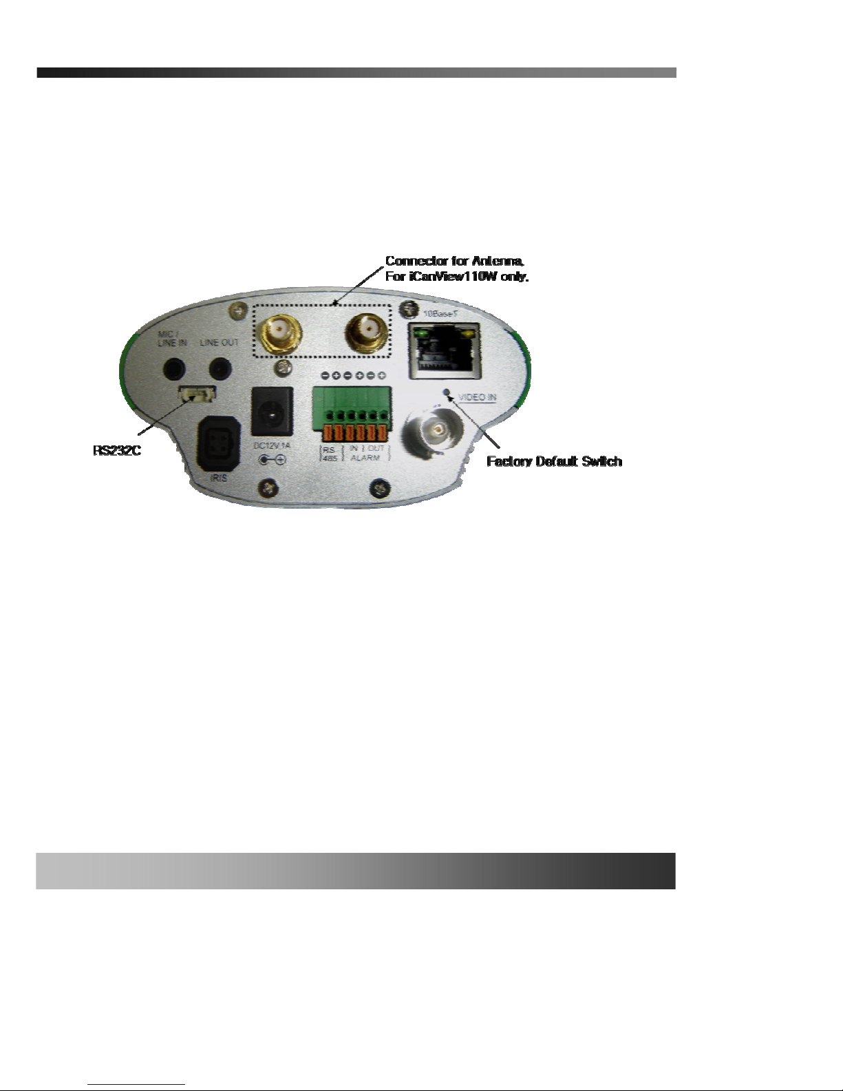
2.3.2. Rear panel
Figure 2-2. Rear Panel of iCanView110/110W
y MIC /LINE IN : It is used to connect external audio s o urce or mic rophone to iCanView110. If
external audio is connected, em be dd e d m icr ophone will be disabled.
y LINE OUT : It is used for connecting external speakers with built in amplifier. Audio from
remote site is output through Line out in bi-directional aud io mode.
Use Standard stereo earphone jack for the connection.
y 10Base-T : 10Mbps Ethernet connector (RJ-45).
y LINK LED : Green light means that network cable is in normal condition.
y LAN LED: When there is traffic on the LAN, yellow light flickers.

iCanView110/110W User’s Gui de
Rev.1.4 (Jan. 2005)
10 of 56
y RS-232C (3 pins) : Used only by developers for development and production. Not for use by
end users.
y DC12V, 1A: Power input of iCanView110. 12V/1A
y DC-IRIS : Plug in the cable attached on standard DC-Iris lens.
y RS-485 and ALARM IN/OUT : Is is used for connecting P/T/Z and alarm devices to
iCanView110. Pin assignments are :
Pin 1 RS-485 Negative (-) input
Pin 2 RS-485 Plus (+) input
Pin 3 Alarm In (-)
Pin 4 Alarm In (+)
Pin 5 Alarm Out (-)
Pin 6 Alarm Out (+)
RS-485 : Used for connecting Pan/Tilt and Zoom devices having RS-485 interface
standard.
Alarm In : It is used for connecting external alarm sensors such as the infrared
sensors, heat sensor, magnetic sensors, etc.
Alarm Output : It is used for connecting external alarm generators such as sirens,
flashing light, etc. When acti vated, relay output configures a closed circuit
y VIDEO-IN : Video input for video device(DVD, TV and etc) (composite NTSC, PAL, SECAM)
y Factory Default Switch : There is a switch provided for returning the network camera to
factory default state. Press the switch through a tiny hole above the Video-In connector using
sharp tool for a few seconds while power is applied.
y Antenna Connector : Connector for connecting 3dBi antenna supplied with iCanView110W
Refer to detailed information of Alarm in/Out to 6.1. ALARM-IN and ALARM-OUT in this guide

iCanView110/110W User’s Gui de
Rev.1.4 (Jan. 2005)
11 of 56

iCanView110/110W User’s Gui de
Rev.1.4 (Jan. 2005)
12 of 56
2.4. PC Requirements
AV streaming data from iCanView110 can be observed through i-NVR program which is a viewing &
recording program running on a PC. Minimum requirement of the PC is described below:
Minimum Recommended
CPU Pentium III 700 Pentium IV 1.2G above
Main Memory 128 MB 256MB above
Operating system* Windows 2000 or later Windows 2000 or later
Web browser Internet Explorer 5.0 Internet Explorer 5.0 above
Resolution 1,024 X 768 Higher than 1,024 X 768
Network 10 Base-T Ethernet 10/100 Base-T Ethernet
* Operating Systems supported : Windows 2000 Professional
Windows XP Professional / Windows XP Home Edition
2.5 Quick Installation Guide
Brief information for rapid installation is provided in this section. For more detailed information you
are recommended to refer to pertinent documentations provided with the product or refer to
iCanTek’s home page (http://www.icantek.com)
1. Connect iCanView110 to your PC or network by using one of the following method
i. Connect your PC and iCanView110 using the Cross Type LAN cable provided with
iCanView110 or
ii. Connect iCanView110 and PC to same LAN using Direct Type cable.
2. Apply power to iCanView110
3. Install “IP installer” and “i-NVR” on your PC.
Detailed information for installing these programs can be found in [IP-Installer User’s
Guide] and [i-NVR User’s Guide] in this CD, respectively.
4. Assign IP address to iCanView110 using IP installer.
Identify the type of the network e nvironment and set up IP address. Detailed process of
setting up IP address can be found in [IP-Installer User’s Guide]. If network type is
xDSL or Cable modem you need supplementary information provided by your ISP .

iCanView110/110W User’s Gui de
Rev.1.4 (Jan. 2005)
13 of 56
5. Connect to iCanView110 in Administrator Mode for initial parameter set-up.
All parameters are set to factory default state when iCanView110 is delivered to you. You
are asked to configure the system for your environ ment in administration mode. Detailed
information of using admi ni st ration mode can be found in [5. Configuring the A/V Server
in Administrative Mode]. Among the parameters, the parameters in the following table
should be set-up in proper values. Detailed information for the parameters in Administrator
Mode is found in [5. Configuring the A/V Server in Administrative Mode]
[Note]: Set-up values are preserved even the power is turned off.
Page Parameter Setup value Factory default value
Video Size
Define the resolution of the video
transmission from iCanView110.
Max Upload Rate
Set this value smaller than the upload
speed of your network.
Frame Rate
It indicates the number of frames to
be transmitted per second.
Basic Setup
Video Rate
It indicates the bandwidth allowed for
video transmitted from iCanView110.
Make sure that you press Check
button to find out the number of
maximum possible simultaneous
users then set the number of
users smaller than or equal to the
number.
User Admin
& Time
Setup
Administrator
name &
password
For safety, you are recommended to
change these values from factory
default. For new connection, you need
to input changed values for
corresponding fields. Do not expose
these values to others and memorize
these values.
Default value
Username : root
Password : dw2001
User Admin
& Time
Setup
Current Time
Input correct time in this field.
Default value :
2001/1/1
6. Connect the inputs and output signals to iCanView110.
iCanView110 does not function properly if there is no video and audio input.
Refer to the following table. You have to connect at least one Video In.
Connectors Function Signal description Number
Video In Input video Analog video outputs from analog 1

iCanView110/110W User’s Gui de
Rev.1.4 (Jan. 2005)
14 of 56
connector CCTV camera, DVD, TV etc.,
(NTSC/PAL/SECAM)
LINE-
In/MIC
Audio in
Connect microphone or output from
audio devices.
1
Line Out
Audio out for
speaker
When in bi-directional audio mode,
Audio signal from remote site is
available from this connector. Use
speaker with amplifier.
1
Alarm In
Connecting
Alarm Sensor
IR sensor, Motion Sensor, Smoke
Detector…
2
Alarm Out
Connecting
Alarm alerting
device
Siren, Flashing Light, … 2
RS485
PTZ device
control
Remote P/T/Z control having RS485
interface.
1
10Base-T
Network
connection
Connect iCanView110 to Ethernet
connector from Hub, PC, ADSL or
Cable modem.
1
5. Remote video connection to iCanView110
You can connect to iCanView110 in video mode by running “i-NVR” program on your PC. Detailed
information of using “i-NVR” can be found in [i-NV R User’s Guide].
iCanView110/110W User’s Gui de
Rev.1.4 (Jan. 2005)
15 of 56
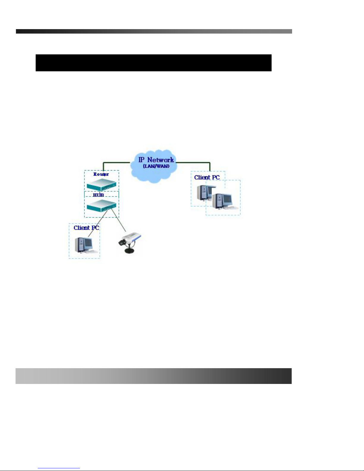
3. Connecting the iCanView110
iCanView110 supports LAN, xDSL, and Cable modem. It also support shared IP network where
single IP is shared by many devices using IP sharing device. Refer to [IP-Installer User’s
Guide] for details of setting the IP address for the iCanView110 by using the “IP-Installer”.
3.1. Connecting to LAN
In case of connecting the iCanView110 to LAN, it is generally connected as follows{Figure 3-
1.}
Figure 3-1. Connecting the iCanView110 to LAN
1. After applying the power, connect the LAN cable and assign an IP address to iCanView110 by
using the IP-Installer.
2. To assign an IP address to the iCanView110, run the IP-Installer in the PC connected in the same
subnet as iCanView110 is connected.
3. Check if you can receive video data when connecting to iCanView110 using the viewer program.
②
iCanView110/110W User’s Gui de
Rev.1.4 (Jan. 2005)
16 of 56
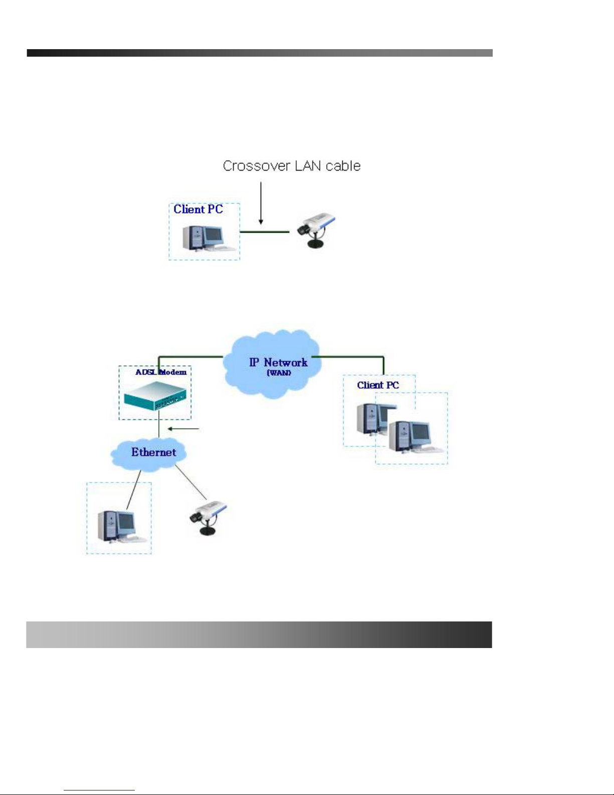
3.2. Connecting to xDSL Modem
1. Apply power and connect the PC and iCanView110 using crossover LAN cable provided with
the system.
2. Setup network parameters by running “IP-Installer.”
Figure 3-2. Direct connection using crossover LAN cable
Figure 3-3. Connecting the iCanView110 to ADSL Modem

iCanView110/110W User’s Gui de
Rev.1.4 (Jan. 2005)
17 of 56
3. Remove the crossover LAN cable and connect the iCanView110 to the network using
regular LAN cable. Check if you can receive video data when connecting to iCanView110 using
the viewer program.
3.3. Connecting to Cable Modem
1. Apply power and connect the PC and iCanView110 using crossover cable provided with the
system.
2. Setup network parameters by running “IP-Installer”. {Refer to Figure 3-4}.
When connecting iCanView110 to xDSL Modem, usually regular LAN cable is
required. But since some xDSL Modems has crossover connections, please
contact your xDSL provider for detailed information.
When fixed IP address is assigned to the xDSL, follow the same way as assigning IP
address for the case of LAN using IP-installer. To enable the notification of the
changed IP address to the user over e-mail when the IP address is changed in
floating IP environment, you have to assign the e-mail address when user name and
password are input using IP-installer. (Management server provides a
convenient way of connecting to your network camera under dynamic IP
environment. Please refer to the Application note regarding “Management
Server” in the CD.)

iCanView110/110W User’s Gui de
Rev.1.4 (Jan. 2005)
18 of 56
Figure 3-4. Direct connection using crossover LAN
3. Remove the crossover cable and connect the iCanView110 to the network using regular LAN
cable as shown in Figure 3-5. Check if you can receive video data when connecting to
iCanView110 using the viewer program.
Figure 3-5. Connecting the iCanView110 to Cable Modem

iCanView110/110W User’s Gui de
Rev.1.4 (Jan. 2005)
19 of 56
When connecting the iCanView110 to cable modem, usually regular LAN cab le is required. But
since some cable modems has crossover connections, please contact your cable modem service
provider for detailed information.
When fixed IP address is assigned to the Cable Modem, follow the same way as
assigning IP address for the case of LAN using IP-installer. To enable the notification
of the changed IP address to the user over e-mail when the IP address is changed in
floating IP environment, you have to assign the e-mail address when user name and
password are input using IP-installer. (Management server provides a
convenient way of connecting to your network camera under dynamic IP
environment. Please refer to the Application note regarding “Management
Server” in the CD.)

iCanView110/110W User’s Gui de
Rev.1.4 (Jan. 2005)
20 of 56
4. IP-Installer
iCanView110 needs an IP address for connection to the network(Internet/Intranet). IP-Installer is a
PC program developed to assign an IP address and setup network parameters to digital video
security network products such as Netw ork Camera and A/V Se rver. IP-Installer is provided in a CD
supplied with iCanView110 or it can be downloaded from “www.icantek.com
”.
Detailed information of Installing and running IP-installer can be found in [IP-installer
user’s guide]
4.1. Main window of IP-Installer
Figure 4-1. IP-Installer
①
②
③
④
⑤
⑥
⑦
⑧
⑨
⑩
⑪
⑫
⑬
⑭ ⑮
○
16
○
17
○
18
○
19
○
20
○
21
○
22
○
23
○
24

iCanView110/110W User’s Gui de
Rev.1.4 (Jan. 2005)
21 of 56
5. Configuring the A/V Server in Administrative Mode
5.1. Log On
There are 2 ways of connecting to iCanView110 administrative mode. One is through standard
internet browser(Internet Explorer) and the other is through “ i-NVR” program.
1. Using Internet Explorer
You can log on to the server by clicking admin mode button or from your internet browser.
Type in as the followings in the address window of the Internet Explorer.
http://[iCanView110 IP address]/admin.htm
Example: http://172.16.64.1
33/admin.htm
If you changed the HTTP port from default value you can login by typing in:
http://[iCanView110 IP address]:[port]/admin.htm
Example: http://172.16.64.1
33:8080/admin.htm
2. Log on from “i-NVR”
Select video channel in the viewing window of “i-NVR”. Selected video channel will be
highlighted. Click
button on the right side of the display screen.
Figure 5-1. Select display channel and click “Camera Admin” button for Log on to
administrative mode from “i-NVR”
3. Input User Name and Password in the display screen shown in Figure 5-2.
삭제됨: 7
삭제됨: 7

iCanView110/110W User’s Gui de
Rev.1.4 (Jan. 2005)
22 of 56
Figure 5-2. Log On Screen
Factory default User Name and Password are set as ‘root’ and ‘dw2001’, respectively. Click on “OK”
button to enter into the Basic Setup page of Admin Mode. If you have changed the username and
password of the Administrator, you must log on with the changed username and password.

iCanView110/110W User’s Gui de
Rev.1.4 (Jan. 2005)
23 of 56
5.2. Basic Setup
Setup the basic parameters of the iCanView110.
y Language Selection: You can select a language in the admin page.
- Supported languages : English, Korean, Japanese, Chinese, Spanish
y System Name
It is the name of the iCanView110. It is same as the one set-up by IP-installer. You can
reassign the system name in admin mode.
y Audio Input Selection
- Select the type of input audio for each channel. Line In is used for connecting audio
output from audio devices. Mic is used for connecting the output of microphone.
- Input Gain : Set the gain of the input audio.
y Video Quality & Bandwidth Control
- Input Video : Select the analog video standard for input. Select one from NTSC, PAL, SECAM.
Figure 5-3. Basic Setup

iCanView110/110W User’s Gui de
Rev.1.4 (Jan. 2005)
24 of 56
- Video Size : Select a video size for transmission. Allowed video size is different for each video
standard.
- NTSC(30 frames/sec Max.) : 176x144 / 320x240 / 640x240 / 640x480.
- PAL/SECAM (25 frames/sec Max.) : 176x144 / 352x288 / 704x288 / 704x576
z Max upload rate
Assign maximum bandwidth of the uplink for the network connected to iCanView110.
z Frame rate
Assign number of video frames transmitted for each second. You can improve picture
quality by lowering frame ra t e for the same bandwidth.
z Video rate
Assign bandwidth for tra nsm itting video data.
z Audio rate
Assign bandwidth for transmitting audio data. Audio data is not transmitted if you
select “NA”
y Check
After you finish set up of video and audio for all the channels, check this box to obtain the
possible maximum number of users (Possible Max Users) and remaining network bandwidth
(Remained) remaining when possible maximum users are connected.
y Possible Max Users
It shows the number of maximum simultaneous connections for the network connection set-up.
y Remained
It shows the network bandwidth remaining when Possible Max Users are connected.
.
y Limited users
Useful network bandwidth varies according to the condition of the network. This parameter is
used to limit the number of the simultaneous connections below the number shown in Possible
Max Users.
y Save
Save the set-up parameters when the set-up parameters are done.

iCanView110/110W User’s Gui de
Rev.1.4 (Jan. 2005)
25 of 56
5.3. Network Configuration
Setup the network parameters appropriately in accordance with your network environment. Many
of the parameters in this page is same as those used setup by “IP-Installer”.
y IP Assign Type : The network types supported by the iCanView110 are LAN(fixed IP), PPPoE,
and DHCP(automatic IP allocation)
Figure 5-4. Network Configuration

iCanView110/110W User’s Gui de
Rev.1.4 (Jan. 2005)
26 of 56
- When the network environment is fixed IP, select ‘LAN’ in the network type, and put the IP
address, Subnet Mask, Gateway, D NS1 and DNS2 ass igned by the network administrator or
ISP. DNS2 is used when DNS1 does not work.
- When the network environment is PPPoE and IP address is assigned automatically, select
‘PPPoE’ in the network type. Next, fill in the ‘User Name’ and ‘Password’ fi elds with the values
assigned by the network service provider.
- When the network environment is “automatic IP allocation by DHCP”, select ‘DHCP’ in the
network type.
y Refer to [IP-installer user’s guide] for “Clone MAC”.
y Refer to [IP-installer user’s guide] for “Host name and domain for Cable Modem”.
y Port Change : You can change the HTTP port, FTP port and RTSP port numbers. The RTSP port is
used to connect the “Viewer“ to the iCanServer410.
Each port should have a number below # 65535.
- HTTP : default “80”
- RTSP : default “554”
y IP Filtering : You can restrict the access to the administrator page from IP addresses beyond
certain IP address range.
- Restrict Administrator Access : Check this box to restrict administrative log on.
. Base IP Address : Input IP address of the PC which is intended to be used for log on to
administrative mode.
. Mask : This is same as subnet mask. It is used to allow administrative log on only to the
PCs located in the same subnet as the base IP address. If you want to allow only
one PC to access in administrative mode, set this value to 255.255.255.255.
- Recv E-Mail Address : Enter E-mail address to receive information sent from your network
camera. This is same as E-mail field in IP-installer.
- Return E-Mail Address : Fill in this field with correct e-mail address to identify the mail sent
from the network camera. If you are using web mail services having no SMTP server,
check the radio button at the left of “U sing Built-in SMTP Server” and enter valid e-mail
address to avoid spam filtering by the receiving e-mail server.
- Notify for IP Changed : If you check this, the IP address will be sent via E-mail whenever

iCanView110/110W User’s Gui de
Rev.1.4 (Jan. 2005)
27 of 56
the IP address changes. It is sent to the E-mail address set by
“Recv E-Mail Address”.
y FTP Server Setup : Setup IP address, Username, Password and Directory of FTP server to send
data in case of alarm. Default FTP port number is 21.
y Management Server : You can register the network camera to the Management Server for
various support including name service for your network camera.
- Log on to server : Check this box to enable log on to the Management Server. By log on to
the management server your network camera can use domain name instead of number
based IP address. This feature is particularly useful when your video server is using
dynamic IP address. Input valid Management Server name for the service.
You must open an account on the management server and register your network camera
under your account to use this feature. Domain name of your network camera can be
assigned when you register your video server to the management server under your
account.
One of the server available is mgmt.net-video.net. For the opening of an account visit
www.net-video.net
.

iCanView110/110W User’s Gui de
Rev.1.4 (Jan. 2005)
28 of 56
5.4. Wireless Configuration
For the case of a network camera having built in wireless LAN it is needed to set up wireless LAN
configuration parameters. Click “Wireless Configuration”.
Figure 5-5 Wireless Configuration
y Wireless LAN Setup
Set up parameters for wireless LAN.
- Use Wireless LAN : Select “Enable” to use wireless in terface. If “Disable” is selected,
Ethernet interface is used instead of wireless LAN interface.
- SSID : Enter the ID of the wireless LAN access point to be connected, when wireless LAN
interface is selected.
- Use WEP : Select the mode of WEP. If WEP is not used select “Disable”
- Key Value : Set the value of WEP Key.
- Wireless Power : Set the maximum transmission power level of Wireless LAN.
y WLAN Information
Information regarding wireless LAN interface is displayed.
- MAC Address : Indicates MAC address of the Wireless LAN card.

iCanView110/110W User’s Gui de
Rev.1.4 (Jan. 2005)
29 of 56
- BSSID : Indicates the ID of the connected Access Point. In general the MAC address of
the Access Point is shown.
- Current Channel : Indicates the channel number of present connection.
- Signal Strength : Indicates the strength of the received signal.
- Link Quality : Indicates the quality of the Link level.
- Tx Rate : Indicates the speed of the latest transmission.

iCanView110/110W User’s Gui de
Rev.1.4 (Jan. 2005)
30 of 56
5.5. CCD Adjustment
You can optimize the quality of input video by adjusting the parameter of CCD. To enter into this
mode, click “CCD Adjustment” in administrative page. You will find a screen shown in Figure 5-6.
Click “SAVE” to save the parameter after you finish the parameter setting.
Figure 5-6. CCD Adjustment
y CCD Type
Either NTSC or PAL type CCD sensor is installed in iCanView110. Type of CCD is identified
by the system and shown in this field.
y Lens Selection
Any lens having CS mount type can be installed on iCanView110. Stand ard iCanView110 is
delivered with C mount type fixed lens. In order for the convenience of replacement with CS
type, a C-CS adaptor is packaged with iCanView110.
Confirm whether your lens is Non DC IRIS or DC IRIS lens before your selection and then
click “SAVE” to save your selection.

iCanView110/110W User’s Gui de
Rev.1.4 (Jan. 2005)
31 of 56
y Exposure Control
Users of iCanView110 can select either Auto or Manual exposure control. Sub menus in Aut o
exposure mode are Backlight compensation and Flickerless enable.
Sub menus in Manual exposure are Shutter Speed and Gain Adjustment.
set parameters to control the amount of light reaching CCD sensor to obtain various video
Auto
Adjust the amount of light reaching CCD automatically. If this mode is
selected Backlight compensation and Flickerless enable submenus are
activated. To apply the sub menu check the box at the left of each sub
menu and click “SAVE”.
□ Backlight Compensation
When the camera is acquiring video from object with bright backlight, it
is hard to identify the details of targeting object since the object appears
very dark. Apply backlight compensation mode for this case. Default
mode is backlight compensation Off.
□ Flickerless Enable
In case of using NTSC type iCanViewV110 in 50Hz AC regions or using
PAL type iCanView110 in 60Hz AC region, video output tends to flicker
when iCanView110 is used under fluorescent lamps. This mode reduces
the flickering phenomena. If this mode is selected, electronic shutter
speed is set to 1/100 sec for NTSC camera while it is set to 1/120 for PAL
camera to synchronize the shutter speed to AC current.
<Note> : Make sure that you apply this mode only when using NTSC
camera in PAL region or PAL camera in NTSC region.
Manual Adjust the amount of light reaching CCD manually. Shutter speed and Gain
DC IRIS Lens
DC IRIS lens is a kind of auto IRIS lens. Opening of IRIS can be
adjusted by applying DC voltage. The opening of IRIS is optimally
adjusted by detecting the signal level from CCD. This type is
selected when CS Type DC IRIS lens is mounted on your
iCanView110.
Non DC IRIS
Lens
Non DC IRIS lens is a fixed IRIS lens. This is a standard lens that is
installed with iCanView110 unless requested otherwise. Non DC
IRIS lens is factory default selection.

iCanView110/110W User’s Gui de
Rev.1.4 (Jan. 2005)
32 of 56
sub menus are activated when this mode is selected. Check the box at the
left of each sub menu and click “SAVE” to apply the sub menu.
□ Shutter Speed
Electronic shutter speed can be selected between 1/60 sec and 1/10000
sec for NTSC camera. In case of PAL camera shutter speed can be
selected between 1/50 sec and 1/10000 sec. In case of using DC IRIS
lens under manual exposure mode, you will not find the difference in
brightness by controlling the shutter speed since the opening of the IRIS
is automatically adjusted. But in case of NON DC IRIS lens, the
brightness of the video will change as you adjust the shutter speed.
When you are using your camera under low light condition, set the value
to maximum (1/50 or 1/60) to increase the amount of light reaching
CCD.
□ Gain
You can adjust the gain of CCD sensor in accordance with the speed of
the shutter. If you select Auto, the gain is automatically adjusted in
accordance with the situation . Alterna tively, you can select one of 10, 16,
22, 28 dB to set the maximum gain. Setting gain to higher value will
ensure you to enhance the brightness under low light condition, while it
amplifies noise level, too.

iCanView110/110W User’s Gui de
Rev.1.4 (Jan. 2005)
33 of 56
5.6. User Admin & Time Setup
You can change the ID and password of users and also assign different attributes for each user.
You can change the ID and password of users and also assign different attributes for each user.
y User Administration
- Administrator
. Username : Admin ID. Default ID i s “root”
. Password : Admin password. The default password is “dw2001”.
. Confirm Password : Enter the password once more to confirm the password.
Figure 5-7. User Admin. & Time Setup
If you lost Administrator’s ID and password, the only means of recovery is to
reset the settings to factory default, but then you lose your previous settings.

iCanView110/110W User’s Gui de
Rev.1.4 (Jan. 2005)
34 of 56
- Add User
. Username : Enter the user ID you want to add. Up to 100 users are supported by
iCanView110.
. Password: Enter the user password.
. Attribute : You can set different system resource access capabilities for each of the user.
Attributes are Audio, Bi-directional Audio and Pan/Tilt.
For example, if you want a specified user to hear the audio from the
iCanView110, check Audio in the check box.
- User List : You can list “user ids” and “ their attributes” here.
format : user id[A, BA, P] : A – audio, B – bi-directional audio, P – ptz, attribute.
you can delete specific user by clicking the “DELETE” button.
y Authentication for Viewing : If you want to restrict viewing access to the iCanView110,
check “Yes” box and click on “Save”. Users need to input ID and
password to connect to iCanView110 in viewing mode. (Figure 5-
8.)
- If No, default attribute : If you uncheck the above “Yes”, every user can access the
iCanView110 without restriction with the same attribute set in
here. You can enable by checking each attribute and clicking
“Save” button.
y Time Setup
- Current Time: It shows you the current time of iCanView110.
Figure 5-8. User Authentication in iCanView110
Even if you have added a user through authentication for viewing connection
to the iCanView110 will not be enabled unless you check “Yes” in
“Authentication for Viewing” and click on the “Save” button.

iCanView110/110W User’s Gui de
Rev.1.4 (Jan. 2005)
35 of 56
- Time Settings : You can set the time manually or you can synchronize the time to the PC.
Options Description
“Synchronize With Comp uter Time” Synchronize the time with the PC time.
“Set Manually” You can manually set the time.

iCanView110/110W User’s Gui de
Rev.1.4 (Jan. 2005)
36 of 56
5.7. Sensor & Capture Setup
This is the setup page for sensors and video capture conditions, which will be sent to user by FTP
or E-mail.
y Sensor Setup : A sensor can be connected to iCanView110.
- Type Selection : Select sensor type. There are two types of sensors
. Normal Open : “floating” in normal situation, non-floating means an alarm condition.
. Normal Close : “non-floating” in normal situation. Floating means an alarm condition.
y Video Capture Condition : It sets the condition of video recording and transmission via FTP or E-
mail. The iCanView110 supports 2 types of conditions :
1. Sensor initiated: when at least one of the sensor detects alarm condition.
2. Motion-Detection initi ated : when motion is detected from video channel
Above 2 conditions are mutually independent in operation.
y Sensor Select : Select the sensor that triggers video capture.
y Motion Detection Select : Select the video channel that triggers video capture.
y Captured Video Transmission : Select a way of sending captured video. You can send captured
video through FTP or E-mail, or both.
Figure 5-9. Sensor & Capture Setup

iCanView110/110W User’s Gui de
Rev.1.4 (Jan. 2005)
37 of 56
- FTP is sent to the FTP Server. Refer to [Section 5.3.]
- E-mail is sent to the Recv E-mail address. Refer to [Section 5.3.]
If the FTP server is not properly assigned in “Network Configuration” mode, iCanView110
ignores the video transmission by FTP
Captured video data for E-mail consists of intra frames only in
consideration of the limited storage space for E-mail account.
FTP data contains entire video frames.
Video for periodic recording is sent only to FTP server.

iCanView110/110W User’s Gui de
Rev.1.4 (Jan. 2005)
38 of 56
5.8. Alarm Device Setup
Test alarm output and describe the condition of alarm.
y Alarm Device Test : Test alarm devices. Press On/Off for testing.
y Alarm Device Active Condition : Setup the con dition of activating al arm Device. Selec t sensor
or motion detection as the condition.
- Duration : Set the d uration of Alarm out.
10 sec, 30 sec, 1 min, 2 min, 5 min, 10 min, 30 min, 1 hour.
Figure 5-10. Alarm Output Setup

iCanView110/110W User’s Gui de
Rev.1.4 (Jan. 2005)
39 of 56
5.9. Motion Region Setup
Set the motion detection regions. Up to 3 regions can be defined.
y Channel Selection : Choose the channel you want to enable motion detecti on .
y Channel Sensitivity : Set the sensitivity in motion detection for each channel.
- 1 is the least sensitive number, and 66 is the most sensitive number.
- Sensitivity values can be set to be different among channels, but same sensitivity is applied
for regions.
y Motion Region Setup : Set up the motion detection region up to 3 per each video channel
- Region 1, 2, or 3 : Motion detection is enabled for the channels by checking each box.
Figure 5-11. Motion Region Setup

iCanView110/110W User’s Gui de
Rev.1.4 (Jan. 2005)
40 of 56
. You can set the region by pressing the “START” button, and click one corner of region in
the left viewing. It will show the coordinate value automatically. Next you press the “END”
button, and click the other diagonal corner.
Regions are shown in three different transparent colors:
red(region 1), green(region 2), b lue(region3)
“RESET” button clears the start & end point to (0,0) & (0,0)
. Percent : This value controls the sensitivity of each region.
1 is the most sensitive and 100 is the least sensitive.

iCanView110/110W User’s Gui de
Rev.1.4 (Jan. 2005)
41 of 56
5.10. PTZ Setup
Setup and test the PTZ devices.
y Channel Selection : Choose the channel having PTZ device.
y PTZ Model Selection : Choose the PTZ model for each channel.
Different PTZ model can be applied for each channel.
- Delete Button : Press this button to delete the setup of PTZ.
y PTZ Device ID : PTZ device can have ID, set PTZ ID here.
y PTZ Device ID : If your PTZ device needs and ID, input ID in this field.
Figure 5-12. PTZ Setup
Refer to [5.12 Upgrade & Reset] for adding new PTZ device.

iCanView110/110W User’s Gui de
Rev.1.4 (Jan. 2005)
42 of 56
“Left”/”Right”/”UP”/”DOWN” , “AUTO FOCUS”/”ZIN”/”ZOUT”
y PTZ Operation Check : You can check the various operation of the PTZ devices.
“Left”/”Right”/”UP”/”DOWN” , “AUTO FOCUS”/”ZIN”/”ZOUT”
y PTZ Position Setup : You can set up the PTZ limitation & preset positions if the PTZ device
supports it.
- Panning Limitation : set the left/right limitation and test.
- Preset Position : set the preset position and test.
<Note> : “PTZ Position Setup” feature is applicable only for the PTZ devices that support it.

iCanView110/110W User’s Gui de
Rev.1.4 (Jan. 2005)
43 of 56
5.11. Encryption Set up
Figure 5-13. Encryption Setup
For additional security to the video and audio data transmitted from the network camera, you can
set key codes and use them for encrypting the data from the network camera.
You can selectively activate encryption for the video and audi o data. For enabling the encryption
check at the box at the left of the “Enable data encryption” then check at the proper check boxes at
the left of “Video” and “Audio”. After the selection, click on SAVE button beneath the “Video” and
“Audio” check boxes.
y Key Value : You can use up to 20 different key codes for the encryption of the data.
- Generation : To generate the key value click on “GENERATE” button. The boxes for the
Key values will be filled with new values.
- Saving Key value on the Video server: Click on SAVE button beneath GENERATE
button to save the key value generated by the network camera.

iCanView110/110W User’s Gui de
Rev.1.4 (Jan. 2005)
44 of 56
- Downloading Key value to your PC : The key values can be downloaded and stored as
a file to your PC for reference when you make conn ection. Wh en encrypti on is enabled , the
PC client program will ask for particular key value out of the 20 available key values.
- Uploading key value to the video server : The key value s tored on y our PC can b e
uploaded to your network camera. This feature is useful when you manage multiple
network cameras having sa me key value sets. Selec t a file having key values then click on
“INSTALL” button to upload the key values.

iCanView110/110W User’s Gui de
Rev.1.4 (Jan. 2005)
45 of 56
5.12. Upgrade & Reset
You can upgrade the iCanView110 via the network.
For each of the upgrade of the system component, upgrade code should be downloaded from
iCanTek’s home page before the system upgrade is performed.
(Refer to [6.4. How To Upgrade Your iCanView110 System]
y Automatic Upgrade
Automatic upgrade is a feature that enables network camera to upgrade to newly released
system software by automatically connecting to upgrade server. Click on check button to find
the availability of upgrade firmware.
.
y Manual Upgrade
- System S/W Upgrade : Upgrade the system software installed in the server via the
network. System software needed for the upgrade can be downloaded from
iCanTek’s home page. Refer to [6.4. How To Upgrade Your iCanView110
System].
- Bootloader Upgrade: Upgrade the bootloader installed in the server via the network.
Figure 5-14. Upgrade & Reset

iCanView110/110W User’s Gui de
Rev.1.4 (Jan. 2005)
46 of 56
Bootloader needed for the upgrade can be downloaded from iCanTek’s home page.
Refer to [6.4. How To Upgrade Your iCanView110 System].
- Add PTZ File : Add a new PTZ driver software via the network. PTZ driver can be
downloaded from iCanTek’s home page. Refer to [6.4. How To Upgrade Your
iCanView110 System].
y Factory Default Setting : Re-initialize iCanView110 to factory default state.
By checking on a
Radio button “Except Network Configuration”, you can preserve the paramteres for the network.
Checking on “All”, will return all the parameters to factory default state.
y System Reset : Perform remote reset by clicking the “CONFIRM” button.
Once iCanView110 is re-initialized as factory default state, it should be set-up
again using IP-Installer.
All previous connections will be disconnected upon reset. iCanView110 does
not resume the connections and the users must re-connect to the server
manually.

iCanView110/110W User’s Gui de
Rev.1.4 (Jan. 2005)
47 of 56
5.13. Status Report
It shows you system records since the system started.
You can check the problems as well as the versions and event status of the whole system and each
module.
Figure 5-15. Status Report

iCanView110/110W User’s Gui de
Rev.1.4 (Jan. 2005)
48 of 56
6. Tips for Using iCanView110
6.1. ALARM-IN and ALARM-OUT
ALARM connectors are used to connect various sensing and alerting devices. Examples of sensing
devices are infrared sensors, motion sensors, heat/smoke sensors, magnetic sensor, etc. ALARMOUT t is used for connecting alerting device such as loud speaker, flashing light, etc.
Figure 6-1. ALARM-IN/ALARM-OUT Connector
1. ALARM-IN
Connect the two wires of the sensors. The sensor type can be set in Administrative
Mode(Ref. 5.5 & 5.6). Output lines providing on-off switching are connected between
“+“ and “-” pins. Figure 6-2 shows the input circuit of “Alarm In”.

iCanView110/110W User’s Gui de
Rev.1.4 (Jan. 2005)
49 of 56
2. ALARM-OUT
A Relay output is provided for connecting alarm devices or for remote on/off devices
such as light control. Relay circuits are normal open and circuits are closed upon alarm
output or remote on. The relay is capable of switching AC/DC 30V,1A electrical signal.
Figure 6-2. SENSOR input of iCanView110
Figure 6-3. RELAY Output of iCanView110
External Power
External Alarm Device

iCanView110/110W User’s Gui de
Rev.1.4 (Jan. 2005)
50 of 56
3. Connection of Sensor, Alarm Device
3.1 Connection of Sensor
Sensor
Device
Sensor
Power
Supply
NO/NCType
Sensor1-
Sensor1+
+12V
GND
Sensor
Device
Sensor
Power
Supply
Open CollectorType
Photo Coupler
3.2 Connection of Relay
Alarm
Out
Device
Relay1
Power
Supply
(1~30
VDC/AC,1A )
Relay1
+
-
Relay Switch Power Supply
1V~30VDC/ AC , 1A
Optional
Relay Switch
Alarm
Out
Device
Power
Supply(30V
~)
Relay
You can use the supported relay output to directly drive a maximum load of
30V AC/DC at 1A. By connecting additionally relay circuitry(such as optional relay
switch), it can also drive heavier loads.

iCanView110/110W User’s Gui de
Rev.1.4 (Jan. 2005)
51 of 56
6.2. Trouble Shooting
1. After iCanView110 is successfully installed.
• iCanView110 in viewing mode, neither channel name nor video is display and
eventually timeout message is shown up.
Check the power and network connection of iCanView110.
To check if the network is properly operating, open the browser and try to connect to any
server.
Example) http://www.yahoo.com
Or open the MS-DOS Prompt and type the following.
ping www.yahoo.com
Then press Enter. If you see the “ Reply from …” message it means that the network is
working properly. To check if the iCanView110 is connected, open the MS-DOS Prompt and
type the following.
ping [the IP of the server]
Example) ping 192.168.1.112
If you see the “Reply from …” message, it means that the server is properly connected.
If you do not see a Reply message, check if the network cable and power cable are
properly connected.
• Name of the channel on iCanView110 is displayed but there is no video.
Check if there is input video source to the channel. And check if there is a firewall in the
network. Check if the network is NAT type.
In case there is a firewall in the network:
1. Try a TCP connection. TCP connection is usually enabled by checking TCP box before
connecting to iCanView110. Refer to viewer manual for more detailed operation.
2. TCP causes delay and low network throug hput. And you are recommend ed to use UDP
connection for better performance. To use the UDP connection UDP ports from 6970 to
7009 should be open. Ask you network manager for assistance.
If the network is NAT type, you need port mapping. It is be achieved by setting the NAT server
to forward all packets coming in through a specific port to iCanView110. You must open UDP
Ports from 6970 to 7009.

iCanView110/110W User’s Gui de
Rev.1.4 (Jan. 2005)
52 of 56
2. After Successfully Connecting to the iCanView110
• Video movement is slow.
In Basic Setup of Admin Mode, lower the “Quali ty”. High quality means more data. You can also
set the “Max. Bandwidth” to higher value. But this value must be lower than the maximum
upload speed of your network. For example, if the maximum uploading bandwidth of the
network is 400Kbps, set the total “Max. Bandwidth” of the 4 channels to 384Kbps. If you set it
higher, the video image can be corrupted with artifacts.
Ask your network manager or ISP for maximum uploading bandwidth of t he network.
• The image is dull and I see green, pink dots.
This could be caused by performance limitation of the PC. Do not run too many programs while
running viewer program. The other reason could be missing data while transmission from
iCanView110.
• Mosaic phenomenon.
Mosaic phenomenon occurs when not enough network bandwidth is available considering the
resolution and frame rate of the video.
Example is 640x240 video with low Max. Bandwidth.
Users are recommended to adjust resolution and frame rates to lower values for lower
bandwidth network.

iCanView110/110W User’s Gui de
Rev.1.4 (Jan. 2005)
53 of 56
6.3. Web Viewer
iCanView110 is designed to be connected through internet explorer, too. For connection to
iCanView110 using internet explorer type in IP address or host address in the address input field of
the internet explorer.
Figure 6-4. Web Viewer of iCanView110
z Control Panel of Web Viewer
Enable bidirectional audio. When
bidirectional audio is enabled, voice
from your PC is delivered to
iCanView110.
Capture and store the still image on
your desk top screen.
Connect to iCanView110 in
administrative mode of iCanView110.
Rotate the screen by 180 degree.

iCanView110/110W User’s Gui de
Rev.1.4 (Jan. 2005)
54 of 56
Connect to iCanView110.
Stop the connection.
Contrast, Brightness, and Volume
adjustment..
Check the box to mute the audio.
Adjust the size of the screen. Normal
(x1), Twice (x2), Half (1/2), Full Screen
(full)
On/off the relay by pressing the button
Shows the status of the sensor. Blue
color means that the sensor is in normal
state, while red color indicates alarm
situation.
Number on the button indicates the
number of sensor.
Move the center of the camera in
up/down/left/right directions.
Z+
Z-
Zoom in (Z+)
Zoom out (Z-)
F- Move the focus to further position.
A/F
Auto focus.
F+ Move the focus to nearer position.

iCanView110/110W User’s Gui de
Rev.1.4 (Jan. 2005)
55 of 56
6.4. How To Upgrade Your iCanView110 System
There are two ways of upgrading system software of iCanView110. In most cases it is more
convenient upgrade the system software in automatic sequence. But for the case where your
iCanView110 cannot be connected to our upgrade server you are recommended to use manual
upgrade.
1. Automatic Upgrade
1) Connect to iCanView110 and log on to administrative mode with administrator’s ID and
Password. Then start “Upgrade & Reset” menu.
2) When your system software is older than the latest release, the admin page will indicates
the fact by blinking red arrow mark on the right of “Upgrade & Reset” menu. Click
“Upgrade & Reset” menu when the indicator is blinking. You will find a screen as shown in
Figure 5-12. Click “UPGRADE” button to start the upgrade.
3) The server will notify the end of upgrade process on your screen.
4) Click Confirm button on the right of System Reset to reboot iCanView110.
5) After the reboot is finished, log on to iCanView110 with administrator ID and password.
Then click “Status Report” menu to display the current status of iCanView110.
6) Confirm the version number and date of all the system software on your iCanView110.
2. Manual Upgrade
1) Save the upgrade system software to your PC. Upgrade software can be downloaded from
iCanTek’s home page or provided in CD.
2) Log on to administrative mode and select “Update & Reset” menu.
3) Click "Browse..." to find the files you want to use for upgrade. This will open a "Choose file"
dialogue window. The file extension is “ief”.
4) When you've found the file, click "Open." This will select the file and close the "Choose file"
서식 있음: 글머리 기호 및
번호 매기기

iCanView110/110W User’s Gui de
Rev.1.4 (Jan. 2005)
56 of 56
dialogue window.
5) Click the "INSTALL" button. An alert message box will pop up. Click “OK” button then it will
start uploading the file. This may take some time.
6) Upgrade completion message will appear after the system upgrade has been completed.
7) Reboot iCanView110 by performing “System Reset”.
8) After rebooting, log on to the server in administrative mode again and click the “Status
Repor t”.
9) Check the version number and release date of the iCanView110.
You can download iCanView110 system software from
iCantek’s homepage.
http://www.icantek.com
서식 있음: 글머리 기호 및
번호 매기기
서식 있음: 글머리 기호 및
번호 매기기
 Loading...