


iCanServer540R User’s Guide
Rev1.0 (Nov. 2006)

iCanServer540R User’s Guide
Note
This equipment has been tested and found to comply with the limits for a Class B digital
device, pursuant to part 15 of the FCC Rules. These limits are designed to provide
reasonable protection against harmful interference in a residential installation. This
equipment generates, uses and can radiate radio frequency energy and, if not installed
and used in accordance with the instructions, may cause harmful interference to radio
communications. However, there is no guarantee that interference will not occur in a
particular installation. If this equipment does cause harmful interference to radio or
television reception, which can be determined by turning the equipment off and on, the
user is encouraged to try to correct the interference by one or more of the following
measures :
z Reorient or relocate the receiving antenna.
z Increase the separation between the equipment and receiver.
z Connect the equipment into and outlet on a circuit different from that to which
the receiver is connected
z Consult the dealer or an experienced radio/TV technician for help.
If you would like to use the iCanServer540R A/V server for security, monit oring, please check
the legal regulations within the country.
Use only the power adapter provided with the iCanServer540R.
Do not disassemble iCanServer540R. You will be excluded from After Service when
disassembled.
Be careful not to cause any physical damage by dropping or throwing the iCanServer 540R A/V
Server. Especially keep the A/V server out of reach from children.
iCanerver540R is designed for indoor use only. When using iCanServer540R outdoors or in n
environment that exceeds the limited range, you must separately use a water-resistant case.
Directions
Rev.1.0 (Nov. 2006)
2

iCanServer540R User’s Guide
Any changes or modifications in construction of this device which are not expressly
approved by the party responsible for compliance could void the user’s authority to
operate the equipment.
Caution
None of the parameters in administrative page should be changed while iCanServer540R
is recording video or while you are playing back recorded video from iCanServer540R.
Caution
Rev.1.0 (Nov. 2006)
3

iCanServer540R User’s Guide
Table of Contents
1. Introduction ............................................................................................................................................ 6
1.1. Overview .......................................................................................................................... 6
1.2. Features of iCanServer540R ......................................................................................... 6
1.3. Applications of iCanServer540R ................................................................................... 7
2. Product Description ............................................................................................................................... 8
2.1. Contents .......................................................................................................................... 8
2.2. Preview ............................................................................................................................ 8
2.3. Physical description ........................................................................................................ 9
2.4. PC Requirements .......................................................................................................... 11
2.5 Quick Installation Guide ................................................................................................ 11
3. Connecting iCanServer540R to Network ........................................................................................... 14
3.1. Connecting to LAN ........................................................................................................ 14
3.2. Connecting to xDSL/Cable Modem ............................................................................. 15
4. IP-Installer ............................................................................................................................................ 17
4.1. Main window of IP-Installer ........................................................................................ 17
5. Configuring the A/V Server in Administration Mode ........................................................................ 18
5.1. Log On ............................................................................................................................ 18
5.1.1. Using Internet Explorer .............................................................................. 18
5.1.2. Log on from “iNVR” .................................................................................... 18
5.1.3. Controlling DVR ........................................................................................ 19
5.1.4. User ID and Password ................................................................................ 19
5.2. Basic Setup .................................................................................................................... 20
5.3. Network Configuration ................................................................................................. 23
5.4. User Admin & Time Setup ........................................................................................... 26
5.5. Sensor & Capture Setup .............................................................................................. 29
5.6. Alarm Device Setup ...................................................................................................... 31
5.7. Motion Region Setup .................................................................................................... 33
5.8. PTZ Setup ...................................................................................................................... 35
5.9. Upgrade & Reset ........................................................................................................... 37
5.10. Status Report .............................................................................................................. 39
6. Tips for Using iCanServer540R .......................................................................................................... 40
6.1. Alarm Input/Output ...................................................................................................... 40
6.2. Trouble Shooting ........................................................................................................... 41
6.3. Web Viewer .................................................................................................................... 43
Rev.1.0 (Nov. 2006)
4

iCanServer540R User’s Guide
6.4. How To Upgrade Your iCanServer540R System ....................................................... 45
6.5. How to Replace Hard Disk on iCanServer540R ........................................................ 47
Rev.1.0 (Nov. 2006)
5

iCanServer540R User’s Guide
1. Introduction
1.1. Overview
The iCanServer540R is a state-of-the-art 4-channel recording video server and A/V server
supporting 4 channel D1 video. By combining standard A/V codec technologies such as MPEG4
and ADPCM, embedded web server, embedded streaming server, various network protocols and
Hard Disk manipulation technologies, iCanServer540R offers quality service required for a
premium grade DVR and A/V server. An example of the operations is : simultaneous video
recording, on-line streaming and video playback which no other DVR has ever done before. The
iCanServer540R can be connected, controlled and monitored from a remote location through an
IP address. iCanServer540R can acquire various analog video data from CCTV cameras, DVD, or
TV tuners. Based on Embedded Software Solution the iCanServer540R ensures high performance
and stability and provides wide range of applications to the owners.
Dual streaming mode provides an ideal environment when low speed network is used for
connecting iCanServer540R. This feature assures high quality video recording on the HDD, while
providing lower quality on-line streaming data to connected user.
1.2. Features of iCanServer540R
y 4-channel real time Video/Audio streaming based on MPEG-4 video and ADPCM audio.
y 4-channel real time Video/Audio recording into own HDD.
y 1channel Bidirectional Audio between iCanServer540R and Client PC for two-way
communication
y The viewer assisted recording and playback function s.
y Monitor output for displaying live video from the camera. (Composite or S-Video)
y Emergency record button at the front panel (URGENT switch). Connector for connecting
extended switch for emergency recording control.
y 4 Alarm sensor inputs/2 relay outputs
y Motion detection – Up to 3 motion detection regions/channel.
Motion detection is considered as an alarm condition that init iates video recording on the
HDD. A brief e-mail message can be sent to the owner upon owner’s selection.
y Resolution :
NTSC : Up to 704x480 (704x480, 352x240, 176x144
PAL/SECAM : Up to 704x576(704x576, 352x288, 176x144)
y Remote Software Upgrade over Network
y Easy to use and provides convenience to users
Rev.1.0 (Nov. 2006)
6

iCanServer540R User’s Guide
y Major features of DVR mode operation
¾ Uninterrupted recording mode by overwriting mode when HDD is full
¾ Variety of recording mode(Manual, Scheduled, Event triggered)
¾ Fast and convenient video search mode (Calendar based, Search filters)
¾ System status display function : Date/Time, Storage mode, Remaining storage space,
etc.
¾ Alarm sensing (sensor and motion detection) and alarm recording.
¾ Powerful user interface program
¾ Compact size : World smallest size 4 channel DVR
¾ Time-Search-Slider Control for moving to arbitrary time while playing back
¾ High data compression ratio.
¾ Quadplex feature - Simultaneous operation of recording, playback, search, and on-
line
¾ Download and store feature of recorded A/V data
¾ Dual streaming feature : This feature is provided to provide high quality video
recording on local HDD while providing low speed on-line streaming video to users
connected through low speed network.
¾ Web Hard Disk to store user data
1.3. Applications of iCanServer540R
y Security surveillance (buildings, stores, factories, parking lots, banks, government facilities,
military, etc.)
y Real time Internet broadcasting (resort areas, events, etc.)
y Remote monitoring (hospitals, kindergartens, traffic, public areas, etc.)
y Teleconference (Bi-directional video conference)
y Remote Learning
y Weather and environmental observation
Rev.1.0 (Nov. 2006)
7
iCanServer540R User’s Guide
2. Product Description
2.1. Contents
Open the package and check if you have the followings:
Components Description Remarks
iCanServer540R Recording feature and A/V server
Power adapter
Input : 100~250V 50-60Hz
Output : +12V, 3.0A
AC power cable AC 250V, 10A~16A
LAN cable 2m LAN cable – Crossover type
For direct connection
between the server and
PC.
CD Software & User’s Guide
Quick Reference Guide Installation guide
For quick installation of
iCanServer540R.
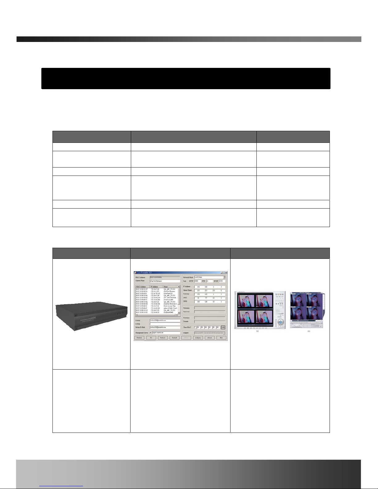
2.2. Preview
iCanServer540R IP-Installer iNVR
iCanServer540R
Recording Video Server
PC software to allocate an IP
address to the iCanServer540R
PC software to view and record
the A/V streaming data
transmitted from
iCanServer540R and controlling
DVR mode operation of
iCanServer540R.
Rev.1.0 (Nov. 2006)
8

iCanServer540R User’s Guide
2.3. Physical description
2.3.1. Front panel
Figure 2-1. Front panel of iCanServer540R
y URGENT Switch
Press this button switch to start or stop manual recording in urgent condit ion. The recording
status will change upon pressing the switch. There are two pins to con nect extended switch
for the same purpose at the rear panel.
y Status indicator:
There are three status indicator LEDs. They are HDD, LAN and Power from the left.
HDD : HDD lamp lits on when HDD is being accessed.
LAN : Link indicator, continuous green light means that LAN is in normal state. When there
is traffic on the LAN, orange light flickers.
Power : Status indicator shows the status of the iCanServer540R in three different colors.
1 Green : The green light indicates that the iCanServer540R is operating properly. If the
green light is continuously on, it means that the iCanServer540R is ready to
transmit data via network. If the green light blinks, it means that there is
traffic between LAN and iCanServer540R.
2 Red : The red light indicates that the hardware of the iCanServer540R is not operating
properly.
3 Orange : The orange light indicates that the software of the iCanServer540R is not
operating properly.
When applying power to iCanServer540R, power indicator temporarily lights on
with red color and then returns to green. This is the normal condition.
Rev.1.0 (Nov. 2006)
9
iCanServer540R User’s Guide
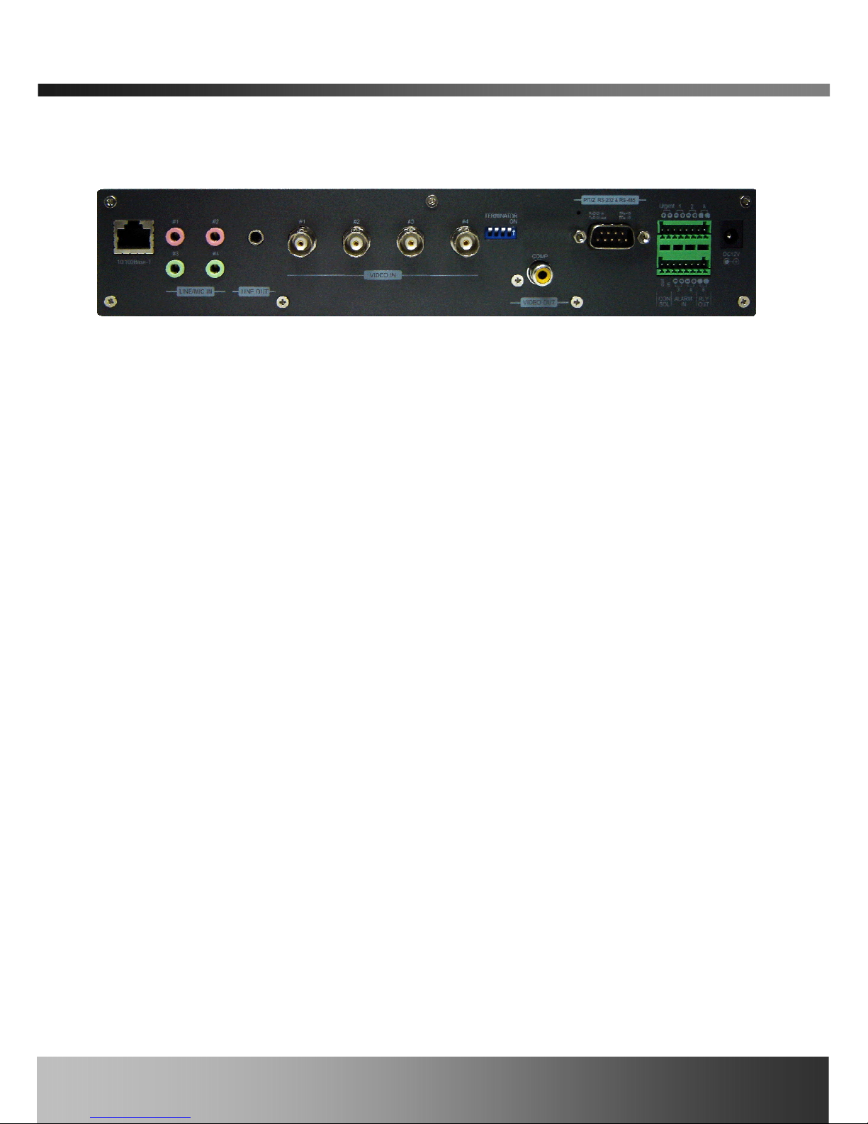
2.3.2. Rear panel
Figure 2-2. Rear Panel of iCanServer540R
y 10/100base-T : 10/100 Mbps Ethernet connector (RJ-45).
y Line/Mic In (#1-#4) : They are used to connect external audio source or microphone to
iCanServer540R. There are 4 Line/Mic. In connectors.
Use Standard stereo earphone jack for the connection.
y Line Out : It is used for connecting external speakers with built in amplifier. Audio from
remote site is output through Line out in bi-directional audio mode.
Use Standard stereo earphone jack for the connection.
y Video1- Video4 : 4 Video input (composite NTSC, PAL, SECAM)
y Terminator : Enable termination by 75 Ohm resister for each video input when switched on.
Leave the terminator to ON position when no other device is sharing the same
video line. If the the specific video is sharing same video with other devices
and located at mid position along video line, leave the terminator to OFF
position.
y COMP : Live video from the camera can be displayed on a local monitor with Composite
vidoe input. To use Composite video monitor, go to Admin -> Basic Set Up ->
Output Video Type to select “Composite”.
y Factory Default Button : It is used for resetting iCanServer540R to shipment state from
factory. Factory Default Button is hidden underneath a tiny
hole located at the upper left part of P/T/Z RS-232 & RS-
485 connector. Press the button by tools having sharp tip.
y P/T/Z RS-232 & RS-485 : It is used for connecting P/T/Z device with RS-232 or RS-485
interface standard. Pin assignments are
Pin 2 – RS-232 In
Pin 3 – RS-232 Out
Pin 5 – RS-232 GND
Pin 8 – RS-485 Negative (-) input
Rev.1.0 (Nov. 2006)
10

iCanServer540R User’s Guide
Pin 9 – RS-485 Plus (+) input
y CONSOL : It is used for connecting RS-232 type terminal for manufacturing purpose. Out
and In pins corresponds with Tx and Rx pins, respectively. Any of “-“ pin in Alarm In
can be used as ground pin for the connection.
y URGENT
Connect a remote switch that can be used as a “URGENT” switch.
y Relay out : It is used for connecting external alarm generators such as sirens, flashing light,
etc. When activated, relay output configures a closed circuit. Two Relay
outputs(A, B) are provided.
y Alarm Input : There are provisions for 4 alarm sensor device connections. They are used
for connecting external alarm sensors such as the infrared sensors, heat
sensor, magnetic sensors, etc.
y Power Connector: Power input of iCanServer540R. 12V/3A
2.4. PC Requirements
AV streaming data from iCanServer540R can be observed through iNVR program which is a
viewing & recording program running on a PC. Minimum requirement of the PC is described
below:
Items Minimum Recommended
CPU Pentium III 700 Pentium IV 1.2G above
Main Memory 128 MB 256MB above
Operating system* Windows 2000 Windows 2000 or later
Web browser Internet Explorer 5.0 Internet Explorer 5.0 or later
Resolution 1024 X 768 1600 X 1200
Network 10 Base-T Ethernet 10/100 Base-T Ethernet
* Operating Systems supported : Windows NT Workstation 4.0 (SP 5.0 OVER)
Windows 2000 Professional
Windows XP Professional / Windows XP Home Edition
2.5 Quick Installation Guide
Brief information for rapid installation is provided in this section. For more detailed information
you are recommended to refer to pertinent documentations provided with the product or refer to
Rev.1.0 (Nov. 2006)
11

iCanServer540R User’s Guide
iCanTek’s home page (http://www.icantek.com).
1. Install “IP installer” and “iNVR” on your PC.
Detailed information for installing these programs can be found in [IP-Installer User’s
Guide] and [iNVR User’s Guide], respectively.
2. Assign IP address to iCanServer540R using IP installer.
Identify the type of the network environment and set up IP address. Detailed process of
setting up IP address can be found in [IP-Installer User’s Guide]. If network type is
xDSL or Cable modem you need supplementary information provided by your ISP.
3. Connect to iCanServer540R in Administrator Mode for initial parameter set-up.
All parameters are set to factory default state when iCan Server540R is delivered to you.
You are asked to configure the system for your environment in administration mode.
Detailed information of using administration mode can be found in [5. Configuring the
A/V Server in Administrative Mode]. Among the parameters, the parameters in the
following table should be set-up in proper values. Detailed information for the parameters
in Administrator Mode be found in [5. Configuring the A/V Server in Administrative
Mode]
[Note]: Set-up values are preserved even the power is turned off.
Page Parameter Setup value Factory default value
Basic
Setup
Max Upload
Bandwidth
Set this value lower than
allowed upload bandwidth.
10Mbps
Max Users
Number of users you want to
allow
10users
User
Admin &
Time
Setup
Administrator name
& password
For safety, you are
recommended to change
these values from factory
default. For new connection,
you need to input changed
values for corresponding
fields. Do not expose these
values to others and
memorize these values.
Username : root
Password : dw2001
Current Time
Input correct time to this
field.
2001/1/1
4. Connect the inputs and output signals to iCanServer540R.
Rev.1.0 (Nov. 2006)
12

iCanServer540R User’s Guide
iCanServer540R does not function properly if there is no video and audio input.
Refer to the following table. You have to connect at least one Video In.
Connectors Function Signal description Number
Video In
Input video
connector
Analog video outputs from analog
CCTV camera, DVD, TV etc.,
(NTSC/PAL/SECAM)
1 to 4
Line In/Mic Audio in
Microphone or output from audio
devices.
1 to 4
Line Out
Audio out for
speaker
When in bi-directional audio mode,
Audio signal from remote site is
available from this connector. Use
speaker with amplifier.
1
Alarm IN
Connecting
Alarm Sensor
IR sensor, Motion Sensor, Smoke
Detector…
1 to 4
RLY Output
Connecting
Alarm alerting
device
Siren, Flashing Light… 1 to 2
RS485
PTZ device
control
Output signal controlling PTZ device
5. Video connection to iCanServer540R
You can connect to iCanServer540R in video mode by running “iNVR” program on your PC.
Detailed information of using “iNVR” can be found in [iNVR User’s Guide].
You also can connect to iCanServer540R for video and audio streaming via a conventional web
browser such as Internet Explorer by typing the IP address assigned to iCanServer540R into the
browser.
Rev.1.0 (Nov. 2006)
13
iCanServer540R User’s Guide
3. Connecting iCanServer540R to Network
iCanServer540R supports LAN, xDSL, and Cable modem. It also supports shared IP environment
where single IP address is shared by at least 2 IP devices. Refer to [IP-Installer User’s
Guide] for details of setting the IP address for iCanServer540R.
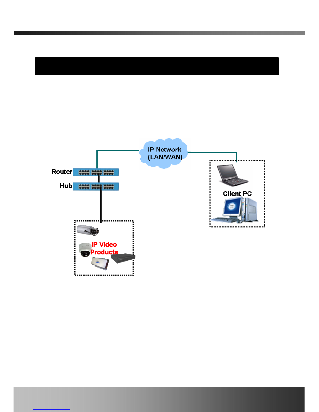
3.1. Connecting to LAN
In case of connecting the iCanServer540R to LAN, it is generally connected as in Figure 3-1.
Figure 3-1. Connecting the iCanServer540R to LAN
1. Follow through steps 1 to 4 in Section 2.5 to assign IP address to iCanServer540R.
2. Install iCanServer540R and connect it to desired LAN.
3. Check if you can receive video data when connecting to iCanServer540R using the viewer
program.
4. When one or more IP video products are connected through a IP sharing device (i.e. router) to
a larger network (i.e. the internet), in order to access each unit from outside the local area
network, each device must have a unique RTSP (Real Time Stream Protocol) and HTTP port
number. You must also configure your IP sharing device for “port forwarding”. This is to enable
Rev.1.0 (Nov. 2006)
14
iCanServer540R User’s Guide
the IP sharing device to forward packet data with unique port number (RTSP and HTTP) to unique
internal IP address (local IP address). If you only plan to access multiple units from within a local
area network, you do not need to change the RTSP and HTTP port numbers, unless other IP
sharing devices sit in-between the client and the IP video products. For more detailed information
regarding the use of IP sharing device refer to the document [Use of Private IP network using
IP-sharing-device].
②
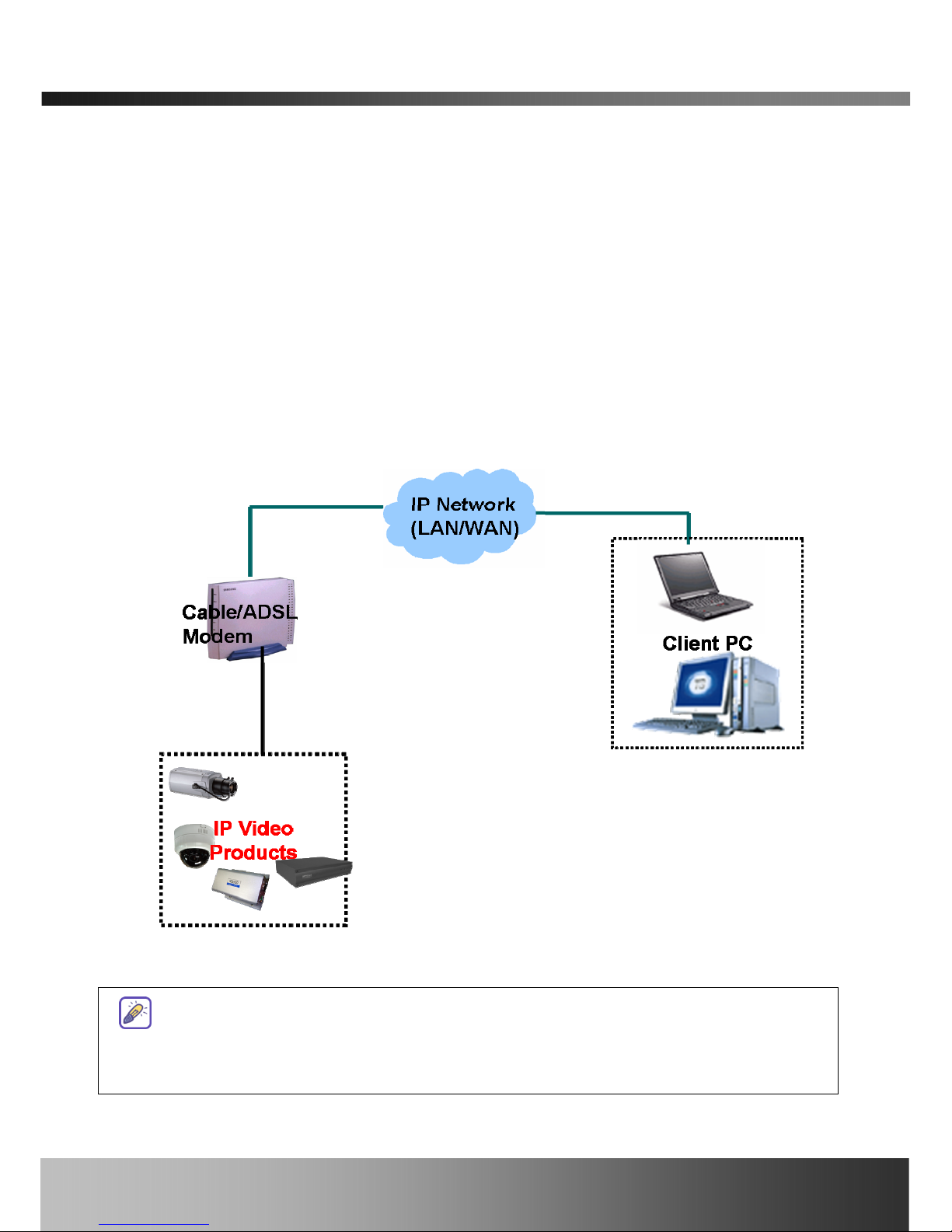
3.2. Connecting to xDSL/Cable Modem
1. Follow through steps 1 to 4 in Section 2.5 to assign IP address and other network parameters
to iCanServer540R.
2. Install iCanServer540R and connect it to xDSL or Cable modem as in Figure 3-2.
Figure 3-2. Connecting the iCanServer540R to ADSL Modem
When fixed IP address is assigned to the xDSL or Cable modem, follow the same way as
assigning IP address for the case of LAN using IP-installer. To enable the notification of the
changed IP address to the user over e-mail when the IP address is changed in floating IP
Rev.1.0 (Nov. 2006)
15

iCanServer540R User’s Guide
environment, you have to assign the e-mail address when user name and password are
input using IP-installer. (Management server provides a convenient way of
connecting to your video server under dynamic IP environment. Please refer to
the Application note regarding “Management Server” in the CD.)
When connecting iCanServer540R to xDSL or Cable modem, usually regular LAN cable
is required. But since some modems has crossover connections, please contact your
service provider for detailed information.
Rev.1.0 (Nov. 2006)
16

iCanServer540R User’s Guide
Rev.1.0 (Nov. 2006)
17
4. IP-Installer
iCanServer540R needs an IP address for connection to the network(Internet/Intranet). IPInstaller is a PC program developed to assign IP address and setup network parameters to digital
video security network products such as Network Camera and A/V Server from iCanTek. IPInstaller is provided in a CD supplied with iCanServer540R or it can be downloaded
from” www.icantek.com
”.
Detailed information of Installing and running IP-installer can be found in [IP-installer
user’s guide] in the CD provided with the unit.
4.1. Main window of IP-Installer
Figure 4-1. IP-Installer

iCanServer540R User’s Guide
5. Configuring the A/V Server in Administration Mode
5.1. Log On
There are 2 ways of connecting to iCanServer540R administrative mode. One is through standard
internet browser and the other is through “iNVR” program.
5.1.1. Using Internet Explorer
You can log on to the server by clicking admin mode button or from your internet browser.
Type in as the f ollowings in the address window of the internet explorer.
http://[iCanServer540R IP address]/admin.htm
Example: http://172.16.64.33/admin.htm
If you changed the HTTP port from default value you can login by typing in:
http://[iCanServer540R IP address]:[port]/admin.htm
Example: http://172.16.64.33:8080/admin.htm
5.1.2. Log on from “iNVR”
Select video channel in the viewing window of “iNVR”. Selected video channel will be
highlighted. Click
button on the right side of the display screen.
Figure 5-1. Main Screen (A) and DVR control Screen (B) of “iNVR”
Rev.1.0 (Nov. 2006)
18

iCanServer540R User’s Guide
5.1.3. Controlling DVR
When iCanServer540R is connected through iNVR or internet browser, it is connected as an A/V
server, i.e., it functions as a real-time A/V streaming server to the client. A user having the
authority of administrator can enter into DVR control mode by pressing
button. By
pressing this button the DVR administrator will have a screen as shown in Fig.5.1(B). For security
purpose only one user is allowed to be connected as a DVR administrator. Refer to [iNVR user’s
guide] in the CD provided with the unit.
(When connected by the web browser, DVR Control Mode funct ion is NOT available.)
5.1.4. User ID and Password
iCanServer540R prompts for User Name and Password to enter into administrative mode as in
Figure 5-2.
Figure 5-2. Log On Screen
Factory default User Name and Password are set as ‘root’ and ‘dw2001’, respectively. Click on
“OK” button to enter into the Basic Setup page of Admin Mode. If you have changed the username
and password of the Administrator, you must log on with the changed username and password.
Rev.1.0 (Nov. 2006)
19

iCanServer540R User’s Guide
5.2. Basic Setup
Setup the basic parameters of the iCanServer540R.
Field/Button
Sub Field
/Button
Description
Language
Select a language of your choice
System Name
Logical name of the iCanServer540R. It is same as the one
set-up by IP-installer. You can reassign the system name.
Figure 5-3. Basic Setup
Rev.1.0 (Nov. 2006)
20

iCanServer540R User’s Guide
Enable OSD
Time
Check at the box for enabling OSD display of the time from
the server.
Audio Input
Selection
Select the type of input audio.
z Select Line In for using Line-out from audio devices.
z Select Mic for using microphone.
Video Quality
& Bandwidth
Control
Input Video
source
Select video type of your area. (PAL, NTSC, SECAM)
Video Size
Select video size for transmission-
z NTSC(30 frames/sec Max.) : 176x144 / 352x240 /
704x480.
z PAL/SECAM (25 frames/sec Max.) : 176x144 /
352x288 / 704x576
Description Assign names for each channel.
Max upload
rate
Assign maximum bandwidth of the uplink for the network
connected to iCanServer540R.
Frame rate
Assign number of video frames to be transmitted for each
second. You can improve picture quality by lowering frame
rate for the same bandwidth.
Video rate Assign bandwidth for transmitting video data.
Audio rate
Assign bandwidth for transmitting audio data. Audio data is
not transmitted if you select “NA”
Video
Rotation
Check at the box for rotating video by default.
Enable high
quality
recording
Select this mode when your network is a low speed network
that cannot assure enough bandwidth to send high quality
video to users. When this mode is selected, dual mode
streaming is enabled to provide high quality video recording
on the HDD while providing lower quality on-line streaming
video to connected users. Check the box at the left and select
the recording type to apply this feature from manual and
schedule. Alarm recording is set to apply high quality
recording mode always. Finally select the bit rate of recording.
Usually bit rate above 600Kbps provides good quality to the
users. Once selected to use this mode, you can independently
set the scheduled or manual recording to be high quality by
checking at the corresponding check box.
Rev.1.0 (Nov. 2006)
21

iCanServer540R User’s Guide
Recording
rate
Assign bit rate for high quality recording.
Check
After you finish set up of video and audio for all the channels,
click on this box to obtain the possible maximum number of
users (Possible Max Users) and remaining network
bandwidth (Remained) remaining when possible maximum
users are connected.
Possible Max
Users
It shows the number of maximum simultaneous connections
for the network connection set-up.
Remained
It shows the network bandwidth remaining when Possible Max
Users are connected.
Limited users
Useful network bandwidth varies according to the condition of
the network. This parameter is used to limit the number of the
simultaneous connections below the number shown in Possible
Max Users.
Save
Save the set-up parameters when the set-up parameters are
done.
Rev.1.0 (Nov. 2006)
22

iCanServer540R User’s Guide
5.3. Network Configuration
Setup the network parameters appropriately in accordance with your network environment. Many
of the parameters in this page is same as those used setup by “IP-Installer”.
Figure 5-4. Network Configuration
Rev.1.0 (Nov. 2006)
23

iCanServer540R User’s Guide
Field/Button
Sub Field
/Button
Description
IP Assign Type
The network types supported by the iCanServer540R are
LAN(fixed IP), PPPoE, and DHCP(automatic IP allocation)
Static IP Setup
When the network environment is fixed IP, select ‘LAN’ in
the network type, and put the IP address, Subnet Mask,
Gateway, DNS1 and DNS2. Ask your network
administrator or ISP for the information. DNS2 is used
when DNS1 does not work.
PPPoE Setup
When the network environment is PPPoE and IP address is
assigned automatically, select ‘PPPoE’ in the network type.
Next, fill in the ‘User Name’ and ‘Password’ fields with the
values assigned by the ISP.
DHCP Setup
When the network environment is “automatic IP allocation
by DHCP”, select ‘DHCP’ in the network type. For cable
modem connection, select this mode.
Refer to [IP-installer user’s guide] for “Host name and
domain for Cable Modem
Clone MAC Refer to [IP-installer user’s guide] for “Clone MAC”
E-Mail Setup
Notify for IP Change
If you check this, the IP address will be sent via E-mail
whenever the IP address changes. It is sent to the E-mail
address set by “Recv E-Mail Address”.
Recv E-Mail Address
Enter E-mail address to receive information sent from
your video server. This is same as E-mail field in IPinstaller.
Return E-
Mail Address
Fill in this field with correct e-mail address to identify the
mail sent from the video server
Using Built-
in SMTP Server
If you are using web mail services having no SMTP server,
check the radio button at the left of “Using Built-in
SMTP Server” and enter valid e-mail address to avoid
spam filtering on the receiving e-mail server.
Using External
SMTP Server
If you are using external mail server, fill in the fields with
proper parameters.
Port Change
HTTP
HTTP port is used for the connection to the admin page.
Default is 80.
RTSP The RTSP port is used for transmitting real time
Rev.1.0 (Nov. 2006)
24

iCanServer540R User’s Guide
audio/video data from the video server. Default is 554.
WebHDD
A part of the HDD can be used to store user’s data. This is
the port number for accessing the space. Default value is
6971.
Management
Server
You can register the video server to the Management
Server (DDNS Server) for name service to your video
server.
Log on to server
Check this box to enable log on to the management
server. By log on to the management server your video
server can use domain name instead of numeric IP
address. This feature is particularly useful when your
video server is using dynamic IP address. Input valid
management server (DDNS Server) name for the service.
You must have an account on the management server
(DDNS Server) and register your IP video devices under
your account to use this feature.
Domain name of your video server can be assigned when
you register your video server to the management server
under your account.
One of the servers available is mgmt.net-video.net. For
opening an account, visit www.net-video.net
.
IP Filtering
You can restrict the access to the administrator page from
IP addresses beyond certain IP address range.
Restrict
Administrator
Access
Check at this box to restrict administrative log on.
Base IP Address
Input IP address of the PC which is intended to be used
for log on to administrative mode.
Mask
This is same as subnet mask. It is used to allow
administrative log on only to the PCs located in the same
subnet as the base IP address. If you want to allow only
one PC to access in administrative mode, set this value to
255.255.255.255.
Rev.1.0 (Nov. 2006)
25

iCanServer540R User’s Guide
5.4. User Admin & Time Setup
You can change the ID and password of users and also assign different attributes for each user.
Figure 5-5. User Admin. & Time Setup
Field/Button
Sub Field
/Button
Description
User
Administration
Administrator
Username
Admin ID. Default ID is “root”
Rev.1.0 (Nov. 2006)
26

iCanServer540R User’s Guide
Administrator
password :
Admin password. The default password is “dw2001”.
Administrator
Confirm
Password
Enter the password once more to confirm the password.
Add User
Username
Enter the user ID you want to add. Up to 100 users are
supported by iCanServer540R.
Add User
Password
Enter the user password.
Add User
Attribute
You can set different system resource access capabilities for
each of the users.
z Attributes are Audio, Bi-directional Audio and Pan/Tilt
control.
z For example, if you want a specified user to hear the
audio from the iCanServer540R, check Audio in the
check box.
User List
You can list “user ids” and “ their attributes” here.
z format : user id[A, BA, P] :
A – audio,
B – bi-directional audio,
P – pt(Pan/Tilt), attribute.
You can delete specific user by clicking the DELETE button.
Authentication
for Viewing
YES
SAVE
If you want to restrict viewing access to the iCanServer540R,
check at the box left to Yes and click on Save. Users need to
input ID and password to connect to iCanServer540R in viewing
mode in a pop up window as shown below..
Figure 5-6. User Authentication in iCanServer540R
If No, default
attribute
If you uncheck for the Authentication for Viewing, all users can
access the iCanServer540R with the same attribute set here.
Rev.1.0 (Nov. 2006)
27

iCanServer540R User’s Guide
Checked attributes are enabled. Click “Save” to save the
attribute.
Time Setup
Current Time It shows you the current time of iCanServer540R.
Synchronize
with an
Internet
Time Server
Synchronize the time with the internet time server at the right.
When the time server is out of the reach from iCanServer540R,
you can assign time server by filling in Specific Time Server
field.
Synchronize
With this
Computer
Time
Synchronize the time with the time of the PC.
Set Manually Set the time manually. Fill in the fields with desired formats.
SAVE Save the set up parameters
If you lost Administrator’s ID and password, the only means of recovery is to reset
the settings to factory default, but then you lose your previous settings.
Rev.1.0 (Nov. 2006)
28

iCanServer540R User’s Guide
5.5. Sensor & Capture Setup
This is the setup page for conditions of video capture. The video capture can be triggered either
by activated alarm sensor or motion detection as setup by this page. When the video capture
condition is med, the situation is notified to users through iNVR. Captured video is stored on the
HDD of the iCanServer540R.
Figure 5-7. Sensor & Capture Setup
Field/Button
Sub Field
/Button
Description
Sensor Setup
Sensor 1, 2,
3, 4
Select sensor type. There are two types of sensors which are
Normal Open and Normal Close.
Enable Urgent
Recording
Check at the box to enable recording by pressing the URGENT
switch.
Video Capture
Condition
The iCanServer540R supports 2 types of conditions which are
Rev.1.0 (Nov. 2006)
29

iCanServer540R User’s Guide
mutually independent.
1. Sensor initiated: when at least one of the sensor
detects alarm condition.
2. Motion-Detection initiated : when motion is
detected from video channel
Sensor
Select
Check at corresponding check box to enable Sensor initiated
capture.
Motion
Detection
Select
Check at corresponding check box to enable motion detection
initiated capture.
Captured
Video
Transmission
Select a way of sending captured video. You can send captured
video through E-mail or record the data into HDD, or both.
-
By E-Mail
Check to send captured video by e-mail.
E-mail is sent to the Recv E-mail address. Refe r to [Section
5.3.]
Captured video data for E-mail consists of intra frames only in
consideration of the limited storage space for E-mail account.
FTP data contains entire video frames.
SAVE Save the setup parameters.
Rev.1.0 (Nov. 2006)
30

iCanServer540R User’s Guide
5.6. Alarm Device Setup
Test alarm output and describe the condition of alarm.
Figure 5-8. Alarm Output Setup
Field/Button
Sub Field
/Button
Description
Alarm Device
Test
Test alarm devices. Click on On/Off for testing
Small box with white background indicates the status of the
relay by On/Off.
ON On the alarm output (close the relay contact)
OFF Off the alarm output (Open the relay contact)
Alarm Device
Active
Condition
Device 1, 2
Setup the condition of activating each alarm device. Select
sensor or motion detection as the condition.
Sensor 1, 2,
3, 4
Check at the box at the left of to allow alarm generation upon
sensor input.
Ch n Motion
Check at the box at the left to allow alarm generation upon
Motion detection on Channel n.
Duration Set the duration of Alarm annunciation.
Rev.1.0 (Nov. 2006)
31

iCanServer540R User’s Guide
10 sec, 30 sec, 1 min, 2 min, 5 min, 10 min, 30 min, 1 hour.
SAVE Save the setup parameters.
Rev.1.0 (Nov. 2006)
32

iCanServer540R User’s Guide
5.7. Motion Region Setup
Set the motion detection regions. Up to 3 regions can be defined.
Figure 5-9. Motion Region Setup
Field/Button
Sub Field
/Button
Description
Channel
Selection
Select the channel to apply the settings.
Channel
Sensitivity
Set the sensitivity in motion detection for each channel. 1 is the
most sensitive, and 10 is the least sensitive.
Rev.1.0 (Nov. 2006)
33

iCanServer540R User’s Guide
Motion Region
Setup
Set up to 3 the motion detection zone
Region 1, 2,
or 3
Enable each zone by checking at the box at the left of each
Region.
. To set the region,
1. Click on START and click on a box overlaid on the
video
2. Click on END and click on a box overlaid on the video.
3. The defined motion detection zone will be indicated
with corresponding colors.
Legend of the color :
red(region 1),
green(region 2),
blue(region3).
START Enable selection of rectangular zone start.
END Enable selection of rectangular zone end.
SELECT Click on this button and click on desired rectangle to add or
delete the rectangular region to the motion detection zone.
Percentage This value controls the sensitivity of each region.
1 is the most sensitive and 100 is the least sensitive
RESET Clears the start & end point to (0,0) & (0,0)
SAVE Save the setup parameters.
Rev.1.0 (Nov. 2006)
34

iCanServer540R User’s Guide
5.8. PTZ Setup
Setup and test the PTZ devices.
Figure 5-10. PTZ Setup
Field/Button
Sub Field
/Button
Description
Channel
Selection
Select the channel to apply the settings.
PTZ Model
Selection
Choose the PT model.
Refer to section 5.9 for the addition of PT protocol data.
Delete Button Press this button to delete the PTZ model at the left.
PTZ Device ID Your PT device needs an ID, input ID in this field.
Rev.1.0 (Nov. 2006)
35

iCanServer540R User’s Guide
Click on SAVE to save the ID.
PTZ Operation
Check
PAN Step Adjust the panning step.
TILT Step Adjust the tilting step.
ZOOM Step Adjust the zooming step.
Left/Right/Up/Down
ZIN/Auto
Focus/ZOUT
You can check various operations of the PTZ devices.
“Left”/”Right”/”UP”/”DOWN/Zoom In/Zoom Out/Auto
Focus”
PTZ Position
Setup
You can set up the PTZ limitation & preset positions if the
PT device supports it.
Panning Limitation
Set the left/right limitation and t est.
Select Left/Right position before setting.
Panning Limitation
RESET
Clear the panning limitation previously set.
The panning range will be the same as the PT device
allows.
Panning Limitation
SET
Set the present position as left or right panning limitation.
Panning Limitation
TEST
Test the panning limitation which was set previously.
Preset Position : Set the preset position and test.
Preset Position
Preset & Move
Select a preset position to move to. Movement to the
preset position will be made upon clicking on “MOVE”
Preset Position
Name Set
Assign logical name for the preset position. Enter into the
field and click on SET.
Preset Position
Set
Set the present position as a preset position with position
number shown at the right of “Preset & Move” and name
shown at the right of “Name Set”.
Rev.1.0 (Nov. 2006)
36

iCanServer540R User’s Guide
5.9. Upgrade & Reset
You can upgrade the iCanServer540R via the network.
Figure 5-11. Upgrade & Reset
Field/Button
Sub Field
/Button
Description
System S/W
Upgrade
Upgrade the system software installed in the video server via
the network. System software needed for the upgrade can be
downloaded from iCanTek’s home page.
Refer to [6.4. How To Upgrade Your iCanServer540R
System].
Bootloader
Upgrade
Upgrade the bootloader installed in the video server via the
network. Bootloader needed for the upgrade can be
Rev.1.0 (Nov. 2006)
37

iCanServer540R User’s Guide
downloaded from iCanTek’s home page.
Refer to [6.4. How To Upgrade Your iCanServer540R
System].
Add PTZ File
Add a new PT driver software via the network. PT driver can be
downloaded from iCanTek’s home page.
Refer to [6.4. How To Upgrade Your iCanServer540R
System].
Factory
Default
Setting
Re-initialize the video server to factory default state.
By checking on a Radio button “Except Network Configuration”,
you can preserve the parameters for the network. Checking on
“All”, will return all the parameters to factory default state.
Once iCanServer540R is re-initialized as factory default
state, it should be set-up again using IP-Installer.
System Reset
Perform remote reset by clicking the “CONFIRM” button.
All previous connections will be disconnected upon
reset. iCanServer540R does not resume the connections
and the users must re-connect to the server manually.
HDD Format
The HDD on iCanServer540R is formatted. A small HDD area
reserved for storing user’s data (WebHard) is not affected by
the formatting to preserve user’s data stored in this area.
Rev.1.0 (Nov. 2006)
38

iCanServer540R User’s Guide
5.10. Status Report
It shows you system records since the system started.
Figure 5-12. Status Report
You can check the problems as well as the versions and event status of the whole system and
each module.
Rev.1.0 (Nov. 2006)
39

iCanServer540R User’s Guide
6. Tips for Using iCanServer540R
6.1. Alarm Input/Output
The Alarm In/RLY OUT Connector is used to connect the various sensing and alerting devices.
Examples of sensing devices are infrared sensors, motion sensors, heat/smoke sensors, magnetic
sensor, etc. Examples of alerting devices are loud speaker, flashing light, etc
1. Alarm Input(ALARM IN)
Connect the two wires of the sensors. The sensor type can be set in Administrative
Mode(Ref. 5.5 & 5.6). Output lines providing on-off switching are connected between
“In-“ and “In+” pins. Figure 6-2 shows the input circuit of “Alarm In”.
Figure 6-1. Alarm input circuit of iCanServer540R
2. Alarm Output(RLY OUT)
Alarm output is configured as a relay circuit. Relay circuit is normal open and circuit is
closed upon alarm output. The relay is capable of switching 30V/2A electrical signal.
Rev.1.0 (Nov. 2006)
40

iCanServer540R User’s Guide
External Power
External Alarm Device
Figure 6-2. Alarm Output of iCanServer540R
6.2. Trouble Shooting
1. After iCanServer540R is successfully installed.
• iCanServer540R in viewing mode, neither channel name nor video is display and
eventually timeout message is shown up.
Check the power and network connection of iCanServer540R.
To check if the network is properly operating, open the browser and try to connect to
any server.
Example) http://www.icantek.com
Or open the MS-DOS Prompt and type the following.
ping www.icantek.com
Then press Enter. If you see the “ Reply fro m …” message it means that the network is
working properly. To check if the iCanServer540R is connected, open the MS-DOS
Prompt and type the following.
ping [the IP of the server]
Example) ping 192.168.1.112
If you see the “Reply from …” message, it means that the server is properly connected.
If you do not see a Reply message, check if the network cable and power cable are
properly connected.
Rev.1.0 (Nov. 2006)
41

iCanServer540R User’s Guide
• Name of the channel on iCanServer540R is displayed but there is no video.
Check if there is input video source to the channel. And check if there is a firewall in the
network. Check if the network is NAT type.
In case there is a firewall in the network:
Try a TCP connection. TCP connection is usually enabled by checking TCP box before
connecting to iCanServer540R. Refer to viewer manual for more detailed operation.
If the network is NAT type, you need port mapping. It is be achieved by setting the NAT
server to forward all packets coming in through a specific port to iCanServer540R.
2. After Successfully Connecting to the iCanServer540R
• Video movement is slow.
z In Basic Setup of Admin Mode, lower the “Quality”. High quality means more data.
You can also set the “Max. Bandwidth” to higher value. But this value must be lower
than the maximum upload speed of your network. For example, if the maximum
uploading bandwidth of the network is 400Kbps, set the total “Max. Bandwidth” of the
4 channels to 384Kbps. If you set it higher, the video image can be corrupted with
artifacts.
Ask your network manager or ISP for maximum uploadin g bandwidth of the network.
z Check whether dual streaming mode is enabled and iCanServer540R is recording
video. Dual streaming mode is enabled by selecting “Enable High Quality Video
Recording” in basic set-up page (Refer to Section 5.2). When dual streaming mode is
enabled, iCanServer540R provides low speed video to connected user while recording
high quality video into HDD.
• The image is dull and I see green, pink dots.
This could be caused by performance limitation of the PC. Do not run too many programs while
running viewer program. The other reason could be missing data while transmission from
Rev.1.0 (Nov. 2006)
42

iCanServer540R User’s Guide
iCanServer540R.
• Mosaic phenomenon.
Mosaic phenomenon occurs when not enough network bandwidth is available considering the
resolution and frame rate of the video.
Example is 704x480 video with low Max. Bandwidth.
Users are recommended to adjust resolution and frame rates to lower values for lower
bandwidth network.
3. How can I maintain high quality video recording when I’m using low speed network
iCanServer540R has Dual streaming mode that enables high quality video recording on the HDD,
while providing lower quality video to on-line users. This f eature is enabled by selecting “Enable
High Quality Recording” in basic set-up mode. (Refer to 5.2 for more detailed information.)
6.3. Web Viewer
iCanServer540R can be connected through internet explorer, for the connection enter the IP
address of the camera into the IP address window of the internet explorer.
Figure 6.3 shows the screen for the web viewer. Explanations on the buttons and status
indicators are shown in Figure 6.4.
Rev.1.0 (Nov. 2006)
43

iCanServer540R User’s Guide
Figure 6.3. Web viewer.
Rev.1.0 (Nov. 2006)
44

iCanServer540R User’s Guide
Figure 6.4. Explanations of the buttons and status indicators for the web viewer.
6.4. How To Upgrade Your iCanServer540R System
1. Log on to administration mode and select “Update & Reset” menu.
2. Click "Browse..." to find the files you want to use for upgrade. This will open a "Choose file"
dialogue window. The file extension is “ief”.
3. When you've found the file, click "Open." This will select the file and close the "Ch oose file"
dialogue window.
4. Click the "INSTALL" button. An alert message box will pop up. Click “OK” button then it will
start uploading the file. This may take some time.
5. Upgrade completion message will appear after the system upgrade has been completed.
6. Reboot iCanServer540R by performing “System Reset”.
7. After rebooting, log on to the administration mode again and click the “Status Report” in the
Rev.1.0 (Nov. 2006)
45

iCanServer540R User’s Guide
left side.
8. Check the version and release date of the iCanServer540R ™.
You can download iCanServer540R system software from
iCanTek’s homepage.
http://www.icantek.com
Rev.1.0 (Nov. 2006)
46

iCanServer540R User’s Guide
6.5. How to Replace Hard Disk on iCanServer540R
iCanServer540R has a hard disk that can be replaced when needed. To replace the hard disk
follow the procedures described below.
1. Remove the 4 screws joining the front panel to the body of iCanServer540R.
2. After removing the front panel you can find power cable and IDE flat cable connected to the
hard disk at the center of the housing.
3. Unplug the cables from the hard disk.
Rev.1.0 (Nov. 2006)
47

iCanServer540R User’s Guide
4. At the bottom of the housing, there are 4 screws. Remove the screws.
5. Tilt the housing slightly to the front. The hard disk will be slided out.
6. Slide in a new hard disk and follow the reverse procedure to install the hard disk into
iCanServer540R.
7. If a hard disk is a one that has never been used for iCanServer540R, you need to format the
hard disk using format command of iNVR. In order to format the hard disk, you should run
Rev.1.0 (Nov. 2006)
48

iCanServer540R User’s Guide
‘iNVR’, click on it, and select to format the hard disk. Refer to [iNVR’ user’s
guide] for more information.
Rev.1.0 (Nov. 2006)
49
 Loading...