

Page 1
Jul 2016
Page 2

Page 3

C
ONTENTS
1 INTRODUCTION 5
2 SOFTWARE INSTALLATION 8
2.1
NEW INSTALLATION OR UPGRADE 8
2.2
START OF THE INSTALLATION 9
2.3
FINALIZING THE INSTALLATION 11
2.4
INSTALLATION OF THE ‘TRINITY’ MEASURING HEAD AND ITS CALIBRATION 12
3 GETTING STARTED 13
3.1
SYSTEM SETUP 13
3.2
FIRST STARTUP OF THE APPLICATION 15
3.2.1 Absolute path to the machine tool database 15
3.2.2 Add the Console application as a rule to the windows firewall 16
4 APPLICATION 18
4.1
STARTUP 18
4.2
APPLICATION SETTINGS & NETWORK SETUP 19
4.2.1 The “Probe Selection” field 20
4.2.2 “CONNECT” button 20
4.2.3 “SETTINGS” button 21
4.2.3.1 Change the password 22
4.2.4 “CONTINUE” button 23
4.2.5 “SYNCHRONIZE” button 23
4.2.6 “EXIT” button 23
4.3
NC CODE 24
5 DATABASE 25
5.1
OPENING THE DATABASE FOR EDITING 25
5.1.1 Create Local Machine 26
5.1.2 Edit Local Machine 28
5.1.3 Remove or delete a Local Machine 28
5.2
PARAMETER SETTINGS 29
5.2.1 Parameter setting for “Position Inspector” 29
5.2.2 Parameter setting for “Rotary Inspector” 31
6 ROTARY INSPECTOR AND RI DATA MANAGER 32
6.1
SETTINGS 33
6.2
OPENING THE DATABASE FOR EDITING 34
6.2.1 Locate Global Database 35
6.2.2 Create Local Machine 36
6.2.2.1 Creating a local machine from the global database 36
6.2.3 Edit local machine 39
6.2.4 Remove/Delete local machine 39
6.2.5 Link local machine to global database 39
6.2.6 Synchronize with Global Database 41
APPENDIX A DATABASE 42
A.1 DATABASE 42
A.2 CONSOLECONFIG.INI FILE 44
APPENDIX B OPERATION IN A ´.LOCAL´ DOMAIN 45
APPENDIX C PASSWORD 49
APPENDIX D OUTPUT DEFINITION PARAMETERS 50
D.1 OVERVIEW ROTARY 50
D.1.1 Rotary Analyzer (RA) 50
D.1.2 Rotary Inspector (RI) 51
D.2 OVERVIEW LINEAR 51
D.2.1 Position Analyzer (PA) 51
D.2.2 Position Inspector (PI) 51
Page 4

APPENDIX E HARDWARE 52
APPENDIX F TROUBLESHOOTING 54
APPENDIX G USING THE APPLICATION IN A STANDARD USER ACCOUNT 55
G.1 ENABLE BUILT-IN ADMINISTRATOR ACCOUNT 55
G.2 GET THE COMPUTER NAME 58
G.3 SET ADMINISTRATOR CREDENTIALS 59
G.5 CREATING THE SPECIAL SHORTCUT 62
G.6 PUT THE SHORTCUT ON THE USER DESKTOP AND ACTIVATE 67
APPENDIX H MACHINE TYPES EXPLAINED 69
APPENDIX I EC DECLARATION OF CONFORMITY 72
APPENDIX J FCC COMPLIANCE STATEMENT 74
IBS Precision Engineering
Machine Tool Console
Page 4 of 77
Page 5

1 Introduction
Welcome to the Machine Tool Console manual. IBS Precision Engineering offers a family of solutions
for quality control of machine tool geometrical accuracy. This family includes the four applications:
1. Position Inspector;
2. Position Analyzer;
3. Rotary Inspector;
4. Rotary Analyzer.
Users may apply up to four of these applications at any time on their machine tools. The Machine
Tool Console acts as a central portal for these applications providing the following key functions:
• Communication between the Trinity measuring head and the software application is
established by the Machine Tool Console;
• Selection of measuring heads (supervisor level only).
For the Position Inspector only the following is also managed through the Machine Tool Console:
• Definition of the following within a local database:
o Machines;
Measurements;
Tolerance levels;
• Vibration threshold levels.
Supervisor level only
Figure 1-1: Software overview
IBS Precision Engineering
Machine Tool Console
Page 5 of 77
Page 6
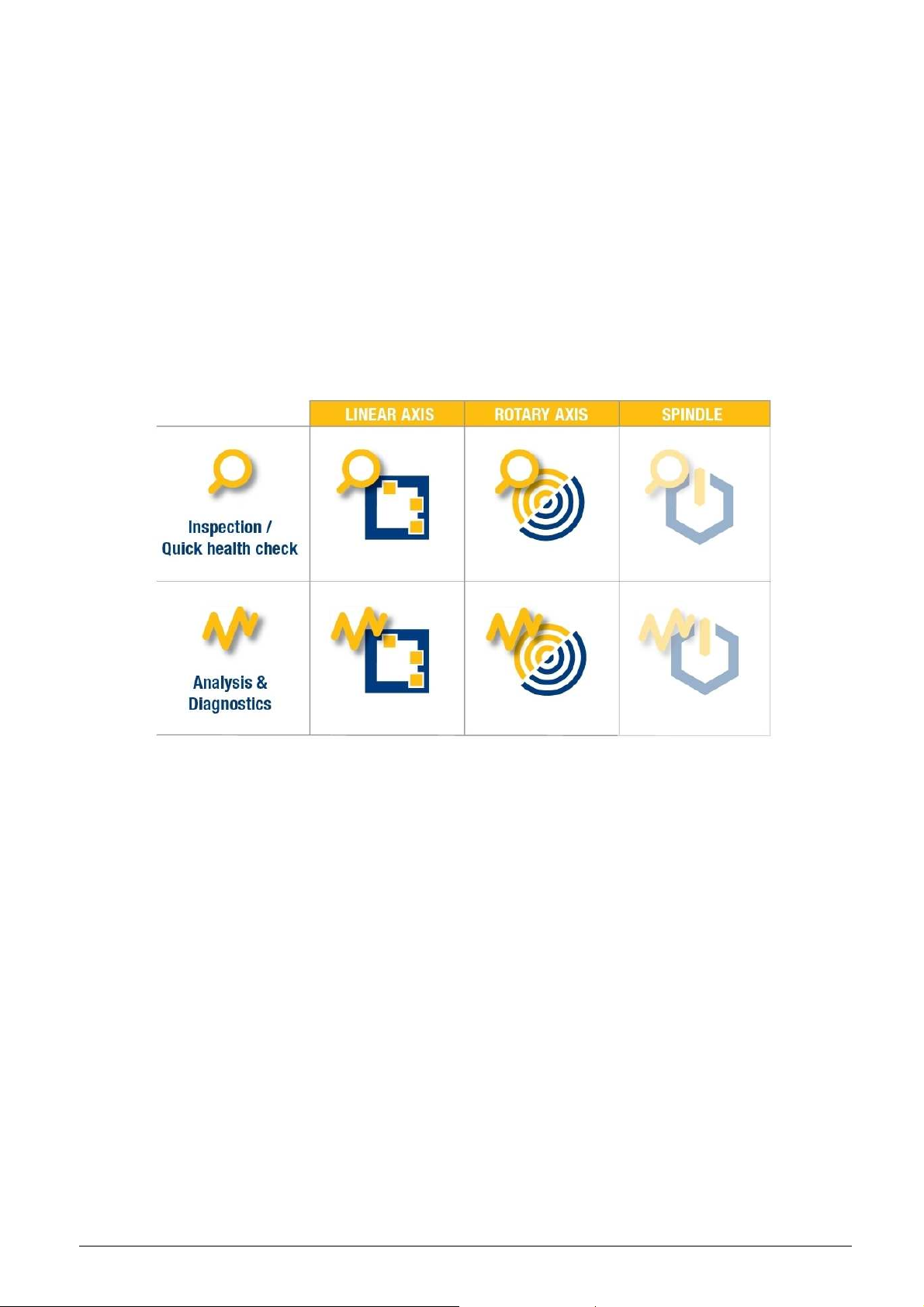
INSPECTOR systems are typically used for production monitoring. Machine-integrated and
workshop robust, they provide rapid qualification of cutting position, rotary table characteristics or
spindle behaviour. Simple go/no-go testing supports machine management and reduces out-oftolerance products; data logging makes essential maintenance planning easy.
ANALYZER systems are typically for advanced users; such as machine tool builders, developers or
maintenance providers. They offer fully calibrated, in-depth measurement and feedback capability.
Machine acceptance, qualification, compensation, alignment and diagnostics are common
applications.
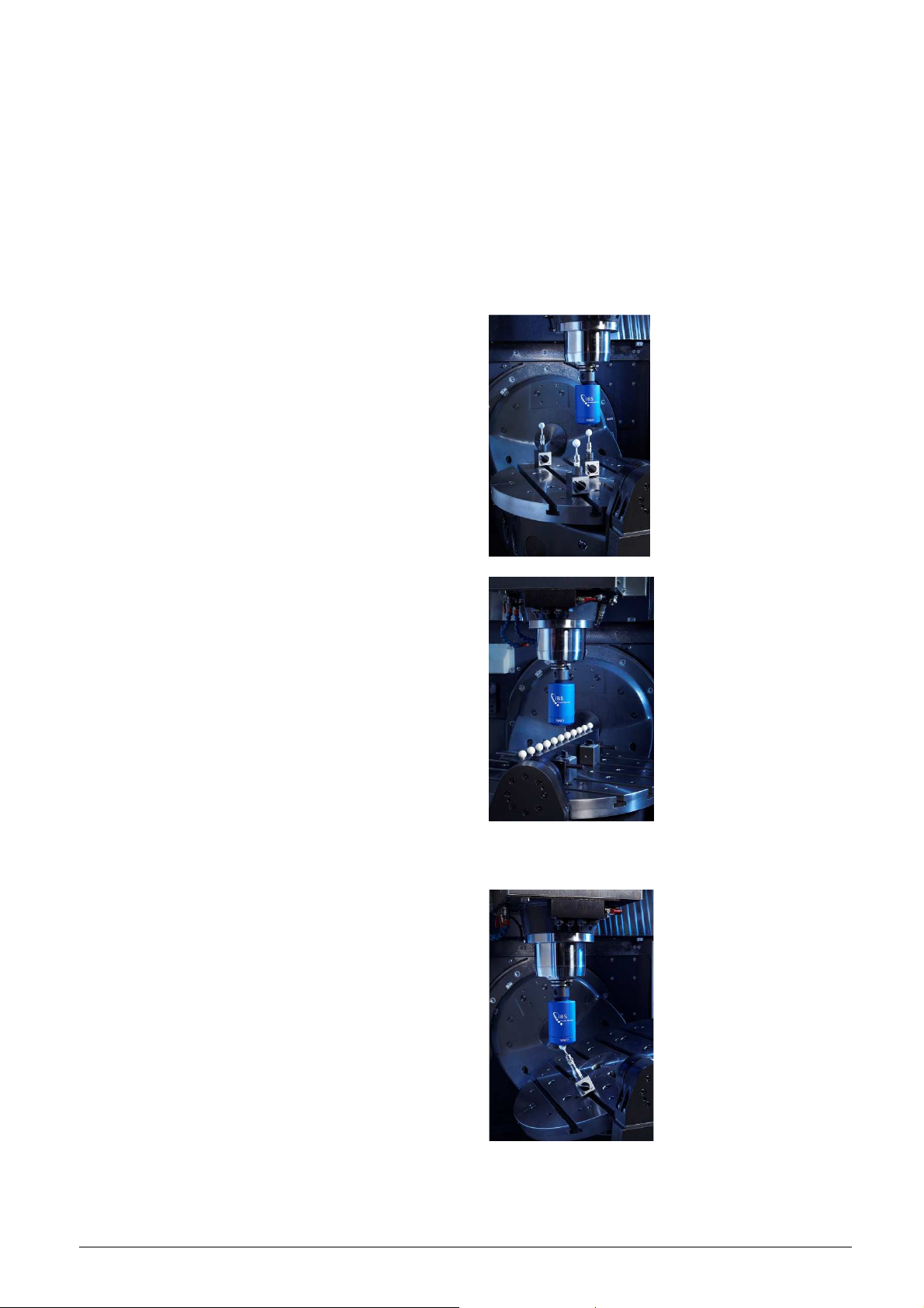
Brief description:
The Position Inspector combines the Trinity
probe with a set of separate master balls.
These master balls are mounted or even
fixed permanently to the machine’s table. The
position of these master balls is measured
periodically (i.e. each hour) and the
measured ball position is compared to the
initial ball position. In this way the long term
stability of a machine tool is monitored
throughout its entire working volume.
The Position Analyzer combines the Trinity
probe with a CMM calibrated ball beam. This
ball beam is mounted parallel to a linear
machine axis and the position of these balls
is measured according to ISO 230-2. By
comparing the measured ball positions with
the calibrated ball positions three error
motions of the linear axis are measured
simultaneously in about 5-10 minutes:
1. Linearity
2. Vertical straightness
3. Horizontal straightness
This application can be considered as 3
classic laser interferometer measurements
combined.
The Rotary Inspector uses the Trinity probe
in combination with a single master ball. The
displacement of the master ball is measured
while the machine executes a predefined
cycle with at least one rotary axis active. This
application is of interest to check the
accuracy of five-axis machine tools with a
high degree of automation. Measurements
described in ISO 10791-6 are implemented
and used typically. A machine and
measurement type data base is used to
measure many machines with little effort.
IBS Precision Engineering
Machine Tool Console
Page 6 of 77
Page 7

The Rotary Analyzer also combines the
Trinity probe with a single master ball but is
typically used by high level machine operator
and machine experts. Measurements can be
generated and analyzed with a high degree
of flexibility. Many options are implemented
to be able to measure any five-axis machine
tool. Often the pivot line of a rotary axis
requires correction which are calculated and
entered into the machine’s controller.
Squareness errors of a rotary axis for
example are determined with the Rotary
Analyzer only.
IBS Precision Engineering
Machine Tool Console
Page 7 of 77
Page 8

2 Software Installation
System requirements:
Operating system : Windows 7, 32 & 64 bit; Windows 8.1, 64 bit
Memory : 4 GB or more
Hard disk : 180GB or more
USB ports : 1 free port for wireless network adapter.
The software comes in one single installer which installs all parts of the system sequentially. The
sequence consists of the following items:
2.1. The “Machine Tool Database”. This database contains all settings- and configuration
parameters used by the “Machine Tool Console” and all applications which, in turn, are
called by this Console. This database is explained in detail in appendix A.
2.2. The “Machine Tool Console”. This Console is used to select from available applications
listed in 2.3. It will also setup the wireless network.
2.3. Any of the following applications:
• Position Inspector;
• Rotary Inspector;
• Position Analyzer;
• Position Analyzer;
2.4. Installer for the “NetGear A6100” network adapter driver for USB. This network adapter
is used to communicate with the measuring head.
2.5. Batch file running a windows registry correction in case the software operates in a
windows ‘.local’ domain.
In the following sections the installation is described in detail.
Note: Make sure you have administrative rights to perform the software installation.
The installation of the ‘Trinity’ measuring head (Trinity) and its calibration must be performed after
the Machine Tool Console and its database are installed. The description of this installation is
described in section 2.4.
2.1 New installation or upgrade
When installed for the first time, the system will install the database in
“C:\IBSPrecisionEngineering\MachineToolDataBase”. The installer takes care of setting the read
and write permissions for all users in this location.
Upgrading the Machine Tool Console from all previous versions to version 2.1.0 has only
consequences for the location of the database. In the old configuration, the location of the
database is in “C:\Program Files (x86)\IBS Precision Engineering\MachineToolDataBase”. The
upgrade will not affect the existing database in any way. Both databases are identical. After the
upgrade has been performed, the system will still point to the database in the “old” location which
will function perfectly with respect to older datafiles.
Page 9

2.2 Start of the installation
Running IBS_Start.exe on the application DVD which comes with the system starts the installation.
The following screen appears (Figure 2-1 shows the installer for the Rotary Analyzer):
Figure 2-1: Installation startup
Click “Next”; the following screen appears:
Figure 2-2: Ready to install
IBS Precision Engineering
Machine Tool Console
Page 9 of 77
Page 10
Clicking “Install” will copy the contents of the DVD to a local directory: “C:\MT_Install_xx” (where
xx is an abbreviation of the application to be installed, for instance xx = PI = Position Inspector):
Figure 2-3: Copy DVD contents to a local directory
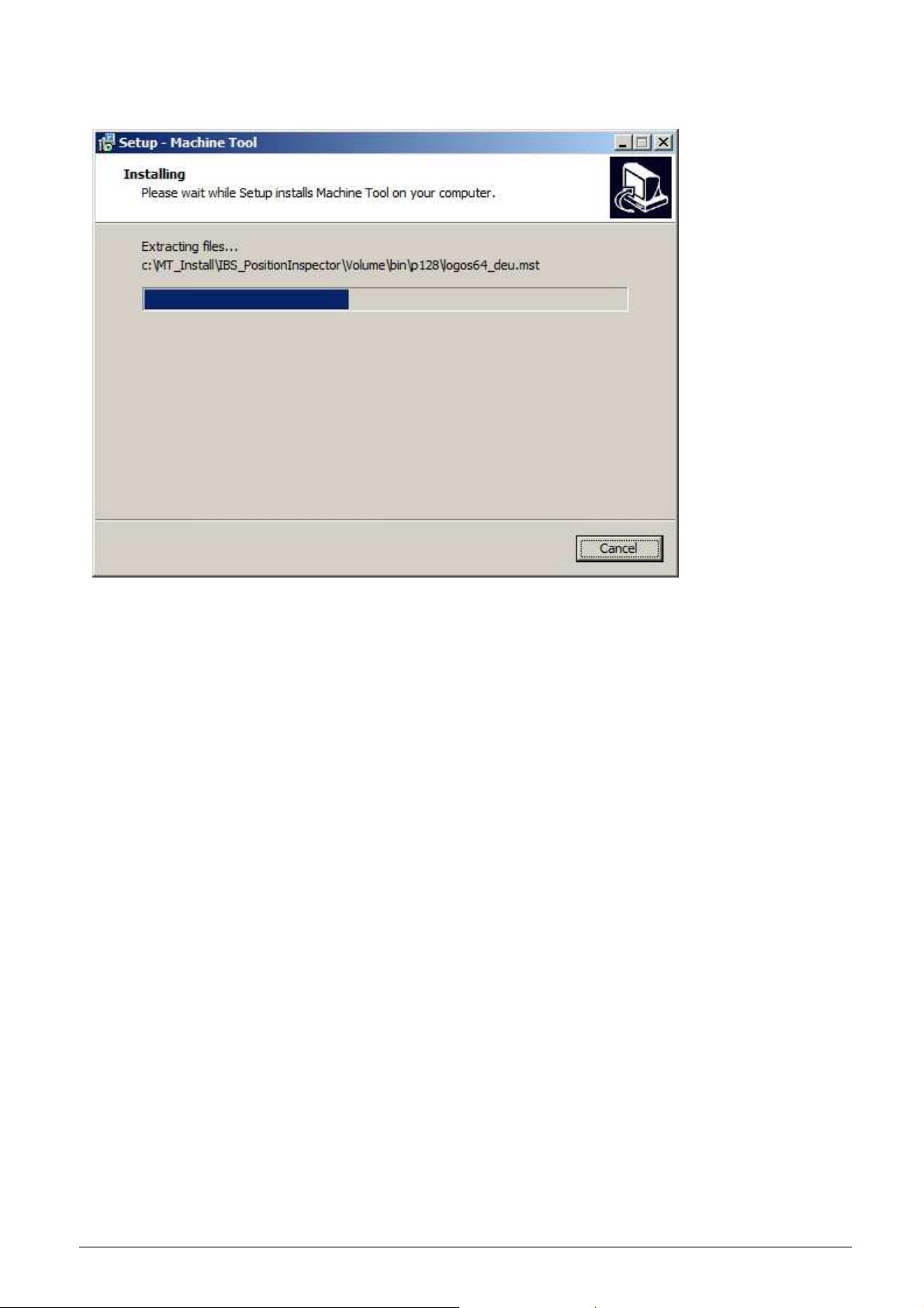
When copying the data to the local directory is finished, the installation of the complete package
will start in ‘silent’ mode, which means that all parts of the software will be installed without any
interaction of the user/operator.
The order of installation is:
1) Machine Tool Database
2) Machine Tool Console
3) Machine Tool Application (Position Inspector, Rotary Inspector, Position Analyzer or
Rotary Analyzer)
4) Windows driver NetGear A6100 USB Network Adapter.
5) Adobe Acrobat PDF Reader
6) Local network domain check
IBS Precision Engineering
Machine Tool Console
Page 10 of 77
Page 11
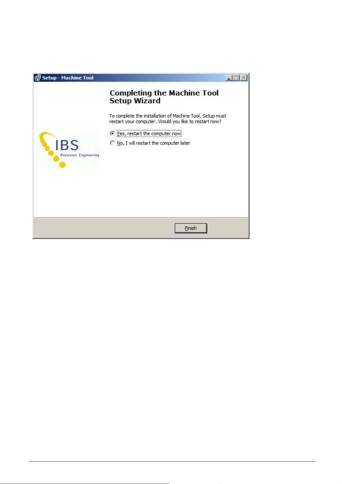
2.3 Finalizing the installation
After installing all parts of the software, the final screen appears:
Figure 2-4: Finish installation with a system restart.
Select “Yes, restart the computer now” and click ‘Finish’ to finish the installation. After restart the
‘Machine Tool Console’ is ready for use.
IBS Precision Engineering
Machine Tool Console
Page 11 of 77
Page 12

2.4 Installation of the ‘Trinity’ measuring head and its calibration
To install a new ‘Trinity’ measuring head (Trinity) and its calibration, the Machine Tool Console and
its database must be installed first.
Insert the DVD containing the Trinity calibration installer into the drive and run ‘Setup.bat’: this will
open a command prompt and the automatic installer. Both windows will disappear when the
installation of the new measuring head calibration is finished.
Figure 2-5 Installing new head calibration
IBS Precision Engineering
Machine Tool Console
Page 12 of 77
Page 13

3 Getting started
3.1 System setup
To startup the wireless network and Trinity the following steps are required:
Step 1: Before using the white D-Link Access Point Adapter, check the switch on the top (located
in the red circle in Figure 3-1) is set to ‘Router AP’. Insert the Access Point Adapter into a
power socket. Wait until its LED turns from red to green (this can last half to one minute);
Figure 3-1: D-Link Access Point Adapter.
Step 2: Insert the NetGear A6100 USB Network Adapter in the laptop;
Figure 3-2 NetGear USB Network Adapter
Note:
install the appropriate driver associated with it and will assign a unique name to this adapter
(“Wireless Connection x”, where x is representing a number). It is required to rename the adapter
to a name without spaces. A correct name would be ‘TrinityAdapter’ or ‘TrinityAdapter1’.
Step 3: Switch on the measuring head;
Figure 3-3: Location of Trinity measuring head switch.
When the NetGear USB Network Adapter is connected for the first time Windows will
IBS Precision Engineering
Machine Tool Console
Page 13 of 77
Page 14

Step 4: For convenience it is recommended to create a shortcut to the IBS_Console.exe
application on the desktop. The icon of the shortcut is shown in Figure 3-4.
Start the application from this shortcut.
Figure 3-4: Console startup icon.
IBS Precision Engineering
Machine Tool Console
Page 14 of 77
Page 15
3.2 First startup of the application
At first startup of the application the following settings may have to be made:
• Set the absolute path to the machine tool database used by the Console and the
inspector/analyzer applications.
• Add the Console application as a rule to the windows firewall (even if this firewall is not
used).
The above mentioned settings are stored in the Console application.
Below the issues are explained in detail:
3.2.1 Absolute path to the machine tool database
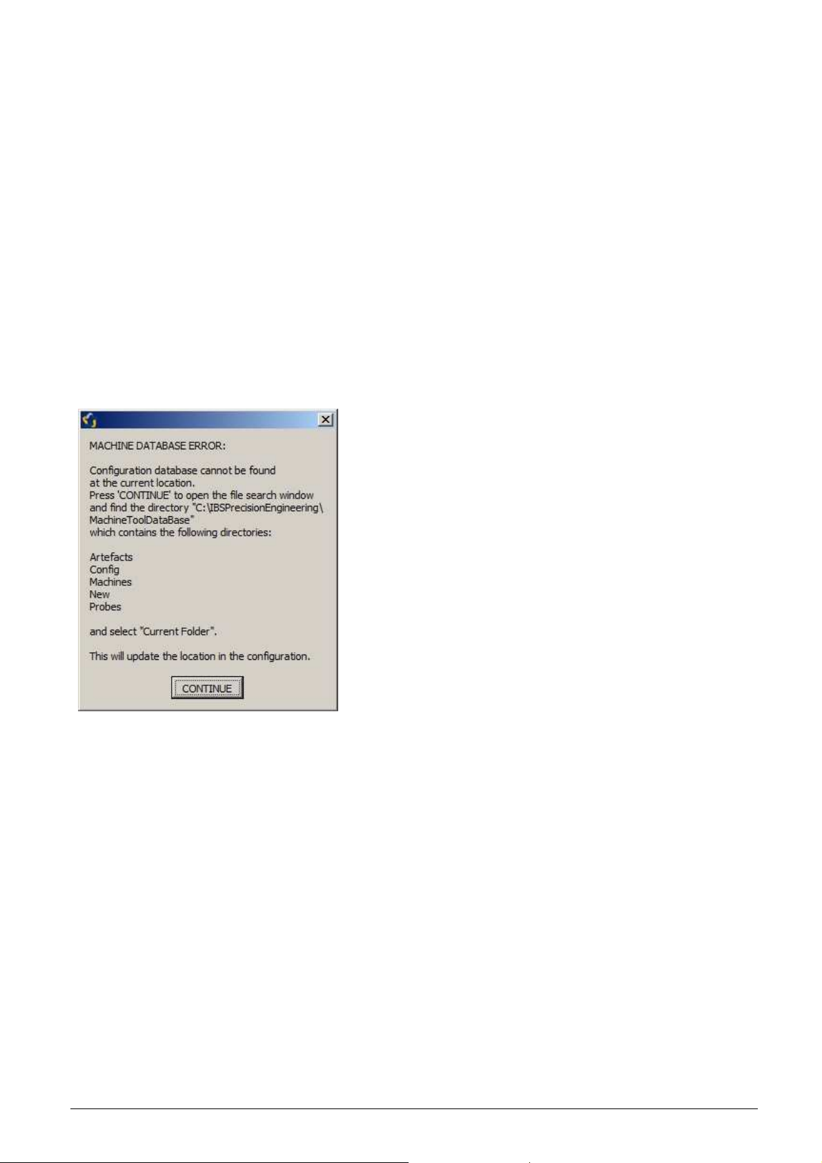
If the path to the machine tool database is not correct at start up the following screen appears:
Figure 3-5: Setup correct path to database.
The application searches for the five directories: Artefacts, Config, Machines, New and Probes,
which are contained in the database. To set the path to this database correctly, select
‘CONTINUE’.
IBS Precision Engineering
Machine Tool Console
Page 15 of 77
Page 16
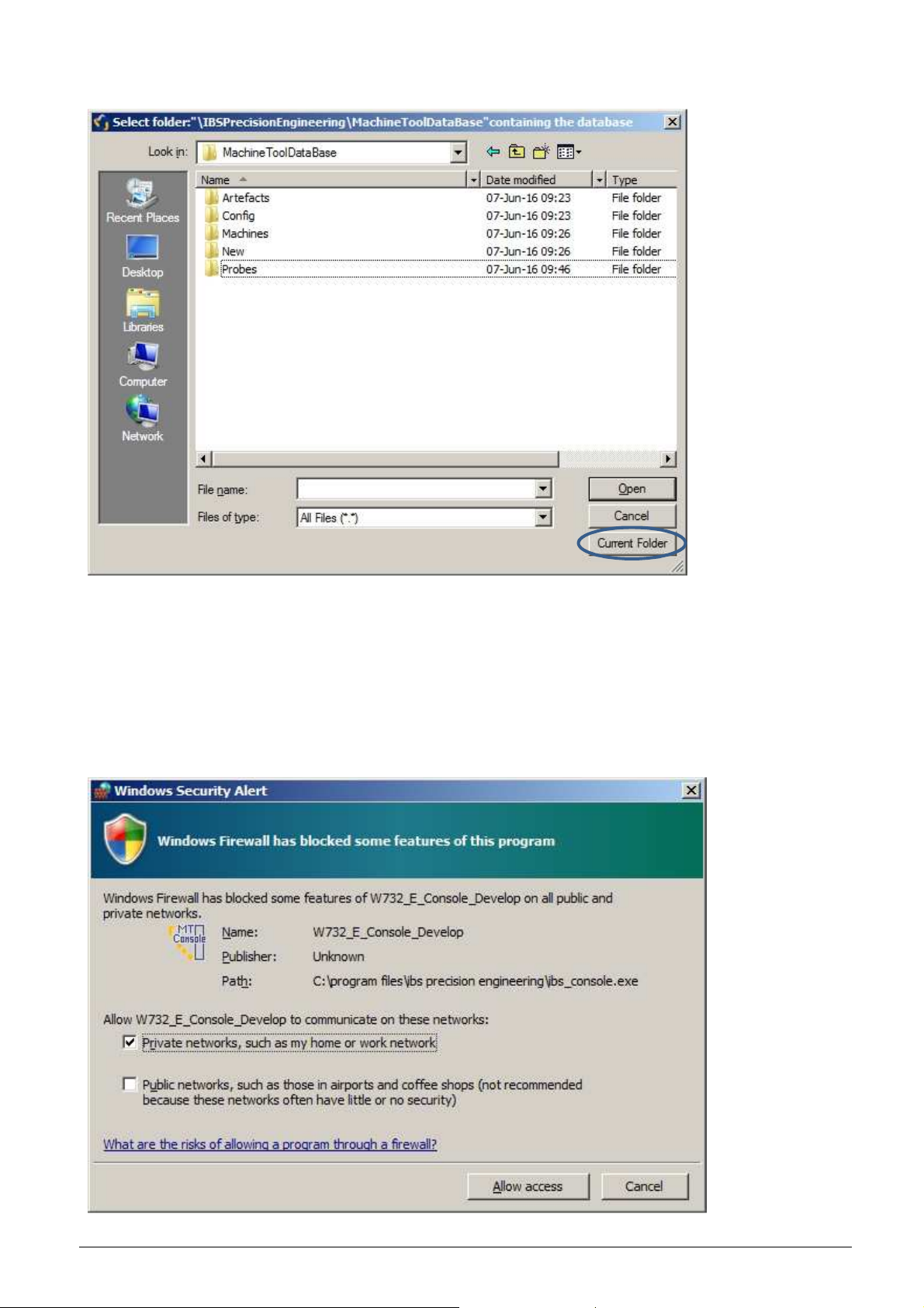
The following file search window appears:
Figure 3-6: Finding the ‘Machine Tool Database’.
When the location of these five directories is found and selected , press ‘Current Folder’. This path
is updated into the system configuration.
3.2.2 Add the Console application as a rule to the windows firewall
When the Console application sets up a wireless connection, the following screen may pop up:
Figure 3-7: Adding the Console application to the windows firewall.
IBS Precision Engineering
Machine Tool Console
Page 16 of 77
Page 17

Selecting ‘Allow access’ adds the application to the windows firewall and updates this information
in the windows configuration permanently.
At next startup of the ‘Machine Tool Console’ these issues do not appear again.
IBS Precision Engineering
Machine Tool Console
Page 17 of 77
Page 18
4 Application
4.1 Startup
Each of the four Machine Tool applications can be individually purchased. Only those installed are
activated in the Machine Tool Console. From this control application a start screen displays a
matrix from which the activated application(s) can be selected:
• Position Inspector;
• Rotary Inspector;
• Position Analyzer;
• Rotary Analyzer.
The ‘Spindle’ applications are not described in this manual.
Figure 4-1: Machine Tool Console.
Each of these four applications, if available, can be selected from this Console. Each selection
opens the “Application Settings & Network Setup” program in order to make the necessary and/or
desired setup for the selected application to follow. This program controls the following features:
• Check whether the application is to be run “as administrator” in windows 7;
• Check whether the application is added to the windows firewall;
• Copy machines or edit existing machines;
• Copy measurement types or edit existing measurement types;
• Setup and connect to Trinity;
• Open the selected application (PI, RI, PA or RA);
• Exit without opening the selected application.
Each item is described in detail in the following sections.
All machine and measurement type settings for each application are held in a central database
which is controlled by the Console software. Here machines, measurement types, measuring
heads and network adapters are stored to be selected as desired.
The selections are saved in one windows configuration file: ‘ConsoleConfig.ini’. This file is read
from and written to by the Console software, and ONLY read by the selected application at start
up.
A description of how to use the database is described in section 5; the layout of the database and
the connecting configuration file is described in appendix A.
IBS Precision Engineering
Machine Tool Console
Page 18 of 77
Page 19

4.2 Application settings & network setup
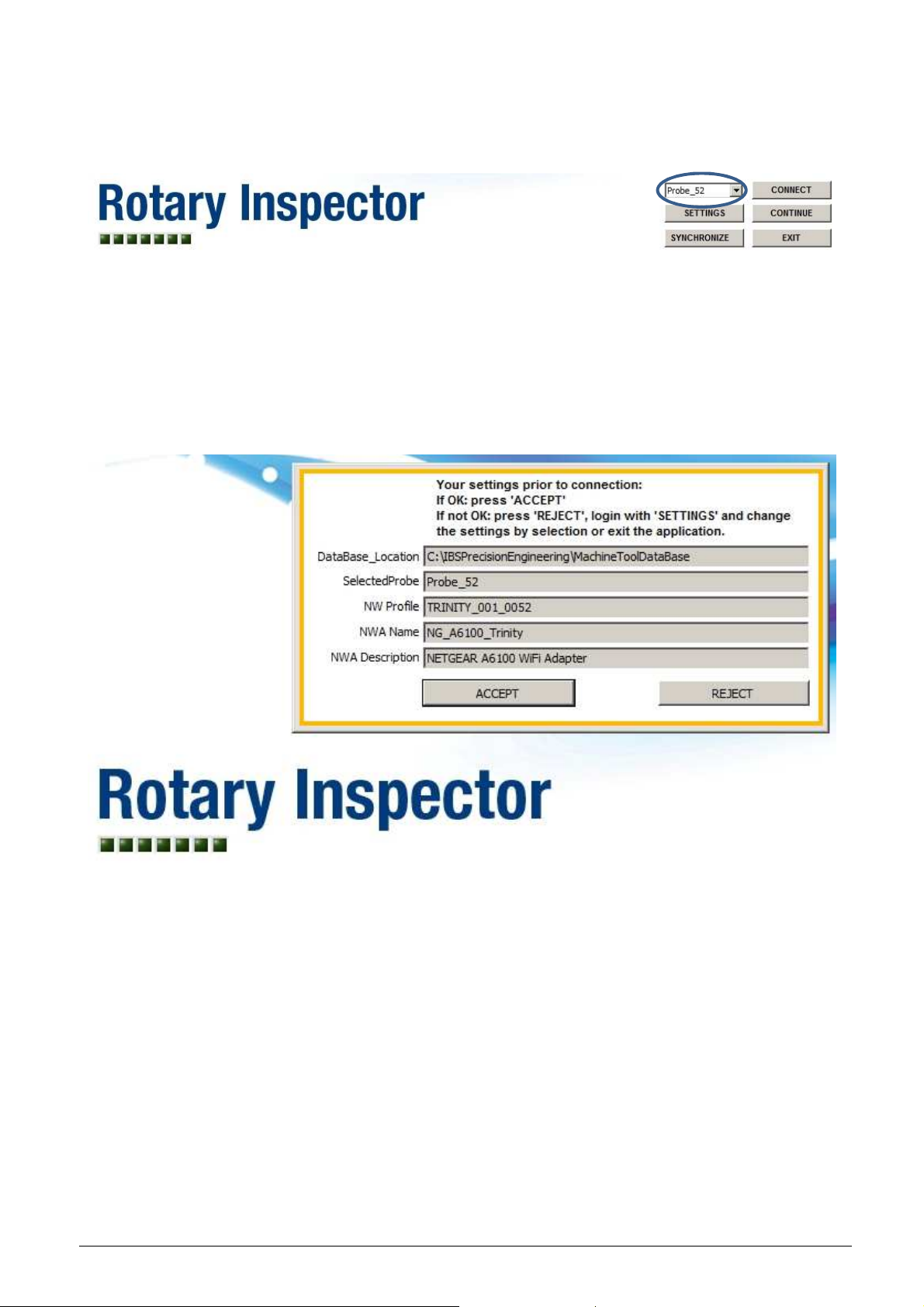
When one of the four main applications is selected (by pressing the appropriate icon), the
“APPLICATION SETTINGS & NETWORK SETUP” program is started and appears with the
following screen (in this case the ‘Rotary Inspector’ is selected):
Figure 4-2 Start screen
The selection field and buttons on the lower right corner of the screen have the following functions:
Probe selection field Here, the probe to be used can be selected without the need of logging
in into the settings (see section 4.2.1).
CONNECT This will setup and start the wireless connection between the application
and the probe (see section 4.2.2).
SETTINGS After logging in into this section, the settings of the wireless connection
can be changed (see section 4.2.3):
1. Select network adapter
2. Select probe
3. Machines can be added, edited or removed from the local
database
4. Rotary Inspector only: local machines can be linked to machines
in a global database when using the “Rotary Inspector Data
Manager”
CONTINUE When the wireless connection is established the selected application will
start, while this “APPLICATION SETTINGS & NETWORK SETUP”
application will be shut down.
SYNCHRONIZE Rotary Inspector only: this button will only appear when the “Rotary
Inspector” is selected AND the Rotary Inspector Data Manager is in use.
Pressing this button will synchronize history data, settings and
measurement results in PDF format with linked machines in the global
database. The Rotary Inspector Data Manager functions are described
in section 6.
EXIT Exits this application returns control to the screen shown in Figure 4-1.
IBS Precision Engineering
Machine Tool Console
Page 19 of 77
Page 20
4.2.1 The “Probe Selection” field
Figure 4-3 Select a probe
Another probe can be selected immediately from the pull down field without logging in into the
‘Settings’ section.
4.2.2 “CONNECT” button
Pressing the “CONNECT” button will show the settings popup screen prior to connection (Fig. 4-4):
Figure 4-4 Settings prior to connection
If the settings are correct, press “ACCEPT” and the network will be setup and the Trinity
connection will be established. See fig. 4-8.
The program automatically checks the status of the selected application and sets up the wireless
network. The progress of this automatic setup is monitored using seven LED’s which turn to green
(success) or red (fail):
The first two LED’s represent the check on the application for the following settings:
1. Setting of the “Run as administrator” option in windows;
2. Setting of the application to be allowed to run in the windows firewall.
The next five LED’s show the entire setup of the wireless network:
3. Load configuration settings of the wireless probe;
4. Setting the correct static IP address on the network adapter;
5. Load wireless network profile into windows;
IBS Precision Engineering
Machine Tool Console
Page 20 of 77
Page 21
6. Connect computer through the access point to the wireless probe;
7. Check connection and start data streaming.
When all LED’s turn to green, the application and wireless network are setup correctly.
If any one of these actions fail, the corresponding LED turns red and the startup sequence is
aborted, asking the user to login (press ‘SETTINGS’) and correct the problem. A description of the
problem is displayed on screen.
If the settings are not correct, i.e. another network adapter and/or probe needs to be selected,
press “REJECT” and login into the settings section by pressing the “SETTINGS” button.
4.2.3 “SETTINGS” button
When another network adapter (NWA) needs to be selected, press “SETTINGS” to login into the
settings section and change the selection of the network adapter. The following login screen will
appear:
Figure 4-5 Login
After entering the password (see Appendix C) and ‘Enter’ on the keyboard or ‘OK’ on the screen,
the “SETTINGS” section appears which is divided into four blocks:
Figure 4-6 Settings screen
IBS Precision Engineering
Machine Tool Console
Page 21 of 77
Page 22

In the block at the upper right corner the correct probe and wireless network adapter can be
selected. Note that two wireless network adapters are shown in the list.
Normally, the USB type network adapter (NetGear) which comes with the system is used for this
purpose. It is also possible to select the internal network adapter if one is available. For this
selection it is mandatory to login into the “SETTINGS” section.
Very important note when using the internal network adapter: this adapter is usually setup to work
with a company’s internal wireless network which issues IP-addresses automatically. This
application changes this setting to a fixed IP-address in a specific address range to work with the
‘Trinity’ system which will disconnect the internal network adapter from the company’s wireless
network. It is therefore NOT recommended to use the internal network adapter with the ‘Trinity’
system.
After selecting the proper network adapter and/or probe, the “SETTINGS” section can be closed in
two ways using the buttons in the lower right block:
1. Pressing “RECONNECT”, which will immediately close the “SETTINGS” section and shows
the connection settings as shown in Figure 4-4 from where the connection can be set up.
2. Pressing “EXIT”, which will also close the “SETTINGS” section and will return control to the
previous screen (Figure 4-2).
Both left blocks on the “SETTINGS” section are database related and will be described in section
5: “Database”.
Pressing “ACCEPT” on the network settings popup screen shown in Figure 4-4; the wireless
network will be set up as described in section 4.2.2.
4.2.3.1 Change the password
In this lower right block it is also possible to change the password used to enter the “SETTINGS”
section. Press the button “CHANGE PASSWORD”; the following screen appears:
Figure 4-7 Change password
This password is set initially during installation to “welcome”. It can be changed here by entering
“welcome” as the old password and the new password in the next two fields. The entries must be 7
characters wide.
Additional note: this password will also be used in the applications.
IBS Precision Engineering
Machine Tool Console
Page 22 of 77
Page 23

4.2.4 “CONTINUE” button
When the wireless connection is set up properly, all LED’s on the starting screen will light up green
meaning that the wireless network is properly setup and functioning, see Figure 4-8:
Figure 4-8: Application Setting & Network Setup.
Pressing the “CONTINUE” button hides the Console program and starts the selected application.
This can be done in two modes:
1. All LED’s have turned green as described above: the selected application is started with full
functionality regarding the wireless Trinity system;
2. The setup procedure was aborted (one red LED): the selected application is started without
the functionality of Trinity. In this case only the analysis functionality of the selected
application (if any) is available.
4.2.5 “SYNCHRONIZE” button
This button only appears when the “Rotary Inspector” application is selected on the startup screen
shown in Fig. 4-1.
The function of this button is explained in section 6 where the use of the “Rotary Inspector Data
Manager” is described.
4.2.6 “EXIT” button
Pressing the “EXIT” button closes this program and returns control to the Console matrix (see
Figure 4-1) where another application can be selected or the Console can be terminated.
IBS Precision Engineering
Machine Tool Console
Page 23 of 77
Page 24

4.3 NC code
With all four Machine Tool applications measurements can be performed for which an NC code is
required. The NC code descriptions can be found in the relevant user manual of each application.
IBS Precision Engineering
Machine Tool Console
Page 24 of 77
Page 25

5 Database
Action
Result
The local database holds the setup, configuration parameters and measurement data performed
by inspector packages.
The layout of the database is explained in Appendix A.
5.1 Opening the database for editing
Pressing the ‘SETTINGS’ button and logging in as shown in Figure 4-5, the ‘Settings’ section will
appear as shown in Figure 5-1:
Figure 5-1 Settings & Database settings
The two blocks on the right side are described in section 4.2: Application settings & network setup.
The lower left block is only relevant when the ‘Rotary Inspector’ application is used in conjunction
with the ‘Rotary Inspector Data Manager’. This combination is described in chapter 6: ‘Rotary
Inspector and RI Data Manager’.
The upper left block is used to add, edit or remove items from the local database:
Machines:
CREATE LOCAL MACHINE Creates a new machine, see section 5.1.1
EDIT LOCAL MACHINE Edit an existing machine (if applicable), see
section 5.1.2
REMOVE/DELETE LOCAL MACHINE Remove or delete an existing machine, see
section 5.1.3
IBS Precision Engineering
Machine Tool Console
Page 25 of 77
Page 26

5.1.1 Create Local Machine
Pressing the ‘CREATE LOCAL MACHINE’ button shows the following screen:
Figure 5-2 Create Local Machine
In the upper left corner a new machine type can be selected from the pull-down list. This list
contains 16 predefined machine types (see Fig. 5-3). The item names are explained in appendix H:
Machine types explained.
Figure 5-3 Select Machine Type
IBS Precision Engineering
Machine Tool Console
Page 26 of 77
Page 27

Once a machine type is selected, a picture is shown in the frame underneath the pulldown list (see
Figure 5-4:
Figure 5-4 Local Machine Type selected
Next, a name must be assigned to the machine. Pressing ‘CREATE MACHINE’ creates the
machine in the database structure and disables the controls on the left side the screen to prevent
multiple inputs which is not possible (see Figure 5-5):
Figure 5-5 New Local Machine created
When creating a new machine, the measurement types associated with the application are created
in a pre-defined way in the appropriate directories.
Press ‘EXIT’ to return control to the ‘Settings’ section.
IBS Precision Engineering
Machine Tool Console
Page 27 of 77
Page 28

5.1.2 Edit Local Machine
This option is only relevant for both the ‘Position Inspector’ and ‘Rotary Inspector’, see section 5.2.
When the ‘EDIT LOCAL MACHINE’ button is pressed with the one of the analyzer applications, the
following screen appears:
Figure 5-6 Edit Local Machine for analyzer applications
All parameter settings for the analyzer applications can be edited using the applications
themselves. Press ‘EXIT’ to return control to the ‘SETTINGS’ section.
5.1.3 Remove or delete a Local Machine
Pressing ‘REMOVE/DELETE LOCAL MACHINE’ shows the following popup:
Figure 5-7: Remove/rename Local Machine
Pressing ‘REMOVE FROM LIST’ only removes the machine from the list so it cannot be selected; it
is NOT removed from the database.
Pressing ‘DELETE’ removes the machine entirely from the database, including all measurement
results from that machine.
Pressing ‘CANCEL’ aborts this operation.
IBS Precision Engineering
Machine Tool Console
Page 28 of 77
Page 29

5.2 Parameter settings
Paramete
r name
Explanation
parameter before a measurement
In this section the parameter settings for each of the inspector applications are explained. These
parameters can also be set during the creation of a local machine.
5.2.1 Parameter setting for “Position Inspector”
When ‘EDIT LOCAL MACHINE’ is pressed as described in section 5.1.2, a machine is selected
and ‘EDIT MACHINE’ is pressed, the following screen appears for the Position Inspector:
Figure 5-8 Parameters for Position Inspector
• Machine parameters for “Position Inspector”
• Measurement type parameters for “Position Inspector”
Time to wait (After Vibration) [s] When the vibration level criterion is met after
positioning the measuring head on the artefact
ball, the system waits the amount of seconds
set with this
point is taken.
Trigger Level [V] Measurement of the vibration level criterion is
triggered when all three sensors of the
measuring head measure below the voltage set
with this parameter.
Vibration Level [µm] When the measuring head is positioned on the
artefact ball, the residual system vibration may
not exceed the value set with this parameter.
Deviation Tolerance X-axis [µm] With this parameter the maximum deviation
with respect to the reference run results is set
for the X-axis. See Figure 5-9.
Deviation Tolerance Y-axis [µm] With this parameter the maximum deviation
with respect to the reference run results is set
for the Y-axis. See Figure 5-9.
Deviation Tolerance Z-axis [µm] With this parameter the maximum deviation
with respect to the reference run results is set
for the Z-axis. See Figure 5-9.
IBS Precision Engineering
Machine Tool Console
Page 29 of 77
Page 30

Figure 5-9 Explanation deviation tolerance.
Deviation tolerance dx, dy. R shows the reference run position, M the measured position. Left X
and Y in tolerance, middle X in and Y out tolerance, right X and Y both out of tolerance.
Press ‘SAVE’ to save the values in the database.
Press ‘EXIT’ to return control to the ‘SETTINGS’ section.
IBS Precision Engineering
Machine Tool Console
Page 30 of 77
Page 31

5.2.2 Parameter setting for “Rotary Inspector”
Parameter name
Explanation
ement
When ‘EDIT LOCAL MACHINE’ is pressed as described in section 5.1.2, a machine is selected
and ‘EDIT MACHINE’ is pressed, the following screen appears for the Rotary Inspector:
Figure 5-10 Parameters for Rotary Inspector
Time to wait (After Vibration) [s] When the vibration level criterion is met after
positioning the measuring head on the artefact
ball, the system waits the amount of seconds
set with this parameter before a measur
point is taken.
Trigger Level [V] Measurement of the vibration level criterion is
triggered when all three sensors of the
measuring head measure below the voltage set
with this parameter.
Vibration Level [µm] When the measuring head is positioned on the
artefact ball, the residual system vibration may
not exceed the value set with this parameter.
Q Tolerance green [mm] This level represents the lower limit of the Q-
value, the meaning of this value is explained in
the Rotary Inspector user manual section 3.1.
Q Tolerance red [mm] This level represents the upper limit of the Q-
value, the meaning of this value is explained in
the Rotary Inspector user manual section 3.1.
Note that when the Rotary Inspector is used in conjunction with the Rotary Inspector Data
Manager, both Q tolerance values are overwritten by the values saved for this machine in the
global database when:
1. The local machine is linked to a machine in the global database
2. Both machines are synchronized
Synchronization will be explained in section 6.
Press ‘SAVE’ to save the values in the database.
Press ‘EXIT’ to return control to the ‘SETTINGS’ section.
IBS Precision Engineering
Machine Tool Console
Page 31 of 77
Page 32

6 Rotary Inspector and RI Data Manager
When multiple machines, which may be situated in more than one location, are measured with the
Rotary Inspector, the system can be extended with the Rotary Inspector Data Manager. This
includes:
1. A global database in which a history of all measurement results and reports are gathered
through synchronization between the global database and one or more local databases
situated on computers/laptops used for measurement with the Rotary Inspector.
2. Several means of presenting and reporting results of one or more machines over time. This
presentation and reporting can be performed for a single machine or a group of machines
which are situated in a specific location by choice. This can be all machines in a plant, a
group of machines located in a single department within a plant or a group of machines
located within a single cell which, in turn, is part of a department. Full description of the RI
Data Manager can be found in the appropriate user manual.
For correct communication between the Console and the RI Data Manager, a wired connection
between the PC/laptop running the Console and the network is required.
Here, the interactions of the Console with the RI Data Manager will be described.
IBS Precision Engineering
Machine Tool Console
Page 32 of 77
Page 33

6.1 Settings
When the Rotary Inspector is selected from the application matrix shown in Fig. 4.1, the
“APPLICATION SETTINGS & NETWORK SETUP” program is started and appears with the screen
shown in Fig. 4.2.
As explained, this is the only application showing the ‘SYNCHRONIZE’ button. Pressing this button
will start the synchronization of all machines which are defined in the local database AND are
linked to a machine in the global database. During the synchronization a little square box on the
button will blink; when finished the square box will disappear.
Figure 6-1 Blinking square box during synchronization
Once the connection between the two databases is established, the global database will be locked
for other local databases until the synchronization is finished.
When another local database (a Console located on another laptop) tries to synchronize with the
global database when it is locked, the following message appears:
Figure 6-2 Global database locked for synchronization
The synchronization consists of three parts:
1. The measurement history in both databases will be synchronized with each other; this
synchronization is executed in both directions which means that all measurement results for
all linked machines are available in both databases.
2. All measurement reports in PDF format will be uploaded to the global database from each
linked machine in the local database.
3. The measurement tolerance settings for the Q-value will be downloaded from the global
database to each linked machine in the local database.
When the synchronization is finished, the global database will be unlocked for access by other
local databases or the RI Data Manager for maintenance purposes.
IBS Precision Engineering
Machine Tool Console
Page 33 of 77
Page 34

6.2 Opening the database for editing
Action
Result
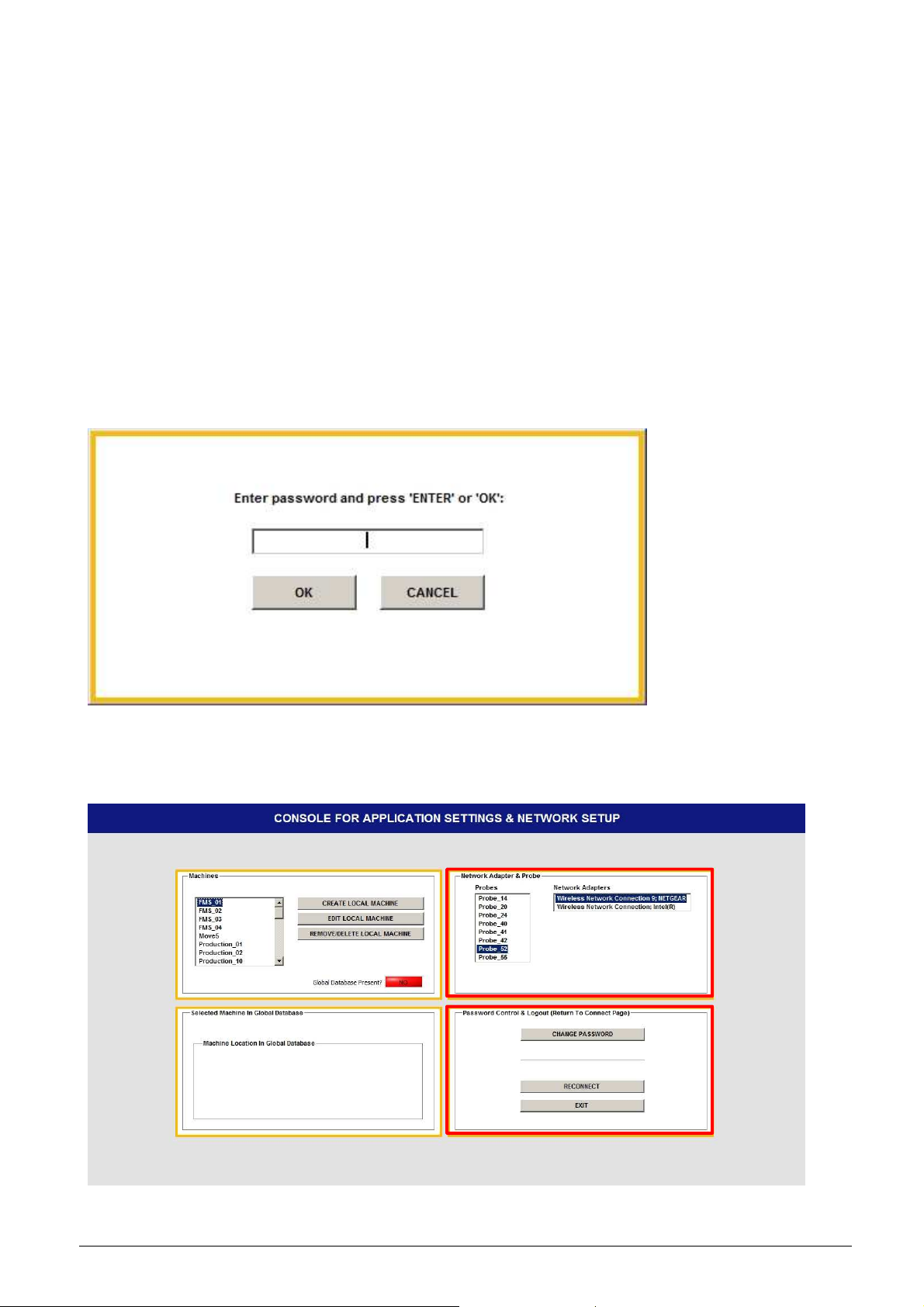
Pressing the ‘SETTINGS’ button and logging in as shown in Figure 4-5, the ‘Settings’ section for
the Rotary Inspector will appear as shown in Figure 6-3:
Figure 6-3 Settings screen for Rotary Inspector
Machines:
LOCATE GLOBAL DATABASE Select the location of the global database
CREATE LOCAL MACHINE Creates a new machine, see also section 5.1.1
EDIT LOCAL MACHINE Edit an existing machine (if applicable), see
section 5.1.2
REMOVE/DELETE LOCAL MACHINE Remove or delete an existing machine, see
section 5.1.3
LINK MACHINE TO GLOBAL DATABASE Link a local machine to a machine located in
the global database
SYNCHRONIZE WITH GLOBAL DATABASE Synchronize a local machine with a linked
machine in the global database
Note that at initial startup the location of the global database is unknown to the Console and needs
to be setup; this is explained in section 6.2.1. This is represented by the red LED stating that the
global database is not present.
IBS Precision Engineering
Machine Tool Console
Page 34 of 77
Page 35

6.2.1 Locate Global Database
The global database and its location is setup by the RI Data Manager and is usually found on a
network drive or mapping marked by a specific drive letter. At initial startup of the Console, the
location of the global database needs to be entered. Once the database is found, the location is
saved in the initialization files of the Console and will be recognized at startup.
Pressing the button ‘LOCATE GLOBAL DATABASE’ opens the following windows screen:
Figure 6-4 Locating the global database
Find the network directory which contains the subdirectory ‘Plants’ and press ‘Current Folder’, the
‘Settings’ section for the Rotary Inspector will re-appear as shown in Figure 6-5:
Figure 6-5 Settings screen for Rotary Inspector with global database present
IBS Precision Engineering
Machine Tool Console
Page 35 of 77
Page 36

Note that the button ‘LOCATE GLOBAL DATABASE’ has disappeared from the screen and that
the ‘LINK’ and ‘SYNCHRONIZE’ buttons are enabled.
When the selected machine in the upper left block is linked to the global database (green LED), the
lower left block shows the link information about the local machine in the global database.
6.2.2 Create Local Machine
Pressing the ‘CREATE LOCAL MACHINE’ button shows the following screen:
Figure 6-6 Create Local Machine
The creation of a new local machine is similar to the procedure described in section 5.1.1. In
conjunction with the global database, a second option for creating a local machine is implemented.
6.2.2.1 Creating a local machine from the global database
When the local machine to be created already exists in the global database and there is no active
link to this machine, it is possible to download this machine and define this as the new local
machine. The advantage of this method is that the new local machine is automatically linked to and
synchronized with the original machine in the global database.
Press the button ‘SELECT MACHINE IN GLOBAL DATABASE’. The following screen pops up:
Figure 6-7 Selecting the machine in the global database
IBS Precision Engineering
Machine Tool Console
Page 36 of 77
Page 37

On the left side of the screen four pull down fields can be used to select the machine to be
downloaded:
1. Select available plant
2. Select available department
3. Select available cell
4. Select available machine (Figure 6-8):
Figure 6-8 Select machine to download
Press ‘RETURN’.
When the selected machine is already linked to a local machine the following warning appears:
Figure 6-9 Machine link already exists
In this case, another machine must be selected. The download procedure is aborted at this point
and returns control to the screen shown in Figure 6-6 where the procedure can be restarted.
IBS Precision Engineering
Machine Tool Console
Page 37 of 77
Page 38

If the download succeeds, the previous screen appears with the new machine selected:
Figure 6-10 Machine selected from global database
The ISO description (in this case S_HS_HT_BC) for the selected machine is explained in
appendix H.
Enter the machine name and press ‘CREATE MACHINE’. The tab on the right side of the screen
will be enabled:
Figure 6-11 Set parameters
Here the parameters can be set for the new machine individually; it must be noted however that
when the machine is synchronized, the Q-tolerance values will be downloaded from the global
database and are set in the local machine: the Q-tolerance values from the global database are
therefore leading over the local database. The parameters can be saved by pressing ‘SAVE’.
Press ‘EXIT’ to return to the ‘Settings’ section.
IBS Precision Engineering
Machine Tool Console
Page 38 of 77
Page 39

6.2.3 Edit local machine
A full description is given in section 5.1.2.
6.2.4 Remove/Delete local machine
A full description is given in section 5.1.3.
6.2.5 Link local machine to global database
To link an existing local machine to an existing global machine, press ‘LINK MACHINE TO
GLOBAL DATABASE’. The following screen will pop up:
Figure 6-12 Linking an existing local machine to an existing global machine
The screen opens with the first machine in the local database; this machine is already linked into
the global database: the link path is shown in the left part of the screen.
Select the local machine to be linked in the pull down field on the upper left side of the screen:
Figure 6-13 Select local machine to be linked
IBS Precision Engineering
Machine Tool Console
Page 39 of 77
Page 40

No link exists for this machine at this point:
Figure 6-14 Select machine in the global database to link local machine to
The list of machines in the right pull down field represents only the machines in the global
database which are not linked to any local machine. When one is selected the location information
including all names is shown in the field on the lower right side of the screen.
Press ‘CREATE LINK’. The Console will check whether the ISO descriptions of both local and
global machine match. If this is not the case, a link will not be created:
Figure 6-15 Machine type mismatch
If both ISO descriptions do match, the link will be created and an automatic synchronization
between both machines will be executed:
Figure 6-16 Machine type match
Press ‘EXIT’ to return to the ‘Settings’ section.
IBS Precision Engineering
Machine Tool Console
Page 40 of 77
Page 41

6.2.6 Synchronize with Global Database
Press the ‘SYNCHRONIZE WITH GLOBAL DATABASE’ button will synchronize only the selected
local machine with its linked global machine.
This option is useful when more than one computer/laptop is used to perform the measurements
with. While each computer has its own copy of the local machine linked to the same machine in the
global database, the measurement history will be shared among these computers through the
synchronization. The measurement reports however, will only be uploaded in the global database
and can be selected from the RI Data Manager only.
IBS Precision Engineering
Machine Tool Console
Page 41 of 77
Page 42

Appendix A Database
A.1 Database
The central database is a structure of directories and files which contain the setup, configuration
parameters and measurement data performed by inspector packages.
Note: For a correct operation of the Console it is not permitted to change, move or delete
(parts of) this structure in any way.
Figure A-1: Database structure
The tree is built up as follows:
The three .ini files contain only the names of the artefacts, machines and Trinity probes
respectively.
IBS Precision Engineering
Machine Tool Console
Page 42 of 77
Page 43

The ‘Machines’ directory contains one directory for each machine which, in turn, contains a
‘Measurements’ directory which is related to the given machine only. The database directory
structure opened looks like:
Figure A-2: Database structure opened
When a new Trinity measuring head or an existing Trinity measuring head calibration is added, the
installer copies this file in the ‘New\NewProbe’ directory. The Console program moves this file to
the appropriate directory along with its configuration settings automatically.
• A new measuring head calibration overwrites the old one in the existing directory.
• The calibration file of a new measuring head is placed into a newly created Trinity probe
directory, leaving older existing Trinity probe directories untouched.
IBS Precision Engineering
Machine Tool Console
Page 43 of 77
Page 44

A.2 ConsoleConfig.ini file
The ‘ConsoleConfig.ini’ file which contains the data which is exchanged between the Console and
the selected application is as follows:
[GENERAL INFO]
DB_Location = "/C/Program Files (x86)/IBS Precision Engineering/MachineToolDataBase"
SelectedProbe = "Probe_34"
SelectedMachine = "LU-620"
SelectedMeasurement = "PI_03_Balls"
SelectedArtefact = "BB_UMTK_1619_june2010"
NW_Adapter = "NETGEAR WNDA3100v2 N600 Wireless Dual Band USB Adapter"
NW_Adapter_GUID = "2614341687_41530_19167_163_200_237_7_27_208_76_79"
NW_Profile = "TRINITY_001_0034"
Xbee_Vs_S6B = 0
Probe_Available = 1
Where:
1. DB_Location is the location of the database directory structure;
2. SelectedProbe is the current wireless ‘Trinity’ measuring head and refers to the directory
name which is, in turn, part of the ‘probes’ directory. In this ‘Probe_xx’ directory a
configuration file is read which contains all network settings for this particular probe;
3. SelectedMachine is the current machine on which measurements will be performed;
4. SelectedMeasurement is the current measurement which will be performed;
5. SelectedArtefact is only used by the ‘Position Analyzer’ and will further be ignored;
6. NW_Adapter is the description of the type name of the used network adapter, this is NOT a
user given name;
7. NW_Adapter_GUID is the ID number of the network adapter which is set in the hardware,
windows uses this number for network adapter identification. The Console software needs
this number in order to be able to call the adapter for signal strength information;
8. NW_Profile is the current network profile the Console software uses to set and load the
network profile in windows;
9. Xbee_Vs_S6B is the version number of the wireless interface inside the wireless probe.
Currently, there are two different types of wireless interfaces for the probe: version ‘S6’ and
the newer version ‘S6B’. The Console software has to determine which version is contained
in the current probe because the command set used to control this interface is different in
both versions;
10. When the wireless probe is available and recognized in the system this value is set to ‘1’
and the applications can work with the wireless probe to perform measurements.
Otherwise, when the probe is not available and/or recognized in the system, the
applications can still be called and used for analytical purposes if available. Obviously,
measurements cannot be performed in this mode and this value is set to ‘0’.
This information is initially read by the Console at startup and shown on the screen as the previous
setting. When all desired selections are made and the application (e.g. Position Inspector) is
started, this data is written to this file BEFORE the application starts.
The application reads this data at startup and the appropriate settings for machine, measurement
and probe are retrieved from the various locations in the database to make an instant correct
measurement possible.
IBS Precision Engineering
Machine Tool Console
Page 44 of 77
Page 45

Appendix B Operation in a ´.local´ domain
Introduction
In some cases the domain is setup as a “.local” network. There is a known compatibility issue with
this domain and a component required by the National Instrument runtime engine, which is
installed by the Console software.
Problem
A subcomponent of NI products may cause unexpected behavior when installed on Windows
machines located on a .local domain.
Two main behaviors have been observed:
• Longer than normal boot times (around 20 minutes);
• Screen blacks out and becomes unresponsive after entering log-on credentials.
Identification
When running the setup program an automatic check for a .local domain is performed. If it is found
a warning is issued. At the end of the installer, a batch file supplied by National Instruments, which
solves this issue, is always executed.
To verify your domain right-click Computer and select Properties from the shortcut menu. Look
under “Computer name, domain, and workgroup settings” and check the “domain”.
If it contains .local the unexpected behavior may occur.
Solution 1
If the unexpected behavior still occurs please run the disable_nsp.bat which can be found on the
setup cd. Make sure to run it as an administrator.
Figure B-1: Running ‘disable_nsp.bat’.
IBS Precision Engineering
Machine Tool Console
Page 45 of 77
Page 46

Solution 2
If the unexpected behavior still occurs after running disable_nsp.bat please do the following:
Start regedit through the windows start menu:
Figure B-2: Start regedit.
Scroll to the following keys:
HKEY_LOCAL_MACHINE\SYSTEM\CurrentControlSet\services\WinSock2\Parameters\Name
Space_Catalog5\Catalog_Entries
IBS Precision Engineering
Machine Tool Console
Page 46 of 77
Page 47

Figure B-3: Contents windows registry.
IBS Precision Engineering
Machine Tool Console
Page 47 of 77
Page 48

Find the key nimdnsNSP. This is usually the last number in the list.
Set the “Enabled” value data to 0.
Figure B-4: Editing windows registry.
If the key Catalog_Entries 64 exists:
HKEY_LOCAL_MACHINE\SYSTEM\CurrentControlSet\services\WinSock2\Parameters\Name
Space_Catalog5\Catalog_Entries64
Then repeat the procedure; Find the key nimdnsNSP, and set the “Enabled” value data to 0.
IBS Precision Engineering
Machine Tool Console
Page 48 of 77
Page 49

Appendix C Password
The password used to log into the ‘Settings’ and the database is by default:
‘welcome’
Without the quotes and is set at installation. This password can/may be changed; for an
explanation see section 4.2.2.
IBS Precision Engineering
Machine Tool Console
Page 49 of 77
Page 50

Appendix D Output definition parameters
Output
Description
Definition
in ISO
x,xyzbc
y,xyzbc
z,xyzbc
D.1 Overview Rotary
D.1.1 Rotary Analyzer (RA)
Tabsheet Processed (the second)
XOC Pivot point correction of C-axis in X direction in mm XOC
YOC Pivot point correction of C-axis in Y direction in mm YOC
AOC Squareness error between C-axis and Y-axis
(C-axis is rotated along X-axis).
Variation in Z of least squares straight line fit in the YZplane in mm
BOC Squareness error between C-axis and X-axis
(C-axis is rotated along Y-axis).
Variation in Z of least squares straight line fit in the XZplane in mm
XOB Pivot point correction of B-axis in X direction in mm XOB
ZOB Pivot point correction of B-axis in Z direction in mm ZOB
AOB Squareness error between B-axis and Z-axis
(B-axis is rotated along the X-axis)
Variation in Y of least squares straight line fit in the YZ –
plane in mm
COB Squareness error between B-axis and X-axis
(B-axis is rotated along the Z-axis)
Variation in Y of least squares straight line fit in the XY –
plane in mm
YOA Pivot point correction of A-axis in Y direction in mm YOA
ZOA Pivot point correction of A-axis in Z direction in mm ZOA
BOA Squareness error between A-axis and Z-axis
(A-axis is rotated along the Y-axis)
Variation in X of least squares straight line fit in the XZ –
plane in mm
COA Squareness error between A-axis and Y-axis
(A-axis is rotated along the Z-axis)
Variation in X of least squares straight line fit in the XY –
plane in mm
Tabsheet Raw (the first)
Sx Measured deviation in X direction in mm S
Sy Measured deviation in Y direction in mm S
Sz Measured deviation in Z direction in mm S
ACT- Minimum XYZ measurement in mm n.a.
ACT+ Maximum XYZ measurement in mm n.a.
Q-value The maximum variation measured (=ACT+ minus ACT-)
AOC
(Radius needed for
squareness angle)
BOC
(Radius needed for
squareness angle)
AOB
(Radius needed for
squareness angle)
COB
(Radius needed for
squareness angle)
BOA
(Radius needed for
squareness angle)
COA
(Radius needed for
squareness angle)
n.a.
IBS Precision Engineering
Machine Tool Console
Page 50 of 77
Page 51

D.1.2 Rotary Inspector (RI)
Output
Description
Definition
in ISO
x
x,xyzbc
y
y,xyzbc
z
z,xyzbc
Output
Description
Definition
in ISO
Output
/ Ball
Desc
ription
Definition
in ISO
Q-value The maximum variation measured (=ACT+ minus ACT-) n.a.
S
S
S
Measured deviation in X direction in mm S
Measured deviation in Y direction in mm S
Measured deviation in Z direction in mm S
XOC Pivot point correction of C-axis in X direction in mm XOC
YOC Pivot point correction of C-axis in Y direction in mm YOC
XOB Pivot point correction of B-axis in X direction in mm XOB
ZOB Pivot point correction of B-axis in Z direction in mm ZOB
YOA Pivot point correction of A-axis in Y direction in mm YOA
ZOA Pivot point correction of A-axis in Z direction in mm ZOA
D.2 Overview Linear
D.2.1 Position Analyzer (PA)
EXX A Linearity; Accuracy X-axis in mm EXX A
EXX B Linearity; Backlash in mm EXX B
EXX E Linearity; Systematic Positional Deviation in mm EXX E
EXX M Linearity; Mean Positional Deviation in mm EXX M
EXX R Linearity; Repeatability of positioning in mm EXX R
EYX Straightness error X-axis in Y direction in mm EYX
EZX Straightness error X-axis in Z direction in mm EZX
EYY A Linearity; Accuracy Y-axis in mm EYY A
EYY B Linearity; Backlash in mm EYY B
EYY E Linearity; Systematic Positional Deviation in mm EYY E
EYY M Linearity; Mean Positional Deviation in mm EYY M
EYY R Linearity; Repeatability of positioning in mm EYY R
EXY Straightness error Y-axis in X direction in mm EXY
EZY Straightness error Y-axis in Z direction in mm EZY
EZZ A Linearity; Accuracy Z-axis in mm EZZ A
EZZ B Linearity; Backlash in mm EZZ B
EZZ E Linearity; Systematic Positional Deviation in mm EZZ E
EZZ M Linearity; Mean Positional Deviation in mm EZZ M
EZZ R Linearity; Repeatability of positioning in mm EZZ R
EXZ Straightness error Z-axis in X direction in mm EXZ
EYZ Straightness error Z-axis in Y direction in mm EYZ
D.2.2 Position Inspector (PI)
Deviation X Deviation in X w.r.t. reference measurement in µm n.a.
Deviation Y Deviation in Y w.r.t. reference measurement in µm n.a.
Deviation Z Deviation in Z w.r.t. reference measurement in µm n.a.
IBS Precision Engineering
Machine Tool Console
Page 51 of 77
Page 52

Appendix E Hardware
The Machine Tool Console measurement system is supplied in a travel case containing, see
Figure :
1. Trinity measuring head;
2. D-Link Access Point (switch in Router/AP position);
3. NetGear Wireless USB Adapter;
4. Four batteries;
5. Battery charger & adapter;
6. Master ball 75mm;
7. Extension rods for Master ball;
8. Tool setter ball with M4 fine thread;
9. Mounting magnet with M8 thread hole;
10. Two Allen keys, size 4 mm.
9
8
1
4
10
5
2
5
3
6
7
Figure E-1: Content of Trinity travel case.
Default this system is supplied with a euro plug. Contact IBS Precision Engineering if another plug
type is required.
Warning: The Trinity measuring head is a precision measurement instrument and should be
treated as such. Handle the Master ball and tool setter ball with great care.
Specifications of the Trinity measuring head system:
Roundness error Master ball: < 0.6 µm
Nominal diameter of Master ball: 22 mm
Length Master ball: 75 mm
Measuring head:
Measurement uncertainty of TP-001: U
< 1.5 µm (full range)
1d
U1d < 1 µm (within 1 mm range)
Measurement range: 3.50 mm
Power consumption (idle/measure/sleep): 1W (21.5 hrs.) / 1.3W (17 hrs.) / 0.52 W (42 hrs.)
IBS Precision Engineering
Machine Tool Console
Page 52 of 77
Page 53

Wireless specifications:
Operating frequency: 2.4 GHz
Standard: 802.11b/g/n
Security: WPA2-PSK (only in access point mode)
Regulatory Approvals of Wireless module: FCC, IC, CE/ETSI, C-TICK, TELEC
Supplied:
• Manual Console software manual(this document);
• Calibration certificate measuring head;
• Application install DVD including the Console software;
• Measuring head calibration file installer DVD;
The Trinity is provided with LEDs on both sides and these have 4 modes of operation:
1. Constantly lit of one of two sides
System is on, but not associated with a wireless network;
2. Slow flashing (1 second interval)
System is on and associated with a wireless network;
3. Flashing (0.2 second interval)
System is on and streaming data;
4. Very slow flashing (2 second interval)
System is asleep.
The red LED lights up when the battery has approximately 1 hour of measurement time remaining.
It is advised to replace the batteries when this LED becomes active.
IBS Precision Engineering
Machine Tool Console
Page 53 of 77
Page 54

Appendix F Troubleshooting
• The Console application is by default set to run as administrator and will be added as a rule
to the windows firewall at first run. If that fails please make sure you are administrator or
have full administrative rights.
• If the Console application is to be run from a standard user account without the necessary
administrative rights, the application must be started using a specific configured shortcut
which takes care of these administrator issues. Detailed instructions how to set up this
shortcut are given in appendix G.
• If your system has an additional firewall (other than windows) please consult the manual of
that firewall to allow access for the software packages. All packages must be allowed to
write and read for UDP and TCP protocols.
IBS Precision Engineering
Machine Tool Console
Page 54 of 77
Page 55

Appendix G Using the application in a standard user account
To be able to run, the Trinity software requires administrative rights. Running the software from a
standard windows user account requires a special shortcut which takes care of these
administrative requirements without prompting for the administrator password.
This specially configured shortcut has to be setup in the built-in administrator account which must
therefore be enabled and set with a password. Creating the shortcut using other defined
administrator accounts will fail.
G.1 Enable built-in administrator account
The built-in administrator account is by default disabled and not password protected in windows
and must therefore be enabled first. A password must also be set. The following description will
show how to check the enabled state and the setting of the password of the administrator account.
Figure G-1 Select Computer Manager
IBS Precision Engineering
Machine Tool Console
Page 55 of 77
Page 56

See figure G-1: click “Start”, right click “Computer” and select “Manage”. In the following screen,
select “Local Users and Groups” and open the “Users” folder. Right click on “Administrator” and
select “Properties” (Fig. G-2):
Figure G-2 Select administrator properties
In the administrator properties make sure the “Account is disabled” option is unchecked (see
figure G-3):
Figure G-3 Enable administrator account
When any changes are made, the “Apply” button becomes active. Press “Apply” (only when active)
and “OK” to return to the screen shown in figure G-2.
IBS Precision Engineering
Machine Tool Console
Page 56 of 77
Page 57

Right click on “Administrator” again and select “Set Password…”, the following message appears:
Figure G-4 Proceed to set password
Click “Proceed” to the following screen:
Figure G-5 Set password
Enter a unique password in both fields and press “OK”. If both fields are filled with an identical
name the following message appears:
Figure G-6 Password set successfully
Press “OK” twice and close the computer management screen.
IBS Precision Engineering
Machine Tool Console
Page 57 of 77
Page 58

G.2 Get the computer name
In order to be able to set the administrator credentials (section G.3) and create the special shortcut
(section G.4), the computer name must be available. If the computer name is unknown, it can be
found in the control panel:
Figure G-7 Select Control Panel
On the control panel, select “System and Security”. In the “System” item select “See the name of
this computer” (Fig. G-8):
Figure G-8 See the name of this computer
On the following screen the computer name can be found (Fig. G-9):
Figure G-9 Computer name
Save the computer name and close the control panel.
IBS Precision Engineering
Machine Tool Console
Page 58 of 77
Page 59

G.3 Set administrator credentials
Back on the desktop press “Start” and select the “Control Panel”:
Figure G-10 Select Control Panel
IBS Precision Engineering
Machine Tool Console
Page 59 of 77
Page 60

The “Control Panel” appears:
Figure G-11 Control Panel
See figure G-11: select “User Accounts and Family Safety” and open the “Credential Manager”:
Figure G-12 Select Credential Manager
IBS Precision Engineering
Machine Tool Console
Page 60 of 77
Page 61

In the “Credential Manager” select “Add a Windows Credential”, the following input fields will
appear:
Figure G-13 Enter credentials
Fill the fields with the information as shown in figure G-13. The ‘Internet or network address’
contains the name of the PC followed by a backslash and “Administrator”, the ‘User name’ is
“Administrator” and the ‘Password’ is the unique password entered in figure G-5 as shown above.
Press “OK” when done.
The entries should look like the screen shown in figure G-14:
Figure G-14 Credentials after entering
Close the “Control Panel”.
IBS Precision Engineering
Machine Tool Console
Page 61 of 77
Page 62

G.5 Creating the special shortcut
Right click on the desktop, select “New” and “Shortcut”:
Figure G-15 Create new shortcut
The following screen appears:
Figure G-16 Enter settings for shortcut
The easiest way to set up this shortcut: Right click on the desktop and select “New” and “Shortcut”.
Use the “Browse…” button to select the ‘IBS_Console.exe’ application. In the location field the full
path and name to the application appears:
“C:\Program Files (x86)\IBS Precision Engineering\IBS_Console.exe”
IBS Precision Engineering
Machine Tool Console
Page 62 of 77
Page 63
The following must be added before the file location:
runas /user:name-PC\Administrator /savecred
Notes:
1. ‘runas’ is followed by a space
2. ‘/savecred’ is followed by a space which in turn is followed by the full path and name of the
application set at the beginning.
The result is shown in Fig. G-16 (where the last part of the setup is not visible caused by the field
size).
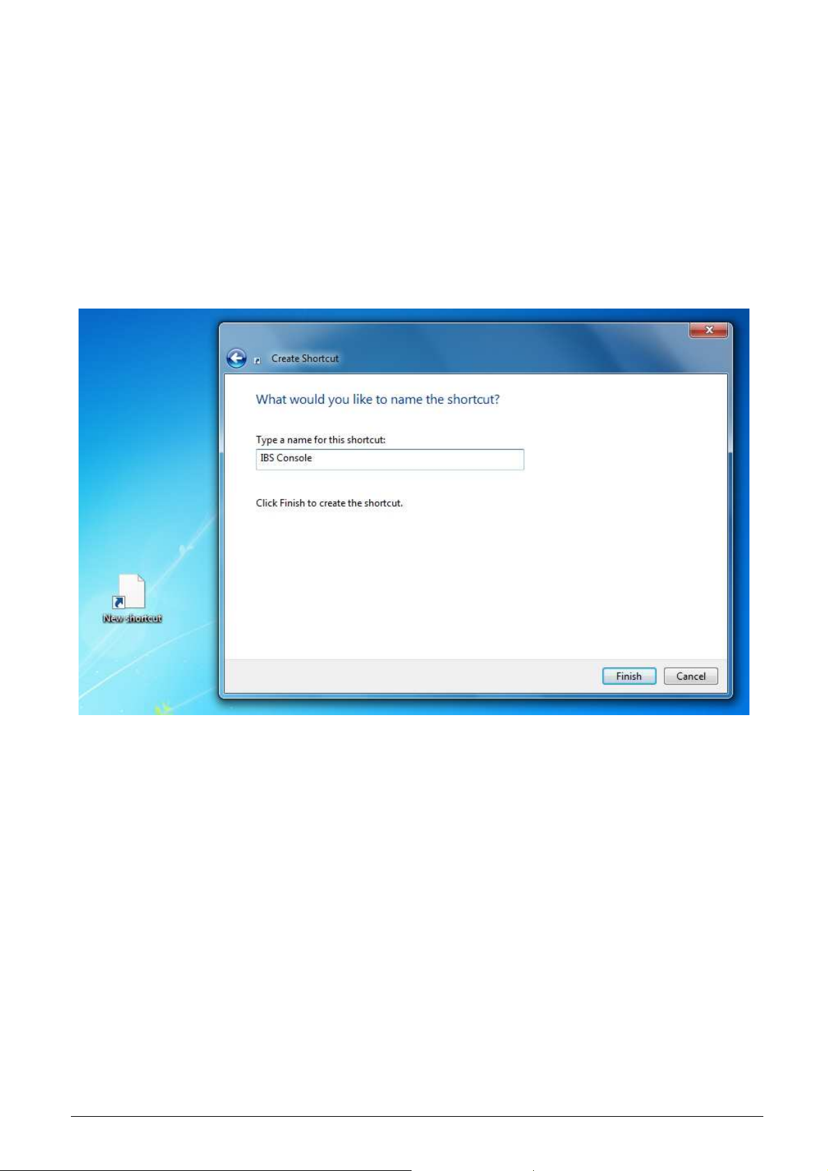
When done, click “Next” and enter the name for the shortcut and click “Finish”:
Figure G-17 Enter name for shortcut
IBS Precision Engineering
Machine Tool Console
Page 63 of 77
Page 64

When finished, the shortcut icon will default to the “runas.exe” icon from Windows rather than the
IBS Console icon. It is optional to set the icon back to the IBS Console. This may be executed as
follows:
Right click the shortcut and select “Properties”:
Figure G-18 Select shortcut properties
IBS Precision Engineering
Machine Tool Console
Page 64 of 77
Page 65

In the “Shortcut” Tab of the properties click “Change Icon…” which will show the “Change Icon”
message shown in figure G-19:
Figure G-19 Change icon
IBS Precision Engineering
Machine Tool Console
Page 65 of 77
Page 66

Click “OK” to open the screen containing the standard windows icons. Click “Browse…” and select
the application that the shortcut is pointing to (in this case “IBS_Console.exe”):
Figure G-20 Select correct icon
Click “Open”, “Apply” and “OK” to set the shortcut icon to the desired image.
IBS Precision Engineering
Machine Tool Console
Page 66 of 77
Page 67

G.6 Put the shortcut on the user desktop and activate
Once the shortcut is created on the administrator account’s desktop, the shortcut needs to be
copied to the desktop of the standard user.
To copy the shortcut to the user desktop, execute the following procedure:
Open Windows explorer and select “Users”, the name of the standard user account (in this case
“TestUser”) and “Desktop”:
Figure G-21 Copy shortcut to user desktop
Copy the shortcut from the administrator desktop to the desktop of the standard user account. See
Figure G-21.
To activate the shortcut, the administrator needs to switch from the administrator account to the
user account by pressing “Start”, the small arrow button at the right side of the “Shut down” button
and select “Switch user” (Fig. G-22):
Figure G-22 Switch to User account
IBS Precision Engineering
Machine Tool Console
Page 67 of 77
Page 68

Run the shortcut from the user desktop; the following command prompt will appear:
Figure G-23 Prompt shown on user account
Enter the administrator password (see section G-1) here once: the prompt will disappear and the
application will start with no additional password requests.
Note: when entering the administrator password, the cursor in the command prompt will NOT move
along: this is normal.
The next time the shortcut is run, the command prompt will show up very briefly, windows
‘remembers’ the credentials and will start the application with no further interference from the
administrator.
IBS Precision Engineering
Machine Tool Console
Page 68 of 77
Page 69

Appendix H Machine types explained
X
In the Console, 16 different machine tool configurations are implemented covering most existing
machine types used in industry:
A. Swivel head machines (5 machine types)
B. Trunnion table machines (7 machine types)
C. Mixed type machines (4 machine types)
Overview swivel head machines
Z
Y
S_VS_HT_AC
Y
X
Y
X
Z
X
S_HS_HT_AC
Z
Y
Z
S_HS_VT_AC
Y
X
S_HS_HT_BC
IBS Precision Engineering
Z
S_VS_HT_BC
Machine Tool Console
Page 69 of 77
Page 70

Overview trunnion table machines
Z
X
Y
T_VS_HT_AC
Z
Y
X
Y
X
T_HS_VT_AC
Y
X
Z
Z
T_VS_HT_BC
Z
Y
T_VS_VT_AB
Y
X
T_HS_VT_BC
Y
X
Z
X
T_HS_HT_AB
Z
T_HS_VT_BA
IBS Precision Engineering
Machine Tool Console
Page 70 of 77
Page 71

Overview mixed type machines
Z
Z
X
Y
M_VS_HT_AC
Z
X
Y
Z
X
Y
M_VS_HT_BC
Y
X
M_VS_HT_BA
Explanation machine code name:
MachineType_SpindleOrientation_TableOrientation_RotaryAxes
Machine Type: S (swivel head), T (Trunnion table) or M (Mixed type)
Spindle Orientation: HS (Horizontal Spindle), VS (Vertical Spindle)
Table Orientation: HT (Horizontal Table), VT (Vertical Table)
Rotary Axes: AC, AB, BA or BC.
M_HS_HT_AB
IBS Precision Engineering
Machine Tool Console
Page 71 of 77
Page 72

Appendix I EC Declaration of Conformity
IBS Precision Engineering
Machine Tool Console
Page 72 of 77
Page 73

IBS Precision Engineering
Machine Tool Console
Page 73 of 77
Page 74

Appendix J FCC Compliance Statement
This equipment has been tested and found to comply with the limits for a Class B digital device,
pursuant to Part 15 of the FCC Rules. These limits are designed to provide reasonable protection
against harmful interference in a residential installation.
This equipment generates, uses and can radiate radio frequency energy and, if not installed and
used in accordance with the instructions, may cause harmful interference to radio communications.
However, there is no guarantee that interference will not occur in a particular installation. If this
equipment does cause harmful interference to radio or television reception, which can be
determined by turning the equipment off and on, the user is encouraged to try to correct the
interference by one of the following measures:
• Reorient or relocate the receiving antenna.
• Increase the separation between the equipment and receiver.
• Connect the equipment into an outlet on a circuit different from that to which the receiver is
connected.
• Consult the dealer or an experienced radio/TV technician for help.
FCC Caution: To assure continued compliance, any changes or modifications not expressly
approved by the party responsible for compliance could void the user's authority to operate this
equipment.
This device complies with Part 15 of the FCC Rules. Operation is subject to the following two
conditions:
(1) This device may not cause harmful interference, and
(2) This device must accept any interference received, including interference that may cause
undesired operation.
Radiation Exposure Statement
This equipment complies with FCC RF radiation exposure limits set forth for an uncontrolled
environment. The antenna(s) used for this transmitter must be installed to provide a separation
distance of at least 20 cm from all persons and must not be co-located or operating in conjunction
with any other antenna or transmitter.
This equipment marketed in USA is restricted by firmware to only operate on 2.4 GHz channel 1-
11.
IBS Precision Engineering
Machine Tool Console
Page 74 of 77
Page 75

Notes (intentionally left blank)
IBS Precision Engineering
Machine Tool Console
Page 75 of 77
Page 76

Notes (intentionally left blank)
IBS Precision Engineering
Machine Tool Console
Page 76 of 77
Page 77

IBS Precision Engineering BV
Esp 201, 5633AD Eindhoven, The Netherlands
Telephone: +31 40 290 1270
E-mail: support@ibspe.com
www.ibspe.com
 Loading...