


=[MZ 5IV]IT
JL1710B
LCD Monitor

FCC COMPLIANCE STATEMENT
NOTE:
This equipment has been tested an d fo und to co mply with the limits for a
Class B digital device, pursuant to pa rt 15 o f the FCC Rules. These limits are
designed to provide reasonable protection against harmful interference in a
residential installation. This equipment gene rates, uses and can radiate radio
frequency energy and, if not installed a n d used in a cco rdance with the
instructions, may ca u s e harmful interference to radio commu n i c a tions. However,
there is no guarantee that interference will n o t occur in a particular installation.
If this equipment does cause harmful interference to radio o r television reception,
which can be determined by turning the eq uipment off and on, the user is
encouraged to try to correct the interference by one or more of the following
measures:
◎ Reorient or relocate the receiving antenna.
◎ Increase the separation between the equipment and receiver.
◎ Connect the equipment into an outlet on a circuit different from that to
Which the receiver is connected.
◎ Consult the dealer or an experienced radio/TV technician for help.
Modifications not expressly approved by the manufa cture r co uld void the user's
Authority to operated the equipment under FCC rules.
FCC Compliance Statement ......................................... i
Monitor Features......................................................... 2
General Information.................................................... 2
Safety Instructions....................................................... 3
Equipment Check list ................................................... 5
INTRODUCTION
Power Management .................................................. 12
Timing Guide............................................................... 13
Pin Assignment .......................................................... 14
Troubleshooting.......................................................... 15
Specifications ............................................................ 16
REFERENCE
Installation....................................................................... 6
Control Buttons............................................................... 7
On-Screen Display......................................................... 8
GETTING STARTED
Menu Descriptions....................................................... 9
ON-SCREEN
CONTROLS
TABLE OF CONTENTS
01
TABLE OF CONTENTS
02
MONITOR FEATURES
MONITOR FEATURES
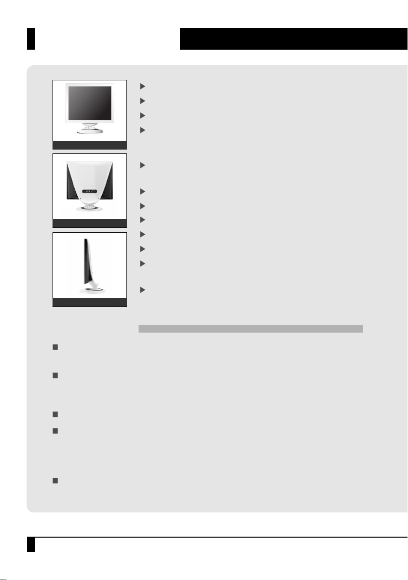
Supports Analog IBM compatible PC, Apple MacintoshTM(Adapter optional).
Supports DPMS for monitor power management.
Supports DDC2B.
On Screen Control: Contrast, Brightness, Color Temp, H-Position, V-Position
Phase, Clock, Auto Adjust, Auto Color, OSD H-Pos, OSD V-Pos, OSD Timer,
Language, Signal Source, Mode, Stand Light Timer.
Built-in color active matrix TFT (Thin Film Transistor) Liquid Crystal Display
(LCD) that uses amorphous silicon TFTs as a switching device.
Resolution: up to 1280X 1024.
Color: 16.2M Color support.
Pixel pitch: 0.264 mm (H) X 0.264 mm (W)
Scanning frequency: 30 KHz ~ 80 KHz (H), 55 Hz ~ 75 Hz (V).
Universal power supply: AC 100-240V allowed.
Power consumption Normal: 40 Watt Max.
Off: 3 Watt Max.
Outside dimension: 387 mm (W) X 394 mm (H) X 201.8 mm (D).
Front View
Rear View
Side View
General Information
Your new LCD monitor incorporates the latest state-of the art color Liquid Crystal
Display (LCD) technology providing a wider viewing angle with higher contrast ratio.
Your new LCD monitor has many advantages: safe from electromagnetic wave, lights,
sharps and slims. This makes the monitor extremely suitable in the environ ment of
administration, transportation system research, etc.
Your new LCD monitor is designed for Analog, Digital inputs.
Your new LCD monitor does not emit any X-ray radiation and the magnetic
emission greatly reduces the eyestrain. Moreover, our On Screen Controls on the front of
the panel provide flexibility with simple controls.
You can use these controls to adjust the display as you desire.
Your new LCD monitor incorporates an active TFT module. It has a 1280 X 1024 pixel
resolution, high contrast, wide viewing angle and colors up to 16.2M.
SAFETY INSTRUCTIONS
03
SAFETY INSTRUCTIONS
Caution
TO REDUCE THE RISK OF ELECTRIC SHOCK, DO NOT REMOVE
COVER (OR BACK). NO USER
SERVICEABLE PARTS INSIDE. REFER SERVICING
TO QUALIFIED SERVICE PERSONNEL.
CAUTION: RISK OF ELECTRIC SHOCK. DO NOT OPEN.
Do not open any covers on the monitor. No user serviceable parts are inside.
In an emergency, disconnect the AC power plug.
To avoid electrical shock, disconnect the power cord from the monitor before
connecting the signal cable to the computer.
Keep away from liquids and flame. Do not immerse this monitor in water or any
other liquid. Do not use this device in excessively hot conditions.
Handle the power cord with care. Do not bend the power cord excessively or
place heavy objects on it. Do not use a damaged power cord, doing so can result
in fire or electrical shock hazards.
When disconnecting the power cord, always grasp the plug, not the cord.
The liquid crystals in the display panel contain several irritants. If the panel is
damaged or broken, do not allow the liquid to come in contact with skin, eyes, or
mouth. If you come in contact with the liquid, flush the affected area with
running water for at least 15 minutes, then consult a doctor.
Handle this monitor with care when moving it. When lifting the monitor, support
it with one hand holding the stand, and one hand holding the LCD screen.
Always disconnect the power cord when moving this monitor.
Do not lay this monitor in a horizontal position when operating.
1
2
3
4
5
6
7
8
9

SAFETY INSTRUCTIONS
04
SAFETY INSTRUCTIONS
Handling
Due to its fragile glass panel, this monitor must be handled with caution and not be
exposed to impact or shock. Never touch the display area or rub it with a hard object
or tool, as the panel is easily scratched.
Cleaning
The display area is sensitive to scratching.
Do not use ketone-type cleaners (i.e. acetone), ethyl alcohol, toluene, ethyl acid or
methyl chloride to clean the panel. Doing so may result in permanent damage. Water,
IPA (Iso Prophyl Alcohol) and Hexane are safe cleaners. Do not allow oil or water to
penetrate the display, this will cause staining and discoloration. Avoid getting food
particles and fingerprints on the display area at all times.
Storage
Store the monitor in a dark place away from sunlight and ultraviolet (UV) radiation,
this may cause air bubbles to develop within the glass panel.
Do not store the display in temperatures higher than 104°F/40°C or humidity greater
than 90%. Avoid condensation.

05
EQUIPMENT CHECK LIST
EQUIPMENT CHECK LIST
Before operating your display, please check to make sure that all of the Items
listed are present in your package:
The monitor and items may not match the following illustrations exactly.
❖ Power Requirements
The monitor is equipped with an auto-sensing power supply for voltage ranging from
100-120VAC/200-240VAC, 50/60Hz. Confirm the power rating of the AC Source
before you plug the AC cable to the wall outlet.
AC to DC Adapter Power Cord User Manual
Monitor
Signal Cable (D-Sub) Signal Cable (DVI-D)

06
INSTALLATION
INSTALLATION
Signal Cable(DVI-D)
Monitor the Back View
PC the Back View
DC Adapter
Signal Cable(D-Sub)
DVI-D Panel
D-Sub Panel
Before you connect the cables, make sure that both the monitor and system unit power switches
are turned off.
Plug the 15-pin D-SUB and, or 24-pin DVI signal cable between the rear of your monitor and system.
The adapter may be required for certain Apple Macintosh computers.
Tighten the two screws on the cable connector.
Connect the power cord to the inlet socket which is located at the AC to DC Adapter.
Connect the plug into an AC wall outlet.
Connect DC Plug of AC to DC Adapter to the DC jack which is located at the rear of your monitor.
2
2
3
1
2
3
4
❖ Follow these steps to install the monitor
ƈ "No Cable, No Signal" message.
Before calling for service, check that the signal cable is firmly connected to the PC or the Monitor.
ƈ There may be few red, green, blue, white, or black pixels on the screen.
This is normal and not a defect of the unit. These pixels will have no impack on the performance of the
product.

07
CONTROL BUTTONS
CONTROL BUTTONS
OSD Buttons: The OSD control keys are located on the upper of the stand.
Button Description
a. No OSD : This button can be used for Auto Adjustment function. (Size, Phase)
Press this button for 3 seconds.
b. Main OSD menu : Press this button to exit from the main OSD menu.
c. OSD control Menu: Press this button to return to the previous menu.
a. No OSD : This button will enable the main OSD menu.
b. Main OSD menu: Press this button to enter to the selected OSD control menu.
a. Main OSD menu: Use these button to move up the OSD selection menu.
b. OSD control Menu: Use this button to increase each value.
AUTO
MENU
UP
a. Main OSD menu: Use these button to move down the OSD selection menu.
b. OSD control Menu: Use this button to decrease each value.
DOWN
Power Button : Turns the monitor on and off.

08
ON-SCREEN DISPLAY
ON-SCREEN DISPLAY
This LCD monitor features an On-Screen Display (OSD) menu. These icons are designed
to make your monitor display settings easier. When highlighted, the icons illustrate the
control function to assist you in identifying which control needs adjustment.
Before activating the OSD menu, the ‘AUTO’ button can be used to automatically adjust
the display to the proper size and horizontal and vertical position.
The OSD menu activates automatically when you press the ‘MENU’ button on the upper
of the stand. The OSD remains centered on the screen while you make your adjustments.
Use either the ‘UP’ or ‘DOWN’ button to move the highlight to your selection. ‘OSD’
sub menu or control with a status bar will appear.
The status bar indicates the direction which adjustments are being made. Use the ‘UP’ or
‘DOWN’ button to adjust the control.
When you have finished making adjustments, press the ‘AUTO’ button to save setting
and exit back to main menu.

09
MENU DESCRIPTIONS
MENU DESCRIPTIONS
Icon Description
Contrast
This control allows you to make adjustments to the contrast of the display screen.
Brightness
Selecting this control menu allows you to make adjustments to the luminosity level of the
display screen
H.Position
Select this control menu, and then use the ŕUPŖand ŕDOWNŖbuttons to center the image
horizontally on the screen.
Color Temp
Select this control menu, then use the ŕUPŖand ŕDOWNŖbuttons to scroll to the desired
color temperature. Use the ŕMENUŖbutton to select the 9300K, 6500K, 5500K or USER for
custom setting.
R-GAIN (RED)
Select
USER then use the MENU button to
scroll up and down the RGB menu to R (Red). Use
the
UP and DOWN
buttons to adjust the red
level of the display.
G-GAIN (GREEN)
Select
USER then use the MENU button to
scroll up and down the RGB menu to G (Green). Use
the
UP and DOWN buttons to adjust the green
level of the display.
B-GAIN (BLUE)
Select USER then use the MENU button to
scroll up and down the RGB menu to B (Blue). Use
the
UP and DOWN buttons to adjust the blue
level of the display.

10
MENU DESCRIPTIONS
MENU DESCRIPTIONS
Icon Description
Clock
Select this control menu, and then use the ‘UP’ and ‘DOWN’ buttons to expend or decrease
the image width to horizontally fill the display screen.
Auto Adjust
This control will automatically make adjustments to the horizontal and vertical size,
horizontal and vertical position, phase.
Phase
Select this control menu, and then use the ‘UP’ and ‘DOWN’ buttons to adjust the screen
image until it looks focused, crisp and sharp.
Auto Color
This control will automatically make adjustment to the input levels of video signal.
(ex. 0.714Vp-p, 1.0Vp-p)
OSD H,V POSITION
Select this control menu, and then use ŕUPŖand ŕDOWNŖbuttons to move the OSD menu
OSD TIMER Select this control menu, and then use the ŕMENUŖbutton to select the duration
time for the OSD menu. Use the ŕUPŖand ŕDOWNŖbuttons to select the time. (5 ~ 60 SEC)
OSD Timer
Select this control menu, and then use the ŕMENUŖbutton to select the duration time for the
OSD menu. Use the ŕUPŖand ŕDOWNŖbuttons to select the time. (5 ~ 60 SEC)
Language
Select this control menu, and then use the ‘UP’ and ‘DOWN’ buttons to choose from English
(ENGLISH), French (FRANÇAIS), German (DEUTSCH), Spanish (ESPAÑOL), Italian
(ITALIANO), Japanese (
) , Korean ( ).
V.Position
Select this control menu, and then use the ‘UP’ and ‘DOWN’ buttons to center the image
vertically on the screen.

11
MENU DESCRIPTIONS
MENU DESCRIPTIONS
Icon Description
Signal Source
Select this control menu, and then use the ‘UP’ and ‘DOWN’ buttons to select proper video
input signal either D-Sub (Analog R,G,B) or DVI-D (TMDS). Default setting is D-Sub.
Mode
Select this control menu, and then use the ‘UP’ and ‘DOWN’ buttons to select most proper
mode among the PC, GAME and MOVIE mode.
Stand Light Timer
Select this control menu, and then use the ŕMENUŖbutton to select the duration time
for the stand light. Use the ŕUPŖand ŕDOWNŖbuttons to select the time.
(ON: lighting for 10sec on touching the osd button, OFF: lighting continuously).

12
POWER MANAGEMENT
POWER MANAGEMENT
LED INDICATOR (POWER MANAGEMENT ACTIVE)
The power management feature is comprised of two stages:
On or Out Of Range (Blue), Off (Blue blinking). In the Off mode, all circuitry in the monitor is shut down,
except for a low power detection circuit. This circuit allows the monitor to wake up when the mouse
is moved or a key on the keyboard is pressed.
Power Mode
H-Sync V-Sync
LED Color
Video
Normal
Out Of Range
Suspend
Stand By
Off
Pulse
Pulse
Pulse
No Pulse
No Pulse
Pulse
Pulse
No Pulse
Pulse
No Pulse
Active
Active
Blanked
Blanked
Blanked
Blue
Blue
Blue Light Blink
(ON 0.5 sec / OFF 1.0 sec)
Blue Light Blink
(ON 0.5 sec / OFF 1.0 sec)
Blue Light Blink
(ON 0.5 sec / OFF 1.0 sec)

13
TIMING GUIDE
TIMING GUIDE
If you use a Macintosh computer, you may need a Mac adapter.
The LCD is a multi-frequency display. It operates at horizontal frequencies between 30KHz-80KHz
and vertical frequencies between 55Hz-75Hz. Because of its microprocessor-based design, it offers
auto- synchronization and auto-sizing capabilities. This monitor offers 10 pre- programmed settings
that are listed in the following time table.
These preset modes cover most of the common video modes supported by popular graphics
adapters. However, each adapter's implementation of these video modes may vary slightly.
If you find it necessary to make minor display adjustments (for example, horizontal and vertical
position), please refer to the On Screen Display section of this manual for instructions.
If you would like to use one of the preset timing modes, please refer to your video card
manufacturer's installation guide for instructions on how to make these changes. The video card
controls the refresh rate. Most Video cards provide a software utility or hardware DIP switches that
allows you to change the frequency used for each resolution.
Preset
Horizontal
[Dots]
Vertical
[Lines]
VGA
VESA
MAC
M1
M2
M3
M4
M5
M6
M7
M8
M9
M10
720
640
640
800
800
1,024
1,024
1,280
1,280
832
31.5
31.5
37.5
37.9
46.9
48.4
60.0
64.0
80.0
49.7
70
60
75
60
75
60
75
60
75
75
28.322
25.175
31.500
40.000
49.500
65.000
78.750
108.000
135.000
57.284
Polarity
[H/V]
-
/+
-
/
-
-
/
-
+/+
+/+
-/-
+/+
+/+
+/+
-/-
400
480
480
600
600
768
768
1,024
1,024
624
Clock
[MHz]
Frequency
Vertical
[Hz]
Horizontal
[KHz]
Resolution
[Timing Table]

14
PIN ASSIGNMENT
PIN ASSIGNMENT
VGA Connection (Cable Side)
DVI Connection (Cable Side)
9
12345678
10111213141516
1718192021222324
Pin
1
2
3
4
5
6
7
8
Red
Green
Blue
No Connection
Ground
Red Ground
Green Ground
Blue Ground
Signal
Pin
9
10
11
12
13
14
15
No Connection
Ground
Ground
DDC SDA
Horizontal Sync.
Vertical Sync.
DDC SCL
Signal
Pin
1
2
3
4
5
6
7
8
9
10
11
12
T.M.D.S. Data2-
T.M.D.S. Data2+
T.M.D.S. Data2/4 Shield
T.M.D.S. Data4- (N,C)
T.M.D.S. Data2+ (N,C)
DDC Clock
DDC Data
N,C
T.M.D.S. Data1-
T.M.D.S. Data1+
T.M.D.S. Data1/3 Shield
T.M.D.S. Data3- (N,C)
Signal
Pin
13
14
15
16
17
18
19
20
21
22
23
24
T.M.D.S.
Data
3+
(N,C)
+5V Power
GND (for+5V)
Hot Plug Detect
T.M.D.S. Data0
T.M.D.S. Data0+
T.M.D.S. Data0/5
T.M.D.S. Data5- (N,C)
T.M.D.S.
Data
5+
(N,C)
T.M.D.S. Clock Shield
T.M.D.S. Clock+
T.M.D.S. Clock-
Signal
DVI-D Connector (TMDS Single Link)
When resolutions are shown that are lower than the pixel count of the LCD panel, text may appear
choppy or bold. This is normal for all current flat panel technologies when displaying non-native resolutions on a full screen (below than 1280°ø1024 resolution). In flat panel technologies, each dot on the
screen is actually one pixel, so to expand resolutions to full screen, an interpolation of the resolution
must be down. When the interpolated resolution is not an exact multiple of the native resolution, the
mathematical interpolation necessary may cause some lines to appear thicker than others.
VGA CONNECTOR
POWER JACK (Monitor Side)
Ground DC+12V input

15
TROUBLESHOOTING
TROUBLESHOOTING
Problem Possible Solution
No power
Power on but no
screen image
Image is unstable,
unfocused.
Flickering
Wrong or
abnormal colors
Entire screen image
rolls (scrolls)
vertically.
Double (split) screen image
Control buttons do not work.
Flip the power switch ON. The Power LED turns on.
Make sure AC power cord is securely connected to a
power outlet.
Make sure the video cable attached with this monitor is
tightly secured to the video output port on the back of the
computer.
Adjust the brightness and contrast.
Use "AUTO-TUNE" to adjust automatically.
If the image is still unstable after "AUTO-TUNE" processing,
please adjust "PHASE" manually to get image focused.
Check whether the resolution or refresh rate in windows
display setting is beyond supported range (please refer to the
specification of supported mode).
Not enough power is being supplied to the LCD Monitor.
Connect the LCD Monitor to a different outlet. If a surge
protector is being used, there may be too many devices
plugged in.
See Timing Guide in this manual with a list of refresh rates and
frequency settings showing the recommended setting for the
LCD Monitor
If any colors (Red, Green, or Blue) are missing, check the video
cable to make sure it is securely connected. Loose pins
in the cable connector could cause a bad connection.
Connect the LCD Monitor to another computer.
Check the graphics card for proper sync scheme (or sync
polarities) to match the LCD Monitor's specifications.
Make sure your graphics card is set to Non-Interlaced mode.
Make sure the input signals are within the LCD monitor's
specified frequency range.
(Maximum: VESA, MAC 1280 X 1024 (75 Hz)
Connect the video cable securely.
Try the this Monitor with another power source.
Press only one button at a time.

16
SPECIFICATIONS
SPECIFICATIONS
LCD Panel
Viewing Angles
Freguency
Contrast Ratio
Compatibility
Display Resolution
Connectors
Power
Operating
Storage
Conditions
Dimension
Weight
JL1710B LCD Monitor
17`` Diagonal
337.92mm (0) Ŧ 270.336mm (>)
TFT active matrix
0.264 Ŧ 0.264mm
ŊŊ
ŊŊ
30~80 KHz
55~75 Hz
16.2M KWTWZ[
)V\QOTIZMKWI\QVO
700:1
300cd/m
2
IBM XT, AT, 386, 486, Pentium or PS/2 and compatibles
(from VGA and DVI up to 1280X1024@75 Hz)
1280X1024@75Hz (60 Hz for optimal display)
15-pin D-SUB, 24-pin DVI
Jack Type DC+12V In
AC 100-240V, 50-60 Hz
DC 12V
40 watts (Maximum)
32ŊF to 104ŊF (0ŊC to 40ŊC)
20% RH to 80% RH (no condensation)
To 10,000 feet
-13ŊF to 104ŊF (-25ŊC to 40ŊC)
5% RH to 90% RH (no condensation)
387 mm (W) X 394 mm (H) X 201.8 mm (D)
5.0Kg (11 lbs)
Size
Display Size
Type
Pixel Pitch
Left / Right
Up / Down
Horizontal Sync
Vertical Sync
Display Color
Surface Treatment
Typ.
Typ.
PC
Max.
Input Signal
Power
Input
Output
Consumption
Temperature
Humidity
Altitude
Temperature
Humidity
Net
Luminance of White

17
MEMO
MEMO

 Loading...