

Page 1

Remote Supervisor Adapter
User’ s Guide
Page 2

Page 3

Remote Supervisor Adapter
User’ s Guide
Page 4

Note: Before using this information and the product it supports, be sure to read the general information in Appendix B, “Notices” on
page 109.
Sixth Edition (October 2002)
© Copyright International Business Machines Corporation 2001, 2002. All rights reserved.
US Government Users Restricted Rights – Use, duplication or disclosure restricted by GSA ADP Schedule Contract
with IBM Corp.
Page 5

Contents
Chapter 1. Introduction ......................1
Remote Supervisor Adapter features .................1
Web browser requirements .....................2
Notices used in this book .....................2
Chapter 2. Opening and using the ASM Web interface .........3
Logging in to the Remote Supervisor Adapter ..............3
Logging in to the ASM processor in an xSeries 330 server .........6
Remote Supervisor Adapter and ASM processor action descriptions ......7
Remote Supervisor Adapter action descriptions in xSeries 330 servers .....9
Chapter 3. Configuring your Remote Supervisor Adapter or ASM processor 13
Setting system information ....................14
Setting server timeouts .....................15
Setting the date and time ....................18
Creating a login profile ......................19
Setting the global login settings ...................21
Configuring remote alert settings ..................22
Configuring remote alert recipients.................22
Forwarding alerts .......................25
Setting remote alert attempts...................25
Setting remote alerts ......................26
Setting local events ......................29
Configuring the serial port .....................29
Initialization-string guidelines ...................33
Configuring network interfaces ...................34
Configuring an Ethernet connection to the Remote Supervisor Adapter . . . 34
Configuring PPP access over a serial port ..............36
Configuring network protocols ...................38
Configuring SNMP ......................38
Configuring SMTP.......................41
Configuring remote control keys ..................41
Using the configuration file ....................42
Backing up your current configuration ...............42
Restoring and modifying your ASM configuration ...........43
Restoring ASM defaults......................43
Restarting ASM .........................44
Logging off ..........................44
Chapter 4. Monitoring remote server status .............45
Viewing system health ......................45
Viewing the event log ......................49
Viewing vital product data .....................51
Chapter 5. Performing Remote Supervisor Adapter tasks ........55
Server power and restart activity ..................56
Remotely controlling the power status of a server ............57
Remote boot (start) .......................58
Remote control .........................59
Accessing the server graphical console ...............59
Viewing the server POST ....................60
Viewing the server blue screen ..................60
Updating firmware ........................61
© Copyright IBM Corp. 2001, 2002 iii
Page 6

Accessing remote adapters through an ASM interconnect network ......62
Chapter 6. Starting and configuring the ASM text-based interface ....65
Accessing the text-based interface through a Telnet connection .......65
Accessing the text-based interface through a direct serial connection .....66
Configuring terminal settings ....................66
Accessing remote adapters through an ASM interconnect network ......67
Chapter 7. Configuring your Remote Supervisor Adapter using a
text-based interface ......................69
Setting system information ....................69
Setting server timeouts ......................71
Creating a login profile ......................73
Setting modem and dial-in settings .................76
Configuring remote alert recipients..................77
Setting remote alert attempts....................80
Setting remote alerts .......................81
Configuring the serial port .....................84
Initialization-string guidelines ....................86
Configuring network interfaces ...................87
Configuring an Ethernet connection to the Remote Supervisor Adapter . . . 87
Configuring PPP access over the serial port .............90
Configuring network protocols ...................91
Configuring SNMP ......................91
Configuring DNS .......................93
Configuring SMTP.......................94
Setting the Remote Supervisor Adapter and ASM processor clocks......94
Chapter 8. Checking system health and performing tasks through the
text-based interface ......................97
Monitoring temperature, voltage, and fan readings ............97
Viewing the event log ......................99
Viewing vital product data ....................100
Performing Remote Supervisor Adapter tasks through a text-based interface 102
Remotely controlling the power status of a server...........103
Viewing the server text console .................104
Restoring ASM defaults ....................105
Restarting ASM .......................106
Logging off .........................106
Appendix A. Getting help and technical assistance ..........107
Before you call ........................107
Using the documentation .....................107
Getting help and information from the World Wide Web .........107
Software service and support ...................108
Hardware service and support ...................108
Appendix B. Notices ......................109
Edition notice .........................109
Trademarks..........................110
Important notes ........................110
Index ............................113
iv Remote Supervisor Adapter: User’s Guide
Page 7

Chapter 1. Introduction
This manual explains how to use the functions of the IBM®Remote Supervisor
Adapter when you install it in an IBM Eserver xSeries™server. The IBM Remote
Supervisor Adapter is one of the products in the Advanced System Management
(ASM) family. The Remote Supervisor Adapter provides around-the-clock remote
access and system management of your server and supports the following:
v Remote management independent of the status of the managed server
v Remote control of hardware and operating systems
v Web-based management with standard Web browsers (no other software is
required)
v Text-based user interface
You can use either the ASM Web interface or the text-based interface to access the
Remote Supervisor Adapter. The ASM Web interface is described in Chapter 2
through Chapter 5 and the text-based interface is described in Chapter 6 through
Chapter 8.
Remote Supervisor Adapter features
Standard features of the Remote Supervisor Adapter are as follows:
v Continuous health monitoring and control
v Automatic notification and alerts
v Battery-backed event log showing time-stamped entries
v Remote access through Ethernet, point-to-point protocol (PPP) connection, serial
port, and ASM interconnect peer-to-peer network
v Full Simple Network Management Protocol (SNMP) support
v E-mail alerts
v Alphanumeric or numeric pager alerts
v Domain Name System (DNS) server support
v Dynamic Host Configuration Protocol (DHCP) support
v Remote power control
v Blue screen capture (not supported on all servers)
v Remote firmware update
v Access to critical server settings
v Text-based user interface terminal access
v Redirection of the server graphical or text console (not supported on all servers)
v Access to server vital product data (VPD)
v Remote start (boot) from a diskette image
© Copyright IBM Corp. 2001, 2002 1
Page 8

Web browser requirements
The Remote Supervisor Adapter supports the following Web browsers for remote
access. The Web browser that you use must be Java™-enabled and must support
JavaScript
v Microsoft
v Netscape Navigator version 4.72, or later (version 6.x is not supported)
Notes:
1. Java plug-in version 1.4 or later is required for the remote start (boot) feature,
2. For best results when using the ASM Web interface, set the resolution on your
3. The ASM Web interface and the ASM text-based interface do not support the
™
1.2 or later.
®
Internet Explorer version 4.0 (with Service Pack 1), or later
which is not available on all servers.
monitor to 800 x 600 pixels and 256 colors.
double-byte character set (DBCS) languages.
Notices used in this book
The following notices are used in the documentation:
v Notes: These notices provide important tips, guidance, or advice.
v Important: These notices provide information or advice that might help you avoid
inconvenient or problem situations.
v Attention: These notices indicate potential damage to programs, devices, or
data. An attention notice is placed just before the instruction or situation in which
damage could occur.
2 Remote Supervisor Adapter: User’s Guide
Page 9
Chapter 2. Opening and using the ASM Web interface
To access the Remote Supervisor Adapter remotely using the ASM Web interface,
you must log in to the adapter. This chapter describes the login procedures and
describes the actions you can perform from the ASM Web interface.
For an xSeries 330 server: Certain features of the ASM Web interface and
text-based interface are available only through the ASM processor that is integrated
on the system board of an xSeries 330 server. You must first log in to the Remote
Supervisor Adapter and then log in to the ASM processor for full feature support.
For information about using the text-based user interface, see Chapter 6, “Starting
and configuring the ASM text-based interface” on page 65.
Logging in to the Remote Supervisor Adapter
Complete the following steps to access the Remote Supervisor Adapter through the
ASM Web interface.
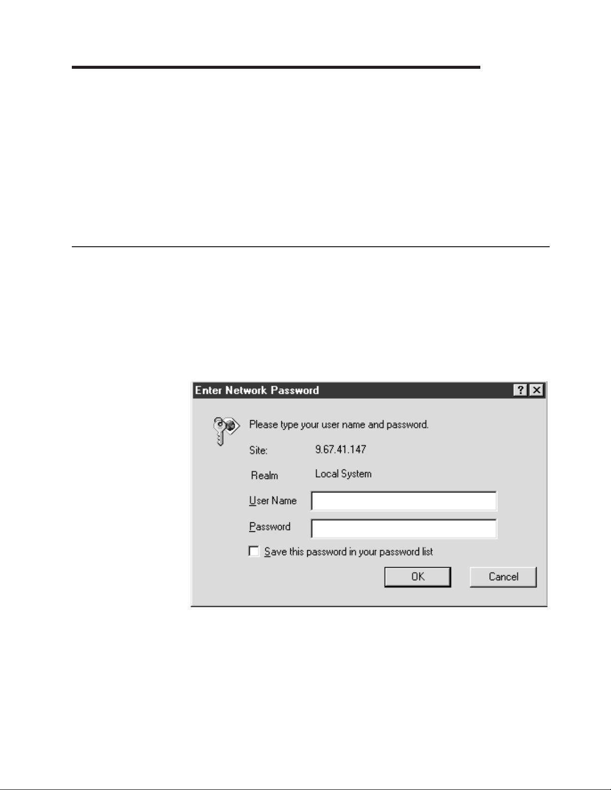
1. Open a Web browser. In the address or URL field, type the IP address or host
name of the Remote Supervisor Adapter to which you want to connect.
The Enter Network Password window opens.
Note: The values in the following window are examples. Your settings will be
different.
2. Type your user name and password in the Enter Network Password window. If
you are using the Remote Supervisor Adapter for the first time, you can obtain
your user name and password from your system administrator. All login attempts
are documented in the event log. A welcome page opens in your browser.
Note: The Remote Supervisor Adapter is set initially with a user name of
USERID and password of PASSW0RD (with a zero, not an O). This user has
read/write access. Change this default password during your initial
© Copyright IBM Corp. 2001, 2002 3
Page 10
configuration for enhanced security.
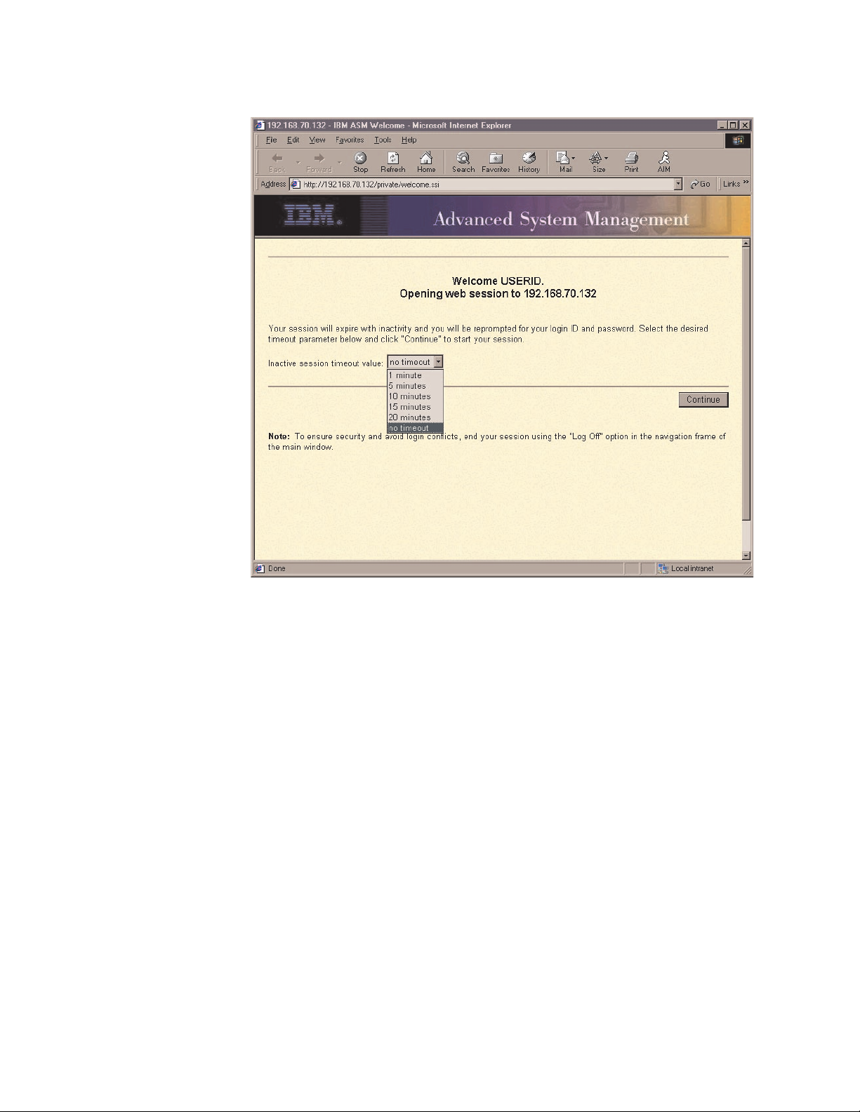
3. Select a timeout value from the drop-down list in the field provided. If your
browser is inactive for that number of minutes, the Remote Supervisor Adapter
logs you off the ASM Web interface.
4. Click Continue to start the session.
The window that opens depends on the type of server in which the Remote
Supervisor Adapter is installed.
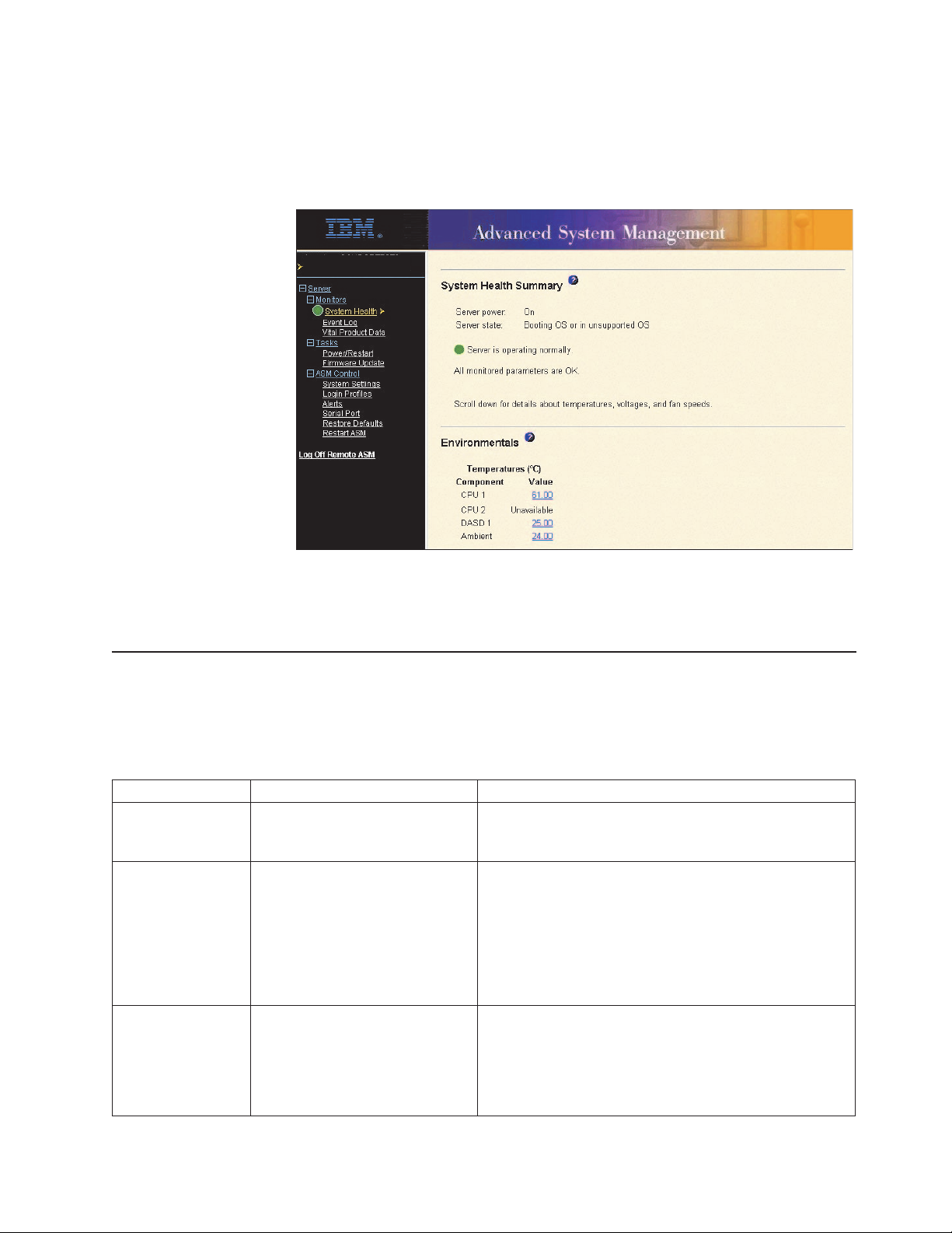
v If you are logging in to a Remote Supervisor Adapter installed in a server
other than an xSeries 330, the browser opens the System Health page, which
4 Remote Supervisor Adapter: User’s Guide
Page 11
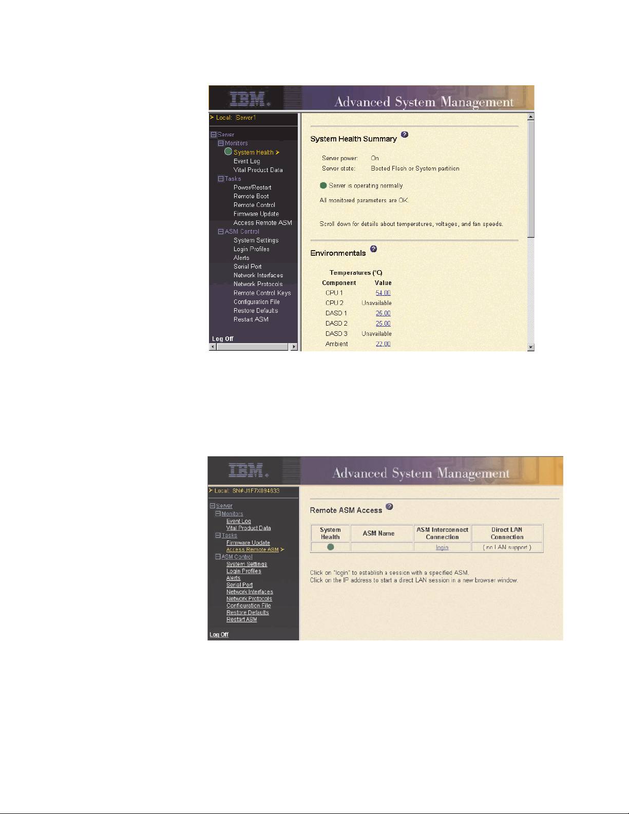
gives you a quick view of the server status.
For descriptions of the actions that you can perform from the links in the left
navigation pane of the ASM Web interface, see “Remote Supervisor Adapter
and ASM processor action descriptions” on page 7. Then, go to Chapter 3,
“Configuring your Remote Supervisor Adapter or ASM processor” on page 13.
v If you are logging in to a Remote Supervisor Adapter installed in an xSeries
330 server, the browser opens a window similar to the one in the following
illustration.
ASMDEMO
For descriptions of the actions that you can perform from the links in the left
navigation pane of the ASM Web interface, see “Remote Supervisor Adapter
action descriptions in xSeries 330 servers” on page 9. Then, go to either
“Logging in to the ASM processor in an xSeries 330 server” on page 6 or
Chapter 3, “Configuring your Remote Supervisor Adapter or ASM processor”
on page 13.
Chapter 2. Opening and using the ASM Web interface 5
Page 12
Logging in to the ASM processor in an xSeries 330 server
The integrated ASM processor on the system board of an xSeries 330 server
enables you to monitor the health of the managed server, view the server event log
and vital product data, configure alerts and alert recipients, and perform power and
restart operations on the server.
If you have a Remote Supervisor Adapter installed in an xSeries 330 server, you
must log in to the Remote Supervisor Adapter and then log in to the ASM processor
for full feature support.
Complete the following steps to log in to an ASM processor in an xSeries 330
server:
1. Log in to the Remote Supervisor Adapter. For more information, see “Logging in
to the Remote Supervisor Adapter” on page 3.
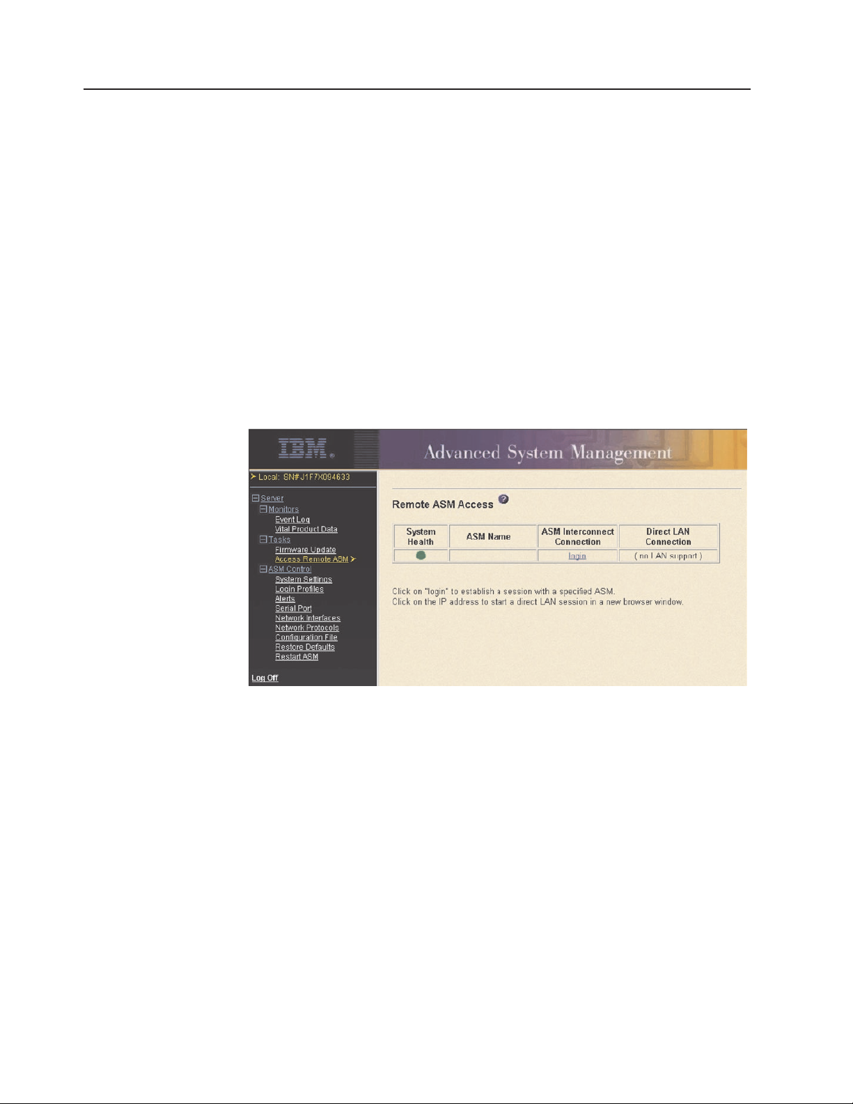
2. In the Remote ASM Access page that is displayed, you can view a list of the
ASM processors, ASM PCI adapters, and Remote Supervisor Adapters in the
ASM interconnect network and the local system that contains the Remote
Supervisor Adapter.
ASMDEMO
3. In the ASM Interconnect Connection column, locate the entry that matches
the ASM processor on the xSeries 330 server that you want to monitor; then,
click login .
Note: It is important that each ASM processor has a meaningful name so that
you can easily identify the correct server to monitor. The name of the
ASM processor is what you select from the table in the ASM
Interconnect Connection column. If you are not sure of the name of the
ASM processor for the server that you want to monitor, log in to each
ASM processor individually and view the vital product data (VPD) to
determine the serial number of the server in which that ASM processor is
located.
4. The Enter Network Password window opens. Type your user name and
password. If you are accessing the ASM processor for the first time, you can
obtain your user name and password from your system administrator. All login
attempts are documented in the event log.
6 Remote Supervisor Adapter: User’s Guide
Page 13
Note: The ASM processor is set initially with a user name of USERID and
password of PASSW0RD (with a zero, not an O). This user has read/write
access. Change this default password during your initial configuration for
enhanced security.
5. The System Health page for the monitored server is displayed.
Local: Server 1
Remote: ASMDEMO
For descriptions of the actions that you can perform from the links in the left
navigation pane of the ASM Web interface, see “Remote Supervisor Adapter action
descriptions in xSeries 330 servers” on page 9.
Remote Supervisor Adapter and ASM processor action descriptions
Table 1 lists the actions available when you are logged in to the Remote Supervisor
Adapter in non-xSeries 330 servers or the ASM processor in an xSeries 330 server.
Table 1. Actions available when logged in to a Remote Supervisor Adapter or when logged in to the ASM processor
in an xSeries 330 server
Link Action Description
System Health View system health for a server You can monitor the server power and state and the
temperature, voltage, and fan status of your server on the
System Health page.
Event Log View event logs for remote
servers
Vital Product Data View the server and ASM
processor VPD
The Event Log page contains entries that are currently
stored in the server event log and power-on self-test
(POST) event log. Information about all remote access
attempts and dial-out events are recorded in the event log.
All events in the log are time-stamped using either the
Remote Supervisor Adapter or the ASM processor date
and time settings. Some events will also generate an alert,
if configured to do so on the Alerts page.
Upon server startup, the Remote Supervisor Adapter or
ASM processor collects system information and basic
input/output system (BIOS) information, and server
component vital product data (VPD) and stores it in
nonvolatile memory. This data is available from the Vital
Product Data page.
Chapter 2. Opening and using the ASM Web interface 7
Page 14

Table 1. Actions available when logged in to a Remote Supervisor Adapter or when logged in to the ASM processor
in an xSeries 330 server (continued)
Link Action Description
Power/Restart Remotely power on or restart a
server
The Remote Supervisor Adapter or ASM processor
provides full remote power control over your server with
power-on, power-off, and restart actions. In addition,
power-on and restart statistics are captured and displayed
to show server hardware availability.
Remote Boot Remotely start (boot) your server
from a diskette image
Use the options in the Remote Boot page to remotely start
(boot) your server from a newly created diskette image or
from a previously created and saved diskette image.
Remote Control Redirect the server graphical
console or server text console,
restart the server and view the
POST, and view the blue screen
From the Remote Control page, you can redirect the
server graphical console, redirect the server text console,
restart the server and view the POST process, and view
the image of the last Windows
®
blue screen capture.
capture
Firmware Update Update firmware on the Remote
Supervisor Adapter or ASM
processor
Use the options on the Firmware Update page to update
firmware of the Remote Supervisor Adapter or ASM
processor and server components such as server BIOS
code and server diagnostics.
Access Remote
ASM
Access other system-management
processors and adapters
1
on the
ASM interconnect network
From the Access Remote ASM page, you can view a list of
system-management processors and adapters1present on
the ASM interconnect network and establish a connection
to any of those systems.
System Settings View the Remote Supervisor
Adapter or ASM processor system
settings
You can configure general information, such as the name
of the Remote Supervisor Adapter or ASM processor,
server timeout settings, and contact information for the
Remote Supervisor Adapter, and the server location from
the System Settings page.
Set the Remote Supervisor
Adapter or ASM processor clock
You can set the Remote Supervisor Adapter and ASM
processor clocks that are used for time stamping the
entries in the event log.
Login Profiles Configure the ASM processor
login profiles
You can define 12 login profiles that enable access to the
Remote Supervisor Adapter or ASM processor.
Alerts Configure local events You can set the local events monitored by the Remote
Supervisor Adapter or ASM processor, for which
notifications are sent to IBM Director.
Configure remote alerts and
remote alert recipients
You can configure the Remote Supervisor Adapter or ASM
processor to generate and forward alerts for a number of
different events. You can configure the alerts that are
monitored and the recipients that are notified on the Alerts
page.
Configure alert settings You can set the number of alert retries and the delay
between the retries.
Serial Port Dedicate a serial port to the
Remote Supervisor Adapter or the
ASM processor or share access
with a host server
From the Serial Port page, you can configure the serial
port and modem settings used by the Remote Supervisor
Adapter or ASM processor.
Note: The ASM processor uses the serial port on the
server. If a Remote Supervisor Adapter is installed in an
xSeries 330 server, you can configure one of the serial
ports to be shared with the operating system running on
the server and the other serial port always to be dedicated
to the ASM processor.
8 Remote Supervisor Adapter: User’s Guide
Page 15

Table 1. Actions available when logged in to a Remote Supervisor Adapter or when logged in to the ASM processor
in an xSeries 330 server (continued)
Link Action Description
Network Interfaces Configure the network interfaces
of the Remote Supervisor Adapter
Network Protocols Configure the network protocols of
the Remote Supervisor Adapter
Remote Control
Keys
Configuration File Back up and restore the Remote
Restore Defaults Restore the Remote Supervisor
Restart ASM Restart the Remote Supervisor
Log Off Remote
ASM
Log off Log off the Remote Supervisor
1
System-management processors and adapters are Remote Supervisor Adapters, ASM processors, ASM PCI
adapters, and integrated system management processors (ISMPs). These system-management processors and
adapters are also known as service processors.
Transmit special key combinations During server console redirect and remote POST,
Supervisor Adapter configuration
Adapter or ASM processor
defaults
Adapter or ASM processor
Log off a remote
system-management processor or
adapter
Adapter
1
You can configure network-access settings to the Remote
Supervisor Adapter from the Network Interfaces page,
which is available only when you log in to the Remote
Supervisor Adapter. The Remote Supervisor Adapter
supports both Ethernet and point-to-point protocol (PPP)
connections, enabling remote access using a Web browser
or Telnet application.
You can configure Simple Network Management Protocol
(SNMP), Domain Name System (DNS), and Simple Mail
Transfer Protocol (SMTP) settings used by the Remote
Supervisor Adapter from the Network Protocols page,
which is available only when you log in to the Remote
Supervisor Adapter.
keyboard support is limited to ASCII characters, the arrow
keys, and the F1 through F12 function keys. To transmit
certain special key combinations, you must type the
default prefix key combination or a user-defined prefix key
combination, followed by a second key, as described in the
special keys table.
You can back up, modify, and restore the configuration of
the Remote Supervisor Adapter from the Configuration File
page.
Attention: When you click Restore Defaults, all of the
modifications you made to the Remote Supervisor Adapter
or ASM processor are lost.
You can reset the configuration of the Remote Supervisor
Adapter or ASM processor to the factory defaults.
You can restart the Remote Supervisor Adapter or ASM
processor.
You can log off your connection to the
system-management processor or adapter
interconnect network and return to the Remote Supervisor
Adapter that originated the remote session.
You can log off your connection to the Remote Supervisor
Adapter.
1
on the ASM
You can click the View Configuration Summary link, which is available on most
pages, to quickly view the configuration of the Remote Supervisor Adapter or ASM
processor.
Remote Supervisor Adapter action descriptions in xSeries 330 servers
Table 2 on page 10 lists the actions available when you are logged in to the Remote
Supervisor Adapter installed in an xSeries 330 server.
Note: When you are logged in to a Remote Supervisor Adapter installed in an
xSeries 330 server or an ASM processor in an xSeries 330 server, the link
Chapter 2. Opening and using the ASM Web interface 9
Page 16

names used by the ASM Web interface are identical; however, the
information and functions that are supported differ. In the following table,
these features are explained as they function when you are logged in to the
Remote Supervisor Adapter and not the ASM processor.
Table 2. Actions available when logged in to the Remote Supervisor Adapter installed in an xSeries 330 server
Link Action Description
Event Log View the event log for Remote
Supervisor Adapter events
Vital Product Data View the Remote Supervisor
Adapter vital product data (VPD)
Firmware Update Update the Remote Supervisor
Adapter firmware
Access Remote ASM Access other
system-management processors
or adapters on the ASM
interconnect network
System Settings Configure the system settings You can configure information about the Remote
Set the Remote Supervisor
Adapter clock
Login Profiles Configure login profiles on the
Remote Supervisor Adapter
Alerts Configure alert forwarding The Remote Supervisor Adapter forwards alerts
Serial Port Configure the serial port of a
Remote Supervisor Adapter
Network Interfaces Configure the network interfaces
of the Remote Supervisor Adapter
Network Protocols Configure the network protocols
of the Remote Supervisor Adapter
The event log window contains information specific to
the Remote Supervisor Adapter, such as remote access
attempts and dial-out events. All events in the log are
time-stamped using the Remote Supervisor Adapter
clock.
You can view information about the Remote Supervisor
Adapter firmware data from the Vital Product Data
window.
You can update the firmware of the Remote Supervisor
Adapter from the Firmware Update window.
You can view a list of system-management processors
and adapters
establish a connection to any of those systems.
Supervisor Adapter, such as the name, contact, and
location information on the System Settings window.
You can set the clock used by the Remote Supervisor
Adapter for time-stamping the entries in the event log.
You can define up to 12 login profiles that enable
access to the Remote Supervisor Adapter from the
Login Profiles window.
generated by the ASM processor. It does not generate
alerts on its own. You can configure settings for
forwarding alerts from the Alerts window.
You can configure the serial port and modem settings
used by the Remote Supervisor Adapter from the Serial
Port window.
Note: The serial port used by the Remote Supervisor
Adapter is different from the serial port used by the
ASM processor. The Remote Supervisor Adapter has a
dedicated serial port.
You can configure network-access settings to the
Remote Supervisor Adapter from the Network Interfaces
window, which is available only when you log in to the
Remote Supervisor Adapter. The Remote Supervisor
Adapter supports both Ethernet and point-to-point
protocol (PPP) connections, enabling remote access
using a Web browser or Telnet application.
You can configure Simple Network Management
Protocol (SNMP), Domain Name System (DNS), and
Simple Mail Transfer Protocol (SMTP) settings used by
the Remote Supervisor Adapter from the Network
Protocols window, which is available only when you log
in to the Remote Supervisor Adapter.
1
on the ASM interconnect network and
10 Remote Supervisor Adapter: User’s Guide
Page 17

Table 2. Actions available when logged in to the Remote Supervisor Adapter installed in an xSeries 330
server (continued)
Link Action Description
Configuration File Back up and restore the Remote
Supervisor Adapter configuration
You can back up, modify, and restore the configuration
of the Remote Supervisor Adapter from the
Configuration File window.
Restore Defaults Restore the Remote Supervisor
Adapter defaults
You can reset the Remote Supervisor Adapter
configuration to the factory defaults from the Restore
Defaults window.
Restart ASM Restart the Remote Supervisor
Adapter
Log Off Log off the Remote Supervisor
Adapter
1
System-management processors and adapters are Remote Supervisor Adapters, ASM processors, ASM PCI
You can restart the Remote Supervisor Adapter from
the Restart ASM window.
You can log off from the Remote Supervisor Adapter
from the Log Off window.
adapters, and integrated system management processors (ISMPs). These system-management processors and
adapters are also known as service processors.
You can click the View Configuration Summary link, which is available on most
pages, to quickly view the configuration of the Remote Supervisor Adapter.
Chapter 2. Opening and using the ASM Web interface 11
Page 18

12 Remote Supervisor Adapter: User’s Guide
Page 19

Chapter 3. Configuring your Remote Supervisor Adapter or ASM processor
Use the links under ASM Control in the navigation pane to configure the Remote
Supervisor Adapter or the ASM processor in an xSeries 330 server. The features
available to you depend on whether you are logged in to a Remote Supervisor
Adapter, the server type in which the Remote Supervisor Adapter is installed, or
whether you are logged in to an ASM processor.
v From the System Settings page, you can:
– Set system information
– Set server timeouts
– Set ASM date and time
v From the Login Profiles page, you can:
– Set login profiles to control access to the Remote Supervisor Adapter
– Configure modem and dial-in settings
v From the Alerts page, you can:
– Set integrated system management processor (ISMP) alert forwarding
– Configure remote alert recipients
– Set the number of remote alert attempts
– Select the delay between alerts
– Select which alerts will be sent and how they will be forwarded
v From the Serial Port page, you can:
– Configure the serial port of the Remote Supervisor Adapter
– Configure advanced modem settings
v From the Network Interfaces page, you can:
– Set up an Ethernet connection
– Set up a PPP over serial port connection
v From the Network Protocols page, you can:
– Configure SNMP setup
– Configure DNS setup
– Configure SMTP setup
v From the Remote Control Keys page, you can configure key combinations.
v From the Configuration File page, you can back up, modify, and restore the
configuration of the Remote Supervisor Adapter.
v From the Restore Defaults page, you can reset the Remote Supervisor Adapter
configuration to the factory defaults.
v From the Restart ASM page, you can restart the Remote Supervisor Adapter.
© Copyright IBM Corp. 2001, 2002 13
Page 20
Setting system information
Complete the following steps to set your Remote Supervisor Adapter system
information:
1. Log in to the Remote Supervisor Adapter where you want to set the system
information. For more information, see Chapter 2, “Opening and using the ASM
Web interface” on page 3.
For an xSeries 330 server: To set the system information for the ASM
processor, log in to the ASM processor. For more information, see “Logging in to
the ASM processor in an xSeries 330 server” on page 6.
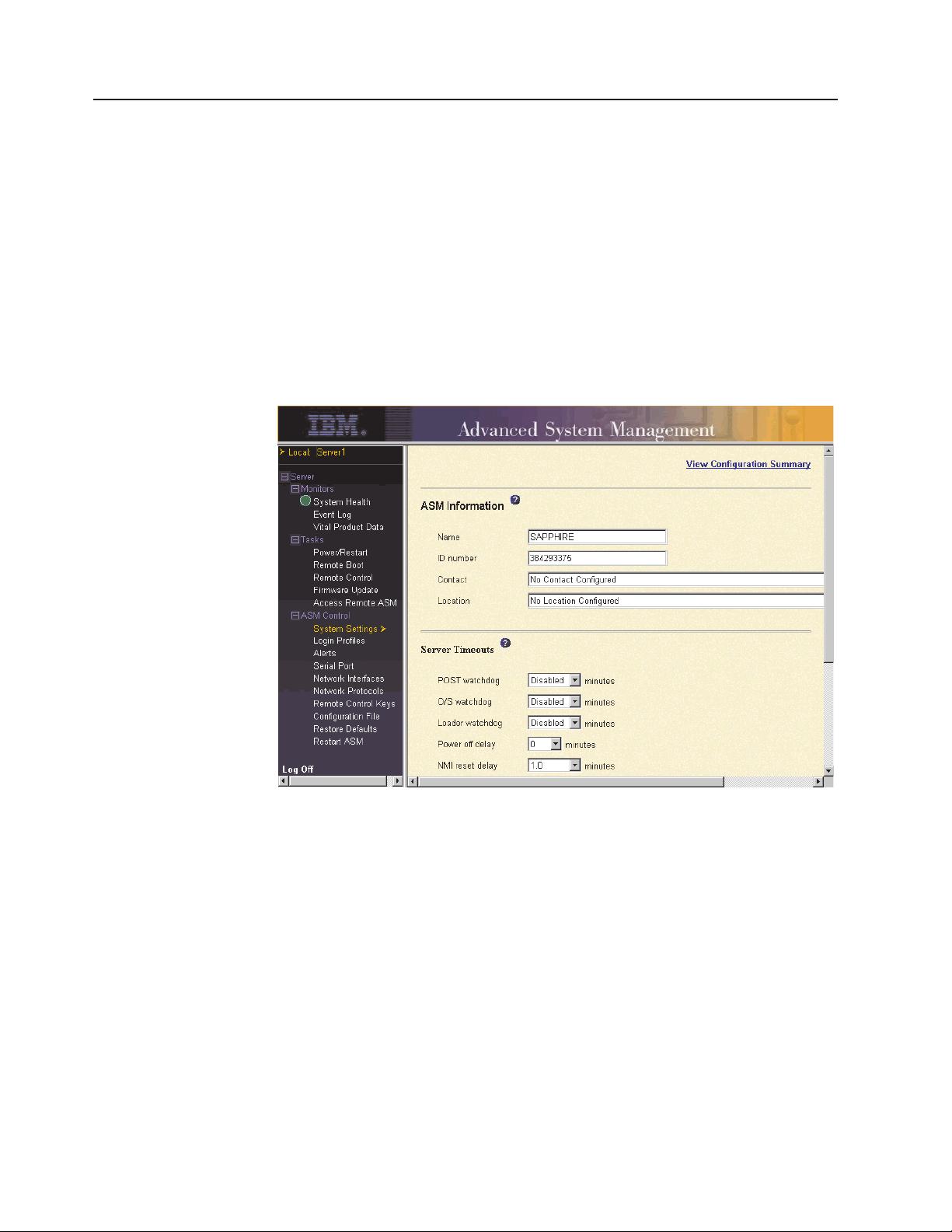
2. In the navigation pane, click System Settings. A window similar to the one in
the following illustration opens.
Note: The available fields in the System Settings page are determined by the
accessed remote server.
3. In the Name field in the ASM Information section, type the name of the Remote
Supervisor Adapter or ASM processor.
Use the Name field to specify a name for the Remote Supervisor Adapter in this
server. The name is included with e-mail, SNMP, and alphanumeric pager alert
notifications to identify the source of the alert.
Note: Your Remote Supervisor Adapter name (in the Name field) and the IP
host name of the Remote Supervisor Adapter (in the Host Name field on
the Network Interfaces page) do not automatically share the same name
because the ASM Name field is limited to 15 characters. The Host
Name field can consist of up to 63 characters. To minimize confusion, set
the ASM Name field to the nonqualified portion of the IP host name. The
nonqualified IP host name consists of up to the first period of a fully
qualified IP host name. For example, for the fully qualified IP host name
asmcard1.us.company.com, the nonqualified IP host name is asmcard1.
For information about your host name, see “Configuring an Ethernet
connection to the Remote Supervisor Adapter” on page 34.
14 Remote Supervisor Adapter: User’s Guide
Page 21
4. In the ID number field, assign the Remote Supervisor Adapter a unique
identification number.
5. In the Contact field, type the contact information. For example, you can specify
the name and phone number of the person to contact if there is a problem with
this server. You can type a maximum of 47 characters in this field.
Note: The Contact field is not available for all servers.
6. In the Location field, type the location of the server. Include in this field
sufficient detail to quickly locate the server for maintenance or other purposes.
You can type a maximum of 47 characters in this field.
Note: The Location field is not available for all servers.
7. Scroll to the bottom of the page and click Save.
Setting server timeouts
Complete the following steps to set your server timeout values:
1. Log in to the Remote Supervisor Adapter where you want to set the server
timeouts. For more information, see Chapter 2, “Opening and using the ASM
Web interface” on page 3.
2. For an xSeries 330 server: Log in to the ASM processor. For more information,
see “Logging in to the ASM processor in an xSeries 330 server” on page 6.
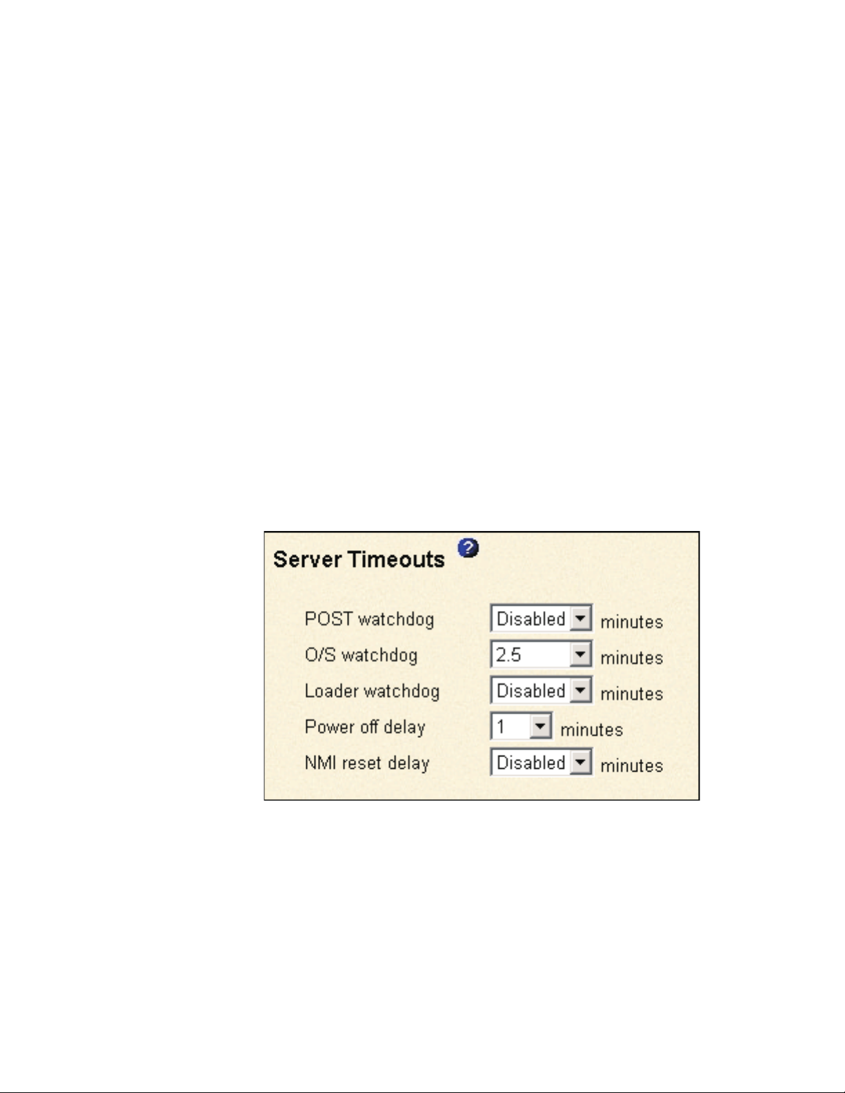
3. In the navigation pane, click System Settings and scroll down to the Server
Timeouts section.
A window similar to the one in the following illustration opens.
You can set the Remote Supervisor Adapter or ASM processor to respond
automatically to the following events:
v Halted power-on self-test
v Halted operating system
v Failure to load operating system
v Power off delay to shut down operating system
v nonmaskable interrupt
4. Enable the server timeouts that correspond to the events you want the Remote
Supervisor Adapter to respond to automatically.
Chapter 3. Configuring your Remote Supervisor Adapter or ASM processor 15
Page 22

POST watchdog
Use the POST watchdog field to specify the number of minutes that the
Remote Supervisor Adapter or ASM processor will wait for this server to
complete a power-on self-test (POST). If the server being monitored
fails to complete a POST within the specified time, the Remote
Supervisor Adapter generates a POST timeout alert and automatically
restarts the server. The POST watchdog is then automatically disabled
until the operating system is shut down and the server is power cycled
(or until the operating system starts and the device driver successfully
loads).
Note: Power cycling differs from shutting down and restarting the
operating system in that power cycling removes power from the
server completely; for example, unplugging the server.
To set the POST timeout value, select a number from the menu. To turn
off this option, select Disabled.
Note: If the POST Time-out check box is selected in the Remote Alerts
section of the Remote Alerts page, the Remote Supervisor
Adapter or ASM processor attempts to forward the alert to all
configured remote alert recipients. Also, the POST watchdog
requires a specially constructed POST routine available on only
specific IBM servers. If this routine does not exist on your server,
all settings in this field are ignored.
O/S watchdog
Use the O/S watchdog field to specify the number of minutes between
checks of the operating system by the Remote Supervisor Adapter or
ASM processor. If the operating system fails to respond to one of these
checks, the Remote Supervisor Adapter or ASM processor generates an
O/S timeout alert and restarts the server. After the server is restarted,
the O/S watchdog is disabled until the operating system is shut down
and the server is power cycled.
To set the O/S watchdog value, select a time interval from the menu. To
turn off this watchdog, select Disabled. To capture blue screens, you
must enable the watchdog in the O/S watchdog field and select the
O/S Time-out check box in the Remote Alerts section of the Alerts
page.
Notes:
a. The O/S watchdog feature requires that the Remote Supervisor
Adapter device driver is installed on the server. For information
about installing device drivers, see the Remote Supervisor Adapter
Installation Guide .
b. If the O/S Time-out check box is selected in the Remote Alerts
section of the Alerts page, the Remote Supervisor Adapter will
attempt to send an alert to all configured remote alert recipients.
For more information about POST routines, see the
documentation that comes with your server.
Loader watchdog
Use the Loader watchdog field to specify the number of minutes that
the Remote Supervisor Adapter or ASM processor waits between the
completion of POST and the starting of the operating system. If this
16 Remote Supervisor Adapter: User’s Guide
Page 23

interval is exceeded, the Remote Supervisor Adapter or ASM processor
generates a loader timeout alert and automatically restarts the system.
After the system is restarted, the loader timeout is automatically
disabled until the operating system is shut down and the server is
power cycled (or until the operating system starts and the device driver
successfully loads).
To set the loader timeout value, select the time limit that the Remote
Supervisor Adapter or ASM processor will wait for operating-system
starting to be completed. To turn off this watchdog, select Disabled.
Note: If the Loader Time-out check box is selected in the Remote
Power off delay
Attention: Read the following information to prevent the loss of data
or damage to data when you perform a remote shutdown of your
operating system:
a. If the Windows 2000, Windows NT
operating system is installed on your server, you need to install only
the Remote Supervisor Adapter device driver to support remote
operating-system shutdown.
Alerts section of the Alerts page, the Remote Supervisor Adapter
or ASM processor will send an alert to all configured remote alert
recipients.
®
, Red Hat Linux, or SuSE Linux
Note: If the value is less than 45 seconds in the Power off delay
field, the device driver will adjust the value to 45 seconds
when the device driver loads. You can decrease the
power-off delay value after the server has started, but the
device driver will reset it to 45 seconds on the next server
restart. The device driver will not change a power-off delay
value that is 45 seconds or greater.
b. If the Novell NetWare, SCO UnixWare, or Caldera Open UNIX
®
operating system is installed on your server, you need to install both
the Remote Supervisor Adapter device driver and IBM Director
Agent, to support remote operating system shutdown. When you
install the Director Agent, be sure to select the Management
Processor Assistant (MPA) check box.
Use the Power off delay field to specify the number of minutes that the
Remote Supervisor Adapter or ASM processor will wait for the operating
system to shut down before turning off the server. By default, the
Remote Supervisor Adapter waits 30 seconds.
Shut down your server to determine how long it takes to shut down. Add
a time buffer to that value and use it as your power off delay setting to
ensure that the operating system has time for an orderly shutdown
before power is removed from the server.
To set the power-off delay value, select the time from the menu.
NMI reset delay
Use the NMI reset delay field to specify the length of time, in minutes,
that the Remote Supervisor Adapter waits to automatically restart the
server after a nonmaskable interrupt (NMI) is triggered. A nonmaskable
Chapter 3. Configuring your Remote Supervisor Adapter or ASM processor 17
Page 24

interrupt usually indicates a critical error such as a hardware fault. A
nonmaskable interrupt usually signals a parity error in the memory
subsystem.
To disable the automatic server restart after a nonmaskable interrupt,
select Disabled .
Note: The NMI reset delay field is not available on all servers.
5. Scroll to the bottom of the page and click Save.
Setting the date and time
The Remote Supervisor Adapter and ASM processor each contain their own
real-time clocks to independently time stamp all events that are logged in the
battery-backed event logs. Setting one clock does not affect the settings of the
other clock, and each clock serves a separate purpose.
Alerts sent by e-mail, LAN, and SNMP use the real-time clock setting to time stamp
the alerts. The clock settings support Greenwich mean time (GMT) offsets and
daylight saving time (DST) for added ease-of-use for administrators managing
systems remotely over different time zones. You can remotely access the
battery-backed event log even if the system is turned off or disabled. This facilitates
immediate problem determination and resolution.
Note: The GMT offset and AutomaticaIly adjust for daylight saving changes
fields are not available when you are logged in to an ASM processor or ASM
PCI adapter.
Complete the following steps to verify the date and time settings of the Remote
Supervisor Adapter or ASM processor:
1. Log in to the Remote Supervisor Adapter where you want to set the ASM date
and time values. For more information, see Chapter 2, “Opening and using the
ASM Web interface” on page 3.
2. For an xSeries 330 server: If you want to set the date and time values for the
ASM processor, log in to the ASM processor. For more information, see
“Logging in to the ASM processor in an xSeries 330 server” on page 6.
3. In the navigation pane, click System Settings and scroll down to the ASM Date
and Time section, which shows the date and time when this Web page was
generated.
4. To override the date and time settings and to enable daylight saving time (DST)
and Greenwich Mean Time (GMT), click Set ASM Date and Time. A window
18 Remote Supervisor Adapter: User’s Guide
Page 25
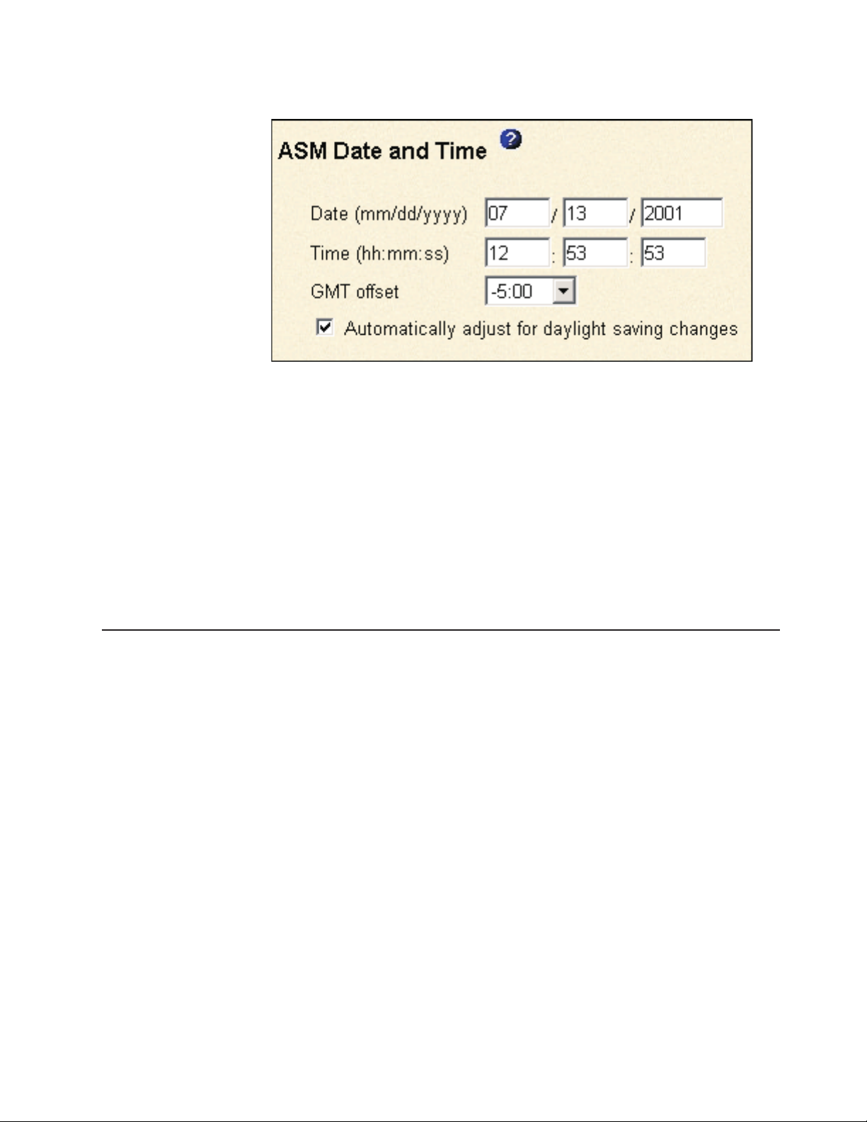
similar to the one in the following illustration opens.
5. In the Date field, type the numbers of the current month, day, and year in the
matching entry fields.
6. In the Time field, type the numbers corresponding to the current hour, minutes,
and seconds in the appropriate entry fields. The hour (hh) must be a number
from 00 to 23 as represented on a 24-hour clock. The minutes (mm) and
seconds (ss) must be numbers from 00 to 59.
7. In the GMT offset field, type the number that specifies the offset in hours from
Greenwich Mean Time (GMT), corresponding to the time zone where this server
is located.
8. Click the Automatically adjust for daylight saving changes check box to
specify whether the Remote Supervisor Adapter clock will automatically adjust
when the local time changes between standard time and daylight saving time.
9. Scroll to the bottom of the page and click Save.
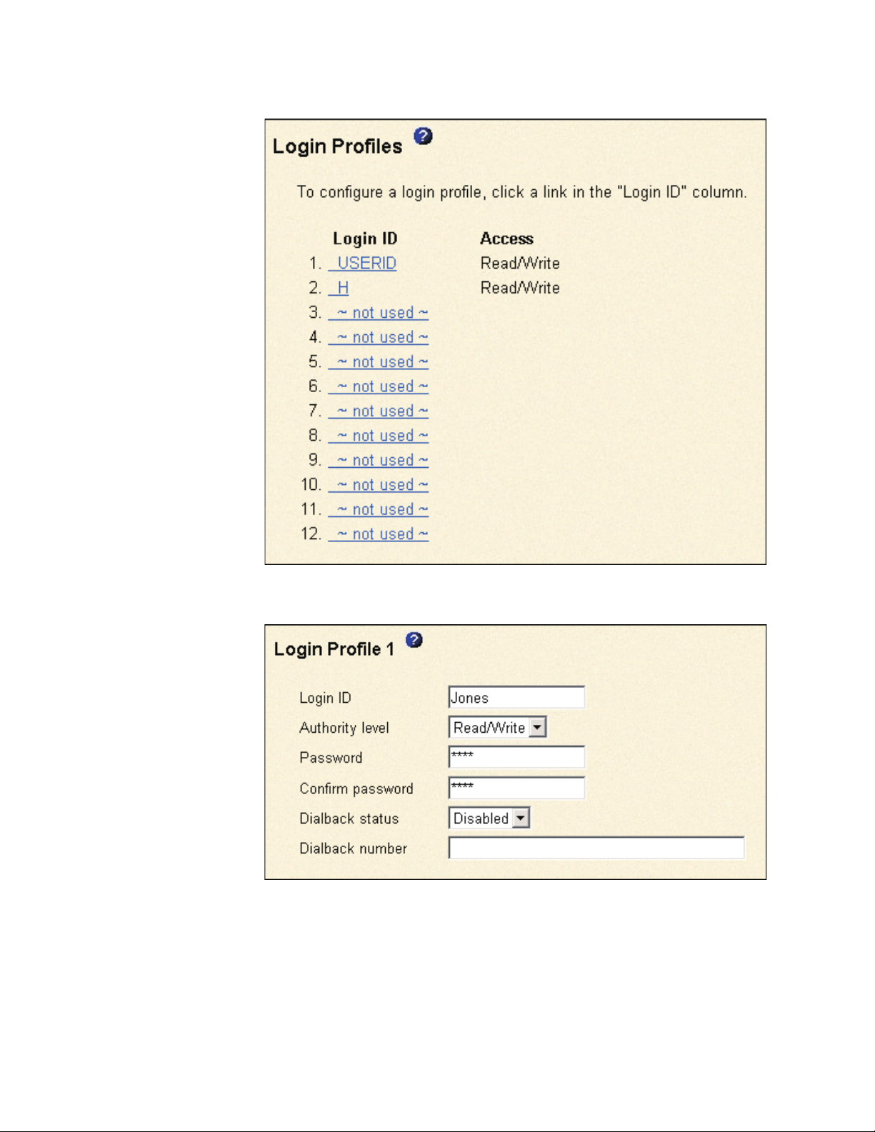
Creating a login profile
Use the Login Profiles table to view, configure, or change individual login profiles.
Use the links in the Login ID column to configure individual login profiles. You can
define up to 12 unique profiles. Each link in the Login ID column is labeled with the
configured login ID for that particular profile. If you have not configured a profile, the
name of the link by default will be ~ not used ~.
Complete the following steps to configure a login profile:
1. Log in to the Remote Supervisor Adapter where you want to create a login
profile. For more information, see Chapter 2, “Opening and using the ASM
Web interface” on page 3.
2. For an xSeries 330 server: If you want to create a login profile on the ASM
processor, log in to the ASM processor. For more information, see “Logging in
to the ASM processor in an xSeries 330 server” on page 6.
3. In the navigation pane, click Login Profiles. The Login Profiles page displays
the login ID and the login access level. A window similar to the one in the
Chapter 3. Configuring your Remote Supervisor Adapter or ASM processor 19
Page 26
following illustration opens.
4. Click one of the unused login profile links. An individual profile window similar
to the one in the following illustration opens.
5. In the Login ID field, type the name of the profile.
You can type a maximum of 15 characters in the Login ID field. Valid
characters are uppercase and lowercase letters, numbers, periods, and
underscores.
Note: This login ID is used to grant remote access to the Remote Supervisor
Adapter or ASM processor.
20 Remote Supervisor Adapter: User’s Guide
Page 27

6. In the Authority level field, select either Read Only or Read/Write to set the
access rights for this login ID.
Read Only
The user can use the Read Only option to view a window, but not to
make changes. Additionally, users who log in with read-only IDs are
unable to perform file transfers, power and restart actions, or remote
control functions.
Read/Write
The user can use the Read/Write option to take all available actions
provided by the interface, including setting up a user ID and turning off
the server.
7. In the Password field, assign a password to the Login ID.
Valid passwords must contain at least five characters, one of which must be a
nonalphabetic character. Null or empty passwords are accepted.
Note: This password is used with the login ID to grant remote access to the
Remote Supervisor Adapter or ASM processor.
8. In the Confirm Password field, type the password again.
9. In the Dialback status field, select Enabled or Disabled to configure the
Remote Supervisor Adapter or ASM processor to automatically terminate a
successful dial-in attempt and then immediately dial out to a specified number.
If you select Disabled, click Save to save your login ID settings.
Note: If the Dialback status field is set to Enabled, you must enter a phone
number in the Dialback number field of this profile.
10. In the Dialback number field, type the phone number that the Remote
Supervisor Adapter will use when dialing back to reach the login ID. This
phone number is dialed when this user successfully logs in to the Remote
Supervisor Adapter.
Note: By default, the Remote Supervisor Adapter and ASM processor are
each configured with one login profile that enables remote access using
a login user ID of USERID and a password of PASSW0RD (the 0 is a
zero). To avoid a potential security exposure, change this default login
profile during the initial setup of the Remote Supervisor Adapter or ASM
processor.
11. Click Save to save your login ID settings.
Setting the global login settings
Complete the following steps to enable your modem to dial out to the remote login
profile:
1. Log in to the Remote Supervisor Adapter for which you want to set the global
login settings. For more information, see Chapter 2, “Opening and using the
ASM Web interface” on page 3.
2. For an xSeries 330 server: If you want to set the modem and dial-in settings
on the ASM processor, log in to the ASM processor. For more information, see
“Logging in to the ASM processor in an xSeries 330 server” on page 6.
3. In the navigation pane, click Login Profiles.
4. Scroll down to the Global Login Settings section.
Chapter 3. Configuring your Remote Supervisor Adapter or ASM processor 21
Page 28

5. To allow remote users to dial in to the Remote Supervisor Adapter or ASM
processor through a serial connection, select Enabled in the Logins through a
modem connection field.
6. In the Lockout period after five login failures field, specify how long, in
minutes, the Remote Supervisor Adapter or ASM processor will prohibit remote
login attempts, if more than five sequential failures to log in remotely are
detected.
Configuring remote alert settings
You can configure remote alert recipients, the number of alert attempts, incidents
that trigger remote alerts, and local alerts from the Alerts link on the navigation
pane.
After you configure a remote alert recipient, the Remote Supervisor Adapter or ASM
processor will send an alert to that recipient. The alert is sent through a serial
connection or a network connection, a numeric pager, or an alphanumeric pager
when any event selected from the Monitored Alerts group occurs. This alert
contains information about the nature of the event, the time and date of the event,
and the name of the system that generated the alert.
The Remote Supervisor Adapter or ASM processor offers alert redundancy for
several managed systems at the same location. It sends alerts only once per
connection type, even when there is more than one active LAN or serial connection.
However, if one connection device fails, all other interconnected devices route the
alerts to the next available connection.
Notes:
1. If the SNMP Agent or SNMP Traps fields are not set to Enabled, no SNMP
traps are sent. For information about these fields, see “Configuring SNMP” on
page 38.
2. You cannot distinguish between the alerts that are sent to remote alert
recipients. All configured recipients receive each alert you select.
3. The Remote Supervisor Adapter cannot generate alerts; it can only forward the
alerts that are generated by the ASM processor on an xSeries 330 server or
that are generated by other devices on the same ASM interconnect network.
4. For an xSeries 330 server, you must log in to the ASM processor to configure
alert recipients, global alert settings, and incidents that trigger remote alerts and
local events.
5. If the ASM processor cannot send out the alert, it forwards the alert to the
Remote Supervisor Adapter. SNMP over LAN and IBM Director over LAN alerts
are always forwarded by the ASM processor because it does not have LAN
connectivity. For SNMP alerts, the configuration of the SNMP agent has to be
done on the Remote Supervisor Adapter. For more information about these
fields, see “Configuring SNMP” on page 38.
Configuring remote alert recipients
You can define up to 12 unique remote alert recipients. Each link for an alert
recipient is labeled with the recipient name, notification method, and alert status.
Complete the following steps to configure a remote alert recipient:
1. Log in to the Remote Supervisor Adapter for which you want to configure
remote alert settings. For more information, see Chapter 2, “Opening and using
the ASM Web interface” on page 3.
22 Remote Supervisor Adapter: User’s Guide
Page 29
2. For an xSeries 330 server: If you want to configure a remote alert recipient
on the ASM processor, log in to the ASM processor. For more information, see
“Logging in to the ASM processor in an xSeries 330 server” on page 6.
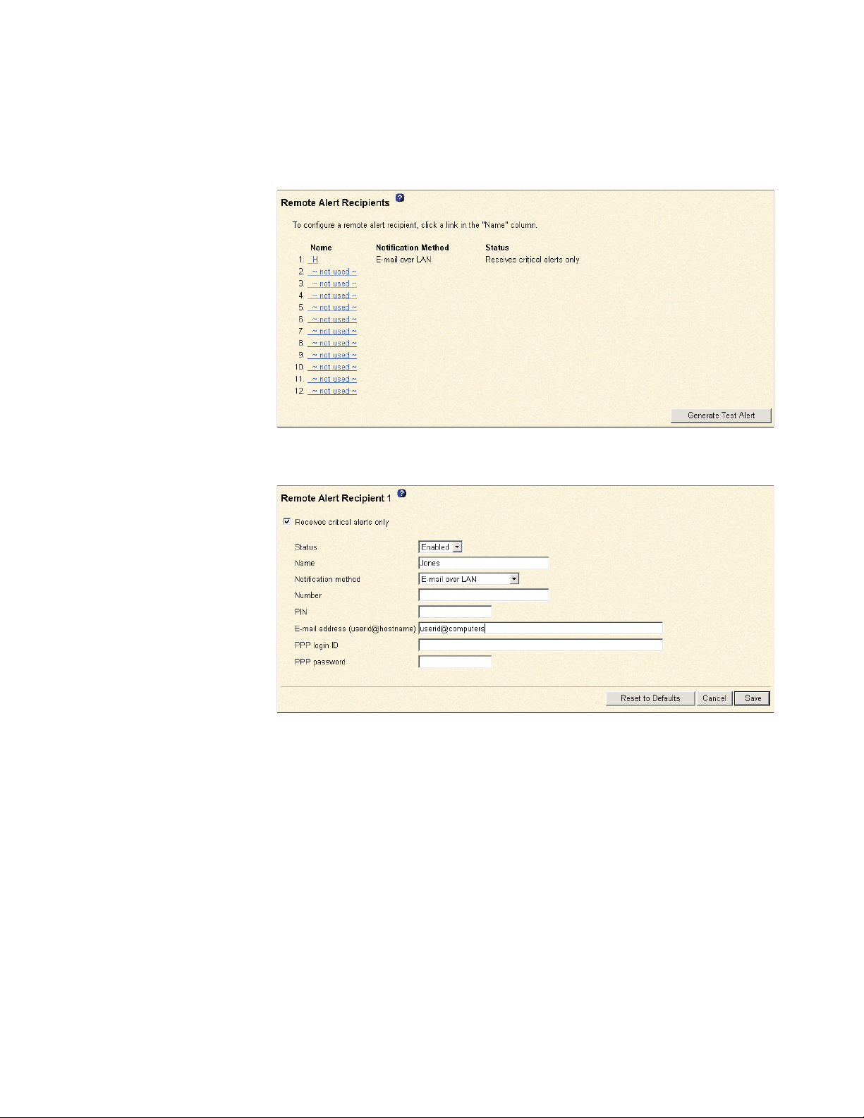
3. In the navigation pane, click Alerts. The Remote Alert Recipients page opens.
You can see the notification method and alert status, if set, for each recipient.
4. Click one of the remote alert recipient links. An individual recipient window
similar to the one in the following illustration opens.
5. To have only critical alerts sent to the recipient, select the Receives critical
alerts only check box.
6. In the Status field, click Enabled to activate this remote alert recipient.
7. In the Name field, type the name of the recipient or other identifier. The name
you enter appears as the link for the recipient on the Alerts page.
8. In the Notification method field, select the notification method for reaching
the recipient. Select one of the following notification methods. Not all methods
are available on all servers.
v Numeric pager
v Alphanumeric pager
v IBM Director over Modem
v IBM Director over LAN
v SNMP over LAN
v E-mail over LAN
v SNMP over PPP
v E-mail over PPP
Chapter 3. Configuring your Remote Supervisor Adapter or ASM processor 23
Page 30

Notes:
a. To configure a remote alert recipient for IBM Director over Modem or IBM
Director over LAN, the remote alert recipient must be a server with the
Director Management Server installed.
b. The IBM Director over Modem option is supported in only IBM Director
versions 2.2.1, 3.1, and 3.1.1.
9. In the Number field, type either the phone number, IP address, or host name
at which to reach the recipient. Type a phone number if you are using one of
the following notification methods:
v Numeric pager (follow the phone number with a comma and the personal
identification number [PIN])
v Alphanumeric pager
v IBM Director over Modem
v SNMP over PPP
v E-mail over PPP
Type an IP address or host name if you are using the IBM Director over LAN
method.
10. If you chose alphanumeric pager as the notification method, in the PIN field,
enter the PIN.
11. If you selected the E-mail over LAN or E-mail over PPP notification methods, in
the E-Mail address field, type the e-mail address of the recipient.
Note: For the E-mail over LAN and E-mail over PPP notification methods to
work properly, configure the Simple Mail Transfer Protocol (SMTP)
options on the Network Protocols page. For more information about
SMTP options, see “Configuring SMTP” on page 41.
12. If you selected the E-mail over PPP or SNMP over PPP notification methods,
at the PPP login ID field, type the PPP login ID needed to log in to the dial-up
service account of the recipient. The PPP login ID consists of your service,
your account name, and your user ID all separated by periods
(service.account.userid).
®
For example, to log in to the IBM Global Network
IP Remote Access Service
Provider, the PPP login ID should contain information in the following format:
secureip.X.Y, where secureip is your service and X is your account name, and
Y is your user ID.
Notes:
a. For the SNMP over LAN and SNMP over PPP notification methods to work
properly, configure the SNMP options on the Network Protocols page. For
information about SNMP, see “Configuring SNMP” on page 38.
b. For an xSeries 330 server: SNMP over LAN and IBM Director over LAN
alerts are always forwarded because the ASM processor does not have
LAN connectivity.
13. If you selected the E-mail over PPP or SNMP over PPP notification method, at
the PPP password field, type the PPP password that accompanies the login
ID.
14. Click Save to save your remote alert recipient profile. Repeat step 3 on
page 23 through step 13 on page 24 for each remote alert recipient profile.
15. Click Generate Test Alert on the Remote Alert Recipients page to send a test
alert to all configured remote alert recipients.
24 Remote Supervisor Adapter: User’s Guide
Page 31

Forwarding alerts
The Alert Forwarding setting applies only to alerts forwarded from the integrated
system management processor (ISMP) on an ASM interconnect network. The
ISMPs on the network forward alerts to only the Remote Supervisor Adapter that is
designated as the gateway. A Remote Supervisor Adapter is a gateway to the
interconnect network if:
v On the Alerts Forwarding page, you click Make this ASM the Gateway.
v If none of the Remote Supervisor Adapters on the network are configured by a
Notes:
1. There has to be at least one Remote Supervisor Adapter on the interconnect
2. At any time, only one Remote Supervisor Adapter can be the gateway on an
3. When a user configures a Remote Supervisor Adapter to be the gateway, any
4. The remote alert recipients and monitored alerts for the ISMPs on the
Note: All selected alert events are sent to all configured remote alert
recipients.
user to be the gateway, the Remote Supervisor Adapters on the network
negotiate and designate one Remote Supervisor Adapter to be the gateway.
network for ISMP alerts to be forwarded.
interconnect network.
existing gateway (user defined or negotiated) ceases to be the gateway.
interconnect network have to be configured on the gateway Remote Supervisor
Adapter.
Complete the following steps to verify whether the selected Remote Supervisor
Adapter is the gateway to the interconnect network:
1. Log in to the Remote Supervisor Adapter for which you want to see the alert
forwarding status. For more information, see Chapter 2, “Opening and using the
ASM Web interface” on page 3.
2. In the navigation pane, click Alerts and scroll down to the Alert Forwarding
section:
3. The Status field shows whether the Remote Supervisor Adapter is the gateway,
and if it is, whether it is a user configured or negotiated gateway. The possible
values are:
v Not a gateway for ISMPs
v User configured gateway for ISMPs
v Negotiated gateway for ISMPs
Setting remote alert attempts
When you are logged in to the Remote Supervisor Adapter, the remote alert
attempts settings apply only to forwarded alerts. When you are logged in to the
ASM processor, the remote alert attempts settings apply to the alerts generated by
the ASM processor.
Chapter 3. Configuring your Remote Supervisor Adapter or ASM processor 25
Page 32

Complete the following steps to set the number of times the Remote Supervisor
Adapter or ASM processor attempts to send an alert:
1. Log in to the Remote Supervisor Adapter on which you want to set remote alert
attempts. For more information, see Chapter 2, “Opening and using the ASM
Web interface” on page 3.
2. For an xSeries 330 server: If you want to set the remote alert attempts on the
ASM processor, log in to the ASM processor. For more information, see
“Logging in to the ASM processor in an xSeries 330 server” on page 6.
3. In the navigation pane, click Alerts and scroll down to the Global Remote Alert
Settings section.
Use these settings to define the number of remote alert attempts and the time
between the attempts. The settings apply to all configured remote alert
recipients.
Remote alert retry limit
Use the Remote alert retry limit field to specify the number of
additional times that the Remote Supervisor Adapter or ASM processor
will attempt to send an alert to a recipient.
Delay between retries
4. Select the Include event log with e-mail alerts check box to attach the local
event log to all e-mail alert notifications. The event log provides a summary of
the most recent events and assists with problem identification and fast recovery.
Notes:
a. To send the event log as an e-mail attachment, you must select E-mail over
b. Event logs attached in an e-mail are not forwarded to a Remote Supervisor
5. Scroll to the bottom of the page and click Save.
Setting remote alerts
Note: For an xSeries 330 server: You can set remote alerts only when you are
Complete the following steps to select the remote alerts to be sent:
1. Log in to the Remote Supervisor Adapter where you want to set remote alerts.
For more information, see Chapter 2, “Opening and using the ASM Web
interface” on page 3.
Use the Delay between retries field to specify the time interval (in
minutes) that the Remote Supervisor Adapter or ASM processor will wait
between retries to send an alert to a recipient.
LAN or E-mail over PPP as the notification method for at least one remote
alert recipient.
Adapter on the ASM interconnect network.
logged in to the ASM processor.
26 Remote Supervisor Adapter: User’s Guide
Page 33

2. For an xSeries 330 server: To set the remote alert attempts on the ASM
processor, log in to the ASM processor. For more information, see “Remote
Supervisor Adapter and ASM processor action descriptions” on page 7.
3. In the navigation pane, click Alerts and scroll down to the Monitored Alerts
section.
4. Select the events you want the Remote Supervisor Adapter or ASM processor
to monitor.
The remote alerts are categorized by the following levels of severity:
v Critical
v Warning
v System
All alerts are stored in the event log and sent to all configured remote alert
recipients.
Critical alerts
Critical alerts are generated for events that signal that the server is no
longer functioning. If the Select all critical alerts check box is selected,
an alert can be sent for any critical alert.
Table 3. Critical remote alerts
Alphanumeric
pager code
00 Temperature irregularity Generates an alert if any of the monitored temperatures are outside
01 Voltage irregularity Generates an alert if the voltages of any of the monitored power supplies
02 Tampering Generates an alert if physical intrusion of the server box is detected.
03 Multiple fan failure Generates an alert if two or more of the cooling fans in the server fail.
04 Power failure Generates an alert if any of the server power supplies fail.
05 Hard disk drive failure Generates an alert if one or more of the hard disk drives in the server
06 VRM failure Generates an alert if one or more voltage regulator modules (VRMs) fail.
07-09 Reserved for future use.
Event Action
critical threshold values. To view the threshold values, click the
temperature readings on the System Health page. If a critical
temperature condition is detected, the server shuts down and turns off,
regardless of the alert notification setting.
fall outside their specified operational ranges. To view the operational
ranges, click the voltage readings on the System Health page. If a critical
voltage condition is detected, the server shuts down and turns off,
regardless of the alert notification setting.
Tamper monitoring is not available on some servers, in which case this
setting is ignored.
fail.
This setting is ignored for servers without VRMs.
Warning alerts
Warning alerts are generated for events that might progress to a
critical/error level. If the Select all warning alerts check box is
selected, an alert can be sent for any warning alert.
Chapter 3. Configuring your Remote Supervisor Adapter or ASM processor 27
Page 34

Table 4. Warning remote alerts
Alphanumeric
pager code
10 Redundant power
11 Single fan failure Generates an alert if one fan fails.
12 Temperature irregularity Generates an alert if any monitored temperatures are outside the
13 Voltage irregularity Generates an alert if any monitored voltages are outside the warning
14 - 19 Reserved for future use.
Event Action
Generates an alert if a redundant power supply fails.
supply failure
warning threshold values. To access these temperature threshold values,
click the temperature readings on the System Health page. Unlike the
critical temperature event, this event will not initiate a server shutdown.
threshold values. To access these voltage range values, click the voltage
readings on the System Health page. Unlike the critical voltage event,
this event will not initiate an automatic server shutdown.
System alerts
System alerts are generated for events that occur as a result of system
errors. If the Select all system alerts check box is selected, an alert
can be sent for any system alert.
Notes:
a. The Select all system alerts check box is not available on all
servers.
®
b. Hard disk drive Predictive Failure Analysis
(PFA) alerts are not
monitored.
Table 5. System remote alerts
Alphanumeric
pager code
20 POST timeout Generates an alert if an enabled POST timeout value is exceeded. The
21 O/S timeout Generates an alert if an enabled operating system timeout value is
22 Test alert Generates an alert if the Generate Test Alert button is clicked on the
23 Power off Generates an alert if the server is turned off.
24 Power on Generates an alert if the server is turned on.
25 Boot failure Generates an alert if an error occurs that prevents the server from
26 Loader timeout Generates an alert if an enabled server loader timeout value is
27 PFA notification Generates an alert if a PFA notification is generated by the server
28 - 29 Reserved for future use.
Event Action
POST timeout value is configured in the Server Timeouts section on the
System page.
exceeded. The operating system timeout value is configured in the
Server Timeouts section on the System page. The O/S timeout alert
must be checked to enable remote blue screen capture.
Remote Alert Recipients page.
starting.
exceeded. The system loader timeout value is configured in the Server
Timeouts section on the System page.
hardware. This feature is available only on server that have PFA-enabled
hardware.
5. Scroll to the bottom of the page and click Save.
28 Remote Supervisor Adapter: User’s Guide
Page 35

Setting local events
Complete the following steps to select the local events to which the Remote
Supervisor Adapter or ASM processor will respond:
1. Log in to the Remote Supervisor Adapter where you want to set local events.
For more information, see Chapter 2, “Opening and using the ASM Web
interface” on page 3.
2. For an xSeries 330 server: Log in to the ASM processor. For more information,
see “Remote Supervisor Adapter and ASM processor action descriptions” on
page 7.
3. In the navigation pane, click Alerts and scroll down to the Monitored Local
Events section.
4. Select the events that you want to store in the event log. The Remote
Supervisor Adapter and ASM processor store the notification only in the event
log.
Local events are generated for events sent to IBM Director, if it is installed, on
the server where the ASM subsystem resides. These events are not sent to
remote alert recipients. If the Select all local events check box is selected, an
alert can be sent for any local event.
Table 6. Local events
Event Action
Event log 75% full Generates a local notification if the event log reaches 75% of
Voltage irregularity Generates a local notification if any of the monitored voltages
Power off Generates a local notification if the server is powered off.
Power supply failure Generates a local notification if a power supply failure is
Event log full Generates a local notification if the event log reaches its
Redundant power supply
failure
Tampering Generates a local notification if the server covers are removed.
DASD failure Generates a local notification if any hard disk drive failures are
Remote login Generates a local notification if a remote login occurs.
Temperature irregularity Generates a local notification if any of the monitored
Fan failure Generates a local notification if one or more cooling fans fail.
PFA notification Generates a local notification if any of the hardware in the
capacity.
exceed their thresholds.
detected.
capacity. At capacity, the oldest events are deleted.
Generates a local notification if the redundant power supply
fails.
This feature is only available on some servers.
detected.
temperatures exceed thresholds.
server generates a PFA event.
5. Scroll to the bottom of the page and click Save.
Configuring the serial port
You can either dedicate the integrated serial port on the Remote Supervisor Adapter
to system management or share it with the server operating system. If dedicated to
system management, the serial port serves only the Remote Supervisor Adapter
and is always available for dial-in and dial-out alerting purposes. You will not be
Chapter 3. Configuring your Remote Supervisor Adapter or ASM processor 29
Page 36

able to monitor the serial port in the operating system or in any other applications.
This design enables a single serial port to conduct normal functions and also
maintain out-of-band alerting capabilities.
Notes for an xSeries 330 server:
1. The ASM processor on an xSeries 330 server uses the two serial ports on the
rear of your server. One of these serial ports can be shared with the server
operating system while the other is dedicated to the ASM processor.
2. You can configure the serial ports on either the Remote Supervisor Adapter or
the ASM processor, depending on which device you are using.
For more information about your serial port, see “Configuring PPP access over a
serial port” on page 36. Configuring PPP access over a serial port only applies to
the Remote Supervisor Adapter.
Complete the following steps to configure your serial port:
1. Log in to the Remote Supervisor Adapter on which you want to configure the
serial port. For more information, see Chapter 2, “Opening and using the ASM
Web interface” on page 3.
2. For an xSeries 330 server: To configure the serial ports on the ASM
processor, log in to the ASM processor. For more information, see “Logging in
to the ASM processor in an xSeries 330 server” on page 6.
3. In the navigation pane, click Serial Port. If you are logged in to the Remote
Supervisor Adapter, a window similar to the one in the following illustration
opens.
30 Remote Supervisor Adapter: User’s Guide
Page 37

If you are logged in to the ASM processor, a window similar to the one in the
following illustration opens.
Note: Only Serial Port 1 appears on the Serial Port page when you are
logged in to the Remote Supervisor Adapter.
4. In the Baud rate field, select the data-transfer rate.
Use the Baud rate field to specify the data-transfer rate of your serial port
connection. To set the baud rate, select the data-transfer rate, in bits per
second, that corresponds to your serial port connection.
5. In the Parity field, select the error detection to be used in your serial
connection.
6. Select the number of data-terminating 1-bits in the Stop bits field that will
follow the data or any parity bit to mark the end of a transmission (normally a
byte or character).
Note: The number of data bits is preset to 8 and cannot be changed.
7. If you are logged in to a Remote Supervisor Adapter installed in a non-xSeries
330 server: Select the Dedicate to ASM check box to reserve the serial port
for the Remote Supervisor Adapter.
When shared with the operating system, the serial port serves the Remote
Supervisor Adapter only while the server is turned off or during the power-on
self-test (POST). The operating system can access it after the POST is
completed. The Remote Supervisor Adapter takes over the serial port from the
operating system to dial out and transmit an alert only after a critical event.
The port then remains under Remote Supervisor Adapter control until the
server is restarted.
Note: If you have configured a PPP interface, you must dedicate the serial
port to the Remote Supervisor Adapter, or you will lose the PPP port
when the host restarts.
Chapter 3. Configuring your Remote Supervisor Adapter or ASM processor 31
Page 38

8. If you are logged in to an ASM processor: Select the Dedicate to ASM
check box to reserve serial port 1 for the ASM processor. This option is
displayed only when you are logged in to an ASM processor.
If shared with the operating system, the serial port serves the ASM processor
only when the server is turned off or during the power-on self-test (POST). The
operating system can access it after the POST is completed. The ASM
processor takes over the serial port from the operating system to dial out and
transmit an alert only after a critical event. The port then remains under ASM
processor control until the server is restarted.
9. Click Save.
10. If you need to set advanced settings, click Advanced Modem Settings.A
window similar to the one in the following illustration opens.
Set these values only if the alert forwarding functions are not working properly.
The strings marked with an asterisk (*) require a carriage return (^M) to be
manually entered at the end of the field value.
The following table describes the initialization strings for this modem.
Table 7. Port 1 settings
Field What you type
Initialization
string
Dial prefix string Type the initialization string that is used before the number to be dialed.
32 Remote Supervisor Adapter: User’s Guide
Type the initialization string that will be used for the specified modem. A
default string is provided (ATE0). Do not change this string unless your
dial-out functions are not working properly.
The default is ATDT.
Page 39

Table 7. Port 1 settings (continued)
Field What you type
Hangup string Type the initialization string that will be used to instruct the modem to
disconnect. A default string is provided (ATH0). Do not change this string
unless your dial-out functions are not working properly.
Dial postfix string Type the initialization string that is used after the number is dialed to tell
the modem to stop dialing. The default is ^M.
Modem query Type the initialization string that is used to find out if the modem is
attached. The default is AT.
Factory settings
string
Auto answer Type the initialization string that is used to tell the modem to answer the
Escape string Type the initialization string that returns the modem to command mode
Auto answer
stop
Caller ID string Type the initialization string that will be used to get caller ID information
Escape guard (0
- 250)
Type the initialization string that returns the modem to its factory settings
when the modem is initialized. The default is AT&F0.
phone when it rings. The default is to answer after one ring or ATS0=1.
when it is currently talking to another modem. The default is +++.
Type the initialization string that is used to tell the modem to stop
answering the phone automatically when it rings. The default is ATS0=0.
from the modem.
Type the length of time before and after the escape string is issued to
the modem. This value is measured in 10 millisecond intervals. The
default value is 1 second.
11. Click Save.
Initialization-string guidelines
If you need to provide a new initialization string, see the documentation that came
with your modem. Your initialization string must contain commands that configure
your modem as follows:
v Command echoing OFF
v Online character echoing OFF
v Result codes ENABLED
v Verbal result codes ENABLED
v All codes and connect messages with BUSY and DT detection
v Protocol identifiers added — LAPM/MNP/NONE V42bis/MNP5
v Normal CD operations
v DTR ON-OFF hang-up, disable AA and return to command mode
v CTS hardware flow control
v RTS control of receive data to computer
v Queued and nondestructive break, no escape state
Note: The abbreviations in these commands have the following meanings:
AA auto answer
CD carrier detect
CTS clear to send
DT data transfer
DTR data terminal ready
LAPM link access protocol for modems
MNP microcom networking protocol
RTS ready to send
Chapter 3. Configuring your Remote Supervisor Adapter or ASM processor 33
Page 40

Configuring network interfaces
On the Network Interfaces page, you can set access to the Remote Supervisor
Adapter by:
v Configuring an Ethernet connection to a Remote Supervisor Adapter
v Configuring point-to-point protocol access over a serial port
Configuring an Ethernet connection to the Remote Supervisor Adapter
Complete the following steps to configure the Ethernet setup for the Remote
Supervisor Adapter:
1. Log in to the Remote Supervisor Adapter where you want to setup the
configuration. For more information, see Chapter 2, “Opening and using the
ASM Web interface” on page 3.
2. In the navigation pane, click Network Interfaces. A window similar to the one
in the following illustration opens.
Note: The values in the following window are examples. Your settings will be
different.
3. If you want to use an Ethernet connection, select Enabled in the Interface
field. Ethernet is enabled by default.
4. If you want to use a dynamic host configuration protocol (DHCP) server
connection, select Enabled in the DHCP field. DHCP is enabled by default.
Note: Do not enable DHCP unless you have an accessible, active, and
configured DHCP server on your network. When DHCP is enabled, the
automatic configuration will override any manual settings.
If DHCP is enabled, the host name is assigned as follows:
v If the Hostname field contains an entry, the Remote Supervisor Adapter
DHCP support will request the DHCP server to use this host name.
v If the Hostname field does not contain an entry, the Remote Supervisor
Adapter DHCP support will request the DHCP server to assign a unique
host name to the Remote Supervisor Adapter.
Go to step 12.
5. If DHCP is not enabled, type the IP host name of the Remote Supervisor
Adapter in the Hostname field.
34 Remote Supervisor Adapter: User’s Guide
Page 41

You can enter a maximum of 63 characters in this field, which represents the
IP host name of the Remote Supervisor Adapter. The host name defaults to
ASMA followed by the Remote Supervisor Adapter burned-in media access
control (MAC) address.
Note: The IP host name of the Remote Supervisor Adapter (the Hostname
field) and Remote Supervisor Adapter name (the ASM Name field on
the System page) do not automatically share the same name because
the ASM Name field is limited to 15 characters, but the Hostname field
can consist of up to 63 characters. To minimize confusion, set the ASM
Name field to the nonqualified portion of the IP host name. The
nonqualified IP host name consists of up to the first period of a fully
qualified IP host name. For example, for the fully qualified IP host name
asmcard1.us.company.com, the nonqualified IP host name is asmcard1.
For information about your host name, see “Setting system information”
on page 14.
6. In the IP address field, type the IP address of the Remote Supervisor Adapter.
You must do this only if DHCP is disabled. The IP address must contain:
v Four integers from 0 through 255 separated by periods
v No spaces
7. In the Subnet mask field, type the subnet mask used by the Remote
Supervisor Adapter. You must do this only if DHCP is disabled. The subnet
mask must contain:
v Four integers from 0 through 255 separated by periods
v No spaces or consecutive periods
The default setting is 255.255.255.0.
8. In the Gateway address field, type your network gateway router. You must do
this only if DHCP is disabled. The gateway address must contain:
v Four integers from 0 through 255 separated by periods
v No spaces or consecutive periods
9. Scroll to the bottom of the page and click Save.
10. Click Advanced Ethernet Setup if you need to set additional Ethernet
settings.
Chapter 3. Configuring your Remote Supervisor Adapter or ASM processor 35
Page 42

The following table describes the functions on the Advanced Ethernet page.
Table 8. Advanced Ethernet setup
Field Function
Data rate Use the Data Rate field to specify the amount of data to be transferred
per second over your LAN connection. To set the data rate, click the
menu and select the data-transfer rate in Mb
capability of your network. To automatically detect the data-transfer rate,
select Auto, which is the default value.
Duplex Use the Duplex field to specify the type of communication channel used
in your network.
To set the duplex mode, select one of the following:
Full enables data to be carried in both directions at once.
Half enables data to be carried in either one direction or the other, but
not both at the same time.
To automatically detect the duplex type, select Auto, which is the default
value.
Maximum
transmission unit
Burned-in MAC
address
Locally
administered
MAC address
1
Mb equals approximately 1 000 000 bits.
Use the Maximum transmission unit field to specify the maximum size
of a packet (in bytes) for your network interface. For Ethernet, the valid
maximum transmission unit (MTU) range is 60 - 1500. The default value
for this field is 1500.
The burned-in MAC address is a unique physical address assigned to
this Remote Supervisor Adapter by the manufacturer. The address is also
a read-only field.
Enter a physical address for this Remote Supervisor Adapter in the
Locally administered MAC address field. If a value is specified, the
locally administered address overrides the burned-in MAC address. The
locally administered address must be a hexadecimal value from
000000000000 through FFFFFFFFFFFF. This value must be in the form
XX:XX:XX:XX:XX:XX where X is a number between 0 and 9. The
Remote Supervisor Adapter does not support the use of a multicast
address. A multicast address has the least significant bit of the first byte
set to 1. The first byte, therefore, must be an even number.
1
that corresponds to the
11. Modify the advanced Ethernet settings as necessary.
12. Scroll to the bottom of the page and click Save.
13. Click Back to return to the Network Interfaces page.
14. If DHCP is enabled, the server automatically assigns the host name, IP
address, gateway address, subnet mask, domain name, DHCP server IP
address, and up to three DNS server IP addresses.
In order to view the DHCP server assigned setting, click IP Configuration
Assigned by DHCP Server.
15. Click Save.
16. In the navigation pane, click Restart ASM to activate the changes.
Configuring PPP access over a serial port
Use the point-to-point protocol (PPP) access method if you do not have Ethernet
access. You can use PPP through your serial port to enable access to the Remote
Supervisor Adapter through a Telnet session or a Web browser.
36 Remote Supervisor Adapter: User’s Guide
Page 43

Note: If you enable the PPP interface, the Remote Supervisor Adapter cannot use
the serial port for serial remote access.
Complete the following steps to configure PPP access over a serial port:
1. Log in to the Remote Supervisor Adapter where you want to configure PPP
access over a serial port. For more information, see Chapter 2, “Opening and
using the ASM Web interface” on page 3.
2. In the navigation pane, click Network Interfaces. Scroll down to the PPP over
Serial Port section.
Note: The values in the following window are examples. Your settings will be
different.
3. In the Interface field, select Enabled.
4. In the Local IP address field, type the local IP address for the PPP interface on
this Remote Supervisor Adapter. The field defaults to 192.96.1.1. The IP
address must contain:
v Four integers from 0 through 255 separated by periods
v No spaces
5. In the Remote IP address field, type the remote IP address that this Remote
Supervisor Adapter will assign to a remote user. The field defaults to 192.96.1.2.
The remote IP address must contain:
v Four integers from 0 through 255 separated by periods
v No spaces
6. In the Subnet mask field, type the subnet mask for the Remote Supervisor
Adapter to use. The default is 255.255.255.255. The subnet mask must contain:
v Four integers from 0 through 255 separated by periods
v No spaces
7. In the Authentication field, specify the type of authentication protocol that will
be negotiated when a PPP connection is attempted.
v The PAP Only setting uses a two-way handshake procedure to validate the
identity of the originator of the connection. The weak privileged access
protection (PAP) authentication protocol is necessary if a plain text password
must be available to simulate a login at a remote host.
Chapter 3. Configuring your Remote Supervisor Adapter or ASM processor 37
Page 44

v The CHAP Only setting uses a three-way handshake procedure to validate
the identity of the originator of a connection upon connection at any time
later. The challenge handshake authentication protocol (CHAP) is stronger
than the PAP protocol and protects against playback and trial-and-error
attacks.
v The CHAP then PAP setting tries to authenticate using CHAP first. If the
originator of the connection does not support CHAP, then PAP is tried as a
secondary authentication protocol. The CHAP then PAP setting is the default.
8. Click Save.
9. In the navigation pane, click Restart ASM to activate the changes.
Configuring network protocols
On the Network Protocols page, you can perform the following functions:
v Configure Simple Network Management Protocol (SNMP)
v Configure Domain Name System (DNS)
v Configure Simple Mail Transfer Protocol (SMTP)
Configuring SNMP
You can query the SNMP agent to collect the “sysgroup” information and to send
configured SNMP alerts to the configured host names or IP addresses.
Note: If you plan to configure Simple Network Management Protocol (SNMP) traps
on the Remote Supervisor Adapter, you must install and compile the two
management information bases (MIBs) on your SNMP manager. One MIB
supports SNMP traps and the other MIB supports the Get, GetNext, and Set
request and response operations. You can install the MIBs that are provided
in the MIB directory on the IBM Remote Supervisor Adapter Support CD that
comes with the Remote Supervisor Adapter or you can go to
http://www.ibm.com/pc/support/.
Complete the following steps to configure your SNMP:
1. Log in to the Remote Supervisor Adapter where you want to configure SNMP.
For more information, see Chapter 2, “Opening and using the ASM Web
interface” on page 3.
2. In the navigation pane, click System Settings. In the ASM information page
that opens, specify system contact and system location information. For
information about the System Settings page, see “Setting system information”
on page 14.
3. Scroll to the bottom of the page and click Save.
38 Remote Supervisor Adapter: User’s Guide
Page 45

4. In the navigation pane, click Network Protocols. A window similar to the one
in the following illustration opens.
5. Select Enabled in the SNMP agent and SNMP traps fields to forward alerts to
SNMP communities on your network. To enable the SNMP agent, the following
criteria must be met:
v System contacts must be specified on the System Settings page. For
information about the System Settings page settings, see “Setting system
information” on page 14.
v System location must be specified on the System Settings page
v At least one community name must be specified
v At least one valid IP address or host name (if DNS is enabled) must be
specified for that community
Note: Alert recipients whose notification method is SNMP will not receive
alerts unless both the SNMP agent and the SNMP traps fields are set
to Enabled .
6. Set up a community to define the administrative relationship between SNMP
agents and SNMP managers. You must define at least one community. Each
community definition consists of the following parameters:
v Name
v IP address
If either of these parameters is not correct, SNMP management access is not
granted.
Note: If an error message window opens, make the necessary adjustments to
the fields listed in the error window. Then, scroll to the bottom of the
Chapter 3. Configuring your Remote Supervisor Adapter or ASM processor 39
Page 46

page and click Save to save your corrected information. You must
configure at least one community to enable this SNMP agent.
7. In the Community Name field, enter a name or authentication string to specify
the community.
8. In the corresponding Host Name or IP Address field, enter the host name or
IP addresses of each community manager.
9. If a DNS server is not available on your network, scroll to the bottom of the
page and click Save.
10. If a DNS server is available on your network, scroll to the Domain Name
System (DNS) section. A window similar to the one in the following illustration
opens.
11. If a DNS server (or servers) is available on your network, select Enabled in
the DNS field. The DNS field specifies whether you use a DNS server on your
network to translate host names into IP addresses.
12. If you enabled DNS, in the DNS server IP address fields, you can specify the
IP addresses of up to three DNS servers on your network. Each IP address
should contain integers from 0 through 255, separated by periods.
Notes:
a. Enter an IP address in the IP Address field and its corresponding host
name in the Host Name field. You can define four mappings. You need to
do this only if a quick lookup of a host name is required.
Use the fields in the Host Name section to define relationships between an
IP address and its corresponding host name in the event that your network
DNS server is unreachable. You can also use these mappings for
frequently used host names.
b. The Remote Supervisor Adapter uses this table when first searching for an
address to host name mapping. If a match is not found, the data will be
requested from the DNS server. If the table contains an entry for a given
address, the host name defined in the table will override any corresponding
entry defined on the DNS server.
40 Remote Supervisor Adapter: User’s Guide
Page 47

13. Scroll to the bottom of the page and click Save.
14. In the navigation pane, click Restart ASM to activate the changes.
Configuring SMTP
Complete the following steps to specify the IP address or host name of the Simple
Mail Transfer Protocol (SMTP) server:
1. Log in to the Remote Supervisor Adapter where you want to configure the
SMTP. For more information, see Chapter 2, “Opening and using the ASM Web
interface” on page 3.
2. In the navigation pane, click Network Protocols and scroll down to the SMTP
section.
3. In the SMTP Server Host Name or IP Address field, type the host name of the
SMTP server. Use this field to specify the IP address or, if DNS is enabled and
configured, the host name of the SMTP server.
4. Scroll to the bottom of the page and click Save.
Configuring remote control keys
During server console redirect and remote POST, keyboard support is limited to
ASCII characters, the arrow keys, and the F1 through F12 function keys. To
transmit certain special key combinations, you must type a prefix key combination
followed by a second key as described in the special keys table. You can define the
prefix key combination that you want to use, as shown in the following illustration.
The default prefix key combination is Ctrl+]. To view the special keys table, click
special keys table on the Remote Control Keys page.
Complete the following steps to configure prefix key combinations:
1. Log in to the Remote Supervisor Adapter where you want to configure the prefix
key combination. For more information, see Chapter 2, “Opening and using the
ASM Web interface” on page 3.
2. In the navigation pane, click Remote Control Keys. A window similar to the one
in the following illustration opens.
3. Follow the directions in the window to select the desired prefix key combination.
4. Click Save.
Chapter 3. Configuring your Remote Supervisor Adapter or ASM processor 41
Page 48

Using the configuration file
When logged in to the Remote Supervisor Adapter, select Configuration File in the
navigation pane to:
v Back up the ASM configuration
v Restore the ASM configuration
Backing up your current configuration
You can download a copy of your current ASM configuration to the computer that is
running the ASM Web interface. Use this backup copy to restore your Remote
Supervisor Adapter configuration if it is accidentally changed or damaged. Use it as
a base that you can modify to configure multiple Remote Supervisor Adapters with
similar configurations.
Complete the following steps to back up your current configuration:
1. Log in to the Remote Supervisor Adapter where you want to back up your
current configuration. For more information, see Chapter 2, “Opening and using
the ASM Web interface” on page 3.
2. In the navigation pane, click Configuration File.
3. In the Backup ASM Configuration section, click view the current configuration
summary.
4. Verify the settings and then click Close.
5. To back up this configuration, click Backup.
6. Type a name for the backup and choose the location where the file will be
saved, then click Save.
In Netscape Navigator, click Save File.
In Microsoft Internet Explorer, select Save this file to disk, and then click OK.
42 Remote Supervisor Adapter: User’s Guide
Page 49

Restoring and modifying your ASM configuration
You can restore a saved configuration in full or you can modify key fields in the
saved configuration before restoring the configuration to your Remote Supervisor
Adapter. Modifying the configuration file before restoring it helps you set up multiple
Remote Supervisor Adapters with similar configurations. You can quickly specify
parameters that require unique values such as names and IP addresses, without
having to enter common, shared information.
For an xSeries 330 server: You can restore and modify the configuration of the
Remote Supervisor Adapter, but not the ASM processor.
Complete the following steps to restore or modify your current configuration:
1. Log in to the Remote Supervisor Adapter where you want to restore the
configuration. For more information, see Chapter 2, “Opening and using the
ASM Web interface” on page 3.
2. In the navigation pane, click Configuration File.
3. In the Restore ASM Configuration section, click Browse.
4. Click the configuration file that you want; then, click Open. The file (including
the full path) appears in the box beside Browse.
5. If you do not want to make changes to the configuration file, click Restore.A
new window opens with the ASM configuration in it. Verify that this is the
configuration that you want to restore. If it is not the correct file, click Cancel.
If you want to make changes to the configuration file before restoring, click
Modify and Restore to open an editable configuration summary window.
Initially, only the fields that allow changes appear. To change between this view
and the complete configuration summary view, click the Toggle View button at
the top or bottom of the window. To modify the contents of a field, click the
corresponding text box and enter the data.
Note: When you click Restore or Modify and Restore, an alert window might
6. To proceed with restoring this file to the Remote Supervisor Adapter, click
Restore Configuration . A progress indicator appears as the firmware on the
Remote Supervisor Adapter is updated. A confirmation window opens to verify
whether the update was successful.
7. After receiving a confirmation that the restore process is complete, in the
navigation pane, click Restart ASM; then, click Restart.
8. Click OK to confirm that you want to restart your Remote Supervisor Adapter.
9. Click OK to close the current browser window.
10. To log in to the Remote Supervisor Adapter again, open your browser and
follow your regular login process.
Restoring ASM defaults
Use the Restore Defaults link to restore the default configuration of the Remote
Supervisor Adapter, ASM processor, or ASM PCI adapter, if you have read/write
access.
open if the configuration file you are attempting to restore was created
by a different type of system-management processor or adapter or was
created by the same type of system-management processor or adapter
with older firmware (and therefore, less functionality). This alert
message will include a list of system-management functions that will
need to be manually configured after the restoration is complete. Some
functions require configurations on more than one window.
Chapter 3. Configuring your Remote Supervisor Adapter or ASM processor 43
Page 50

Restarting ASM
Attention: When you click Restore Defaults, you will lose all the modifications
you made to the Remote Supervisor Adapter, ASM processor, or ASM PCI adapter.
You also lose the remote control of the remote servers. If you click Restore
Defaults, you will have to reset the remote control password locally on the remote
server in the BIOS setup menu (accessed by pressing F1 in POST).
Complete the following steps to restore the ASM defaults:
1. Log in to the Remote Supervisor Adapter. For more information, see Chapter 2,
“Opening and using the ASM Web interface” on page 3.
2. In the navigation pane, click Restore Defaults to restore default settings of the
Remote Supervisor Adapter, ASM processor, or ASM PCI adapter. If this is a
local system, you will lose your TCP/IP connection and you must reconfigure the
network interface to restore connectivity.
3. Log in again to use the ASM Web interface.
4. Reconfigure the network interface to restore connectivity. For information about
the network interface, see “Configuring network interfaces” on page 34.
Use the Restart ASM link to restart the Remote Supervisor Adapter, ASM
processor, ASM PCI adapter, or ISMP, depending on which you have accessed. You
can perform this function only if you have read/write access. Any TCP/IP, modem,
or interconnect connections are temporarily dropped. You must log in again to use
the ASM Web interface.
Logging off
Complete the following steps to restart the Remote Supervisor Adapter, ASM
processor, ASM PCI adapter, or ISMP:
1. In the navigation pane, click Restart ASM to restart a Remote Supervisor
Adapter, ASM processor, ASM PCI adapter, or ISMP. Your TCP/IP or modem
connections are lost.
2. Log in again to use the ASM Web interface.
Complete the following steps to log off the Remote Supervisor Adapter, ASM
processor, or another remote server:
1. In the navigation pane, click Log Off.
Note: If you are logged in to the ASM processor on an xSeries 330 server or
logged in to another remote server, you must first select Log Off
Remote ASM.
2. If you are running Internet Explorer or Netscape Navigator, click Yes in the
confirmation window.
The current browser window closes to maintain security. You must manually
close other open browser windows, if any, to prevent a cached version of your
user ID and password from remaining available.
44 Remote Supervisor Adapter: User’s Guide
Page 51

Chapter 4. Monitoring remote server status
Use the links under the Monitors heading of the navigation pane to view the status
of the server you are accessing.
From the System Health page, you can:
v Monitor the power status of the server and view the state of the operating system
v View the server temperature readings, voltage thresholds, and fan speeds
From the Event Log page, you can:
v View certain Advanced System Management events recorded in the event log of
the Remote Supervisor Adapter
v View the severity of events
From the Vital Product Data (VPD) page, you can view the vital product data of the
Remote Supervisor Adapter and the server in which it is installed, the ASM
processor, and the ISMP.
Viewing system health
On the System Health Summary page, you can monitor the temperature readings,
voltage thresholds, and fan status of your server. The System Health Summary
page is the default home page for the ASM Web interface.
Complete the following steps to view the system health and environmental
information of the server:
1. Log in to the Remote Supervisor Adapter. For more information, see Chapter 2,
“Opening and using the ASM Web interface” on page 3.
2. For an xSeries 330 server: Log in to the ASM processor. For more information,
see “Logging in to the ASM processor in an xSeries 330 server” on page 6.
3. In the navigation pane, click System Health to view a dynamically-generated
update on the overall health of the server. A window similar to the one in the
© Copyright IBM Corp. 2001, 2002 45
Page 52

following illustration opens.
The status of your server determines the message shown at the top of the
System Health Summary page. One of the following symbols appears:
v A solid green circle and the phrase Server is operating normally
v Either a red circle containing an “X” or a yellow triangle containing an
exclamation point and the phrase One or more monitored parameters are
abnormal
If the monitored parameters are operating outside normal ranges, a list of the
specific abnormal parameters is displayed on the System Health Summary
page.
4. Scroll down to the Temperatures section. The Remote Supervisor Adapter
tracks the current temperature readings and threshold levels for system
components such as microprocessors, system board, and hard disk drive
backplane.
46 Remote Supervisor Adapter: User’s Guide
Page 53

When you click a temperature reading, a window similar to the one in the
following illustration opens.
The Temperature Thresholds page displays the temperature levels at which the
Remote Supervisor Adapter or ASM processor reacts. The temperature
threshold values are preset on the remote server and cannot be changed.
The reported temperatures for the CPU, hard disk drive, and system are
measured against the following threshold ranges:
Warning Reset
If a warning was sent and the temperature returns to any value below
the warning reset value, the server or ASM processor assumes the
temperature has returned to normal and no further alerts are generated.
Warning
When the temperature reaches a specified value, a temperature alert is
sent to configured remote alert recipients. You must select the
Temperature check box on the Alerts page for the alert to be sent.
For more information about selecting Alert options, see “Setting remote
alerts” on page 26.
Soft Shutdown
When the temperature reaches a specified value higher than the
warning value (the soft shutdown threshold), a second temperature alert
is sent to configured remote alert recipients and the server begins the
shutdown process with an orderly operating-system shutdown. The
server then turns itself off. You must select the Temperature check box
on the Alerts page for the alert to be sent.
Hard Shutdown
When the temperature reaches a specified value higher than the soft
shutdown value (the hard shutdown threshold), the server immediately
shuts down and sends an alert to configured remote alert recipients.
You must select the Temperature check box on the Alerts page for the
alert to be sent.
Chapter 4. Monitoring remote server status 47
Page 54

Note: The hard shutdown alert is sent only if a soft shutdown alert has
not yet been sent.
5. Scroll down to the voltages section. The Remote Supervisor Adapter or ASM
processor will send an alert if any monitored power source voltage falls outside
its specified operational ranges.
If you click a voltage reading, a window similar to the one in the following
illustration opens.
The Voltage Thresholds page displays the voltage ranges at which the Remote
Supervisor Adapter or ASM processor reacts. The voltage threshold values are
preset on the remote server and cannot be changed.
The ASM Web interface displays the voltage readings of the system board and
the voltage regulator modules (VRM). The system sets a voltage range at which
the following actions are taken:
Warning Reset
When the voltage drops below or exceeds the warning voltage range
and then recovers to that range, the server or ASM processor assumes
the voltage has returned to normal and no further alerts are generated.
Warning
When the voltage drops below or exceeds a specified voltage range, a
voltage alert is sent to configured remote alert recipients. You must
select the Voltage check box on the Alerts page for the alert to be sent.
Soft Shutdown
When the voltage drops below or exceeds a specified voltage range, a
voltage alert is sent to configured remote alert recipients and the server
begins the shutdown process with an orderly operating system
shutdown. The server then turns itself off. You must select the Voltage
check box on the Alerts page for the alert to be sent.
Hard Shutdown
When the voltage drops below or exceeds a specified voltage range,
48 Remote Supervisor Adapter: User’s Guide
Page 55

6. Scroll down to the Fan Speeds section. The ASM Web interface displays the
running speed of the server fans (expressed in a percentage of the maximum
fan speed). You receive a fan alert (Multiple Fan Failure or Single Fan Failure)
when the fan speeds drop to an unacceptable level or the fans stop. You must
select the Fan check box on the Alerts page for the alert to be sent.
Viewing the event log
The Event Log page contains all entries that are currently stored in the server event
log and POST event log of the remote managed server. Information about all
remote access attempts and dial-out events is recorded in the Remote Supervisor
Adapter or ASM processor event log. You can view the Remote Supervisor Adapter
event log for all of the servers on an ASM interconnect network. The Remote
Supervisor Adapter and ASM processor time stamp all events and log them into the
event log, sending out the following alerts, if configured to do so by the system
administrator:
v Event log 75% full
v Event log full
the server immediately shuts down and sends an alert to configured
remote alert recipients. You must select the Voltage check box on the
Alerts page for the alert to be sent.
Note: The hard shutdown alert is sent only if a soft shutdown alert has
not yet been sent.
Note: The event log of a Remote Supervisor Adapter that is installed in an xSeries
330 server does not contain server events. You must log in to the ASM
processor to view the server event log and POST event log.
The event log has a limited capacity. When that limit is reached, the older events
are deleted in a first-in, first-out order.
Complete the following steps to access and view the event log:
1. Log in to the Remote Supervisor Adapter. For more information, see Chapter 2,
“Opening and using the ASM Web interface” on page 3.
2. For an xSeries 330 server: Log in to the ASM processor. For more information,
see “Logging in to the ASM processor in an xSeries 330 server” on page 6.
Chapter 4. Monitoring remote server status 49
Page 56

3. In the navigation pane, click Event Log to view the recent history of events on
the server. A window similar to the one in the following illustration opens.
4. Scroll down to view the complete contents of the event log. The events are
given the following levels of severity:
Informational
This severity level is assigned to an event of which you should take
note.
Warning
This severity level is assigned to an event that could affect server
performance.
Error This severity level is assigned to an event that needs immediate
attention.
The ASM Web interface distinguishes warning events with a yellow exclamation
point (!) in the severity column and error events with a red X.
5. Click Save Log as Text File to save the contents of the event log as a text file.
Click Clear Log to delete the contents of the event log.
50 Remote Supervisor Adapter: User’s Guide
Page 57

Viewing vital product data
Upon server startup, the Remote Supervisor Adapter or ASM processor collects
system, basic input/output (BIOS) information, and server component vital product
data (VPD) and stores it in nonvolatile memory. You can access this information at
any time from almost any computer. The Vital Product Data page contains key
information about the remote managed server that the Remote Supervisor Adapter
is monitoring.
Note: If you are logged in to a Remote Supervisor Adapter in an xSeries 330
server, you will view the Remote Supervisor Adapter firmware VPD. If you
are logged in to the ASM processor, you will view the ASM processor
firmware VPD.
Complete the following steps to view the server component vital product data:
1. Log in to the Remote Supervisor Adapter. For more information, see Chapter 2,
“Opening and using the ASM Web interface” on page 3.
2. For an xSeries 330 server: Log in to the ASM processor. For more information,
see “Logging in to the ASM processor in an xSeries 330 server” on page 6.
3. In the navigation pane, click Vital Product Data to view the status of the
hardware and software components on the server.
4. Scroll down to view the following VPD readings:
Machine level VPD
The vital product data for the server appears in this section. For viewing
VPD, the Machine VPD includes a universal unique identifier (UUID).
Note: The Machine level VPD, Component level VPD, and component
activity log provide information only when the server is turned on.
Table 9. Machine level vital product data
Field Function
Machine type Identifies the type of server the Remote Supervisor Adapter is monitoring.
Machine model Identifies the model number of the server the Remote Supervisor Adapter
is monitoring.
Serial number Identifies the serial number of the server the Remote Supervisor Adapter
is monitoring.
UUID Identifies the universal unique identifier (UUID), a 32-digit hexadecimal
number, of the server that the Remote Supervisor Adapter is monitoring.
Component level VPD
The vital product data for the components of the remote managed
server appears in this section.
Table 10. Component level vital product data
Field Function
FRU number Identifies the field replaceable unit (FRU) number (a seven-digit
alphanumeric identifier) for each component.
Serial number Identifies the serial number of each component.
Mfg ID Identifies the manufacturer ID for each component.
Slot Identifies the slot number where the component is located.
Chapter 4. Monitoring remote server status 51
Page 58

Component Activity Log
You can find a record of component activity in this section.
Table 11. Component activity log
Field Function
FRU number Identifies the field replaceable unit (FRU) number (a seven-digit
alphanumeric identifier) of the component.
Serial number Identifies the serial number of the component.
Manufacturer ID Identifies the manufacturer of the component.
Slot Identifies the slot number where the component is located.
Action Identifies the action taken by each component.
Timestamp Identifies the date and time of the component action. The date is
displayed in the MM/DD/YY format. The time is displayed in the
HH:MM:SS format.
In addition, the component activity log tracks the following server
components:
v Power supplies
v DIMMs
v CPUs
v System board
v Power backplane
POST/BIOS VPD
You can find the power-on self-test (POST) or basic input/output system
(BIOS) firmware code VPD for the remote managed server in this
section.
Table 12. POST/BIOS vital product data
Field Function
Version Indicates the version number of the POST/BIOS code.
Build level Indicates the level of the POST/BIOS code.
Build date Indicates when the POST/BIOS code was built.
Diagnostics VPD
You can find the diagnostic code VPD for the remote managed server in
this section.
Table 13. Diagnostics vital product data
Field Function
Version Indicates the version number of the diagnostic code.
Build level Indicates the level of the diagnostic code.
Build date Indicates when the diagnostic code was built.
ASM VPD
You can find vital product data for the Remote Supervisor Adapter or
ASM processor in this section.
52 Remote Supervisor Adapter: User’s Guide
Page 59

Table 14. ASM vital product data
Field Function
Firmware type Identifies the ASM firmware component type: main application, boot
ROM, or remote control.
Build ID Identifies the build IDs and vital product data of the application firmware
and the startup ROM firmware.
File name Identifies the file names and vital product data of the application firmware
and the startup ROM firmware.
Release date Identifies the release dates and vital product data of the application
firmware and the startup ROM firmware.
Revision Identifies the revision numbers and vital product data of the application
firmware and the startup ROM firmware.
Power backplane VPD
You can find the vital product data for the system power backplane
firmware code in this section.
Table 15. Power backplane vital product data
Field Function
Firmware
revision
Identifies the revision number of the power backplane firmware.
Integrated system management processor VPD
You can find the vital product data for the integrated system
management processor (ISMP) firmware code in this section.
Table 16. Integrated system management processor vital product data
Field Function
Firmware
revision
Identifies the revision number of the integrated system management
processor firmware.
Chapter 4. Monitoring remote server status 53
Page 60

54 Remote Supervisor Adapter: User’s Guide
Page 61

Chapter 5. Performing Remote Supervisor Adapter tasks
Use the functions under the Tasks heading in the navigation pane to directly control
the actions of the Remote Supervisor Adapter and your server. The tasks you can
perform depend on the server in which the Remote Supervisor Adapter is installed.
If the Remote Supervisor Adapter is installed in an xSeries 330 server and you are
logged in to the Remote Supervisor Adapter, you can perform the following tasks:
v Update the Remote Supervisor Adapter firmware
v Access other Remote Supervisor Adapters
If the Remote Supervisor Adapter is installed in an xSeries 330 server and you are
logged in to the ASM processor, you can perform the following tasks:
v Update the ASM processor firmware
v Power on or restart the server
If you are logged in to the Remote Supervisor Adapter that is installed in a server
other than an xSeries 330, you can perform the following tasks:
v View server power and restart activity
v Remotely start (boot) a server from a diskette image
v Remotely control the power status of the server
v Remotely access the server graphical console
v View server POST
v View remote blue screen capture
v Update firmware
v Access other Remote Supervisor Adapters
Note: Some features are not available on all servers.
© Copyright IBM Corp. 2001, 2002 55
Page 62

Server power and restart activity
The Server Power and Restart Activity section displays the power status of the
server when the Web page was generated.
Power The Power field shows the power status of the server at the time this Web
page was generated.
State The State field shows the state of the server when this Web page was
generated. Possible states include:
v System power off/State unknown
v In POST
v Stopped in POST (Error detected)
v Booted Flash or System partition
v Booting OS or in unsupported OS (Could be in the operating system if
the operating system or application does not report the new system
state)
v In OS
v CPUs held in reset
v System power on/Before POST
Restart count
The Restart count field shows the number of times the server has been
restarted.
Note: The counter is reset to zero each time the ASM subsystem is
cleared to factory defaults.
Power-on hours
The Power-on hours field shows the total number of hours the server has
been powered on.
56 Remote Supervisor Adapter: User’s Guide
Page 63

Remotely controlling the power status of a server
The Remote Supervisor Adapter provides full remote power control over your server
with power on, power off, and restart actions. In addition, power-on and restart
statistics are captured and displayed to show server hardware availability.
Attention: Read the following information to prevent the loss of data or damage
to data when you perform a remote shutdown of your operating system:
1. If the Windows 2000, Windows NT, Red Hat Linux, or SuSE Linux operating
system is installed on your server, you need to install only the Remote
Supervisor Adapter device driver to support remote operating system shutdown.
Note: If the value is less than 45 seconds in the Power off delay field, the
device driver will adjust the value to 45 seconds when the device driver
loads. You can decrease the power-off delay value after the server has
started, but the device driver will reset it to 45 seconds on the next
server restart. The device driver will not change a power-off delay value
that is 45 seconds or greater.
2. If the Novell NetWare, SCO UnixWare, or Caldera Open UNIX operating system
is installed on your server, you need to install both the Remote Supervisor
Adapter device driver and IBM Director Agent, to support remote operating
system shutdown. When you install the Director Agent, be sure to select the
Management Processor Assistant (MPA) check box.
To perform the actions in the Server Power/Restart Control section, you must have
read/write access to the Remote Supervisor Adapter. For the operating system
shutdown options, the Remote Supervisor Adapter communicates with the
system-management software through the device driver and the
system-management software initiates the shutdown.
Complete the following steps to perform server power and restart actions.
Note: Select the following options only in case of an emergency, or if you are
offsite and the server is nonresponsive.
1. Log in to the Remote Supervisor Adapter. For more information, see Chapter 2,
“Opening and using the ASM Web interface” on page 3.
2. In the navigation pane, click Power/Restart. Scroll down to the Server
Power/Restart Control section.
3. Click one of the following options:
Power on server immediately
To turn on this server and start the operating system, click Power On
Server Immediately .
Power on server at specified time
To turn on this server at a specified time and start the operating system,
click Power on Server at Specified Time and set the time to turn on the
server.
Power off server immediately
To turn off this server without shutting down the operating system, click
Power Off Server Immediately.
Shutdown O/S and then power off server
To shut down the operating system and then turn off this server, click
Shutdown O/S and then Power Off Server. This option requires that the
Chapter 5. Performing Remote Supervisor Adapter tasks 57
Page 64

Shutdown O/S and then restart server
Restart the server immediately
A confirmation message displays if you select any of these options, enabling you to
cancel the operation if it was selected accidentally.
Remote boot (start)
From the Remote Boot page, you can remotely start (boot) your server from a
newly created diskette image or from a previously created and saved diskette
image.
Note: This feature is not available on all servers.
Complete the following steps to create an image from a diskette for the first time
and then start the server from the image:
1. Log in to the Remote Supervisor Adapter. For more information, see Chapter 2,
“Opening and using the ASM Web interface” on page 3.
2. In the navigation pane, click Remote Boot. A window similar to the one in the
following illustration opens.
Remote Supervisor Adapter device driver is installed. You might also need
to install IBM Director Agent. For more information, see the Attention notice
at the beginning of this section.
To restart the operating system, click Shutdown O/S and then Restart
Server. This option requires that the Remote Supervisor Adapter device
driver is installed. You might also need to install IBM Director Agent. For
more information, see the Attention notice at the beginning of this section.
To turn off and then turn on this server immediately without first shutting
down the operating system, click Restart the Server Immediately.
3. Click Remote Booting From a Diskette.
4. Select the diskette drive for your server; then, select the directory for the
temporary files.
5. Click Create Disk Image and Boot Server.
6. You are then asked if you want to save the image for future use. Click Yes if
you want to be able to start the server again at a later time. An image of the
diskette is then created and transferred to temporary storage on the Remote
Supervisor Adapter. A confirmation window opens when the image transfer is
complete.
7. Click Continue in the confirmation window to start the server using the
transferred image.
Complete the following steps to start your server from a previously created and
saved diskette image:
1. Log in to the Remote Supervisor Adapter. For more information, see Chapter 2,
“Opening and using the ASM Web interface” on page 3.
58 Remote Supervisor Adapter: User’s Guide
Page 65

Remote control
2. In the navigation pane, click Remote Boot.
3. Click Remote Booting From a Diskette Image.
4. Select the diskette image file.
5. Click Boot Server. After the file transfer is complete, a confirmation window
opens.
6. Click Continue in the confirmation window to start the server using the
transferred image.
From the Remote Control page, you can:
v View and interact with the server console
v Restart the server and view the POST
v View a Windows blue screen capture
Note: This feature is not available on all servers.
You must log in to the Remote Supervisor Adapter with a user ID that has
read/write access to use any of the remote control features. You must also know
the remote control password, which is configured locally on the server in the BIOS
setup menu (accessed by pressing F1 in POST). After the password is accepted,
you gain access to the server desktop. You do not need the remote control
password to view the blue screen capture.
Notes:
1. You can have only one remote control session functioning at a time.
2. The keystroke events sent by the remote client are not received by 16-bit
applications (for example, EDIT.COM or DEBUG.COM) running on the Windows
NT or Windows 2000 operating system.
Accessing the server graphical console
Click Redirect Server Console to view an interactive graphical user interface (GUI)
display of the server. You see on your monitor exactly what you see on the server
desktop, and you have keyboard and mouse control of the desktop.
Notes:
1. For best performance, set the server desktop to the following settings:
v Supported resolutions: 640 x 480 pixels, 800 x 600 pixels (preferred), and
1024 x 768 pixels
v Supported color depths: 256 colors, 65536 colors (preferred), and 32-bit color
2. Mouse control is supported on the Microsoft Windows NT, Microsoft Windows
2000, Red Hat Linux (version 7.1 or later), and SuSE Linux (version 7.2 or later)
operating systems. Red Hat Linux and SuSE Linux support is limited to
distributions that are listed in the readme.txt files included with the Remote
Supervisor Adapter device driver for these operating systems.
3. Redirect server console is not supported in full screen text mode under
Windows.
Complete the following steps to remotely access a server graphical console:
1. Log in to the Remote Supervisor Adapter. For more information, see Chapter 2,
“Opening and using the ASM Web interface” on page 3.
2. In the navigation pane, click Remote Control.
Chapter 5. Performing Remote Supervisor Adapter tasks 59
Page 66

3. Click Redirect Server Console. A Java applet opens in a separate browser
window.
4. In the Password field, enter the remote control password. This password is
configured locally on the server in the BIOS setup menu (accessed by pressing
F1 in POST). For more information about the remote control password, refer to
the Remote Supervisor Adapter Installation Guide.
The server desktop opens on your screen.
Note: For optimal viewing, set the resolution of the remote system to one
setting smaller than the resolution of the monitor you will be viewing. For
example, set the remote system resolution to 800 x 600 pixels if the
monitor on which you are remotely viewing is set to 1024 x 768 pixels.
5. If a Microsoft Windows logon window opens, press Ctrl+Alt+Del to proceed. If
the remote desktop is already displayed, use the mouse or the keyboard to
navigate.
You can close the applet window at any time to disconnect from viewing the server
graphical console.
Viewing the server POST
Click View Remote POST to restart the server and view the POST. You can
interrupt the POST and access the server BIOS code run. You can view on your
monitor what you can view on the server desktop, and you have keyboard control of
the desktop.
Note: The text-based interface view area is 80 characters x 24 lines.
Complete the following steps to remotely access a server POST:
1. Log in to the Remote Supervisor Adapter. For more information, see Chapter 2,
“Opening and using the ASM Web interface” on page 3.
2. In the navigation pane, click Remote Control.
3. To access the server POST, click View Remote POST. A message is displayed,
confirming that the server will be restarted.
4. Enter the remote control password. This password is configured locally on the
server in the BIOS setup menu (accessed by pressing F1 in POST). For more
information about the remote control password, see the Remote Supervisor
Adapter Installation Guide.
The server restarts and you can view the POST. You can close the applet
window at any time to disconnect from viewing the server POST.
Viewing the server blue screen
Click View Windows Blue Screen to access an image of the blue screen captured
when the server stopped functioning.
If a Windows blue-screen event occurs while the operating system is running, but
then the server operating system stops running, the operating system timeout is
triggered, which causes the Remote Supervisor Adapter to capture the blue-screen
data and store it. The blue-screen image shows the date and time of the capture.
The image will not be overwritten during the next operating system installation
because the Remote Supervisor Adapter does not capture the operating system
loader screen. Only error conditions are captured and maintained. The Remote
Supervisor Adapter stores only the most recent error event information, overwriting
older information when a new error event occurs.
60 Remote Supervisor Adapter: User’s Guide
Page 67

Note: The Windows blue screen capture is available only if the Microsoft Windows
Complete the following steps to remotely access a server blue-screen image:
1. Log in to the Remote Supervisor Adapter. For more information, see Chapter 2,
2. In the navigation pane, click System Settings; then, select the appropriate
3. In the navigation pane, click Remote Control.
4. Click View Windows Blue Screen. The blue-screen image is displayed on your
Updating firmware
Use the Firmware Update option on the navigation pane to update the firmware of
the Remote Supervisor Adapter, the server in which it is installed, or an ASM
processor in an xSeries 330 server. Updating the firmware also enables the BIOS
code, diagnostics, power backplane, front panel, and the serial peripheral interface
(SPI) of the server in which the Remote Supervisor Adapter is installed.
Complete the following steps to update the startup or main application files of your
Remote Supervisor Adapter:
1. Log in to the Remote Supervisor Adapter. For more information, see Chapter 2,
2. For an xSeries 330 server: If you want to update the ASM processor
3. In the navigation pane, click Firmware Update.
4. Click Browse.
5. Navigate to the PKT or PKC file you want to update.
NT or Windows 2000 operating system is installed.
“Opening and using the ASM Web interface” on page 3.
timeout value from the drop-down menu to enable the OS watchdog option.
screen.
“Opening and using the ASM Web interface” on page 3.
firmware, log in to the ASM processor. For more information about the login
process, see “Logging in to the ASM processor in an xSeries 330 server” on
page 6.
Note: When you transfer (or flash) the main application packet, you must also
flash the remote graphics packet separately.
6. Click Open.
The file (including the full path) appears in the box beside Browse.
7. To begin the update process, click Update.
A progress indicator opens as the file is transferred to temporary storage on
the Remote Supervisor Adapter. A confirmation window opens when the file
transfer is completed.
8. Verify that the PKT or PKC file shown on the Confirm Firmware Update
window is what you intend to update. If it is not, click Cancel.
9. To complete the update process, click Continue.
A progress indicator opens as the firmware on the Remote Supervisor Adapter
is flashed. A confirmation window opens to verify that the update was
successful.
10. After receiving a confirmation that the update process is completed, go to the
Restart ASM window and click Restart.
11. Click OK to confirm that you want to restart the Remote Supervisor Adapter.
12. Click OK to close the current browser window.
Chapter 5. Performing Remote Supervisor Adapter tasks 61
Page 68

13. To log in to the Remote Supervisor Adapter again, open your browser and
follow your regular login process.
Note: To cancel this process, click Cancel.
Accessing remote adapters through an ASM interconnect network
You can connect to remote systems through the ASM interconnect network from the
Access Remote ASM link. The Remote ASM Access table displays color-coded
icons to indicate the overall status of each remote system in the System Health
column. The system name is the name corresponding to each remote system. The
ASM Interconnect column provides a login link that you can use to quickly access
each remote system.
Complete the following steps to access a Remote Supervisor Adapter, an ASM PCI
adapter, or an ASM processor on the ASM interconnect network:
1. Log in to the Remote Supervisor Adapter. For more information, see Chapter 2,
“Opening and using the ASM Web interface” on page 3.
2. In the navigation pane, click Access Remote ASM. A window similar to the
following opens.
ASMDEMO
3. The Remote ASM Access page contains a table that lists processors and
adapters linked to the host server. The table also displays the following
information:
System Health
The system health icon of the remote system-management processor or
adapter displays in this column.
ASM Name
The name of the remote system-management processor or adapter
displays in this column.
ASM Interconnect Connection
The ASM Interconnect Connection column provides a login link that
enables you to quickly access each remote system through the ASM
interconnect network. To log in to a remote system displayed in the
table, click the login link corresponding to the remote system that you
want to access. Then, follow the standard login procedure to gain
access to that system.
62 Remote Supervisor Adapter: User’s Guide
Page 69

Direct LAN Connection
Click the IP address link to bypass the ASM interconnect connection
and to connect to a remote system directly through your Ethernet
network. This connection offers faster access to a remote ASM.
To directly log in to a remote system displayed in the table, click the IP
address link corresponding to the remote system that you want to
access. Then, follow the standard login procedure to gain access to that
remote system.
Note: In certain cases, no IP address link for a direct LAN connection will be
available, for one of the following reasons:
no LAN support
The system-management processor or adapter of the remote
system does not have access to a LAN port.
function not supported
The system-management processor or adapter of the remote
system does not have the ability to report its IP address through
the ASM interconnect network.
no LAN connection
The system-management processor or adapter of the remote
system has one of the following conditions:
v It has not been manually configured with an IP address
v It failed to receive a dynamic IP address assignment from a
DHCP server
v It has a faulty physical LAN connection
4. Click the login link that corresponds to the processor or adapter that you want
to access under the ASM Interconnect Connection column heading.
Note: It might take up to 45 seconds for newly attached servers to be reflected
in the table of available remote servers, and up to 2 minutes for servers
to be removed from the table when detached from the ASM interconnect
network.
The Enter Network Password window opens.
5. Type your user name and password and click OK. The System Health Summary
page opens. The adapter or processor name appears in orange above the
navigation pane.
Note: Depending on the system-management processor or adapter that is on
the remote server, some options might not be available.
6. Click Log Off Remote ASM to log off of the remote server.
Chapter 5. Performing Remote Supervisor Adapter tasks 63
Page 70

64 Remote Supervisor Adapter: User’s Guide
Page 71

Chapter 6. Starting and configuring the ASM text-based interface
You can establish a Telnet connection or a direct serial connection to remotely
access the Remote Supervisor Adapter or the ASM processor on an xSeries 330
server through the text-based user interface. This chapter describes the login
procedure and how to configure the text-based interface.
Note: F1 through F4 are the only function keys that are supported in the text-based
interface.
Accessing the text-based interface through a Telnet connection
For best results when accessing the text-based interface through a Telnet
connection, use a Telnet application that provides full VT100 terminal emulation
support.The Microsoft Windows 2000 Telnet application does not provide full VT100
terminal emulation support. Hilgraeve HyperTerminal, which is included in most
versions of Microsoft Windows, is the preferred terminal emulation program for
systems with a Windows operating system installed.
Complete the following steps to access the Remote Supervisor Adapter through a
Telnet connection:
1. Open a command prompt.
2. Type Telnet and either the host name or IP address at the command prompt.
A Telnet client opens.
3. Configure the Telnet client for the text-based user interface. For information
about configuring a text-based user interface, see “Configuring terminal settings”
on page 66.
4. Type a user name in the Login ID field.
5. Type the password associated with the user name in the Password field. The
Advanced System Management window opens.
Notes:
a. Some of the features in the Advanced System Management window are not
available for all servers.
b. The following window is an example of a Telnet client. Your settings might
be different.
© Copyright IBM Corp. 2001, 2002 65
Page 72

Use the following keys to navigate through the windows in the text-based interface:
v Press the Up Arrow and Down Arrow keys ( ↑ and ↓ ) to navigate the Advanced
System Management window.
v Press Esc to exit to the Advanced System Management window.
v Press Esc at the Advanced System Management window to log off from your
session.
v Press F3 to exit the window you are viewing.
v Press F4 or press Enter to save your changes.
Accessing the text-based interface through a direct serial connection
Complete the following steps to set up a direct serial connection:
1. Connect a null modem cable to the serial port of the Remote Supervisor
Adapter.
2. Connect the other end of the cable to a COM port on the client computer.
3. Start a terminal emulation program on the client computer such as Hilgraeve
HyperTerminal.
4. Click File → Properties. The New Connection Properties window opens.
5. Click Configure and set the following values:
Table 17. COM properties
Field Entry
Bits per second 57600
Data bits 8
Parity None
Stop bits 1
Flow control None
6. Click OK.
7. Click the Settings tab.
8. From the Emulation field, select Terminal Keys and ANSI.
9. Click OK.
10. Click View → Font.
11. Select the Terminal font with a point size of 9.
12. Click OK.
13. Press Esc to begin your session. The login prompt opens.
14. Enter your login ID and password and click OK.
The Advanced System Management window opens.
Configuring terminal settings
Complete the following steps to properly display special characters in the text-based
user interface:
66 Remote Supervisor Adapter: User’s Guide
Page 73

1. Select Terminal → Preferences. The Terminal Preferences window opens.
2. Select the following check box options:
v Blinking Cursor or Block Cursor
v VT100 Arrows
v VT-100/ANSI
3. Click Fonts. The Font window opens.
4. In the Font field, select Terminal.IntheSize field, select 9.
5. Click OK.
Accessing remote adapters through an ASM interconnect network
You can access remote systems through the ASM interconnect network from the
Remote ASM Access window. Each remote system is listed.
Chapter 6. Starting and configuring the ASM text-based interface 67
Page 74

Complete the following steps to remotely access Remote Supervisor Adapters or
ASM processors on the ASM interconnect network:
1. If you have not already done so, start a Telnet session or establish a direct
serial connection.
2. Log in to the Remote Supervisor Adapter. For more information, see “Accessing
the text-based interface through a Telnet connection” on page 65.
3. In the Advanced System Management window, select Remote ASM Access.
The Remote ASM Access window opens, listing other system-management
adapters and processors linked to the host server.
Server 1
Server 2
Server 3
4. Select a processor or adapter. The Remote ASM Login window opens.
5. Enter your user name and password.
Note: It might take up to 45 seconds for newly attached servers to be reflected
in the table of available remote systems. It might take up to 2 minutes for
systems to be removed from the table when detached from the ASM
interconnect network.
6. The Advanced System Management window opens, giving you access to the
remote system-management adapter or processor.
Note: Some options are not available for all servers.
68 Remote Supervisor Adapter: User’s Guide
Page 75

Chapter 7. Configuring your Remote Supervisor Adapter using a text-based interface
In the Advanced System Management window, use the Settings options under the
Setup heading to configure your Remote Supervisor Adapter values. The monitoring
features available to you depend on whether you are logged in to the Remote
Supervisor Adapter or the ASM processor on an xSeries 330 server.
Note: F1 through F4 are the only function keys that are supported in the text-based
interface.
v From the System window, you can:
– Set system information
– Set server timeouts, which results in automatic corrective action by the
Remote Supervisor Adapter
v From the Login & Alert Profiles window, you can:
– Set login profiles to control access to the Remote Supervisor Adapter
– Configure modem and dial-in settings
– Configure remote alert recipients
– Set the number of remote alert attempts
– Select alerts that will be monitored and sent
– Select local events to track
– Set e-mails to include the event log attachment when alerts are generated
v From the Serial Port 1 window, you can:
– Configure the serial port to the Remote Supervisor Adapter
– Configure advanced modem settings
v From the Network Interfaces/Protocols window, you can:
– Set up an Ethernet connection to the Remote Supervisor Adapter
– Set up a PPP over serial port connection to the Remote Supervisor Adapter
– Configure SNMP setup
– Configure DNS setup
– Configure SMTP setup
v From the ASM Processor Clock window, you can set the ASM date and time.
Setting system information
Complete the following steps to set your Remote Supervisor Adapter or ASM
processor system information:
1. Log in to the Remote Supervisor Adapter. For more information, see “Accessing
the text-based interface through a Telnet connection” on page 65 or “Accessing
the text-based interface through a direct serial connection” on page 66.
2. For an xSeries 330 server: Log in to the ASM processor. For more information,
see “Accessing remote adapters through an ASM interconnect network” on
page 67.
© Copyright IBM Corp. 2001, 2002 69
Page 76

3. In the Advanced System Management window, select Settings. The Settings
window opens.
4. In the Settings window, select System. A window similar to the one in the
following illustration opens.
ASMDEMO
ASMDEMO
Note: Depending on whether you are logged in to the Remote Supervisor
Adapter or ASM processor, some options are not available.
5. In the ASM Name field, type the name of the Remote Supervisor Adapter.
Use the ASM Name field to specify a name for the ASM in this server. This
name is included in e-mail, SNMP, and alphanumeric pager alert notifications to
identify the source of the alert.
Note: Your Remote Supervisor Adapter name (the ASM Name field) and IP
host name of the Remote Supervisor Adapter (the Host name field on
the Network Interfaces window) do not automatically share the same
name because the ASM Name field is limited to 15 characters. The Host
name field can consist of up to 63 characters. To minimize confusion, set
the ASM Name field to the nonqualified portion of the IP host name. The
nonqualified IP host name consists of up to the first period of a fully
qualified IP host name. For example, for the fully qualified IP host name
asmcard1.us.company.com, the nonqualified IP host name is asmcard1.
For information about your host name, see “Configuring an Ethernet
connection to the Remote Supervisor Adapter” on page 87.
6. In the System Contact field, type contact information. For example, you can
specify the name and phone number of the person to contact if there is a
problem with the server. You can type a maximum of 47 characters in this field.
Note: The Contact field is not available for all servers.
7. In the System Location field, type the location of the server. Include in this field
sufficient detail to quickly locate the server for maintenance or other purposes.
You can type a maximum of 47 characters in this field.
Note: The Location field is not available for all servers.
70 Remote Supervisor Adapter: User’s Guide
Page 77

Setting server timeouts
Complete the following steps to set your server timeout values:
1. Log in to the Remote Supervisor Adapter. For more information, see “Accessing
the text-based interface through a Telnet connection” on page 65 or “Accessing
the text-based interface through a direct serial connection” on page 66.
2. For an xSeries 330 server: Log in to the ASM processor. For more information,
see “Accessing remote adapters through an ASM interconnect network” on
page 67.
3. In the Advanced System Management window, select Settings. The Settings
window opens.
4. In the Settings window, click System.
5. In the System window, use the Down Arrow key to move to the Server Timeouts
section. You can set the Remote Supervisor Adapter to automatically respond to
the following events:
v Halted power-on self-test
v Halted operating system
v Failure to load operating system
v Power off delay to shut down operating system
6. Enable the server timeouts that correspond to the events you want the Remote
Supervisor Adapter to respond to automatically.
POST Watchdog
Use the POST Watchdog <mins> field to specify the number of
minutes that the Remote Supervisor Adapter or ASM processor will wait
for this server to complete a power-on self-test (POST). If the server
being monitored fails to complete a POST within the specified time, the
Remote Supervisor Adapter or ASM processor generates a POST
timeout alert and automatically restarts the server. The POST watchdog
is then automatically disabled until the operating system is shut down
and the server is power cycled (or until the operating system starts and
the device driver successfully loads).
Note: Power cycling differs from shutting down and restarting the
operating system in that power cycling removes power from the
server completely; for example, unplugging the server.
To set the POST timeout value, select a number from the menu. To turn
off this option, select Disabled.
Note: If the POST timeout option is selected in the System Remote
Alerts window, the Remote Supervisor Adapter or ASM processor
attempts to forward the alert to all configured remote alert
recipients. Also, the POST watchdog requires a specially
Chapter 7. Configuring your Remote Supervisor Adapter using a text-based interface 71
Page 78

constructed POST routine available only on specific IBM servers.
If this routine does not exist on your server, all settings in this
field are ignored.
For more information about POST routines, see the
documentation that comes with your server.
Loader Watchdog
Use the Loader Watchdog <mins> field to specify the number of
minutes that the Remote Supervisor Adapter or ASM processor waits
between the completion of POST and the starting of the operating
system. If this interval is exceeded, the Remote Supervisor Adapter or
ASM processor generates a loader timeout alert and automatically
restarts the system. After the system is restarted, the loader timeout is
automatically disabled until the operating system is shut down and the
server is power cycled (or until the operating system starts and the
device driver successfully loads).
To set the loader timeout value, select the time limit that the Remote
Supervisor Adapter or ASM processor will wait for operating-system
starting to be completed. To turn off this option, select Disabled.
Note: If the Loader Timeout option is selected in the System Remote
Alerts window, the Remote Supervisor Adapter or ASM processor
will send an alert to all configured remote alert recipients.
O/S Watchdog
Use the O/S Watchdog <mins> field to specify the number of minutes
between checks of the operating system by the Remote Supervisor
Adapter or ASM processor. If the operating system fails to respond to
one of these checks, the Remote Supervisor Adapter or ASM processor
generates an operating system timeout alert and automatically restarts
the server. After the server is restarted, the operating system is power
cycled.
To set the operating-system watchdog value, select a time interval from
the menu. To turn off this watchdog, select Disabled. To capture blue
screens, you must enable the watchdog in the O/S Watchdog field and
make sure that the O/S Timeout option is set to Disabled until the
operating system is shut down and the server completes a power cycle.
Notes:
a. The operating-system watchdog feature requires that the Remote
Supervisor Adapter device driver is installed on the server.
b. If the O/S Timeout option is set to Enabled in the System Remote
Alerts window, the Remote Supervisor Adapter attempts to send an
alert to all configured remote alert recipients.
72 Remote Supervisor Adapter: User’s Guide
Page 79

Power Off Delay
Attention: Read the following information to prevent the loss of data
or damage to data when you perform a remote shutdown of your
operating system:
a. If the Windows 2000, Windows NT, Red Hat Linux, or SuSE Linux
operating system is installed on your server, you need to install only
the Remote Supervisor Adapter device driver to support remote
operating system shutdown.
Note: If the value is less than 45 seconds in the Power off delay
b. If the Novell NetWare, SCO UnixWare, or Caldera Open UNIX
operating system is installed on your server, you need to install both
the Remote Supervisor Adapter device driver and IBM Director
Agent, to support remote operating system shutdown. When you
install the Director Agent, be sure to select the Management
Processor Assistant (MPA) check box.
Use the Power Off Delay field to specify the number of minutes that
the Remote Supervisor Adapter or ASM processor will wait for the
operating system to shut down before turning off the server. By default,
the Remote Supervisor Adapter waits 30 seconds.
field, the device driver will adjust the value to 45 seconds
when the device driver loads. You can decrease the
power-off delay value after the server has started, but the
device driver will reset it to 45 seconds on the next server
restart. The device driver will not change a power-off delay
value that is 45 seconds or greater.
NMI reset delay
7. Press F4 or press Enter to apply the changes.
Creating a login profile
Use the Login Profiles window to view a summary list of all login profiles and
configure individual login profiles. You can define up to 12 unique profiles.
Complete the following steps to configure a login profile:
Shut down your server to determine how long it takes to shut down. Add
a time buffer to that value and use it as your power-off delay setting to
ensure that the operating system has time for an orderly shutdown
before power is removed from the server.
Use the NMI reset delay field to specify the length of time, in minutes,
that the Remote Supervisor Adapter waits to automatically restart the
server after a nonmaskable interrupt (NMI) is triggered. A nonmaskable
interrupt usually indicates a critical error such as a hardware fault. A
nonmaskable interrupt usually signals a parity error in the memory
subsystem.
To disable the automatic server restart after a nonmaskable interrupt,
select Disabled .
Note: The NMI reset delay field is not available on all servers.
Chapter 7. Configuring your Remote Supervisor Adapter using a text-based interface 73
Page 80

1. Log in to the Remote Supervisor Adapter. For more information, see
“Accessing the text-based interface through a Telnet connection” on page 65 or
“Accessing the text-based interface through a direct serial connection” on
page 66.
2. For an xSeries 330 server: Log in to the ASM processor. For more
information, see “Accessing remote adapters through an ASM interconnect
network” on page 67.
3. In the Advanced System Management window, select Settings. The Settings
window opens.
4. In the Settings window, select Login & Alert Profiles. The Login & Alert
Profiles window opens.
74 Remote Supervisor Adapter: User’s Guide
Page 81

5. In the Login & Alert Profiles window, select Login Profiles. A window similar to
the one in the following illustration opens.
Use the Login Profiles window to view, configure, or change individual login
profiles. You can define up to 12 unique profiles. If you have not configured a
profile, the name of the profile by default is User nn where nn is an arbitrary
number assigned to that profile.
6. Select a profile name. A window similar to the one in the following illustration
opens.
7. In the Login ID field, type the name of the profile.
You can type a maximum of 15 characters in the Login ID field. Valid
characters are uppercase and lowercase letters, numbers, periods, and
underscores.
Note: This login ID is used to grant remote access to the Remote Supervisor
Adapter.
8. In the Password field, assign a password for the login ID.
To set the password, type the password in both the Password and Confirm
Password fields.
Valid passwords must contain at least five characters, one of which must be a
nonalphabetic character. Null, or empty, passwords are accepted.
Note: This password is used with the login ID to grant remote access to the
Remote Supervisor Adapter.
9. In the Authority Level field, select either Read Only or Read/Write.
Use the Authority Level field to set the access rights for this login ID.
Chapter 7. Configuring your Remote Supervisor Adapter using a text-based interface 75
Page 82

Read-Only
Enables the user to view a window but not to make changes.
Additionally, users who log in with read-only IDs are unable to perform
file transfers, power and restart actions, or remote control functions.
Read/Write
Enables the user to take all available actions provided by the interface,
including setting up a user ID and turning off the server.
10. In the Status field of the Dial Back Settings option, select Enabled to
configure the Remote Supervisor Adapter to automatically terminate a
successful dial-in attempt, and then immediately dial-out to a specified number.
If you select Disabled in the Status field, you are finished with this procedure.
Note: If the Status field is set to Enabled, you must enter a phone number in
the Number field of this profile.
11. In the Number field, type the phone number the Remote Supervisor Adapter
will use when dialing back. This phone number is dialed when the user profile
successfully logs in to the Remote Supervisor Adapter.
Note: By default, the Remote Supervisor Adapter is configured with one login
profile that enables remote access using a login user ID of USERID and a
password of PASSW0RD (the 0 is a zero). To avoid a potential security
exposure, change this default login profile during the initial setup of the
Remote Supervisor Adapter.
12. Press F4 or press Enter to apply your changes.
13. If you want to configure another login profile, press F3 twice to return to the
Login & Alert Profiles window.
Setting modem and dial-in settings
Complete the following steps to enable your modem to dial out to the remote login
profile:
1. Log in to the Remote Supervisor Adapter. For more information, see “Accessing
the text-based interface through a Telnet connection” on page 65 or “Accessing
the text-based interface through a direct serial connection” on page 66.
2. For an xSeries 330 server: To set modem and dial-in settings on the ASM
processor, log in to the ASM processor. For more information, see “Accessing
remote adapters through an ASM interconnect network” on page 67.
3. In the Advanced System Management window, select Settings. The Settings
window opens.
4. Select Login & Alert Profiles.
76 Remote Supervisor Adapter: User’s Guide
Page 83

5. In the Login & Alert Profiles window, select Login Settings. A window similar to
the one in the following illustration opens.
6. In the Dial-in Support Status field, select Enabled to enable remote users to
dial in to the Remote Supervisor Adapter or ASM processor through a serial
connection.
7. Use the Delay before next Login after Failed Attempt <mins> field to specify
how long, in minutes, the Remote Supervisor Adapter or ASM processor will
prohibit remote login attempts when more than five sequential remote login
failures are detected.
Configuring remote alert recipients
You can configure the remote alert recipients, number of alert attempts, incidents
that trigger remote alerts, and local alerts. Use the remote alert recipient options to
view, configure, or change individual alert recipients. You can define up to 12
unique recipients. Each link for an alert recipient is labeled with the recipient name.
When you configure a remote alert entry, the Remote Supervisor Adapter, ASM
processor, or ASM PCI adapter sends an alert to a remote system (through a serial
connection or a network connection), a numeric pager, or an alphanumeric pager
when an event selected from an alert group occurs. This alert will contain
information about the nature of the event, the time and date of the event, and the
name of the system that generated the alert.
Notes:
1. You cannot distinguish between the alerts that are sent to remote alert
recipients. All configured recipients receive each alert you select.
2. If the SNMP Agent or SNMP Traps fields are not enabled, no SNMP traps are
sent. For information about these fields, see “Configuring SNMP” on page 91.
Complete the following steps to configure a remote alert recipient:
1. Log in to the Remote Supervisor Adapter. For more information, see
“Accessing the text-based interface through a Telnet connection” on page 65 or
“Accessing the text-based interface through a direct serial connection” on
page 66.
2. For an xSeries 330 server: Log in to the ASM processor. For more
information, see “Accessing remote adapters through an ASM interconnect
network” on page 67.
Chapter 7. Configuring your Remote Supervisor Adapter using a text-based interface 77
Page 84

3. In the Advanced System Management window, select Settings. The Settings
window opens.
4. In the Settings window, select Login & Alert Profiles.
5. In the Login & Alert Profiles window, select Remote Alert Recipients.A
window similar to the following opens.
6. Select a remote alert recipient option. An individual recipient window similar to
the one in the following illustration opens.
7. In the Name field, type the name of the recipient or the transmission method.
The name that you enter appears as the recipient name on the Remote Alert
Recipients window.
8. In the Number field, type either the phone number, IP address, or host name
for the recipient. Type a phone number if you are using one of the following
notification methods:
v Numeric pager (follow the phone number with a comma and a personal
identification number [PIN])
v Alphanumeric pager
78 Remote Supervisor Adapter: User’s Guide
ASMDEMO
Page 85

v IBM Director over modem
v SNMP over PPP
v E-mail over PPP
Type an IP address or host name if you are using the IBM Director over LAN
method.
9. In the Status field, select Enabled to activate this remote alert recipient.
10. Select Enabled in the Receive critical alerts only field if you want the
recipient to receive only critical alerts.
11. Select the notification method for reaching the recipient in the Notification
Method field. Select from one of the following notification methods:
v Numeric pager
v Alphanumeric pager
v IBM Director over Modem
v IBM Director over LAN
v SNMP over LAN
v E-mail over LAN
v SNMP over PPP
v E-mail over PPP
Notes:
a. To configure a remote alert recipient for IBM Director over Modem or IBM
Director over LAN, the remote alert recipient must be a server with the
Director Management Server installed.
b. The IBM Director over Modem option is supported in only IBM Director
versions 2.2.1, 3.1, and 3.1.1.
12. If you selected alphanumeric pager as the notification method, enter the PIN in
the PIN field (alphanumeric pager only).
13. If you select the E-mail over PPP or SNMP over PPP notification method, type
the login ID needed to log in to the dial-up service account of the recipient at
the PPP Login ID field. The PPP login ID consists of a secure IP address, an
account name, and a user ID all separated by periods.
For example, to log in to the IBM Global Network IP Remote Access Service
Provider, the PPP login ID should contain information in the following format:
secureip.X.Y, where secureip is your service, X is your account name, and Y is
your user ID.
Note: For the SNMP over LAN and SNMP over PPP notification methods to
work properly, configure the SNMP options on the Network
Interfaces/Protocols window. For information about SNMP, see
“Configuring SNMP” on page 38.
14. If you select the E-mail over PPP or SNMP over PPP notification method, type
the password that accompanies the login ID in the PPP Password field. Enter
the password needed to login to the dial-up service account. You must fill in
this field for the E-mail over PPP and SNMP over PPP notification methods.
15. If you select the E-mail over LAN or E-mail over PPP notification method, type
the e-mail address for the recipient in the E-mail Address field.
Chapter 7. Configuring your Remote Supervisor Adapter using a text-based interface 79
Page 86

Note: For the E-mail over LAN and E-mail over PPP notification methods to
work properly, configure the SMTP options on the Network
Interfaces/Protocols window. For more information about SMTP, see
“Configuring SMTP” on page 94.
16. Press F4 or press Enter to apply your changes.
17. Press F3 twice to return to the Login & Alert Profiles window.
Setting remote alert attempts
Complete the following steps to set the number of times the Remote Supervisor
Adapter attempts to send an alert:
1. Log in to the Remote Supervisor Adapter. For more information, see
“Accessing the text-based interface through a Telnet connection” on page 65 or
“Accessing the text-based interface through a direct serial connection” on
page 66.
2. For an xSeries 330 server: To set remote alert attempts on the ASM
processor, log in to the ASM processor. For more information, see “Accessing
remote adapters through an ASM interconnect network” on page 67.
3. In the Advanced System Management window, select Settings. The Settings
window opens.
4. In the Settings window, select Login & Alert Profiles. The Login & Alert
Profiles window opens.
5. In the Login & Alert Profiles window, select Remote Alert Settings.
Use these settings to define the number of remote alert attempts and the time
between the attempts.
6. In the Remote Alert Retry Limit field, specify the number of additional times
that the Remote Supervisor Adapter will attempt to forward an alert to a
recipient. All other notification methods are attempted only once.
7. In the Delay Between Retries field, specify the time interval (in minutes) that
the Remote Supervisor Adapter will wait between retries to send an alert.
8. In the Include event log with e-mail alerts? field, select Yes or No.
You can attach detailed information to alert recipients who are configured to
receive e-mail as their notification method. The event log provides a summary
of the most recent events and assists with problem identification and fast
recovery.
Notes:
a. To send the event log as an e-mail attachment, you must select E-mail
over LAN or E-mail over PPP as the notification method for at least one
remote alert recipient.
b. Event logs attached to an e-mail are not forwarded to a Remote Supervisor
Adapter on the ASM interconnect network.
9. Press F4 or press Enter to apply your changes.
80 Remote Supervisor Adapter: User’s Guide
Page 87

10. Press F3 to return to the Login & Alert Profiles window.
Setting remote alerts
Complete the following steps to select which remote alerts are to be sent by the
Remote Supervisor Adapter:
1. Log in to the Remote Supervisor Adapter. For more information, see “Accessing
the text-based interface through a Telnet connection” on page 65 or “Accessing
the text-based interface through a direct serial connection” on page 66.
2. For an xSeries 330 server: Log in to the ASM processor. For more information,
see “Accessing remote adapters through an ASM interconnect network” on
page 67.
3. In the Advanced System Management window, select Settings. The Settings
window opens.
4. In the Settings window, select Login & Alert Profiles.
5. In the Login & Alert Profiles window, select Critical/Warning Remote Alerts.A
window similar to the one in the following illustration opens.
The remote alerts are categorized by the following levels of severity:
v Critical
v Warning
v System
All alerts are tracked in the event log and sent to all configured remote alert
recipients.
Chapter 7. Configuring your Remote Supervisor Adapter using a text-based interface 81
Page 88

Critical alerts
Critical alerts are generated for events that signal that the server is no
longer functioning.
Table 18. Critical remote alerts
Alphanumeric
pager code
00 Temperature irregularity Generates an alert if any of the monitored temperatures are outside
01 Voltage irregularity Generates an alert if the voltages of any of the monitored power supplies
02 Tampering Generates an alert if physical intrusion of the server box is detected.
03 Multiple fan failure Generates an alert if two or more of the cooling fans in the server fail.
04 Power failure Generates an alert if any of the server power supplies fail.
05 Hard disk drive failure Generates an alert if one or more of the hard disk drives in the server
06 VRM failure Generates an alert if one or more voltage regulator modules (VRMs) fail.
07-09 Reserved for future use.
Event Action
critical threshold values. Select Temperature Tables in the Temperature,
Voltage and Fan window to view the threshold values. If a critical
temperature condition is detected, the server automatically shuts down
and turns off.
fall outside their specified operational ranges. Select Voltage Tables in
the Temperature, Voltage and Fan window to view the threshold values.
If a critical voltage condition is detected, the server automatically shuts
down and turns off.
Tamper monitoring is not available on some servers, in which case this
setting is ignored.
fail.
VRMs are not used on some servers, in which case this setting is
ignored.
Warning alerts
Warning alerts are generated for events that might progress to a
critical/error level.
Table 19. Warning remote alerts
Alphanumeric
pager code
10 Redundant power
11 Single fan failure Generates an alert if one fan fails.
12 Temperature irregularity Generates an alert if any monitored temperatures are outside the
13 Voltage irregularity Generates an alert if any monitored voltages are outside the warning
14 - 19 Reserved for future use.
Event Action
Generates an alert if a redundant power supply fails.
supply failure
warning threshold values. Select Temperature Tables in the
Temperature, Voltage and Fan window to view the threshold values.
Unlike the critical temperature event, this event will not initiate system
shutdown.
threshold values. Select Voltage Tables in the Temperature, Voltage and
Fan window to view the threshold values. Unlike the critical voltage
event, this event will not initiate an automatic system shutdown.
Note: Hard disk drive Predictive Failure Analysis (PFA) alerts are not
monitored.
82 Remote Supervisor Adapter: User’s Guide
Page 89

6. Press F3 and select System Remote Alerts.
System alerts
System alerts are generated for events that occur as a result of system
errors.
Table 20. System remote alerts
Alphanumeric
pager code
20 POST timeout Generates an alert if an enabled POST timeout value is exceeded. The
21 O/S timeout Generates an alert if an enabled operating system timeout value is
22 Test alert Generates an alert if Generate Test Alert is clicked on the Remote Alert
23 Power off Generates an alert if the server is turned off.
24 Power on Generates an alert if the server is turned on.
25 Boot failure Generates an alert if an error occurs that prevents the server from
26 Loader timeout Generates an alert if an enabled system loader timeout value is
27 PFA notification Generates an alert if a PFA notification is generated by the server
28 - 29 Reserved for future use.
Event Action
POST timeout value is configured in the Server Timeouts section in the
System window.
exceeded. The operating system timeout value is configured in the
Server Timeouts section in the System window. This O/S timeout field
must be set to Enabled for remote blue screen capture.
Recipients page.
starting.
exceeded. The system loader timeout value is configured in the Server
Timeouts section in the System window.
hardware. This feature is available only on servers that have
PFA-enabled hardware.
7. Press F3 and select Events For Local Notification.
8. Select the events that you want to store in the event log. The Remote
Supervisor Adapter stores the notification only in the event log.
Local events
Local events are generated for events sent to IBM Director, if it is
installed, on the server where the ASM subsystem resides. These
events are not sent to remote alert recipients.
Table 21. Local events
Event Action
Temperature Generates a local notification if any of the monitored temperatures exceeds their
thresholds.
Voltage Generates a local notification if any of the monitored voltages exceeds their threshold.
Redundant power supply Generates a local notification if the redundant power supply fails.
Power off Generates a local notification if the server is turned off.
Remote login Generates a local notification if a remote login occurs.
System tamper Generates a local notification if the server covers are removed. This feature is not
available on all servers.
Event log 75% full Generates a local notification if the event log reaches 75% of capacity.
Event log full Generates a local notification if the event log is full. When the event log is full, the
oldest events are deleted.
Chapter 7. Configuring your Remote Supervisor Adapter using a text-based interface 83
Page 90

Table 21. Local events (continued)
Event Action
Fan failure Generates a local notification if one or more cooling fans fails.
Power supply failure Generates a local notification if a power supply failure is detected.
DASD failure Generates a local notification if a hard disk drive failure is detected.
PFA Generates a local notification if the hardware in the server generates a PFA event.
9. Press F4 or press Enter to apply your changes.
Configuring the serial port
You can either dedicate the integrated serial port on the Remote Supervisor Adapter
to system management or share it with the server operating system. If dedicated to
system management, the serial port serves only the Remote Supervisor Adapter
and is always available for dial-in and dial-out alerting purposes. You will not be
able to monitor the serial port in the operating system or in any other applications.
This design enables a single serial port to conduct normal functions and also
maintain out-of-band alerting capabilities.
Notes for an xSeries 330 server:
1. The ASM processor on an xSeries 330 server uses the two serial ports on the
rear of your server. One of these serial ports can be shared with the server
operating system while the other is dedicated to the ASM processor.
2. You can configure the serial ports on either the Remote Supervisor Adapter or
the ASM processor, depending on which device you are using.
Complete the following steps to configure your serial port. For information about
your serial port, see “Configuring PPP access over the serial port” on page 90.
1. Log in to the Remote Supervisor Adapter. For more information, see
“Accessing the text-based interface through a Telnet connection” on page 65 or
“Accessing the text-based interface through a direct serial connection” on
page 66.
2. For an xSeries 330 server: Log in to the ASM processor. For more
information, see “Accessing remote adapters through an ASM interconnect
network” on page 67.
3. In the Advanced System Management window, select Settings. The Settings
window opens.
84 Remote Supervisor Adapter: User’s Guide
Page 91

4. In the Settings window, select Serial Port 1. A window similar to the one in the
following illustration opens.
ASMDEMO
5. In the Baud Rate field, select a data-transfer rate.
The baud rate specifies the data-transfer rate of your serial port connection. To
set the baud rate, select the data-transfer rate, in bits per second, that
corresponds to your serial port connection.
6. In the Parity field, select the error detection to use in your serial connection.
7. In the Stop Bits field, select the number of data-terminating 1-bits that will
follow the data or any parity bit to mark the end of a transmission (normally a
byte or character).
Note: The number of data bits is preset to 8 and cannot be changed.
8. In the Dedicate to ASM field, select Yes to reserve the serial port for the
Remote Supervisor Adapter.
If shared with the operating system, the serial port serves the Remote
Supervisor Adapter when the server is turned off or if it is turned on during the
power-on self-test (POST). The operating system can access it after the POST
is completed. Only after a critical event will the Remote Supervisor Adapter
take over the port from the operating system to dial out and transmit an alert.
The port then remains under the Remote Supervisor Adapter control until the
server is restarted.
Notes:
a. For the operating system and the Remote Supervisor Adapter to share the
serial connector, you must install the Remote Supervisor Adapter device
driver. If the Remote Supervisor Adapter device driver is not installed, the
serial connector is dedicated to only the Remote Supervisor Adapter.
b. If a PPP interface is configured, dedicate the serial port to the Remote
Supervisor Adapter or the PPP port will be lost when the host restarts.
9. If you need to set advanced settings, select Port 1 Advanced Modem
Settings.
Set these values only if the alert forwarding functions are not working properly.
The strings marked with an asterisk (*) require a carriage return (^M) to be
manually entered at the end of the field value.
The following table describes the initialization strings for this modem.
Chapter 7. Configuring your Remote Supervisor Adapter using a text-based interface 85
Page 92

Table 22. Port 1 settings
Field What you enter
Initialization string Type the initialization string that will be used for the specified modem. A default string is
provided (ATE0). Do not change this string unless your dial-out functions are not working
properly.
Caller ID string Type the initialization string that will be used to get caller ID information from the modem.
Factory settings string Type the initialization string that returns the modem to its factory settings when the modem is
initialized. The default is AT&F0.
Escape guard (1 250 10ms Intervals)
Escape string Type the initialization string that returns the modem to command mode when it is currently
Dial prefix string Type the initialization string that is used before the number to be dialed. The default is ATDT.
Dial postfix string Type the initialization string that is used after the number is dialed to tell the modem to stop
Auto answer Type the initialization string that is used to tell the modem to answer the phone when it rings.
Auto answer stop Type the initialization string that is used to tell the modem to stop answering the phone
Modem query Type the initialization string that is used to find out if the modem is attached. The default is
Hangup string Type the initialization string that will be used to instruct the modem to disconnect. A default
Type the length of time before and after the escape string is issued to the modem. This value
is measured in 10 millisecond intervals. The default value is 1 second.
talking to another modem. The default is +++.
dialing. The default is ^M.
The default is to answer after two rings or ATS0=1.
automatically when it rings. The default is ATS0=0.
AT.
string is provided (ATH0). Do not change this string unless your dial out functions are not
working properly.
10. For an xSeries 330 server: To configure the second serial port, press F3 to
return to the Settings window. Select Serial Port 2 and complete the
information as described for serial port 1.
Initialization-string guidelines
If you need to provide a new initialization string, refer to the documentation that
came with your modem. Your initialization string must contain commands that
configure your modem as follows:
v Command echoing OFF
v Online character echoing OFF
v Result codes ENABLED
v Verbal result codes ENABLED
v All codes and connect messages with BUSY and DT detection
v Protocol identifiers added — LAPM/MNP/NONE V42bis/MNP5
v Normal CD operations
v DTR ON-OFF hang-up, disable AA and return to command mode
v CTS hardware flow control
v RTS control of receive data to computer
v Queued and nondestructive break, no escape state
Note: The abbreviations in these commands have the following meanings:
AA auto answer
CD carrier detect
CTS clear to send
DT data transfer
DTR data terminal ready
LAPM link access protocol for modems
86 Remote Supervisor Adapter: User’s Guide
Page 93

MNP microcom networking protocol
RTS ready to send
Configuring network interfaces
With the network interface options, you can set access to the Remote Supervisor
Adapter by:
v Configuring an Ethernet connection to a Remote Supervisor Adapter
v Configuring point-to-point protocol access over a serial port
Configuring an Ethernet connection to the Remote Supervisor Adapter
Complete the following steps to configure your Ethernet setup:
1. Log in to the Remote Supervisor Adapter. For more information, see
“Accessing the text-based interface through a Telnet connection” on page 65 or
“Accessing the text-based interface through a direct serial connection” on
page 66.
2. In the Advanced System Management window, select Settings. The Settings
window opens.
3. In the Settings window, select Network Interfaces/Protocols. The Network
Interfaces/Protocols window opens.
4. Select Ethernet. A window similar to the following opens.
Chapter 7. Configuring your Remote Supervisor Adapter using a text-based interface 87
Page 94

Note: The values in the following window are examples. Your settings will be
different.
ASMDEMO
Server 1
Server 1
5. In the Interface field, select Enabled. It is enabled by default.
6. If you want to use a dynamic host configuration protocol (DHCP) server
connection, select Enable in the DHCP field; then, go to step 11.
Note: Do not select Enable in the DHCP field unless you have an accessible,
active, and configured DHCP server on your network. When DHCP is
enabled, the automatic configuration will override any manual settings.
7. Type the IP host name of the Remote Supervisor Adapter in the Host Name
field. This step is necessary only if you disabled DHCP.
You can enter a maximum of 63 characters in this field, which represents the
IP host name of the Remote Supervisor Adapter. The host name, by default, is
ASMA followed by the burned-in MAC address of the server in which the ASM
is installed.
Notes:
a. The IP host name of the Remote Supervisor Adapter (the Host Name field)
and Remote Supervisor Adapter name (the ASM Name field in the System
window) do not automatically share the same name because the ASM
Name field is limited to 15 characters, but the Host Name field can consist
of up to 63 characters. To minimize confusion, set the ASM Name field to
the nonqualified portion of the IP host name. The nonqualified IP host
name consists of up to the first period of a fully qualified IP host name. For
example, for the fully qualified IP host name asmcard1.us.company.com, the
nonqualified IP host name is asmcard1. For information about your host
name, see “Setting system information” on page 69.
b. If DHCP is enabled, the Host name field is used as follows:
v If the Hostname field is set, then the Remote Supervisor Adapter DHCP
support will request that the DHCP server use this host name.
v If the Hostname field is not set, then the Remote Supervisor Adapter
DHCP support will request that the DHCP server assign a unique host
name to the Remote Supervisor Adapter.
8. In the IP Address field, type the IP address of the Remote Supervisor Adapter.
This step is necessary only if you disabled DHCP. The IP address must
contain:
v Four integers from 0 through 255 separated by periods
v No spaces
9. In the Gateway Address field, type your network gateway router. This step is
necessary only if you disabled DHCP. The gateway address must contain:
v Four integers from 0 through 255 separated by periods
88 Remote Supervisor Adapter: User’s Guide
Page 95

v No spaces or consecutive periods
10. In the Subnet Mask field, type the subnet mask used by the Remote
Supervisor Adapter. This step is necessary only if you disabled DHCP. The
subnet mask must contain:
v Four integers from 0 through 255 separated by periods
v No spaces or consecutive periods
The default setting is 255.255.255.0.
11. Select Advanced Ethernet Settings if you need to set additional Ethernet
settings. Make modifications as necessary.
ASMDEMO
Table 23. Advanced Ethernet setup
Field Function
Data rate Use the Data Rate field to specify the amount of data to be transferred per second over your
LAN connection. To set the data rate, select the data-transfer rate in Mb
your network capability. To automatically detect the data-transfer rate, select Auto, which is
the default value.
Duplex Use the Duplex field to specify the type of communication channel used in your network.
1
that corresponds to
To set the duplex mode, select one of the following:
Full enables data to be carried in both directions at once.
Half enables data to be carried in either one direction or the other, but not both at the same
time.
To automatically detect the duplex type, select Auto, which is the default value.
Maximum
transmission unit
<60-1500>
Locally administered
MAC address
Burned-in MAC
address
1
Mb equals approximately 1 000 000 bits.
Use this field to specify the maximum size of a packet (in bytes) for your network interface.
For Ethernet, the valid maximum transmission unit (MTU) range is 60 - 1500. The default
value for this field is 1500.
Enter a physical address for this Remote Supervisor Adapter in the Locally Administered
MAC address field. If a value is specified, the locally administered address overrides the
burned-in MAC address. The locally administered address must be a hexadecimal value from
000000000000 through FFFFFFFFFFFF. This value must be in the form XX:XX:XX:XX:XX:XX
where X is a number between 0 and 9. The Remote Supervisor Adapter does not support the
use of a multicast address. A multicast address has the least significant bit of the first byte set
to 1. The first byte, therefore, must be an even number.
The burned-in MAC address is a unique physical address assigned to this Remote Supervisor
Adapter by the manufacturer. The address is also a read-only field.
12. Press F3 to return to the Ethernet window.
13. Select IP Configuration Assigned by DHCP server to view the current
configuration. It is enabled by default. A table opens that lists the IP address,
gateway address, and subnet mask set by the DHCP server, as well as the
server host name.
Chapter 7. Configuring your Remote Supervisor Adapter using a text-based interface 89
Page 96

If DHCP is enabled, the host name, IP address, gateway address, subnet
mask, and DNS server IP address are set automatically.
14. Press F3 until you reach the Network Interfaces/Protocols window and then
select Restart ASM.
Configuring PPP access over the serial port
Use the point-to-point protocol (PPP) access method if you do not have Ethernet
access. You can use PPP through your serial port to enable access to the Remote
Supervisor Adapter through a Telnet session or a Web browser.
Note: If you enable the PPP interface, the Remote Supervisor Adapter cannot use
the serial port for serial remote access.
1. Log in to the Remote Supervisor Adapter. For more information, see
“Accessing the text-based interface through a Telnet connection” on page 65 or
“Accessing the text-based interface through a direct serial connection” on
page 66.
2. In the Advanced System Management window, select Settings. The Settings
window opens.
3. In the Settings window, select Network Interfaces/Protocols. The Network
Interfaces/Protocols window opens.
4. In the Network Interfaces/Protocols window, select PPP. The PPP window
opens.
Note: The values in the following window are examples. Your settings will be
different.
5. In the Interface field, select Enabled.
6. In the Local IP address field, enter the local address for the PPP interface on
this Remote Supervisor Adapter. The field defaults to 192.96.1.1. The IP
address must contain:
v Four integers from 0 through 255 separated by periods
v No spaces
90 Remote Supervisor Adapter: User’s Guide
Page 97

7. In the Remote IP Address field, enter the remote IP address that this Remote
Supervisor Adapter will assign to a remote user. The field defaults to
192.96.1.2. The remote IP address must contain:
v Four integers from 0 through 255 separated by periods
v No spaces
8. In the Subnet Mask field, enter the subnet mask that will be used by the
Remote Supervisor Adapter. The default is 255.255.255.255. The subnet mask
must contain:
v Four integers from 0 through 255 separated by periods
v No spaces
9. In the Authentication field, specify the type of authentication protocol that will
be negotiated when a PPP connection is attempted.
v The PAP Only setting uses a two-way handshake procedure to validate the
identity of the originator of the connection. The weak privileged access
protection (PAP) authentication protocol is necessary if a plain text
password must be available to simulate a login at a remote host.
v The CHAP Only setting uses a three-way handshake procedure to validate
the identity of the originator of a connection upon connection at any time
later. The challenge handshake authentication protocol (CHAP) is stronger
than the PAP protocol and protects against playback and trial-and-error
attacks.
v The CHAP then PAP setting tries to authenticate using CHAP first. If the
originator of the connection does not support CHAP, PAP is tried as a
secondary authentication protocol. The CHAP then PAP setting is the
default.
10. Press F3 until you return to the Network Interfaces/Protocols window, and then
select the Restart ASM option.
Configuring network protocols
With the network protocols options, you can perform the following functions:
v Configure Simple Network Management Protocol (SNMP)
v Configure Domain Name System (DNS)
v Configure Simple Mail Transfer Protocol (SMTP)
Configuring SNMP
You can query the Simple Network Management Protocol (SNMP) agent to collect
the “sysgroup” information and to send configured SNMP alerts to the configured
host names or IP addresses.
Note: If you plan to configure SNMP traps on the Remote Supervisor Adapter, you
must install and compile the two management information bases (MIBs) on
your SNMP manager. One MIB supports SNMP traps and the other MIB
supports the Get, GetNext, and Set request and response operations. You
can install the MIBs that are provided in the MIB directory on the IBM
Remote Supervisor Adapter Support CD that comes with the Remote
Supervisor Adapter or you can go to http://www.ibm.com/pc/support/.
Complete the following steps to configure your SNMP:
Chapter 7. Configuring your Remote Supervisor Adapter using a text-based interface 91
Page 98

1. Log in to the Remote Supervisor Adapter. For more information, see
“Accessing the text-based interface through a Telnet connection” on page 65 or
“Accessing the text-based interface through a direct serial connection” on
page 66.
2. In the Advanced System Management window, select Settings. The Settings
window opens.
3. In the Settings window, select System and enter your system contact and
system location information. For information about the system settings, see
“Setting system information” on page 69.
If these fields are already configured, return to the Settings window and
continue with the next step.
4. In the Settings window, select Network Interfaces/Protocols.
5. In the Network Interfaces/Protocols window, select SNMP. The SNMP window
opens.
6. Select Enabled in the SNMP Agent and SNMP Traps fields to forward alerts
to SNMP communities on your network. To enable the SNMP agent, the
following criteria must be met:
v System contact and system location information must be specified in the
System window.
v At least one community name must be specified.
v At least one valid IP address or host name (if DNS is enabled) must be
specified for that community.
Note: Alert recipients whose notification method is SNMP do not receive alerts
unless both the SNMP Agent and SNMP Traps fields are set to
Enabled.
92 Remote Supervisor Adapter: User’s Guide
Page 99

10. Press F3 until you return to the Network Interfaces/Protocols window.
Configuring DNS
Use this option to specify whether you use a Domain Name System (DNS) server
on your network to translate host names into IP addresses.
7. Select a community option. A Community window opens.
You need to set up a community to define the administrative relationship
between SNMP agents and SNMP managers. You must define at least one
community. Each community definition consists of the following parameters:
v Name
v Host name or IP address
If these parameters are not correct, SNMP management access is not granted.
8. In the Name field, enter the name or authentication string to specify the
community.
9. In the corresponding Host Name1 or IP Address1 field for this community,
type the host name or IP addresses of this community.
Complete the following steps to use a DNS server on your network:
1. Log in to the Remote Supervisor Adapter. For more information, see “Accessing
the text-based interface through a Telnet connection” on page 65 or “Accessing
the text-based interface through a direct serial connection” on page 66.
2. In the Advanced System Management window, select Settings.
3. In the Settings window, select Network Interfaces/Protocols.
4. In the Network Interfaces/Protocols window, select DNS. A window similar to the
following opens.
ASMDEMO
5. Select Enabled in the DNS Status field to use a DNS server on your network to
translate host names into IP addresses.
6. In the DNS Server IP Address fields, enter the IP addresses of up to three
DNS servers on your network. You need to do this only if a quick lookup of a
host name IP address is required. Each IP address should contain integers from
0 through 255, separated by periods.
7. In the Host Table section, enter a host name and its corresponding IP address.
You can define four mappings.
Chapter 7. Configuring your Remote Supervisor Adapter using a text-based interface 93
Page 100

8. Press F3 until you return to the Network Interfaces/Protocols window.
Configuring SMTP
Complete the following steps to specify the IP address or host name of the Simple
Mail Transfer Protocol (SMTP) server:
1. Log in to the Remote Supervisor Adapter. For more information, see “Accessing
2. In the Advanced System Management window, select Settings.
3. In the Settings window, select Network Interfaces/Protocols.
4. In the Network Interfaces/Protocols window, select SMTP. The SMTP window
Use the fields in the Host Table section to define relationships between an IP
address and its corresponding host name in the event that your network DNS
server is unreachable. You can also use these mappings for frequently used
host names.
Note: The Remote Supervisor Adapter uses this table first when searching for
an address to host name mapping. If a match is not found, the data will
be requested from the DNS server. If the table contains an entry for a
given address, the host name defined in the table will override any
corresponding entry defined on the DNS server.
the text-based interface through a Telnet connection” on page 65 or “Accessing
the text-based interface through a direct serial connection” on page 66.
opens.
5. Enter the host name of the SMTP server in the SMTP Server Host Name or IP
Address field. This field must be defined to enable e-mail alerts to be sent.
6. Press F3 until you return to the Network Interfaces/Protocols window.
Setting the Remote Supervisor Adapter and ASM processor clocks
The Remote Supervisor Adapter and ASM processor each contain their own
real-time clocks to independently time-stamp all events that are logged in the
battery-backed event logs. Setting one clock does not affect the settings of the
other clock, and each clock serves a separate purpose.
Alerts sent by e-mail, LAN, and SNMP use the real-time clock setting to time stamp
the alerts. The clock settings support Greenwich mean time (GMT) offsets and
daylight saving time (DST) for added ease-of-use for administrators managing
systems remotely over different time zones. You can remotely access the
battery-backed event log even if the system is turned off or disabled. This facilitates
immediate problem determination and resolution.
Complete the following steps to check the date and time settings on the Remote
Supervisor Adapter or ASM processor:
1. Log in to the Remote Supervisor Adapter. For more information, see “Accessing
the text-based interface through a Telnet connection” on page 65 or “Accessing
the text-based interface through a direct serial connection” on page 66.
2. For an xSeries 330 server: If you want to set the ASM processor, log in to the
ASM processor. For more information, see “Accessing remote adapters through
an ASM interconnect network” on page 67.
94 Remote Supervisor Adapter: User’s Guide
 Loading...