

Page 1
6400 Line Matrix Printers
Ethernet Interface
User’s Manual
Form Number S246-0153-01
Copyright IBM Corp., 1999
Page 2

Page 3
6400 Line Matrix Printers
Ethernet Interface
User’s Manual
S246-0153-01
Page 4

Communication Notices
Federal Communications Commission (FCC) Statement: This equipment has
been tested and found to comply with the limits for a Class A digital device,
pursuant to Part 15 of the FCC Rules. These limits are designed to provide
reasonable protection against harmful interference when the equipment is
operated in a commercial environment. This equipment generates, uses, and can
radiate radio frequency energy and, if not installed and used in accordance with
the instruction manual, may cause harmful interference to radio communications.
Operation of this equipment in a residential area is likely to cause harmful
interference, in which case the user will be required to correct the interference at
his own expense.
Properly shielded and grounded cables and connectors must be used in order to
meet FCC emission limits. IBM is not responsible for any radio or television
interference caused by using other than recommended cables and connectors or
by unauthorized changes or modifications to this equipment. Unauthorized
changes or modi fic ati ons c oul d v oi d t he user’s auth orit y to operate the equ ipm en t .
This device complies with Part 15 of the FCC Rules. Operation is subject to the
following two conditions: (1) this device may not cause harmful interference, and
(2) this device must accept any interference received, including interference that
may cause undesired operation.
Canadian Department of Commun ications Complia nce St atement:This Class
A digital apparatus me ets the requirem ents o f the C anadi an Inter feren ce-Caus ing
Equipment Regulations.
Avis de conformité aux normes du ministère des Communications du
Canada: Cet appareil num éri que de la classe A respecte toutes les ex igences du
Réglement sur le matéri el brouilleur du Canada .
The United Kingdom Telecommunications Statement of Compliance:
apparatus is approved under the approval No. NS/G/1234/J/100003 for the
indirect connections to the public telecommunications systems in the United
Kingdom.
New Zealand: Warning - This is a Class A product. In a domestic environment
this product ma y ca us e ra dio interference in which case the u se r m ay be re quired
to take adequate measures.
Japanese VCCI:
This
Page 5

European Union (EC) Electromagnetic Compatibility Directives: This product is
in conformity with the protection requirements of EC Council Directive 89/336/
EEC on the approximation of the laws of the Member States relating to
electromagnetic compatibility. IBM cannot accept responsibility for any failure to
satisfy the protection requirements resulting from a non-recommended
modification of the product, including the fitting of non-IBM option cards.
Dieses Gerät ist berechtigt in Übereinstimmung mit dem deutschen EMVG vom
9.Nov.92 das EG-Konformitätszeichen zu furhren.
Properly shielded and grounded cables and connectors must be used in order to
reduce the potential for causing interference to radio and TV communication and
to other electrical or electronic equipment. Such cables and connectors are
available from IBM authorized dealers. IBM cannot be responsible for any
interference caused by using other than recommended cables and connectors.
This product has been tested and found to comply with limits for Class A
Information Technology Equipment according to CISPR 22/European Standard
EN 55022. The limits for Class A equipment were derived for commercial and
industrial enviro nment s to provid e rea sonable p rote ction agai nst in terfer ence wi th
licensed communication equipment.
Warning: This is a Class A product. In a domestic environment this product may
cause radio interfere nce i n which case the us er ma y be re quired to take adeq uat e
measures.
Dieses Gerät erfüllt die Bedingungen der EN 55022 Klasse A. Für diese Klasse
von Geräten gilt folgende Bestimmung nach dem EMVG:
Geräte dürfen an Orten, für die sie nicht ausreichend entstört sind, nur mit
besonderer Genehmig ung des Bundes minesters für Post un d Telekommunik ation
oder des Bundesamtes für Post und Telekommunikation betrieben werden. Die
Genehmigung wird erteilt, wenn keine elektromagnetischen Störungen zu
erwarten si nd.
(Auszug aus dem EMVG vom 9.Nov.92, Para.3, Abs.4)
Hinweis: Dieses Genehmigungsverfahren ist von der Deutschen Bundespost
noch nicht veröffentlict worden.
This document con tai ns pro prie tary i nform at ion protected by copyrig ht. N o pa rt o f
this document m ay be reprod uced, copie d, tr anslated or i ncorpor ated i n any other
material in any form or by any means, whether manual, graphic, electronic,
mechanical or otherwise, without the prior written consent of IBM.
IBM makes no representations or warranties of any kind regarding this material,
including, but not limited to, impl ie d w a rrant ies o f m erc han tab ili ty an d fitness for a
particular purpose. IBM shall not be hel d respo ns ibl e for errors conta ine d herei n
or any omissions from th is materi al or fo r an y damage s, whether d irect or indi rect,
incidental or consequential, in connection with the furnishing, distribution,
performance, or use of this material. The information in this manual is subject to
change without notice.
Page 6

T rade mark Ack nowledg ements
The following terms, denoted by an asterisk (*) in this publication, are trademarks
of IBM Corporation in the United States or other countries or both:
AFP MVS/ESA
AIX NetView
AS/400 OS/2
Intelligent Printer Data Stream Print Services Facility
IPDS Proprinter
The following terms, denoted by a double asterisk (**) in this publication, are
trademarks of other companies:
Chameleon NetManage, Inc.
DG/UX Data General Corporation
Epson Seiko Epson Corporation
Ethernet Xerox Corporation
Frontier Technologies Frontier Technologies Corporation
FTP Software FTP Software, Inc.
Hewlett-Packard Hewlett-Packard Company
HP-UX Hewlett-Packard Company
IRIX Silicon Graphics, Inc.
Lexmark Lexmark International, Inc.
LaserJet Hewlett-Packard Company
LINUX Linus Torvalds
Microsoft Microsoft Corporation
MS-DOS Microsoft Corporation
NetManage NetManage, Inc.
Netscape Netscape Communications Corporation
Netscape Communications Logo Netscape Communications Corporation
Netscape Navigator Netscape Communications Corporation
NetWare Novell, In c.
Novell Novell, Inc.
OnNet FTP Software, Inc.
Optra Lexmark International, Inc.
PostScript Adobe Systems, Inc.
Printronix Printronix, Inc.
Solaris Sun Microsystems, Inc.
SuperTCP Frontier Technologies Corporation
Ultrix Digital Equipment Corporation
Unix X/Open Company Limited
Windows Microsoft Corporation
Windows 95 Microsoft Corporation
Windows NT Microsoft Corporation
Page 7

Table of Contents
1 Introduction............................................... 13
Overview.................................................................................13
What is the Ethernet Interface?........................................13
What Special Features are Available?.............................13
Indicators..........................................................................14
Operating Modes..............................................................15
Conventions Used In This Manual...................................16
Notes and Notices............................................................17
Safety Notices..................................................................18
Related Documentation....................................................18
2 Installation and Configuration................... 19
Installation ..............................................................................19
Connecting to the Network........ ...... ...... ....... ...... ....... ...... .19
Configuration Tools ................................................................21
Configuration using the Printer Operator Panel ...............21
HTML Forms....................................................................23
Configuration Alternatives................................................26
3 OS/2 Configuration ................................... 27
Overview.................................................................................27
Configuring the Ethernet Interface TCP/IP Sett ing s .............. .27
Mandatory Settings ..........................................................28
Optional Settings..............................................................28
OS/2 Workstation Configuration .................. ....... ....................28
Using the LPR Command .................................. .............. 2 8
Using an OS/2 LPR Print Queue......................................29
TCP/IP Access Problem...................................................32
Web Browser/HTTP Problem...........................................33
7
Page 8

Table of Contents
4 AS/400 Configuration for an ASCII Printer35
Overview.................................................................................35
Configuring AS/400 for ASCII using TCP/IP...........................37
Configuring with ADDTCPIFC..........................................37
Configuring a Router Definition with ADDTCPRTE..........38
Configuring a Local Domain and Hostname ....................39
Configuring a TCP/IP Host Table Entry ...........................39
Configuring the AS/400 for Printing........................................40
Setting up Printing for ASCII Files....................................40
Verify Printing on AS/400 .......................................................45
AS/400 ASCII Troubleshooting...............................................46
TCP/IP Access Problem...................................................46
Web Browser/HTTP Problem...........................................48
5 AS/400 Configuration for an IPDS Printer. 49
Configuring on AS/400 as an IPDS Printer.............................49
Printing AFP, IPDS, and SCS Files..................................49
Requirements...................................................................50
Configuration Checklist ....................................................50
Configuring an AS/400 TCP/IP Interface
with ADDTCPIFC.............................................................52
Configuring PSF/400 for IPDS on V3R2..........................54
Configuring PSF/400 for IPDS on V3R7 and Above........60
Verifying the IPDS Configuration on AS/400..........................65
Sharing the AS/400 Printer on the Network............................67
Printer Sharing Parameters..............................................67
AS/400 Troubleshooting.........................................................70
Printer Cannot Be PINGed...............................................70
PSF/400 Terminates When Initialized..............................70
Spooled Print File Remains in PND Status......................71
Spooled Files Disappear Wit hout Printi ng . ...... ....... ..........71
Data is Being Clipped ......................................................71
8
Page 9

Table of Contents
6 Windows Configuration............................. 73
Overview.................................................................................73
Windows Environment Description........................................ .73
Windows Ethernet Interface Configu ratio n ............... ....... ...... .74
Mandatory .......................... ....... ...... ...... ....... ...... ....... ...... .74
Optional........................ ...... ....... ...................................... .75
Configuration Using ARP .................................................75
Communicating Across Routers.......................................77
Changing Workgroup Names...........................................78
Changing Destination Names ..........................................78
Windows Host Configuration .................................... ....... ...... .80
Windows NT 3.51 Host Setup..........................................80
Windows NT 4.0 Host Setup............................................81
Windows 95 Host Setup...................................................86
Windows 3.1 Host Setup..................................................87
Windows Troubleshooting Tips ..............................................88
Ethernet Interface Will Not Talk on the Network ..............89
HTML Configuration Forms Will Not Display....................90
Errors Occur when Defining an LPR Printer ....................90
Can Not Browse the Ethernet Interface on the Network..90
Printer Errors when Printing or No Output .......................91
TCP/IP Access Problem...................................................91
Web Browser/HTTP Problem...........................................93
Windows NT 4.0 Host Setup Problems............................94
7 Unix Configuration .................................... 97
Overview.................................................................................97
Unix Environment Description ................................................97
Unix Ethernet Interface Configuration ....................................99
Mandatory ........................................................................99
Optional............................................................................99
Using ARP.................... ...... ....... ...... ...... ....... ...... ....... .......9 9
Using RARP.............................................................. .....10 1
Using BOOTP ........................... ...... ...... ....... ...... ....... .....102
Communicating Across Routers.....................................103
9
Page 10

Table of Contents
Unix Host Configuration.. ....... ...... ....... ...... ....... ...... ....... ...... ..104
Manual System V Host Setup ........................................104
Manual LPR/LPD Host Setup.........................................104
Printing from AIX............................................................106
Printing with FTP............................................................108
Direct Socket Printing.....................................................109
Unix Troubleshooting Tips..... ...... ....... ...... ....... ...... ...............109
Ethernet Interface Will Not Talk on the Network ............110
Nothing Prints ................................................................111
Stair-Stepped Output .....................................................111
No Form Feed or Extra Page Comes Out......................112
TCP/IP Access Problem.................................................113
Web Browser/HTTP Problem.........................................114
AIX Print Queue Times Out............................................115
8 Novell Configuration................................ 117
Overview...............................................................................117
Novell Environment Description ...........................................117
Novell Ethernet Interface Configuration................................118
Using HTML Forms........................................................119
Novell Host Configuration.....................................................120
NetWare Version 3.x PSERVER Setup .........................120
NetWare Version 3.x RPRINTER Setup........................122
NetWare Version 4.x PSERVER Setup .........................124
NetWare Version 4.x RPRINTER Setup........................127
Novell Troubleshooting Tips.................................................130
NetWare 3.x - No PSERVER Connection......................130
NetWare 4.x - No PSERVER Connection......................131
10
9 InfoPrint Manager Configuration.............133
InfoPrint Manager.................................................................133
Defining Printers to InfoPrint Manager...........................134
10 MVS Configuration for an IPDS Printer. 135
Overview...............................................................................1 35
Requirements.................................................................135
Page 11

Table of Contents
Configuration Checklist ..................................................135
Configuring PSF for MVS to Print IPDS Files.......................136
Configuration Procedure ................................................136
Verifying a TCP/IP-Attached Printer on MVS.................144
Sharing IBM 6400 Printers on MVS......................................145
JES Spool Printer Sharing .............................................145
Port Switching Printer Sharing.......................................147
Handling MVS Connectivity Problems..................................147
Ping is Not Successful ...................................................147
Ping is Successful..........................................................148
11 Monitoring IBM 6400 Printers ............... 149
The IBM 6400 Printer Management Model...........................149
Implementing Printer Manageme nt.................... ....... .....149
Agent/Manager Model....................................................150
MIB.................................................................................150
SNMP.............................................................................152
Monitoring Tools...................................................................152
OS/2 TCP/IP ................................... ...... ....... ...... ....... .....152
Monitoring with AIX NetView/6000.................................153
Setting the SNMP Community Name.............................153
12 IBM Network Printer Manager .............. 155
13 Commands ........................................... 157
Command Shell Overview ....................................................157
npsh Access Methods....................................................157
Main npsh Command Prefixes.......................................157
Getting Command Help..................................................158
Complete Command List ......................................................159
store Commands............................................................159
set Commands...............................................................163
list Commands ................................ ...... ....... ...... ....... .....17 1
debug Commands..........................................................173
Miscellaneous Commands.............................................174
11
Page 12

Table of Contents
14 Extra Features ...................................... 177
Ethernet Interface Security...................................................177
Users and Passwords ....................................................177
TCP Access Lists..... ....................................... ....... ...... ..1 79
Printer Monitoring and Logging ............................................180
Printer and Print Job Monitoring.....................................180
Printer Logging Through Logpaths ................................181
Ethernet Interface Naming Schemes....................................183
15 Glossary................................................ 185
12
Page 13

1 Introduction
Overview
This chapter introduces you to the Ethernet** Interface architecture and
special features, as well as providing information on installation and
configuration tools.
What is t he Eth ernet In ter fac e?
The Ethernet Interface print server allows you to attach printers on a local
area network (LAN) rather than attaching them directly to a host system.
Following simple configuration steps, the printers can then be
simultaneously shared with users on the network whether you are using
TCP/IP, NetBIOS over TCP/IP, or IPX (Novell**) network protocol.
The Ethernet Interface package contains a network interface card to
attach itself and the printer to the network.
What Special Fea tures are Available?
The Ethernet Interface offers an extensive list of features, including:
• built-in HTML forms for easy cross-platform configuration
• availability of the Printer Management Utility (PMU)
• availability of printer manager software
• support for SNMP printer MIB
• a detailed and easy-to-use command shell built in to the firmware
• multi-level config urati on sec ur ity thr oug h pass wo rd s, per mi ssi on
levels, and access lists
13
Page 14

Chapter 1 Overview
• WAN-wide communication access
• numerous printer logging methods (e.g. automatic email) to record
printer errors and usage
• remote management through HTML forms, Telnet sessions, “rsh/
rcmd/remsh
• extensive built-in troubleshooting tools
• built-in “telnet” and “ping” clients
• configurable memory usage by disab ling pr otoc ol s and destinati on
services
• multiple destinations/queues for versatile printer manipulation and
distinct print setups
• header and trailer strings to instruct printers on font, pitch, printing,
etc.
• flexible naming conventions
• automatic network connection and frame type sensing
• simultaneous printing across all I/O ports and all supported protocols
” commands, SNMP, and pre-defined log methods
14
Indicators
The Ethernet Interface card at the rear of the printer has three indicator
lights, shown in Figure 1. The LED patterns and the respective indications
are given in Table 1. Refer to the Glossary for definitions.
STAT
(System
Status)
Figure 1. Status Indicator Lights
ERR
(System
Error)
NET
(Data to
Network)
Page 15

Operating Modes
T able 1. LED Pattern Indications
STAT ERR NET Mode
ON OFF ON RAM Test
ON OFF OFF ROM Test
ON ON OFF EEPROM Test
OFF ON ON Network Interface Test
OFF OFF ON PRN1 Test
FLASH OFF FLASH Run Mode
FLASH ON FLASH Auto Reset Mode
FLASH FLASH OFF Firmware Panic
ON FLASH ON Hardware Exception
Operating Modes
The Ethernet Interface has a self test and internally controlled modes.
These are:
Power on Self-Test
The power on self-test performs diagnostic tests on the Ethernet Interface
processor, RAM, ROM, EEPROM, parallel ports, and network interface.
The STAT, ERR, and NET LEDs indicate which test is currently in
progress.
15
Page 16

Chapter 1 Overview
Run and Auto Reset Modes
Run Mode is the normal operating state of the Ethernet Interface. Auto
Reset mode is entered when the watchdog timer is triggered and the Print
Server resets itself. In either mode, the STAT LED flashes at a varying
rate, depending on whether the unit IP address is configured. The Run
Mode and Auto Reset Mode indicator descriptions are given in Table 2.
Refer to the Glossary for definitions.
Table 2. Run Mode and Auto Reset Mode Indicator Descriptions
STAT Rate Indication
Flashes On once per second Normal Mode, IP address
configured
Flashes On 2.5 times per
second
Flashes Off 2.5 times per
second
Flashes Off once per 2
seconds
Monitor Mode, IP address not
configured
Monitor Mode or Download Mode,
IP address not configured
Download Mode, IP address
configured
Conventions Used In T his M anual
Command syntax and examples are formatted as follows:
• The Courier font in boldface indicates commands that you type:
$ ping ftp.IBM.com
• Regular Courier font indicates displayed results:
ftp.IBM.com is alive
• Variable values are shown in
in text.
ping
ipname
ipname
is alive
italics
in command syntax, output, and
16
Page 17
Notes and Notices
DANGER:
CAUTION:
!
CAUTION:
Notes and Notices
For your safety and to protect valuable equipment, it is very important that
you read and comply with the notes and notices included in this manual.
Danger and Caution notices are numbered. These numbers enable you
to find translated versions of these notices in the IBM 6400 Line Matrix
Printer Safety Notices booklet. Descriptions for each type of notice follow:
<#> The word Danger indicates the presence of a hazard that has
the potential of causing death or serious personal injury.
<#> The word Caution indicates the presence of a hazard that has
the potential of causing moderate or minor personal injury.
<#> This symbol indicates an assembly that requires two or more
persons to lift or hold.
17
Page 18
Chapter 1 Overview
DANGER:
ATTENTION
IMPORTANT
<4> Do not connect or disconnect any communication port,
<5> Power off the printer and disconnect the power cord before
An attention notice indicates the possibility of damage to a program,
device, system, or data.
Important draws your attention to information vital to proper
operation of the printer.
NOTE: A note gives you helpful hints about printer operation.
Safety Notices
teleport, attachment connector, or power cord during an
electrical storm.
connecting or disconnecting communication port, teleport,
or attachment cable connector.
18
Related Documentation
•
IBM 6400 Line Matrix Printer Setup Guide
Provides information about unpacking and setting up the printer,
information about configuration menus accessable from the operator
panel and printer interfaces.
•
IBM 6400 Line Matrix Printer Operator’s Guide
Step-by-step instructions on daily printer operations, including
descriptions of all the operator panel keys.
•
IBM 6400 Line Matrix Printer Safety Notices
Provides translated safety notices.
(S544-5640)
(S544-5641)
(G544-5389)
Page 19

2 Installation and
Installation
Configuration
The Ethernet Interface is unique in that different network connection
options are available upon purchase. The base Ethernet Interface model
provides an RJ-45 connector for 10Base-T (UTP) networks.
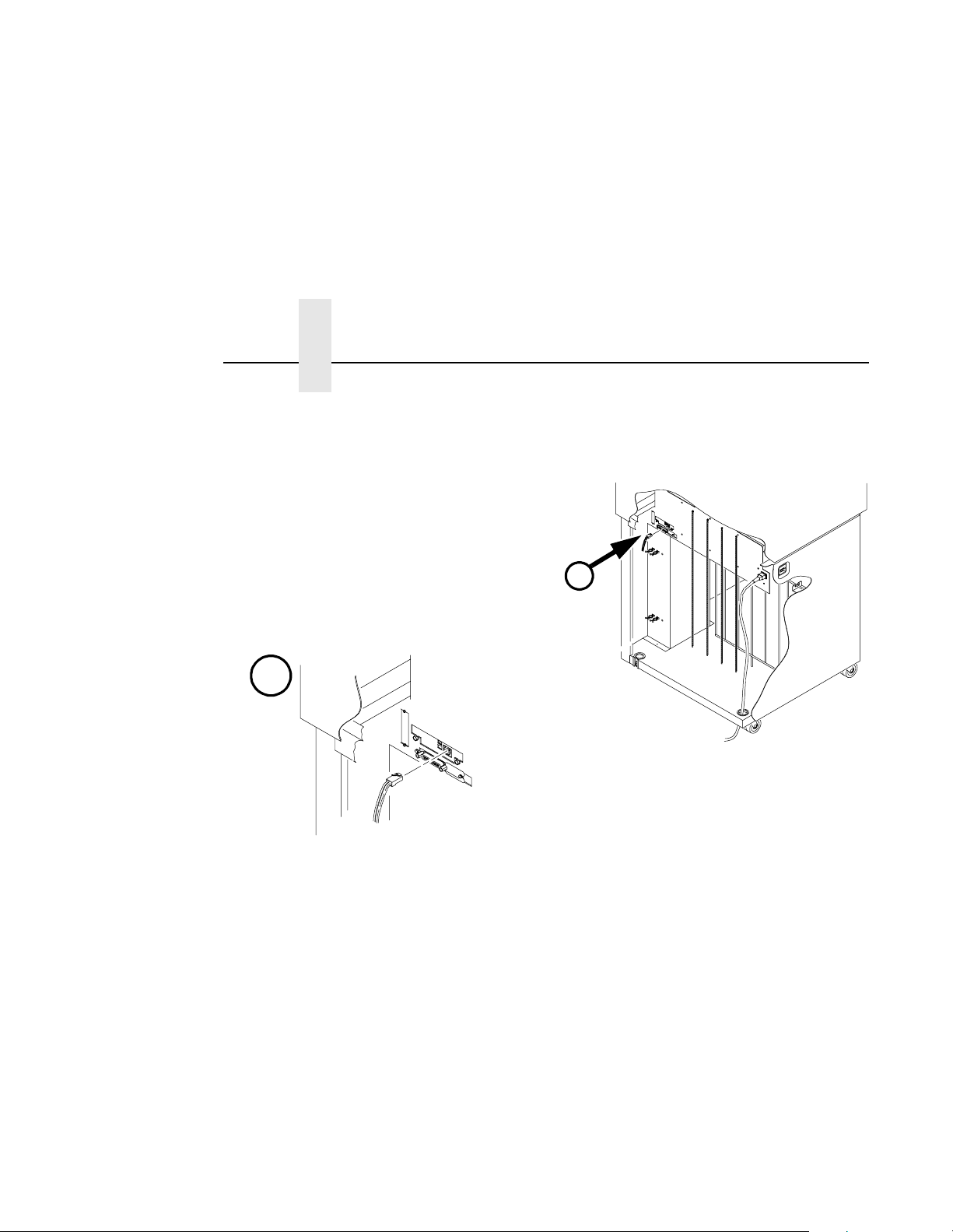
Connecting to the Ne twork
To attach the Ethernet Interface to a network as illustrated in Figure 2,
plug the network cable into the Ethernet Interface connector.
Watch the LEDs in the rear of the printer as they cycle through the power
on self-test (see page 15). When the test is complete, the STAT led is
flashing.
19
Page 20
Chapter 2 Installation
$
$
20
Network Connector
Figure 2. Physical Setup
Page 21

Configuration Tools
There are two parts to an Ethernet Interface setup:
1. Configuring the Ethernet Interface so it can be seen on the network.
This involves network related settings (e.g. an IP address within TCP/
IP environments) configured through the built-in command shell,
npsh, printer web page or from the operator panel.
2. Configuring a host with a new printer so it knows how to send data to
the Ethernet Interface. Just being able to see the printer on the
network does not mean you can automatically print to it. A host has to
be told where to send the data.
NOTE: Some network environments do not require any network settings
to be configured on the Ethernet Interface. However, all network
setups require configuration on the host end.
Configuration using the Printer Operator Panel
The Ethernet Interface settings can be set from the printer operator panel.
The procedure is described below.
Configuration using the Printer Operator Panel
IMPORTANT
When the printer is first powered on, the message "ETHERNET
ADAPTER IS BEING INITIALIZED" displays on the operator panel.
This process takes about two minutes. Make sure not to change the
Ethernet Interface settings while this message is displayed to
prevent a loss of Ethernet Interface configuration information. When
the initialization is complete, the message "ETHERNET ADAPTER IS
READY" displays, and the Ethernet Interface settings may be safely
changed from the operator panel.
You can set any of three listed parameters from the operator panel.
These parameters are located in the “Ethernet Parameters” menu. The
available parameters are:
• IP Addres s
• Gateway Address
• Subnet Mask
21
Page 22

Chapter 2 Configuration Tools
The procedure for changing any of the parameters is the same. The
procedure for changing the IP Address is given here as an example. Use
the same procedure for the other required parameters. To change the IP
Address parameter:
1. Power on the printer.
2. Press STOP to get to NOT READY state.
3. Press Menu to display OPERATOR MENU.
4. Press Scroll until ETHERNET PARAMETERS is displayed, t hen press Enter.
5. Press Enter again then Scroll to choose an IP address octet to change, then press Enter.
6. Press Scroll to choose the desired value for the octet, then press
Enter. The new value is shown with an asterisk. Press Return.
7. Repeat steps 5 through 6 until all IP address octets are set to the desired value.
8. Press Return until ETHERNET PARAMETERS is on the first display line.
IMPORTANT
22
9. Press Scroll to choose other IP parameters to change, then follow
the above steps for these as well.
10. When finished, press Return multiple times until NOT READY is displayed.
11. Press Start.
12. Wait for “ETHERNET ADAPTER IS READY” message to display.
When a change is made from the operator panel, the Ethernet
Interface is re-initialized. The messages "ETHERNET ADAPTER IS
BEING RESET" and "ETHERNET ADAPTER IS BEING INITIALIZED"
display on the operator panel. This process takes several minutes.
Make sure not to shut the printer off or make further changes to the
Ethernet Interface settings during this initialization period to prevent
a loss of Ethernet Interface configuration information. When the
initialization is complete, the message "ETHERNET ADAPTER IS
READY" is displayed.
Page 23

HTML Forms
Test the setting by performing a
prompt as follows:
ping
ip_address
where the
Interface. If this does not work, repeat the steps to make sure the IP
values on the operator panel are correct. If they are correct, contact your
network administrator for possible network problems.
NOTE: Unlike most operator panel settings, the Ethernet Interface
ip_address
settings are not saved in Custom Sets; instead, they are stored
directly on the Ethernet Interface adapter.
ping
command from an OS/2* command
is the IP address of the printer Ethernet
HTML Forms
The Ethernet Interface settings can be configured over TCP/IP through a
standard Web browser. The Ethernet Interface Web pages provide a
handy way to access some of the commands built in to the print server.
NOTE: If a router is used, make sure a gateway value is configured.
To access the Ethernet Interface home page:
1. Make sure the print server has an IP address and subnet mask so it is
recognizable on your TCP/IP network.
2. Make sure your network station can successfully “
Interface over the network.
3. Direct your Web browser to the Uniform Resource Locator (URL)
http://
“
IPaddress
”
(e.g. “http://192.75.11.9”).
ping” the Ethernet
23
Page 24
Chapter 2 Configuration Tools
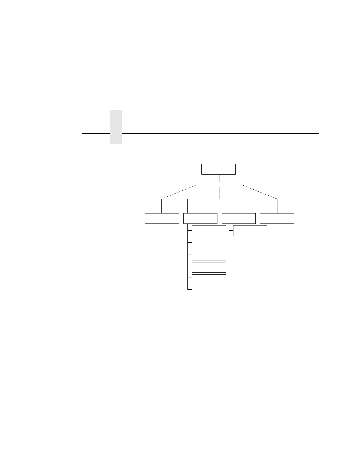
The Ethernet Interface HTML structure is divided into several menus as
shown in Figure 3.
Index/Home
Home Page Menu
About
Configuration
Network
Print Path
I/O Port
HTTP
Administration
System
Status Help
I/O Port
Figure 3. Ethernet Interface HTML Structure
NOTE: Online help is available for all HTML pages.
24
Page 25
HTML Forms
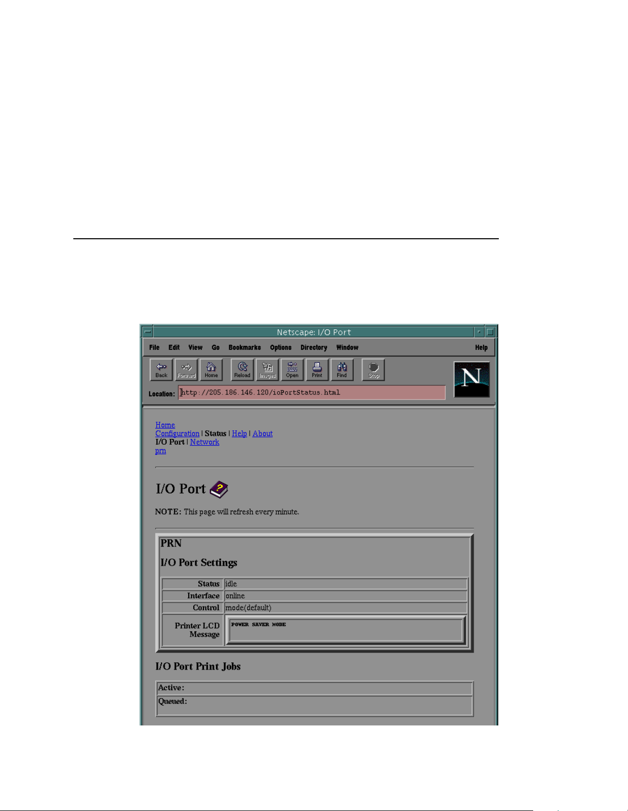
Printer Status Screen
Using the printer IP Address and any standard web browser, you can
check the status of the printer. Figure 4 shows the exact state of the
printer by showing the printer LCD message.
Figure 4. WWW Printer Status Screen
25
Page 26

Chapter 2 Configuration Tools
Configurat ion A l ter nat ives
Besides the HTML forms and software provided, the Ethernet Interface
internal command shell, npsh, can also be reached using these methods:
Telnet
A TCP/IP command that helps configure Ethernet Interface settings
remotely. A TCP/IP host starts a Telnet session with the print server and
logs in to the device command shell to alter and view settings.
Example:
telnet 192.75.11.9
Remote Shell
A TCP/IP command that helps configure print server settings remotely. A
TCP/IP host uses this command to remotely execute a single command
on the Ethernet Interface.
Example:
rsh spike list prn
This command remotely executes the npsh command “list prn” on
the Ethernet Interface named
spike
.
26
Page 27

3 OS/2 Configuration
Overview
This chapter details a complete OS/2 configuration setup including:
1. Configuring the Ethernet Interface with its TCP/IP settings
2. Configuring a new printer on an OS/2 workstation. The procedure
given will be from an OS/2 Warp 4 system, but the setup is similar to
OS/2 Warp 3 and v2.11.
OS/2 must have TCP/IP installed on it and be configured with the correct
IP parameters. See OS/2 documentation/help and your network
administrator.
Configuring the Ethernet Interface TCP/IP Setting s
There are mandatory TCP/IP settings (i.e., an IP address and subnet
mask) needed before the print server can be detected on the network.
There are also some additional settings that you may want to configure
but these are optional. This section offers alternative methods for
configuring your Ethernet Interface within an OS/2 environment and
mentions some of the more common optional settings available.
27
Page 28

Chapter 3 OS/2 Workstation Configuration
Mandatory Settings
The Ethernet Interface must be configured with an IP address and subnet
mask at a minimum. Consult your network administrator to obtain the
proper values for these parameters. To configure the IP address and
subnet mask, see “Configuration Tools” on page 21.
Optional Settings
One additional setting, the gateway address, is necessary if the OS/2
workstations must communicate with the Ethernet Interface across a
router. Consult your network administrator to obtain the proper value for
this parameter. To configure the gateway address, see “Configuration
Tools” on page 21.
OS/2 Workstation Configuration
OS/2 must use the TCP/IP LPR protocol in order to send jobs to the
Ethernet Interface to be printed. This section will explain how to use the
LPR command and how to setup an OS/2 print queue which will forward
jobs to the printer using the LPR protocol.
28
Using the LPR Command
At an OS/2 command prompt, enter lpr -s
EthernetInterface_queue filename
NOTE: This name must be the name of an existing destination/queue on
the Ethernet Interface and it must be lowercase by default. You
will most likely use d1prn.
Troubleshooting
Check the IP information on both the Ethernet Interface and the OS/2
station for correctness. Make sure the
actually defined on the Ethernet Interface and that you are spelling it
correctly.
EthernetInterface_queue
ip_address
-p
is
Page 29

Using an OS/2 LPR Print Queue
NOTE: During Power Up, the printer performs an interface hardware test.
The presence of the Ethernet Interface menu selections at the
printer operator panel indicates that the Ethernet Interface
hardware is functioning properly. See the
configuration menu information.
Setup Guide
for
Using a n O S /2 LP R P rin t Que u e
This section describes how to setup an OS/2 Warp 4 print queue to print
to the Ethernet Interface using the LPR protocol. TCP/IP for OS/2 must
be installed on your OS/2 workstation. This procedure is similar to OS/2
Warp 3 and v2.11.
To setup the printer queue:
1. Find the Printer template icon. It may be in the Printers folder or the Templates folder.
2. Right click on the icon then select “Install.” The “Create a printer”
dialog box is displayed.
3. Enter any desired name for the printer. This will be the name of the printer queue.
4. In the “Default printer driver” list, select the desired driver. If the
desired driver does not appear in the list, click on “Install new printer
driver...” and follow the instructions to install the desired driver.
5. In the “Output port” list, double click on an unshaded \PIPE\LPDx
port. If all are shaded, you will have to double click on a shaded port
and change the parameters. If no \PIPE\LPDx ports are shown, follow
these steps to install them:
a. Right click on a port and select “Install.”
b. Select the “New port drivers” radio button.
d
c. In the “Directory” field, type
where the TCPIP subdirectory exists.
d. Click on “Refresh.” Several \PIPE\LPDx port icons should appear
in the “Output port” list. If none appear, type
step c. and try this step again.
:\TCPIP\DLL
where d: is the drive
d
:\MPTN\DLL
in
29
Page 30

Chapter 3 OS/2 Workstation Configuration
NOTE: If no ports appear after completing step d., search your drives for
the LPRPDRVR.PDR and type the path to this file, not including
the file name, in step c. The final step available is to ask OS/2
support to install these ports.
e. Select all the ports with the mouse pointer and click on “Install.”
The \PIPE\LPDx ports should now show in the “Output port” list.
6. The “\PIPE\LPDx - Setting” dialog box is displayed.
7. In the “LPD server” field, type the IP address of the Ethernet Interface.
8. In the “LPD printer” field, type the name of the defined destination /
queue on the Ethernet Interface.
NOTE: This name must be the name of an existing destination/queue on
the Ethernet Interface and it must be lowercase by default. You
will most likely use ‘d1prn’. If the IPDS* feature is installed,
queue name ‘d4prn’ is not available.
9. Optionally, click on “Help” to understand the other parameters and
enter those values.
30
10. Click “OK.”
11. Click on “Create.” The print queue is created and placed in the
Printers folder or possibly on the OS/2 desktop.
12. Make sure LPRPORTD is running. Type
for a line that contains LPRPORTD. If it is running, this process is
complete. If it is not running, enter the following at the OS/2 command
prompt:
Ctrl-Esc
and check the list
start lprportd
You will likely want to put this command in your “STARTUP.CMD” file,
or use the TCP/IP Configuration tool to set it to autostart on boot up.
Any jobs sent to this queue will now be forwarded to the Ethernet
Interface to be printed.
Page 31

Using an OS/2 LPR Print Queue
Starting the LPR Port Daemon
The LPR Port Daemon must be started to enable TCP/IP printing. To start
the LPR Port Daemon;
1. Open the TCP/IP folder, which is in the OS/2 System folder for Warp
3.0.
2. Open TCP/IP Configuration.
3. Select the “Autostart” tab on the notebook.
4. In “Services to Autostart,” select “lprportd.”
5. Select “Foreground Session” and “Minimized.”
6. Close the notebook by double clicking the system icon, which is located in the upper left corner.
7. Select “Save.”
Yes
8. If prompted, respond
to save the configuration changes.
9. At the OS/2 command prompt, enter
tcpstart
to restart TCP.
T rou bleshooting
NOTE: During Power Up, the printer performs an interface hardware test.
The presence of the Ethernet Interface menu selections at the
printer operator panel indicates that the Ethernet Interface
hardware is functioning properly. See the
configuration menu information.
Check the IP information on both the Ethernet Interface and OS/2 station
for correctness.
Make sure the value in step 8 is actually defined on the Ethernet
Interface. See “Configuration Tools” on page 21 to determine how to
verify this. Verify also that you are spelling the printer name correctly.
Verify that LPRPORTD is running.
Setup Guide
for
31
Page 32

Chapter 3 OS/2 Workstation Configuration
TCP/IP Access Problem
If you can “
browse, Telnet, or print to the printer through the Ethernet Interface, there
may be an incorrect entry in the TCP access list. In order for this
workstation to use the Ethernet Interface in this case, one of two things
must happen.
1. The TCP list must have an entry added to grant access to this workstation.
2. All entries must be deleted from the TCP list to grant all workstations/
hosts access to the above TCP services.
To view the current access list:
Use the printer operator panel to access the configuration menu (see the
Setup Guide
DIAGNOSTICS/Printer Tests menu choose the E-net Test Page. When
the page prints, look under the “TCP ACCESS TABLE” section for the
TCP access list entries.
To add/delete a TCP access list entry, refer to “TCP Access Lists” on
page 179.
NOTE: When the following procedure is used, the TCP access list will be
ping
” the printer from a workstation, but you cannot Web
for configuration menu information). From the
cleared but all IP addresses will need to be entered again after
the procedure is complete.
32
To reset all TCP/IP values to the factory defaults when access is
impossible:
1. Obtain a printer configuration printout using the operator panel. See
Setup Guide
the
2. Power off the printer.
3. On the Ethernet Interface, place SWITCH 2, the center switch, in the down position.
4. Power on the printer and wait for the READY state.
5. On the Ethernet Interface, place SWITCH 2, the center switch, in the up position.
for configuration menu information.
Page 33

Web Browser/HTTP Problem
6. From a workstation attached to this network segment, create an ARP
entry. The Ethernet Interface IP address and hardware or MAC
address are needed. At the workstation enter:
arp -s <
ping <
7. Try to “ping” this IP address to see if the Ethernet Interface can be
8. Telnet into the Ethernet Interface using the same IP address as
9. At the system prompt, enter:
ipaddress
ipaddress
seen on your network. If the interface does not respond, verify you
are on the same network segment as the printer and that the ARP
entry was created.
above. Log in as root with no password.
> <
>
MACaddress
>
store tcpip from default
config http on
reset
NOTE: This will reset all TCP/IP settings to factory default and reset the
Ethernet Interface.
10. Wait five minutes for the Ethernet Interface to reset.
11. Power the printer off and then back on.
12. Wait for the “ETHERNET ADAPTER IS READY” message to display.
13. Set the IP address, subnet mask, and default gateway parameters to
the desired values. (see “Configuration Tools” on page 21).
Web Browser/HTTP Problem
In some cases you may not be able to browse the printer web page
simply because the Ethernet Interface HTTP may be turned off.
ping
If you cannot “
Address, subnet mask, and default gateway are set correctly by checking
the Ethernet Parameters menu from the operator panel. See the
for configuration menu information.
Guide
If you can “
the web pages, perform the following procedure to verify the Ethernet
Interface HTTP is turned on.
ping
” the Ethernet Interface IP address, make sure the IP
Setup
” the Ethernet Interface IP address but can not access
33
Page 34

Chapter 3 OS/2 Workstation Configuration
1. Telnet into the Ethernet Interface and log in as root with no password.
2. At the system prompt enter the following commands:
config http on
save
reset
3. After approximately 5 minutes, point your browser to the Ethernet
Interface IP address. The printer web pages should now be
accessible.
If you are still experiencing difficulty accessing or browsing the printer,
contact technical support for further assistance.
34
Page 35

4 AS/400 Configuration for
Overview
an ASCII Printer
This chapter details a complete AS/400* configuration setup including:
1. Developing Line Descriptions with CRTLINETH
2. Configuring the AS/400 for TCP/IP
3. Configuring the AS/400 for Printing
4. Verifying Printing of AS/400 This document assumes no AS/400 printer configuration has been done.
If any configuration has been done, please follow the procedure to the
point at which continued configuration is required.
Developing Line Descriptions with CRTLINETH
For each LAN adapter on the AS/400, a line description needs to be
created for the Ethernet. This is required for Release V3R2 and V3R7.
If a line description already exists, make sure the SSAP list includes
default options “AA” and “12.” You must also know the LAN speed for the
AS/400 LAN adapter.
NOTE: To change a line description, you need to vary the line off before
making the change. After making the change, you need to vary
the line back on.
To change an existing line description, use the CHGLINETH command.
To create a line description, use CRTLINETH.
35
Page 36

Chapter 4 Overview
NOTE: SSAPS of “AA” and “12” are automatically set as default values in
To create a line description, enter the following command:
CRTLINETH LIND(ETHLAN) RSRCNAME(LIN041)
Your completed screen should look like Figure 5.
the line description when “*CALC” is used in creating new line
descriptions. You do not need to set these value s unles s they
have been changed.
36
Figure 5. Example Ethernet Line Description
Page 37

Configuring with ADDTCPIFC
The following three parameters must be specified:
Line description name (LIND)
This line description name is the user’s name for the AS/400 adapter.
This name must be identical to the name entered when the TCP/IP is
configured on the AS/400, as described in “Configuring AS/400 for an
ASCII Printer”, below.
Resource name (RSRCNAME)
System-assigned name for the interface (for example, LN041).
SSAP
When *CALC is used, the values of “12” and “AA” are entered
automatically as defaults. Verify that those SSAP values have not been
changed.
Configuring AS/400 for ASCII using TCP /IP
The next step in configuring the AS/400 for the IBM 6400 printer is to
configure the interface on the AS/400 for TCP/IP
NOTE: The AS/400 interface is not the IBM NIC. Do not set the AS/400
interface address to the same address as the NIC IP address.
Also do not add the NIC to the AS/400 TCP/IP interface list.
Configuring with ADDTCPIFC
ADDTCPIFC is used to add a TCP/IP interface to AS/400. This step
configures the AS/400 for attachments to a TCP/IP network.
At the AS/400 command line, enter the following command:
ADDTCPIFC INTNETADR (’9.99.15.188’) LIND(ETHLAN)
SUBNETMASK(’255.255.255.0’)
Your completed screen shou ld loo k like F igu re 6.
37
Page 38

Chapter 4 Configuring AS/400 for ASCII using TCP/IP
System: BLDD6
Internet address . . . . . . . . . . . . . . . . . . . . : 9.99.15.188
Subnet mask. . . . . . . . . . . . . . . . . . . . . . . : 255.255.255.0
Line description . . . . . . . . . . . . . . . . . . . . : ETHLAN
Line type. . . . . . . . . . . . . . . . . . . . . . . . . . . : *Elan
Interface status. . . . . . . . . . . . . . . . . . . . . . : Inactive
Type of service. . . . . . . . . . . . . . . . . . . . . . : *Normal
Maximum transmission unit . . . . . . . . . . . . : *Lind
Automatic start . . . . . . . . . . . . . . . . . . . . . . : *Yes
Figure 6. Example ADDTCPIFC Interface
The following parameters must be spe cifie d:
Internet Address
Internet address of the AS/400 Ethernet LAN adapter.
NOTE: Do not use the IP address of the NIC.
38
Subnet Mask
The Subnet Mask for this AS/400 TCP/IP interface (for example,
255.255.255.0).
Line Description
The name assigned to the AS/400 line description as described in
“Developing Line Descriptions with CRTLINETH” on page 35.
NOTE: Each AS/400 LAN adapter will have its own line description.
Configuring a Router Definition with ADDTCPRTE
If necessary, use the ADDTCPRTE command to create a route definition.
This is required if the printer is somewhere other than on a local segment
and must cross bridges.
Page 39

Configuring a Local Domain and Hostname
Configuring a Local Domain and Hostname
The AS/400 print commands, described in “Setting up Printing for ASCII
Files” on page 40, require a local name and hostname. If you have
already configured LAN attached TCP/IP printers on the AS/400 system,
you will have a local domain name and hostname configured on the
system.
NOTE: If you already have a local domain name and hostname
configured on the system, do not change your setup.
If the local domain name and hostname file is empty, the file must be
setup. This control file information is used to determine if a print request
comes from an authorized host.
To configure the local domain and hostname, you will run the CFGTCP
command and select Option “12” from the menu. Enter a local domain
name, such as
as400-01
hostname for your system in the host entry table. Refer to “Configuring a
TCP/IP Host Table Entry”, below.
city.company.com
. This is the name of your AS/400 system and must match the
. Enter a local hostname, such as
NOTE: If the printer and AS/400 are not on the same local LAN segment,
use CFGTCP Option 2 to verify that there is a route defined in the
TCP/IP route list.
Configuring a TCP/IP Host T able Entry
Although it is optional to create a TCP/IP host table entry, IBM suggests
that you take this step. Add the AS/400 name and the IP address of the
LAN adapter to the “Host Table Entries.”
39
Page 40

Chapter 4 Configuring the AS/400 for Printing
Configuring the AS/400 for Printing
The procedure for configuring an AS/400 for printing requires that you:
1. Setup the printing capability
2. Verify the setup with a print job
In order to accomplish this configuration, you need the following
information:
Remote Printer Queue name
Set for any of ‘d1prn’ through ‘d4prn’.
NOTE: The Remote Printer Queue name must be all lower case. Do not
use PASS.
NOTE: When the IPDS feature is installed, queue name ‘d4prn’ is not
available.
IP address
40
IP address for the NIC.
Setting up Printing for ASCII Files
The next stop in configuring the AS/400 for IBM network printers is to
setup the remote printing capability. There are two ways to do this. You
can specify the LPR parameters manually each time you send a file to the
printer, or use Remote Writer and a remote output queue for automatic
printing to the printer.
To use LPR manually:
1. Start TCP/IP, if it is not already running, by entering the command
STRTCP
2. At the AS/400 command line, enter
3. The following example displays only the parameters you need to specify.
.
LPR
.
Page 41

Setting up Printing for ASCII Files
Send TCP/IP Spooled File (LPR)
Type choices, press Enter.
Remote system RMTSYS > *INTNETADR
Printer queue PRTQ > ‘d1prn’
Job name JOB *
User
Number
Spooled file number SPLNMBR *ONLY
Destination type DESTTYP *OTHER
Transform SCS to ASCII TRANSFORM *YES
Manufacturer type and model MFRTYPMDL > *IBM6400EP
Internet address INTNETADR > ‘9.99.2.3’
The following parameter values are required:
Remote system
Enter the hostname of your printer or *INTNETADR, which then prompts
you to specify the IP address of your printer.
Printer Queue (PRTQ)
Set to ‘d1prn’ through ‘d4prn’. The remote printer queue name must be
all lower case, entered in single quotes.
NOTE: When the IPDS feature is installed, queue name ‘d4prn’ is not
available.
Destination type (DESTTYP) Specify *OTHER for the DESTTYP parameter.
Transform (TRANSFORM)
Specify *YES.
41
Page 42

Chapter 4 Configuring the AS/400 for Printing
Manufacturer Type and Model (MFRTYPMDL)
Select a manufacturer type and model. This is the name of the WSCO.
Select *IBM6400EP for Epson** emulation or *IBM6400 or *IBM42023 for
Proprinter* Emulation if you have AS/400 V3R2 and above or V3R7 and
above.
Internet Address (INTNETADR)
IP address of the NIC.
NOTE: You may specify either *INTNETADR (and the NIC IP address) or
the hostname for the NIC (if you added the printer to the host
table entry as directed in “Configuring a TCP/IP Host Table Entry”
on page 39).
42
Page 43

Setting up Printing for ASCII Files
To create an Automatic Remote Output Queue:
1. From the AS/400 command line, enter
CRTOUTQ
.
2. The following example displays the parameters you need to specify.
Send TCP/IP Spooled File (LPR)
Type choices, press Enter.
Output queue. . . . . . . . . . . . . . . . . . . . . . . . . . . OUTQ > USERNAME
Library . . . . . . . . . . . . . . . . . . . . . . . . . . . . *CURLIB
Maximum spooled file size:. . . . . . . . . . . . . . . . . MAXPAGES
Number of pages . . . . . . . . . . . . . . . . . . . . *NONE
Staring time . . . . . . . . . . . . . . . . . . . . . . . .
Ending time . . . . . . . . . . . . . . . . . . . . . . . .
+ for more values
Order of files on queue . . . . . . . . . . . . . . . . . . . . SEQ *FIFO
Remote system . . . . . . . . . . . . . . . . . . . . . . . . . RMTSYS > *INTNETADR
Remote printer queue. . . . . . . . . . . . . . . . . . . . RMTPRTQ > ‘d1prn’
Writers to autostart. . . . . . . . . . . . . . . . . . . . . . AUTOSTRWTR 1
Queue for writer messages. . . . . . . . . . . . . . . . . MSGQ QSYSOPR
Library . . . . . . . . . . . . . . . . . . . . . . . . . . . . *LIBL
Connection type . . . . . . . . . . . . . . . . . . . . . . . . CNNTYPE > *IP
Destination type . . . . . . . . . . . . . . . . . . . . . . . . DESTTYP XAUTOQ XAIX
Host print transform . . . . . . . . . . . . . . . . . . . . . TRANSFORM *YES
Manufacturer type and model . . . . . . . . . . . . . MFRTYPMDL > *IBM6400EP
Workstation Customizing Object. . . . . . . . . . . . . WSCST *NONE
Library . . . . . . . . . . . . . . . . . . . . . . . . . . . .
Internet address . . . . . . . . . . . . . . . . . . . . . . . . INTNETADR > ‘9.99.57.173’
Destination options . . . . . . . . . . . . . . . . . . . . . . . DESTOPT *NONE
Print separator page . . . . . . . . . . . . . . . . . . . . . . SEPPAGE *YES
User defined option. . . . . . . . . . . . . . . . . . . . . . . USRDFNOPT *NONE
43
Page 44

Chapter 4 Configuring the AS/400 for Printing
3. Enter values for the following parameters:
Output queue (OUTQ)
The name of the AS/400 output queue. The name can be anything you
would like. This name is not the same as the printer internal queue name,
‘d1prn’.
NOTE: When the IPDS feature is installed, queue name ‘d4prn’ is not
available.
Remote system (RMTSYS)
Internet address of the NIC on the printer (*INTNETADR prompts you for
this) of the hostname of the NIC.
Remote printer queue (RMTPRTQ) Default name of the IBM network printer. Set for any of ‘d1prn’ through
‘d4prn’. The remote printer queue name must be all lower case, entered
in single quotes.
44
NOTE: When the IPDS feature is installed, queue name ‘d4prn’ is not
available.
Writer to Autostart (AUTOSRTWTR)
Set the value to 1. This will start the Remote Writer when the queue is
created, and it is automatically starts the Remote Writer after each IPL of
the AS/400 and whenever STRTCP is started.
Connection type (CNNTYPE) Specify this value as *IP.
Destination type (DESTTYP)
Specify XAUTOQ XAIX. XAUTOQ is a performance enhancement, in
which data is not required to be transformed again if the connection is
interrupted. XAIX allows printing of multiple copies.
Tr an sf or m (T R ANSF ORM) Specify this value as *YES.
Page 45

Manufacturer type (MFRTYPMDL)
Select a manufacturer type and model. This is the name of the WSCO.
Select *IBM6400EP for Epson emulation or *IBM6400PR or *IBM42023
for Proprinter Emulation.
Internet address (INTNETADR)
Specify the IP address of the printer.
V erify Printing on AS/400
This section verifies that the printer is capable of printing ASCII files and
that the printer can be pinged on the network.
To test ASCII printing:
1. Start TCP/IP, if it is not already running, by entering the command
STRTCP
2. Verify that the AS/400 TCP/IP interface is active.
3. Ping the printer from an AS/400 workstation with the command:
ping
.
ip_address
Setting up Printing for ASCII Files
.
Where
printer (the NIC) or the hostname of the printer (if you put the
hostname in the host entry table as directed in “Configuring a TCP/IP
Host Table Entry” on page 39).
4. If the printer cannot be pinged, proceed to “AS/400 ASCII
Troubleshooting” on page 46.
5. Use one of the following methods to send a spooled file to the printer:
ip_address
is the Internet address of the remote system
• Enter the LPR command on the AS/400 command line with the
appropriate parameters. See “To use LPR manually:” on page 40.
• Enter
name
internet queue, as described in “To create an Automatic Remote
Output Queue:” on page 43).
• Use the
STRRMTWTR
is the name of the AS/400 remote output queue (not the printer
WRKOUTQ
name
on the AS/400 command line, where
command to send jobs.
45
Page 46

Chapter 4 AS/400 ASCII Troubleshooting
AS/400 ASCII T r oubleshooting
During Power Up, the printer performs an interface hardware test. The
presence of the Ethernet Interface menu selections at the printer operator
panel indicates that the Ethernet Interface hardware is functioning
properly. See the
If you have trouble pinging the printer:
1. Verify the configuration of AS/400, including the printer and any
intervening devices such as routers and bridges.
2. Verify that the AS/400 line description is varied on and the printer is
turned on and displays a status of READY.
3. Verify that the AS/400 TCP/IP is active.
TCP/IP Access Problem
Setup Guide
for configuration menu information.
46
If you can “
browse, Telnet, or print to the printer through the Ethernet Interface, there
may be an incorrect entry in the TCP access list. In order for this
workstation to use the Ethernet interface in this case, one of two things
must happen.
1. The TCP list must have an entry added to grant access to this workstation.
2. All entries must be deleted from the TCP list to grant all workstations/
hosts access to the above TCP services.
To view the current access list:
Use the printer operator panel to access the menu. See the
for configuration menu information. From the Operator Print Test menu
choose the Ethernet Test Page. When the page prints, look under the
“TCP ACCESS TABLE” section for the TCP access list entries.
To add/delete a TCP access list entry, refer to “TCP Access Lists” on
page 179.
NOTE: When the following procedure is used, the TCP access list will be
ping
” the printer from a workstation, but you cannot Web
Setup Guide
cleared but all IP addresses will need to be entered again after
the procedure is complete.
Page 47

TCP/IP Access Problem
To reset all TCP/IP values to the factory defaults when access is
impossible:
1. Obtain a printer configuration printout using the operator panel. See
Setup Guide
the
2. Power off the printer.
3. On the Ethernet Interface, place SWITCH 2, the center switch, in the down position.
4. Power on the printer and wait for the READY state.
5. On the Ethernet Interface, place SWITCH 2, the center switch, in the up position.
6. From a workstation attached to this network segment, create an ARP
entry. The Ethernet IP address and hardware or MAC address are
needed. At the workstation enter:
arp -s <
ping <
ipaddress
for configuration menu information.
ipaddress
> <
MACaddress
>
>
7. Try to “
seen on your network. If the interface does not respond, verify you
are on the same network segment as the printer and that the ARP
entry was created.
8. Telnet into the printer Ethernet Interface using the same IP address
as above. Log in as root with no password.
9. At system prompt, enter:
ping
” this IP address to see if the Ethernet Interface can be
store tcpip from default
config http on
reset
NOTE: This will reset all TCP/IP settings to factory default and reset the
Ethernet Interface.
10. Wait five minutes for the Ethernet Interface to reset.
11. Power the printer off and then back on.
12. Wait for the “ETHERNET ADAPTER IS READY” message to display.
13. Set the IP address, subnet mask, and default gateway parameters to
the desired values. (See “Configuration Tools” on page 21.)
47
Page 48

Chapter 4 AS/400 ASCII Troubleshooting
Web Browser/HTTP Problem
In some cases you may not be able to browse the printer web page
simply because the Ethernet Interface HTTP may be turned off.
ping
If you cannot “
Address, subnet mask, and default gateway are set correctly by checking
the Ethernet Parameters menu from the operator panel. See the
for configuration menu information.
Guide
If you can “
the web pages, perform the following procedure to verify the Ethernet
Interface HTTP is turned on.
1. Telnet into the Ethernet Interface and log in as root with no password.
2. At the system prompt enter the following commands:
ping
config http on
save
reset
3. After approximately 5 minutes, point your browser to the Ethernet
Interface IP address. The printer web pages should now be
accessible.
” the Ethernet Interface IP address, make sure the IP
” the Ethernet Interface IP address but can not access
Setup
48
If you are still experiencing difficulty accessing or browsing the printer,
contact technical support for further assistance.
Page 49

5 AS/400 Configuration for
an IPDS Printer
Configuring on AS/400 as an IPDS Printer
Use this chapter to configure your IBM 6400 printer on AS/400 as an
IDPS printer. To print IPDS, you must install the IPDS option on your
printer. Once configured as an IPDS printer, the printer can also print
AFP* and SCS, but these datastreams must be converted to IPDS first.
See “Printing AFP, IPDS, and SCS Files”, below.
Printing AFP, IPDS, and SCS Files
IBM 6400 network printers configured as IPDS only print IPDS files. AFP
and SCS files can be printed, but they must be transformed to IPDS
before printing.
• APF files are transformed directly by Print Services Facility*
(PSF/400, an integrated feature of OS/400), which then sends the
transformed file to the printer.
• SCS files are transformed into IPDS by setting the IPDSPASTHR
parameter to YES (see Figure 9 on page 58 or Figure 10 on page 61).
This path yields the best performance by sending IPDS files directly
to the printer with no transform.
49
Page 50

Chapter 5 Configuring on AS/400 as an IPDS Printer
Requirements
Contact IBM to obtain the latest PTFs for PSF/400.
For IPDS printing, you also need to install the IPDS option for the printer.
Configuration Checklist
NOTE: All of the following configuration steps carried out on the AS/400
may require “create” or “change” authority.
1. If you have not already done so, set up the printer and install the NIC. See Chapter 2.
2. Using the printer operator panel, set up the printer for IPDS by setting
the parameters and values shown in Table 3.
Table 3. Operator Panel Settings
Menu Item Setting
PRINTER CONTROL Interface Selection
• AUTO SWITCH if you use the
printer for other than IPDS
printing
• ETHERNET for IPDS only
IPDS IPDS Emulation Mode 4234-12
3. Set TCP/IP addresses for the printer, such as an IP Address,
Gateway Address, or Subnet Mask. See “Configuration Tools” on
page 21.
4. If the printer and AS/400 are not on the same LAN segment, verify
there is a route defined in the TCP/IP route list. If necessary, use the
ADDTCPRTE command to create a route definition. You need this if
your printer is somewhere other than on a local segment.
5. You need the IP address of the NIC to configure the NIC.
6. If you have not yet done so, create a line description for your Ethernet
IBM NIC. See “Developing Line Descriptions with CRTLINETH” on
page 35.
50
Page 51

Configuration Checklist
7. Create or verify the existence of an AS/400 TCP/IP interface for
Ethernet. See “Configuring an AS/400 TCP/IP Interface with
ADDTCPIFC” on page 52.
8. The next step depends on your AS/400 release. Configure your
printer with one of these procedures:
• “Configuring PSF/400 for IPDS on V3R2” on page 54
• “Configuring PSF/400 for IPDS on V3R7 and Above” on page 60
9. Verify the printer is ON using the VFYCFG command.
10. Verify that TCP/IP has been started using the STRTCP command.
11. Test your configuration. See “Verifying the IPDS Configuration on AS/
400” on page 65.
12. To share the printer on the network, verify that the necessary
parameters have been set correctly. See “Sharing the AS/400 Printer
on the Network” on page 67.
13. If you have problems, refer to “AS/400 Troubleshooting” on page 70.
51
Page 52

Chapter 5 Configuring on AS/400 as an IPDS Printer
Configuring an AS/400 TCP/IP Interface with ADDTCPIFC
NOTE: Do not enter the IP address of the NIC. Do not set the AS/400
interface address to the same address as the NIC IP address.
Also, do not add the NIC to the AS/400 TCP/IP interface list.
Configuring an Interface for Ethernet
ADDTCPIFC is used to add a TCP/IP interface to AS/400. This step
configures the AS/400 for attachments to a TCP/IP network.
At the AS/400 command line, enter the following command:
ADDTCPIFC INTNETADR (’9.99.15.188’) LIND(ETHLAN)
SUBNETMASK(’255.255.255.0’)
Your completed screen should look like Figure 7.
System: BLDD60
Internet address . . . . . . . . . . . . . . . . . . . . : 9.99.15.188
Subnet mask. . . . . . . . . . . . . . . . . . . . . . . : 255.255.255.0
Line description . . . . . . . . . . . . . . . . . . . . : ETHLAN
Line type. . . . . . . . . . . . . . . . . . . . . . . . . . . : *ELAN
Interface status. . . . . . . . . . . . . . . . . . . . . . : Inactive
Type of service. . . . . . . . . . . . . . . . . . . . . . : *NORMAL
Maximum transmission unit . . . . . . . . . . . . : *LIND
Automatic start . . . . . . . . . . . . . . . . . . . . . . : *YES
52
Figure 7. Example ADDTCPIFC Interface
Page 53

Configuring an AS/400 TCP/IP Interface with ADDTCPIFC
The following parameters must be specified:
Internet Address
Internet address of the AS/400 Ethernet LAN adapter.
NOTE: Do not use the IP address of the NIC.
Subnet Mask
The Subnet Mask for this AS/400 TCP/IP interface (for example,
255.255.255.0).
Line Description
The name assigned to the AS/400 line description as described in
“Developing Line Descriptions with CRTLINETH” on page 35. Each AS/
400 LAN adapter will have its own line description.
Configuring a TCP/IP Host Table Entry
Although optional, IBM recommends you create a TCP/IP host table
entry. Add the AS/400 name and the IP address of the LAN adapter to the
“Host Table Entries”. Also, add the hostname and IP address of the
printer to the list. You can access the host table entries function by using
the CFGTCP command, then selecting option 10 from the menu.
You can also add entries to your host table for both the hostname and the
fully qualified network name for your system. The entry should match
what you configured for host and domain name. For example, if your
hostname is “RCHASM03” and your domain name is
“RCHLAND.IBM.COM”, your fully qualified network name is
“RCHASM03.RCHLAND.IBM.COM”. In your host entry table, enter both
RCHASM03 and RCHASM03.RCHLAND.IBM.COM.
53
Page 54

Chapter 5 Configuring on AS/400 as an IPDS Printer
Configuring PSF/400 for IPDS on V3R2
To configure IPDS on AS/400 V3R2, use the following commands:
• CRTDEVPRT
• CRTPSFCFG
Configuring PSF with CRTDEVPRT on V3R2
This section describes how to create a printer device description.
1. At the AS/400 command line, enter a command in the form:
CRTDEVPRT DEVD(P6400) DEVCLS(*RMT) TYPE(*IPDS)
MODEL(0) AFP(*YES) AFPATTACH(*APPC) FONT(11)
RMTLOCNAME(TCPIP) FORMFEED(*CONT) TEXT(‘IBM
6400 NETWORK PRINTER’)
2. A completed screen looks like the example shown in Figure 8.
54
Page 55

Configuring PSF/400 for IPDS on V3R2
Display Device Description
Device Description . . . . . . . . . . . . . . . . . . . . . . .: DEVD P6400
Option . . . . . . . . . . . . . . . . . . . . . . . . . . . . . . . . . .: OPTION *ALL
Category of device . . . . . . . . . . . . . . . . . . . . . . . .: *PRT
Automatically created . . . . . . . . . . . . . . . . . . . . . .: NO
Device class. . . . . . . . . . . . . . . . . . . . . . . . . . . . .: DEVCLS *RMT
Device type . . . . . . . . . . . . . . . . . . . . . . . . . . . . .: TYPE *IPDS
Device model. . . . . . . . . . . . . . . . . . . . . . . . . . . .: MODEL 0
Advanced function printing . . . . . . . . . . . . . . . .: AFP *YES
AFP attachment. . . . . . . . . . . . . . . . . . . . . . . . . .: AFPATTACH *APPC
Online at IPL . . . . . . . . . . . . . . . . . . . . . . . . . . . . .: ONLINE *YES
Font . . . . . . . . . . . . . . . . . . . . . . . . . . . . . . . . . . .: FONT
Identifier. . . . . . . . . . . . . . . . . . . . . . . . . . . .: 011
Point size . . . . . . . . . . . . . . . . . . . . . . . . . . .: *NONE
Form feed. . . . . . . . . . . . . . . . . . . . . . . . . . . . . . .: FORMFEED *CONT
Separator drawer . . . . . . . . . . . . . . . . . . . . . . . . .: SEPDRAWER *FILE
Separator program . . . . . . . . . . . . . . . . . . . . . . . .: SEPPGM *NONE
Library. . . . . . . . . . . . . . . . . . . . . . . . . . . . . .:
Printer error message . . . . . . . . . . . . . . . . . . . . . .: PRTERRMSG *INQ
Message queue. . . . . . . . . . . . . . . . . . . . . . . . . . .: MSGQ QSYSOPR
Library. . . . . . . . . . . . . . . . . . . . . . . . . . . . . .: *LIBL
Maximum pending requests . . . . . . . . . . . . . . . . .: MAXPNDRQS 6
Print while converting . . . . . . . . . . . . . . . . . . . . . .: PRTCVT *YES
Print request timer. . . . . . . . . . . . . . . . . . . . . . . . .: PRTRQSTMR *NOMAX
Form definition . . . . . . . . . . . . . . . . . . . . . . . . . . .: FORMDF F1C10110
Library. . . . . . . . . . . . . . . . . . . . . . . . . . . . . .: *LIBL
Character identifier . . . . . . . . . . . . . . . . . . . . . . . .: CHRID *SYSVAL
Remote location . . . . . . . . . . . . . . . . . . . . . . . . .: RMTLOCNAME TCPIP
Local location . . . . . . . . . . . . . . . . . . . . . . . . . . . .: LCLLOCNAME *NETATR
Remote network identifier . . . . . . . . . . . . . . . . . . .: RMTNETID *NETATR
Mode. . . . . . . . . . . . . . . . . . . . . . . . . . . . . . . . . . .: MODE QSPWTR
Dependent location name. . . . . . . . . . . . . . . . . . .: DEPLOCNAME *NONE
Text . . . . . . . . . . . . . . . . . . . . . . . . . . . . . . . . . . . .: TEXT ‘IBM 6400 Network Printer’
Figure 8. Example CRTDEVPRT Command (V3R2)
55
Page 56

Chapter 5 Configuring on AS/400 as an IPDS Printer
3. Values must be entered for the following parameters:
Device Description (DEVD)
The device description or name. This value must match the value entered
for the PSFCFG parameter in “Configuring AFP with CRTPSFCFG on
V3R2” on page 57.
Device Class (DEVCLS) Specify *RMT.
Device Type (TYPE) Specify *IPDS.
Device Model (MODEL) Specify 0.
Advanced Function Printing (AFP)
56
Specify *YES.
AFP Attachment (AFPATT ACH) Specify *APPC. CRTPSFCFG overrides this value.
Font (FONT)
Enter an appropriate value.
Form Feed (FORMFEED) Specify *CONT.
Remote Location (RMTLOCNAME)
Enter the remote location name.
Page 57

Configuring PSF/400 for IPDS on V3R2
Configuring AFP with CRTPSF CFG on V3R2
In V3R1, WRKAFP2 was used to specify RMTLOCNAME, PORT, and
ACTTMR, along with other parameters for PSF. In V3R2, CRTPSFCFG
(Create PSF Configuration Object), which replaced WRKAFP2, was used
to specify these same parameters, along with other parameters.
The PSF configuration object created with this command is used by PSF/
400 when printing IPDS files. The object is used by AS/400 V3R2 only if
the object is in the QGPL library and has the same name as the printer
device description. This information overrides the APPC configuration
information specified in the printer device description.
To configure AS/400 for IPDS printing on V3R2:
1. At the AS/400 command line, enter a command in the form:
CRTPSFCFG PSFCFG(P6400) IPDSPASTHR(*YES)
RLSTMR(*SEC15) TEXT(‘IBM 6400 NETWORK
PRINTER’) RMTLOCNAME(‘128.99.12.134’)
PORT(5001)
2. A completed screen looks like Figure 9.
57
Page 58

Chapter 5 Configuring on AS/400 as an IPDS Printer
PSF configuration: P6400 Library: QGPL
User resource library . . . . . . . . . . . . . . . . . : *JOBLIBL
IPDS pass through. . . . . . . . . . . . . . . . . . : *YES
Activate release timer . . . . . . . . . . . . . . . : *NORDYF
Release timer . . . . . . . . . . . . . . . . . . . . . . : *SEC15
Restart timer. . . . . . . . . . . . . . . . . . . . . . . . : *IMMED
SNA retry count . . . . . . . . . . . . . . . . . . . . . : 2
Delay time between retries. . . . . . . . . . . . . : 0
Blank page . . . . . . . . . . . . . . . . . . . . . . . . . : *YES
Page size control . . . . . . . . . . . . . . . . . . . . : *NO
Resident fonts . . . . . . . . . . . . . . . . . . . . . . : *YES
Resource retention. . . . . . . . . . . . . . . . . . . : *YES
Edge orient. . . . . . . . . . . . . . . . . . . . . . . . . : *NO
Remote location:
Name or address . . . . . . . . . . . . . . . : 128.99.12.134
TCP/IP port . . . . . . . . . . . . . . . . . . . . . . . . : 5001
TCP/IP activation timer . . . . . . . . . . . . . . : 170
PSF defined options:
Text description . . . . . . . . . . . . . . . . . . . . : IBM 6400 Network Printer
Device resource library list: *DFT
58
Figure 9. Example CRTPSFCFG Command (V3R2)
3. The following parameters are required:
PSF configuration (PSFCFG)
The name of the printer device you are config ur in g.
Library Specify QGPL.
IPDS pass through (IPDSPASTHR)
To print SCS files, specify *YES. PSF/400 transforms SCS into IPDS
before printing.
Page 59

Configuring PSF/400 for IPDS on V3R2
Activate release timer (ACTRLSTMR)
Specifies the point at which the release timer (RLSTMR) is activated. Set
to *NORDYF. This means that the release timer is activated when there
are no spooled files in the printer’s output queue with a status of RDY and
the last page of the last spooled file processed has printed. *NORDYF is
used so that all files with a status of RDY are printed before releasing the
session (which does not terminate the writer, however).
Release timer (RLSTMR)
Specifies the amount of time to wait before a session or dialog is released
without terminating the writer. The ACTRLSTMR parameter specifies
when this timer is to be activated. Set the parameter to a value at least
equal to the TIMEOUT value on the printer. IBM recommends *SEC15.
Remote Location name or address (RMTLOCNAME)
Enter the IP address or hostname of the printer.
TCP/IP port (PORT) Specify 5001.
TCP/IP activation time (AC TTMR )
This value specifies the number of seconds that PSF/400 waits for a
printer to respond to an activation request. If only one system is using the
printer, use the default value (170 seconds). If more than one system is
using the printer, specify *NOMAX, which causes PSF/400 to wait
indefinitely for a response to an activation request.
59
Page 60

Chapter 5 Configuring on AS/400 as an IPDS Printer
Configuring PSF/400 for IPDS on V3R7 and Above
To configure IPDS on AS/400 V3R7 and above, use the following
commands:
• CRTPSFCFG (Optional)
• CRTDEVPRT
Configuring AFP with CRT PSFCF G on V3R7 or V4 R1 (Optional)
New for V3R7 is the ability to specify three TCP/IP-related parameters for
PSF in a printer device description: RMTLOCNAME, PORT, and
ACTTMR. In V3R2, CRTPSFCFG (Create PSF Configuration Object),
which replaced WRKAFP2, was used to specify these same parameters,
along with other parameters. In V3R7 and higher, these three parameters
are ignored when specified in a PSF configuration object, since they are
specified in a printer device description. However, you may wish to use a
PSF configuration object to specify other parameters, such as IPDS
passthrough, and so on.
60
The PSF configuration object created with this command is used by PSF/
400 when printing IPDS files only if the object is specified with the
USRDFNOBJ parameter in the printer device description.
To configure AS/400 for IPDS printing on V3R7 or V4R1:
1. At the AS/400 command line, enter a command in the form:
CRTPSFCFG PSFCFG(AFP/6400NETPRT) IPDSPASTHR(*YES)
RLSTMR(*SEC15) TEXT(‘IBM 6400 NETWORK
PRINTER’)
2. A completed screen looks like Figure 10.
Page 61

Configuring PSF/400 for IPDS on V3R7 and Above
PSF Configuration Information
PSF configuration: 6400NETPRT Library: AFP
User resource library . . . . . . . . . . . . . . . . . .: *JOBLIBL
IPDS pass through. . . . . . . . . . . . . . . . . . . .: *YES
Activate release timer . . . . . . . . . . . . . . . . .: *NORDYF
Release timer. . . . . . . . . . . . . . . . . . . . . . . .: *SEC15
Restart timer . . . . . . . . . . . . . . . . . . . . . . . .: *IMMED
SNA retry count . . . . . . . . . . . . . . . . . . . . . .: 2
Delay time between retries . . . . . . . . . . . . .: 0
Blank page. . . . . . . . . . . . . . . . . . . . . . . . . .: *YES
Page size control . . . . . . . . . . . . . . . . . . . . .: *NO
Resident fonts . . . . . . . . . . . . . . . . . . . . . . .: *YES
Resource retention. . . . . . . . . . . . . . . . . . . .: *YES
Edge orient. . . . . . . . . . . . . . . . . . . . . . . . . .: *NO
Remote location:
Name or address . . . . . . . . . . . . . . . .: *NONE
TCP/IP port . . . . . . . . . . . . . . . . . . . . . . . . .: *NONE
TCP/IP activation timer . . . . . . . . . . . . . . .: 170
PSF defined options:
*NONE
Text description . . . . . . . . . . . . . . . . . . . . . .: IBM 6400 Network Printer
Device resource library list: *DFT
Figure 10. Example CRTPSFCFG Command (V3R7 or V4R1)
NOTE: The lines in bold in Figure 10 are not used by PSF/400. Instead,
PSF/400 uses the information entered in the device description
screen.
3. The following parameters are recommended:
PSF configuration (PSFCFG)
The name used for this PSF configuration object. The name must match
the user-defined object name (USRDFNOBJ) in the printer DEVD.
61
Page 62

Chapter 5 Configuring on AS/400 as an IPDS Printer
IPDS pass through (IPDSPASTHR)
To print SCS files, specify *YES, PSF/400 transforms SCS into IPDS
before printing.
Activate release timer (ACTRLSTMR)
Specifies the point at which the release timer (RLSTMR) is activated. Set
to *NORDYF
Release timer (RLSTMR)
Specifies the amount of time to wait before a session or dialog is released
without terminating the writer. The ACTRLSTMR parameter specifies
when this timer is to be activated. Set the parameter to a value at least
equal to the TIMEOUT value on the printer. IBM recommends *SEC15.
.
Configuring PSF with CRTDEVPRT on V3R7 and Above
This section describes how to create a printer device description.
1. At the AS/400 command line, enter a command in the form:
CRTDEVPRT DEVD(P6400) DEVCLS(*LAN) TYPE(*IPDS)
MODEL(0) LANATTACH(*IP) AFP(*YES) PORT(5001)
FONT(11) FORMFEED(*CONT)
RMTLOCNAME(‘128.9.12.134’)
USRDFNOBJ(AFP/6400NETPRT *PSFCFG)
TEXT(‘IBM 6400 NETWORK PRINTER’)
NOTE: Only use the USRDFNOBJ parameter if it was defined in the
previous procedure (see “Configuring AFP with CRTPSFCFG on
V3R7 or V4R1 (Optional)” on page 60).
62
2. A completed screen looks like the example shown in Figure 11.
Page 63

Configuring PSF/400 for IPDS on V3R7 and Above
Display Device Description
5716SS1 V3R7M0 961108 BLDRB1
Device Description . . . . . . . . . . . . . . . . . . . . . . . . . . . : DEVD P6400
Option . . . . . . . . . . . . . . . . . . . . . . . . . . . . . . . . . . . . . . : OPTION *ALL
Category of device . . . . . . . . . . . . . . . . . . . . . . . . . . . . : *PRT
Device class. . . . . . . . . . . . . . . . . . . . . . . . . . . . . . . . . : DEVCLS *LAN
Device type . . . . . . . . . . . . . . . . . . . . . . . . . . . . . . . . . : TYPE *IPDS
Device model . . . . . . . . . . . . . . . . . . . . . . . . . . . . . . . . : MODEL 0
LAN attachment. . . . . . . . . . . . . . . . . . . . . . . . . . . . . . : LANATTACH *IP
User-defined object. . . . . . . . . . . . . . . . . . . . . . . . . . . : USRDFNOBJ 6400NETPRT
Library. . . . . . . . . . . . . . . . . . . . . . . . . . . . . . . . . . : AFP
Object type . . . . . . . . . . . . . . . . . . . . . . . . . . . . . . : *PSFCFG
Data transform program . . . . . . . . . . . . . . . . . . . . . . . . : USRDTATFM *NONE
User-defined driver program . . . . . . . . . . . . . . . . . . . . . : USRDRVPGM *NONE
Advanced function printing . . . . . . . . . . . . . . . . . . . . . . : AFP *YES
Port number. . . . . . . . . . . . . . . . . . . . . . . . . . . . . . . . . : PORT 5001
Online at IPL . . . . . . . . . . . . . . . . . . . . . . . . . . . . . . . . . : ONLINE *YES
Font. . . . . . . . . . . . . . . . . . . . . . . . . . . . . . . . . . . . . . . . : FONT
Identifier . . . . . . . . . . . . . . . . . . . . . . . . . . . . . . . : 011
Point size. . . . . . . . . . . . . . . . . . . . . . . . . . . . . . . : *NONE
Form feed. . . . . . . . . . . . . . . . . . . . . . . . . . . . . . . . . . . : FORMFEED *CONT
Separator drawer. . . . . . . . . . . . . . . . . . . . . . . . . . . . . . : SEPDRAWER *FILE
Separator program . . . . . . . . . . . . . . . . . . . . . . . . . . . . : SEPPGM *NONE
Library. . . . . . . . . . . . . . . . . . . . . . . . . . . . . . . . . . :
Printer error message . . . . . . . . . . . . . . . . . . . . . . . . . . : PRTERRMSG *INQ
Message queue. . . . . . . . . . . . . . . . . . . . . . . . . . . . . . . : MSGQ QSYSOPR
Library. . . . . . . . . . . . . . . . . . . . . . . . . . . . . . . . . . : *LIBL
Activation timer . . . . . . . . . . . . . . . . . . . . . . . . . . . . . . : ACTTMR 170
Maximum pending requests . . . . . . . . . . . . . . . . . . . . . : MAXPNDRQS 6
Print while converting . . . . . . . . . . . . . . . . . . . . . . . . . . : PRTCVT *YES
Print request timer. . . . . . . . . . . . . . . . . . . . . . . . . . . . . : PRTRQSTMR *NOMAX
Form definition. . . . . . . . . . . . . . . . . . . . . . . . . . . . . . . . : FORMDF F1C10110
Library. . . . . . . . . . . . . . . . . . . . . . . . . . . . . . . . . . : *LIBL
Remote location . . . . . . . . . . . . . . . . . . . . . . . . . . . . . : RMTLOCNAME
Name or address . . . . . . . . . . . . . . . . . . . . . . . . . : 128.9.12.134
Dependent location name . . . . . . . . . . . . . . . . . . . . . . . : DEPLOCNAME *NONE
Text . . . . . . . . . . . . . . . . . . . . . . . . . . . . . . . . . . . . . . . . : TEXT IBM 6400 Network Printer
User-defined options . . . . . . . . . . . . . . . . . . . . . . . . . . . : USRDFNOPT
Figure 11. Example CRTDEVPRT Command (V3R7 and above)
63
Page 64

Chapter 5 Configuring on AS/400 as an IPDS Printer
3. Values must be entered for the following parameters:
Device Description (DEVD)
The device description or name.
Device Class (DEVCLS) Specify *LAN.
Device Type (TYPE) Specify *IPDS.
Device Model (MODEL) Specify 0.
LAN attachment (LANATTACH)
Specify *IP.
64
Port number (PORT) Specify 5001.
Font (FONT)
Enter an appropriate value.
Form Feed (FORMFEED) Specify *CONT.
Activation timer (ACTTMR)
This value specifies the number of seconds that PSF/400 waits for a
printer to respond to an activation request. If only one system is using the
printer, use the default value (170 seconds). If more than one system is
using the printer, specify *NOMAX, which causes PSF/400 to wait
indefinitely for a response to an activation request.
Page 65

Configuring PSF/400 for IPDS on V3R7 and Above
Remote Location (RMTLOCNAME)
Enter the IP address or hostname of the printer.
User-Defined Object (USRDFNOBJ)
To use a PSF configuration object, specify its name and library here. This
object type must be *PSFCFG. For V3R7 and higher, a single PSF
configuration object may be referenced by multiple device descriptions, if
required.
V erifying the IPDS Configuratio n on AS/400
To test IPDS printing:
1. If it is not already on, vary on the line description:
VRYCFG CFGTYPE(*LIN)
2. To start TCP/IP, enter
3. Verify that the AS/400 TCP/IP interface is active. Use the command:
STRTCP
.
WRKTCPSTS
and then select option 1.
4. Turn the printer on and wait until the printer operator panel displays
“ETHERNET ADAPTER IS READY”.
ping
5. To verify the printer is connected to AS/400, “
an AS/400 workstation with one of the following commands:
PING ‘
or
PING
Where
printer (the NIC), and
printer, if any.
6. If the “
on page 70.
7. If the “
the command:
VRYCFG (
ip_address
’
hostname
ip_address
ping
” is not successful, refer to “Printer Cannot Be PINGed”
ping
” is successful, vary on the printer device description with
printer_device
is the Internet address of the remote system
hostname
is the hostname you defined for the
) CFGTYPE(*DEV) STATUS(*ON)
” the printer from
65
Page 66

Chapter 5 Verifying the IPDS Configuration on AS/400
8. To use PSF/400 to send an IPDS file to the printer, enter:
STRPRTWTR DEV (
where
printer_device
If you have problems printing, do the following:
printer_device
is the name of the printer.
)
• Print an Ethernet Test Page. Refer to your
Setup Guide
• Verify that port number 5001 is being used.
If you are still unable to print IPDS files, contact IBM Support.
.
66
Page 67

Printer Sharing Parameters
Sharing the AS/4 00 Printer on the Networ k
To support printer sharing, IBM 6400 network printers automatically
switch among all attached ports (serial port, the twinax or coax port, or the
LAN network port). Basically, the printer prints jobs for one port until no
new jobs appear and the port “times out”. The printer then switches to the
next port and does the same thing.
To change the default “time out” value for a port, update the TIMEOUT
value for the port on the appropriate menu (Serial Interface, Ethernet
Parameters, Twinax Interface, or Coax Interface).
Printer Sharing Parameters
To set up AS/400 for printer sharing, set the following parameters.
Table 4. Printer Sharing
AS/400
Version
V3R2 CRTPSFCFG
Where Set Parameter
CHGPSFCFG
Recommended
Value
RLSTMR *NORDYF Specifies the point at which the
release timer (RLSTMR) is
activated. Set to *NORDYF. This
means that the release timer is
activated when there are no
spooled files in the printer’s
output queue with a status of
RDY and the last page of the last
spooled file processed has
printed. *NORDYF is used so
that all files with a status of RDY
are printed before releasing the
session (which does not
terminate the writer).
Description
67
Page 68

Chapter 5 Sharing the AS/400 Printer on the Network
Table 4. Printer Sharing (continued)
AS/400
Version
V3R2 CRTPSFCFG
V3R2 CRTPSFCFG
V3R7
V4R1
Where Set Parameter
CHGPSFCFG
CHGPSFCFG
CRTPSFCFG
CHGPSFCFG
Recommended
Value
ACTRLSTMR *SEC15 Specifies the amount of time to
wait before a session or dialog is
released without terminating the
writer. The ACTRLSTMR
parameter specifies when this
timer is to be activated. Set the
parameter to a value at least
equal to the TIMEOUT value on
the printer. IBM recommends
*SEC15.
ACTTMR *NOMAX The value specifies the number
of seconds that PSF/400 will wait
for a printer to respond to an
activation request. If only one
system will be using the printer,
use the default value (170
seconds). If more than one
system will be using the printer,
set the value to *NOMAX, which
causes PSF/400 to wait
indefinitely for a response to an
activation request.
ACTRLSTMR *NORDYF Specifies the point at which the
release timer (RLSTMR) is
activated. Set to *NORDYF. This
means that the release timer is
activated w hen there are no
spooled files in the printer’s
output queue with a status of
RDY and the l ast page of the l ast
spooled file processed has
printed. *NORDYF is used so
that all files with a status of RDY
are printed before releasing the
session (which does not
terminate the writer).
Description
68
Page 69

Table 4. Printer Sharing (continued)
Printer Sharing Parameters
AS/400
Version
V3R7
V4R1
V3R7
V4R1
Where Set Parameter
CRTPSFCFG
CHGPSFCFG
CRTDEVPRT
CHGDEVPRT
RLSTMR *SEC15 Specifies the amount of time to
ACTTMR *NOMAX The value s pecifies the number
Recommended
Value
Description
wait before a sessi on o r di alog is
released without terminating the
writer. The ACTRLSTMR
parameter specifies when this
timer is to be activated. Set the
parameter to a value at least
equal to the TIMEOUT value on
the printer. IBM recommends
*SEC15.
of seconds that PSF/400 will wait
for a printer to respond to an
activation request. If only one
system will be using the printer,
use the default value (170
seconds). If more than one
system will be using the printer,
set the value to *NOMAX, which
causes PSF/400 to wait
indefinitely for a response to an
activation request.
69
Page 70

Chapter 5 AS/400 Troubleshooting
AS/400 T roubles hooting
Use this section to resolve problems configuring AS/400 on TCP/IP
networks.
Printer Cannot Be PINGed
If you have problems “
ping
”-ing the printer:
• Verify the configuration of AS/400, including the printer and any
intervening devices such as routers and bridges.
• Verify that the AS/400 line description is varied on and the printer is
turned on and displays a status of READY.
• Verify that the AS/400 TCP/IP interface is active.
PSF/400 T erminates When Initialized
If PSF/400 terminates when you initialize it for IPDS printing and issues
message PQT3603, check for the following error codes:
• Code 10 means an incorrect RMTSYS (V3R1 or V3R6) or
RMTLOCNAME (V3R2, V3R7, or V4R1) has been specified for the
printer.
• Code 15 means that PSF/400 timed out waiting for the printer’s
response. You should check the value you entered for Activation
Timer when using WRKAFP2 (V3R1 or V3R6), CRTPSFCFG (V3R2),
or CRTDEVPRT (V3R7 or V4R1).
• Codes 20-39 indicate a general communications failure. Make sure
all of the components in your network are operational, such as
routers. If necessary, call IBM Technical Support.
70
• Codes 40-59 indicate a logic error between PSF and the printer
control unit. Contact IBM support.
Page 71

Spooled Print File Remains in PND Status
Spooled Print File Remains in PND Status
Check the output queue with the command:
WRKOUTQ
This typically indicates that PSF/400 is waiting for a response from the
printer. This can be verified by displaying the QSPL subsystem,
WRKACTJOBSBS (QSPL). If the status of the PDJ job for the printer is
SELW, then PSF/400 is waiting for a response from the printer. Make
sure that the printer is online and in READY status and that all network
connections (for example, routers) between the AS/400 and the printer
are active.
queuename
Spooled Files Disappear Without Printing
To resolve this problem:
• Check that the correct printer queue name and correct IP address
have been used.
• “
ping
” the IP address. If the “
network cable from the printer/print server, and “
ping
again. If the “
IP address on the network.
” is still successful, there is another printer with that
ping
” is successful, disconnect the
ping
” the address
Data is Being Clipped
To resolve this problem, you may want to set the PSC (Page Size
Control) parameter to *YES in the CRTPSFCFG command (V3R2, V3R7,
or V4R1).
71
Page 72

Chapter 5 AS/400 Troubleshooting
72
Page 73

6 Windows Configuration
Overview
This chapter details a complete Windows** configuration setup including:
1. Identifying the Ethernet Interface on the network using TCP/IP as the underlying protocol.
2. Configuring the Ethernet Interface with its mandatory TCP/IP settings
(IP address and subnet mask).
3. Configuring a new printer on the Windows station.
Windows Environment Des cription
The Ethernet Interface supports network printing under Windows
environments by using TCP/IP. In a Windows NT** setup, pure TCP/IP is
used as the network protocol whereas with Windows 95**, NetBIOS over
TCP/IP is used.
Figure 12 shows two of the most common Windows setups you will see
with the Ethernet Interface. The ideal configuration is a network printer
defined on the NT server to be shared by Windows 95 clients. However,
any Windows station can also go directly to the Ethernet Interface.
73
Page 74

Chapter 6 Windows Ethernet Interface Configuration
Win 95
Win 95
Win 95 Win 95
Win 95
NT Server
IP Router
Figure 12. Windows Integration
Windows Ethernet Interface Configuration
The IP address and subnet mask are mandatory TCP/IP settings and are
needed before the print server can be detected on the network. There are
also additional settings which are optional. This section offers alternative
methods for configuring your Ethernet Interface in a Windows
environment and mentions some of the more common optional settings
available.
Mandatory
74
Since TCP/IP is used for Windows printing, the Ethernet Interface must
be configured with a minimum of an IP address and subnet mask before it
can be seen on the network. To configure the IP address and subnet
mask using the operator panel, see “Configuration Tools” on page 21.
Page 75

Optional
Optional
Additional settings, like routing entries, can be configured. This allows
communication across subnets.
Configuration of the Ethernet Interface can be done from the printer
operator panel, Web browser, or host commands. To configure these
options, see “Configuration Tools” on page 21.
Configuration Using ARP
To configure the Ethernet Interface with its IP settings using a manual
arp” command:
“
1. Log on to a Windows station with TCP/IP loaded and located on the
same subnet as the Ethernet Interface.
2. Find the Ethernet address (MAC Address) for the Ethernet Interface
on the configuration printout. It must be entered as part of this
procedure.
3. Use the “
ARP table for the Ethernet Interface. This is the most common syntax
for this command:
Syntax:
arp -s
Example for Microsoft** TCP stacks:
arp” command to add an entry into the Windows station
ipaddress ethernetaddress
arp -s 192.75.11.9 00:80:72:07:00:60
This example specifies an Ethernet Interface using IP address
192.75.11.9 and Ethernet address 00:80:72:07:00:60.
4. Check to see if the ARP entry was accepted.
arp -a
You should see an entry in the listed ARP table with the IP address and
Ethernet address specified in Step 3.
5. Try to “
seen on your network.
ping” this IP address to see if the Ethernet Interface can be
75
Page 76

Chapter 6 Windows Ethernet Interface Configuration
At this point, you should be able to communicate with the Ethernet
Interface from your local Windows station. This means the print server
knows about an IP address and subnet mask and has these settings in its
current mem ory. H owev er, if the Et herne t Int erfac e is po wer cy cled, t hese
settings will disappear unless you store them into flash memory. To do
this:
1. Load a Web browser on your Windows station and direct it to the URL
http://
“
networkConf.html
networkConf.html
EthernetInterfaceIPaddress
” (e.g. “http://192.75.11.9/
”).
/
NOTE: If prompted for a “User ID” and password first, type “
the ID and press ENTER at the password prompt since there is
no password by default.
2. At the “Network Configuration” HTML form that displays, click in the
field below the “IP Address” heading and type in the IP address for
the Ethernet Interface.
3. Under the “Subnet Mask” heading, enter the Ethernet Interface subnet mask.
NOTE: If you would like to communicate with the Ethernet Interface from
across routers, you will need to fill in an entry within the “Routing”
section. Please see “Communicating Across Routers” on page 77
for more details.
4. Click on the SUBMIT button when done and physically repower the
printer to make the new settings take effect.
root” for
76
Page 77

Communicating Across Routers
Communicating Across Routers
Since Windows environments rely on TCP/IP to communicate with the
Ethernet Interface, crossing routers becomes an issue.
After following one of the Ethernet Interface configuration methods
mentioned, you will most likely only be able to communicate with the print
server from the same subnet. This means any hosts across a router will
not be able to see your Ethernet Interface. In order for hosts across a
router to see your Ethernet Interface, it is best to store a default router/
gateway within the print server so that any packets destined for another
subnet get forwarded to this router automatically. The router (or series of
routers) can then take over ensuring the packets get to their final
destination on another subnet on your network.
To configure a default router/gateway within the Ethernet Interface:
1. Load a Web browser on your Windows station and direct it to the URL
http://
“
networkConf.html
networkConf.html
EthernetInterfaceIPaddress
” (e.g. “http://192.75.11.9/
”).
/
NOTE: If prompted for a “User ID” and password first, type in “
the ID and press ENTER at the password prompt since there is
no password by default.
2. At the “Network Configuration” HTML form that displays, click in the
first field below the “Gateway” heading and type in the IP address of
the default router/gateway for the Ethernet Interface subnet.
3. Click on the SUBMIT button when done and physically repower the
print server to make the new settings take effect.
root” for
77
Page 78

Chapter 6 Windows Ethernet Interface Configuration
Changing Wor kgroup Na mes
Windows environments define groups of related computers as
“workgroups.” By default, the Ethernet Interface belongs to the workgroup
called “WORKGROUP”. However, you may want to change this to suit
your network better. To do this:
1. Load a Web browser on your Windows station and direct it to the URL
http://
“
networkConf.html
networkConf.html
EthernetInterfaceIPaddress
” (e.g. “http://192.75.11.9/
”).
/
NOTE: If prompted for a “User ID” and password first, type in “
the ID and press ENTER at the password prompt since there is
no password by default.
2. At the “Network Configuration” HTML form that displays, search for
the “Windows (NetBIOS TCP/IP)” section and highlight the
“Workgroup Name” field.
3. Type in the new workgroup name for the Ethernet Interface.
4. Click on the SUBMIT button when done and physically repower the
print server to make the new settings take effect.
root” for
Changing Destination Names
When defining some printers within Windows environments, the Ethernet
Interface requires that you specify a pre-defined destination rather than
any name you would like. For example, when creating a new printer under
Windows NT, you are presented with a screen similar to Figure 13.
78
Figure 13. Windows NT Print Setup Dialogue Box
Page 79

Changing Destination Names
The first field requires the IP address for the Ethernet Interface and the
second field must be filled in with an existing destination from the print
server (e.g. d1prn). Otherwise, the Ethernet Interface will not accept this
as a valid network printer. Table 5 outlines the default destinations to
choose from.
T able 5. Ethernet Interface Default Destinations
Destination Mapped I/O Port
d1prn PRN
d2prn PRN
d3prn PRN
d4prn PRN
NOTE: When the IPDS feature is installed, queue name d4prn is not
available.
This name can be changed to something more meaningful using the builtin HTML forms. To do this:
1. Load a Web browser on your Windows station and direct it to the URL
http://
“
destConf.html
destConf.html
NOTE: If prompted for a “User ID” and password first, type in “
the ID and press ENTER at the password prompt since there is
no password by default.
2. At the “Print Path Configuration” HTML form that displays, select a
destination link from the top of the page to bring up the appropriate
destination form. By default, you should see a line near the top of the
form showing the destinations listed in Table 5.
3. Once the desired destination HTML form displays, highlight the
“Name” field and type in the new name for this destination.
4. Click on the SUBMIT button when done and physically repower the
print server to make the new setting take effect.
EthernetInterfaceIPaddress
” (e.g. “http://192.75.11.9/
”).
/
root” for
79
Page 80

Chapter 6 Windows Host Configuration
Windows Host Configuration
This section covers Windows NT, Windows 95 and Windows 3.1 new
printer setups.
Windows NT 3.51 Host Setup
To configure a new printer on a Windows NT 3.51 station:
1. Open the “Control Panel.”
2. Double click on “Printers.”
3. Select “Create a Printer” from the “Printer” menu to display the dialogue box in Figure 14.
80
Figure 14. Create a Printer Dialogue Box
4. Define a name to represent this print setup and select the appropriate
driver for the printer that will be used in this setup. For printer driver
choose “generic text” or Epson “FX1050” or “Proprinter” based on
print need.
5. Under the “Print To” field, select “Other...”
Page 81

Windows NT 4.0 Host Setup
6. Select “LPR Port” from the list that displays and click OK to bring up a
dialogue box similar to the one found in Figure 15.
Figure 15. Add LPR Compatible Printer Dialogue Box
7. Type in the IP address or host name of the Ethernet Interface in the first field.
8. Type in the name of a pre-defined destination/queue on the Ethernet
Interface in the second field.
NOTE: This name must be a name of an existing destination/queue on
the Ethernet Interface and it must be lowercase by default. You
will probably use “
d1prn”.
NOTE: When the IPDS feature is installed, queue name d4prn is not
available.
9. Click OK when done specifying these two fields.
You now have a new network printer which relies on the standard TCP/IP
print protocol, LPD, to print remotely to a printer with the Ethernet
Interface.
Windows NT 4.0 Hos t Setu p
This installation procedure assumes that the Ethernet Interface adapter is
configured with the correct IP address, subnet mask and gateway (if
ping
required). In addition, the administrator can “
Ethernet Interface adapter from the server console.
If this is not the case, use the printer front panel or the IPAssign utility to
configure the Ethernet Interface adapter before proceeding.
1. Select “Settings:Printers” from the “Start” menu.
” and telnet to the
81
Page 82

Chapter 6 Windows Host Configuration
2. Double click on the “Add Printer” icon. The “Add Printer Wizard” window is displayed.
3. Select “My Computer”.
82
4. At the next window, click on “Add Port ...”.
Page 83

Windows NT 4.0 Host Setup
5. Double click on “LPR Port”. If LPR Port is not listed it means that
Microsoft TCP/IP Printing service is not installed.
6. In the “Name or address of server providing lpd:” box, enter the IP
address of the Ethernet Interface adapter. In the “Name of printer or
print queue on that server:” box, enter d1prn.
NOTE: When the IPDS feature is installed, queue name d4prn is not
available.
83
Page 84

Chapter 6 Windows Host Configuration
7. Select the “Generic/Text only” printer driver or install the 6400 driver.
The generic driver is good for troubleshooting installation problems.
The network administrator can always go back and install the 6400
driver at a later time.
84
8. In the “Printer Name” box, enter a name for this printer.
Page 85

Windows NT 4.0 Host Setup
9. Determine if the printer is shared with other network users. If it is
shared, the share name and the operating system must be selected.
10. Print a Windows test page.
11. If there are any problems during or after installation, see “Windows
NT 4.0 Host Setup Problems” on page 94.
85
Page 86

Chapter 6 Windows Host Configuration
Windows 95 Host Setup
To configure a new printer on a Win dows 95 station:
NOTE: Testing has shown that using the following Windows 95 host
setup can lead to print job/data loss if the printer is offline for
longer than approximately 45 seconds. An alternative method for
printing using LPR on Windows 95 is given on page 87.
1. Select “Settings:Printers” from the “Start” menu.
2. Double click on the “Add Printer” icon.
3. Select “Network Printer” from the second window of the “Add Printer” wizard that loaded.
4. At the next window, click on BROWSE to help fill in the network path of this printer.
5. At the “Browse for Printer” dialogue box that displays, double click on
the appropriate workgroup containing the Ethernet Interface. By
default, the print server falls under the workgroup, “WORKGROUP.”
6. Continue searching the network until you see the Ethernet Interface
xxxxxx
name, “M_
print server Ethernet address found when a configuration is printed.
”, where “
xxxxxx
” equals the last six digits of the
86
7. Once you see the Ethernet Interface, double click on it to display a list
of pre-defined destinations/queues to choose from.
8. Select a destination/queue that will use “
NOTE: When the IPDS feature is installed, queue name d4prn is not
available.
9. Click OK once you have selected a destination.
10. Back at the network path window, select NEXT since this path should now be filled in for you.
11. At the next window, select the appropriate print driver and click on NEXT.
12. Fill in a name for this new network printer at the next window and
decide if you want this to be the default printer. This printer name can
be anything you would like as long as it is unique.
d1prn”.
Page 87

Windows 3.1 Host Setup
13. When prompted for a test page, select either “Yes” or “No” depending
on the state of the attached printer and click on FINISH.
NOTE: Windows may ask for a disk or CD-ROM to load the appropriate
printer driver to complete this new printer setup.
There should now be a new printer icon within the “Printers” folder. This
new network printer relies on NetBIOS over TCP/IP as the underlying
protocol to print to the Ethernet Interface.
Alternative Windows 95 Host Setup for LPR
To configure a new printer on a Windows 95 station to use LPR over
TCP/IP:
1. Go to the Web site http://www.printers.ibm.com/util.html and
follow the instructions in the section titled
for Windows 95
2. After the LPR port and help files are installed, use the Help
instructions to create a printer which uses an LPR port to print to the
6400. You will need to provide the IP address or hostname of the
printer network card as well as one of the internal print queue names
on the card (e.g. d1prn).
to download and install the LPR software.
IBM Remote Printing Client
NOTE: When the IPDS feature is installed, queue name d4prn is not
available.
There should now be a new printer icon within the “Printers” folder. This
new network printer relies on LPR over TCP/IP as the underlying protocol
to print to the Ethernet Interface.
Windows 3.1 Host Setup
If you are running Windows 3.1 stations on your network, you will need to
rely on either TCP/IP or IPX to print to the Ethernet Interface. If IPX is
used, you will have a print queue defined on a Novell file server which
your Windows 3.1 stations will send their print jobs to. The Ethernet
Interface will then service this print queue as either a PSERVER or an
RPRINTER. Please see Chapter 8, “Novell Configuration”, for further
details.
87
Page 88

Chapter 6 Windows Troubleshooting Tips
If you want to rely on TCP/IP, you will need a third party TCP stack loaded
onto your Windows station since TCP/IP support did not automatically
come with Windows until the introduction of Windows NT and Windows
95. You may also be running a third party stack if you decided not to use
a Microsoft operating system.
Some common TCP stacks are FTP Software’s** OnNet**,
NetManage’s** Chameleon**, and Frontier Technologies'** SuperTCP**.
In each case, they allow your Windows 3.1 station to communicate with
other TCP/IP devices. This means you can send print jobs to the Ethernet
Interface as well.
The most common print method offered with Windows TCP stacks is
LPR/LPD, a multi-platform remote printing protocol used on everything
from PCs to mainframes. The LPR print setup is very simplistic, involving
only two parameters:
1. Ethernet Interface IP address. The IP address or host name of the
print server you want to print to.
2. Ethernet Interface destination/queue. A pre-defined name on the
print server telling the device which I/O port to send the jobs to. The
standard name for the PRN port is “
d1prn”.
NOTE: This destination name is case sensitive and by default, all names
are lowercase. When the IPDS feature is installed, queue name
d4prn is not available.
Windows Troubleshooting Tips
NOTE: During Power Up, the printer performs an interface hardware test.
The presence of the Ethernet Interface menu selections at the
printer operator panel indicates that the Ethernet Interface
hardware is functioning properly. See the
configuration menu information.
This section provides information on possible solutions to some standard
configuration errors. If you require technical support, please have as
much of the following information as you can available when you call:
1. What level of software are you running?
2. What type of attachment do you have?
88
Setup Guide
for
Page 89

Ethernet Interface Will Not Talk on the Network
DANGER:
3. What is your host operating system?
4. Give a detailed description of the problem.
5. How often, and when, does the problem occur?
6. Give a detailed description of your network and the components attached.
Please follow these tips to determine what the problem may be with your
Ethernet Interface configuration.
Ethernet Interface Will Not Talk on the Network
• Have you assigned the Ethernet Interface a unique and valid IP
address which corresponds with the other IP addresses on your
network? For example, are you sure no other device is using this IP
address?
• Are you sure you are trying to talk to the Ethernet Interface from a
Windows station on the same subnet? Currently, the print server can
only be seen locally unless you configured a routing entry earlier.
• If you look at the back of the printer, is the STAT LED flashing once a
second or is it quicker than that? A slower, once-a-second rate tells
you that the print server is in fact configured with an IP address. A
faster rate says it knows nothing about this so you may need to try the
configuration process a gain.
<4> Do not connect or disconnect any communication port,
teleport, attachment connector, or power cord during an
electrical storm.
<5> Power off the printer and disconnect the power cord before
connecting or disconnecting communication port, teleport,
or attachment cable connector.
89
Page 90

Chapter 6 Windows Troubleshooting Tips
• Have you confirmed that the network connection to the Ethernet
Interface is working correctly? Trying different network cables and
locations will help narrow down the problem.
HTML Configuration Forms Will Not Display
• Can you “ping” the Ethernet Interface from your Windows station? If
not, please refer to “Ethernet Interface Will Not Talk on the Network”
above.
• Have you used the correct URL for the Ethernet Interface homepage?
It should be “
http://192.75.11.9”).
(e.g. “
http://
EthernetInterfaceIPaddress
Errors Occur when Defining an LPR Printer
• Can you “ping” the Ethernet Interface from your Windows NT
station? If not, please refer to “Ethernet Interface Will Not Talk on the
Network” above.
”
90
• Did you specify the correct IP address or host name for the Ethernet
Interface in the first field of the “Add LPR Compatible Printer” box?
• Did you specify a valid destination/queue on the Ethernet Interface in
the second field of the “Add LPR Compatible Printer” dialogue box? If
so, did you also enter it in lowercase letters?
Can Not Browse th e Ethern et Interfa ce on the Network
• Have you looked under the right Windows workgroup? By default, the
Ethernet Interface will be found under “WORKGROUP.”
• Are you able to browse other Windows stations and devices on the
network from this same station?
• Has this Windows station been given enough time to update its
registry so it can see this newly added workgroup device? Sometimes
Windows stations can take considerable time, depending on the size
of the network.
Page 91

Printer Errors when Printing or No Output
Printer Errors when Printing or No Output
• Is there a large job currently printing taking up all of the printer
resources? Usually when printing from Windows 95 stations, a busy
printer can cause Windows to display a printer error message. This is
because it demands immediate printer attention rather than holding
the data until the printer is ready again. The best way around this is to
use a central spooling station like an NT server.
• Have you tried restarting the spooler under “Control Panel:Services”?
Sometimes this is needed to get printing started.
NOTE: As a last resort, you may want to reboot the Windows station.
Sometimes this is the only option to completely clear this
situation. The Ethernet Interface usually has nothing to do with
this problem.
TCP/IP Access Prob le m
If you can “
browse, Telnet, or print to the printer through the Ethernet Interface, there
may be an incorrect entry in the TCP access list. In order for this
workstation to use the Ethernet Interface in this case, one of two things
must happen.
1. The TCP list must have an entry added to grant access to this workstation.
2. All entries must be deleted from the TCP list to grant all workstations/
hosts access to the above TCP services.
To view the current access list:
Use the printer operator panel to access the configuration menu (see the
Setup Guide
DIAGNOSTICS/Printer Tests menu choose the Ethernet Test Page.
When the page prints, look under the “TCP ACCESS TABLE” section for
the TCP access list entries.
To add/delete a TCP access list entry, refer to “TCP Access Lists” on
page 179.
ping
” the printer from a workstation, but you cannot Web
for configuration menu information). From the
91
Page 92

Chapter 6 Windows Troubleshooting Tips
NOTE: When the following procedure is used, the TCP access list will be
cleared but all IP addresses will need to be entered again after
the procedure is complete.
To reset all TCP/IP values to the factory defaults when access is
impossible:
1. Obtain a printer configuration printout using the operator panel. See
Setup Guide
the
2. Power off the printer.
3. On the Ethernet Interface, place SWITCH 2, the center switch, in the down position.
4. Power on the printer and wait for the READY state.
5. On the Ethernet Interface, place SWITCH 2, the center switch, in the up position.
6. From a workstation attached to this network segment, create an ARP
entry. The Ethernet Interface IP address and hardware or MAC
address are needed. At the workstation enter:
arp -s <
ping <
7. Try to “
ipaddress
ipaddress
ping
seen on your network. If the interface does not respond, verify you
are on the same network segment as the printer and that the ARP
entry was created.
for configuration menu information.
> <
MACaddress
>
” this IP address to see if the Ethernet Interface can be
>
92
8. Telnet into the Ethernet Interface using the same IP address as
above. Log in as root with no password.
9. At the system prompt, enter:
store tcpip from default
config http on
reset
NOTE: This will reset all TCP/IP settings to factory default and reset the
Ethernet Interface.
10. Wait five minutes for the Ethernet Interface to reset.
11. Power the printer off and then back on.
12. Wait for the “ETHERNET ADAPTER IS READY” message to display.
Page 93

Web Browser/HTTP Problem
13. Set the IP address, subnet mask, and default gateway parameters to
the desired values. (see “Configuration Tools” on page 21).
Web Browser/HTTP Problem
In some cases you may not be able to browse the printer web page
simply because the Ethernet Interface HTTP may be turned off.
ping
If you can not “
Address, subnet mask, and default gateway are set correctly by checking
the Ethernet Parameters menu from the operator panel. See the
for configuration menu information.
Guide
If you can “
the web pages, perform the following procedure to verify the Ethernet
Interface HTTP is turned on.
1. Telnet into the Ethernet Interface and log in as root with no password.
2. At the system prompt enter the following commands:
ping
config http on
save
reset
3. After approximately 5 minutes, point your browser to the Ethernet
Interface IP address. The printer web pages should now be
accessible.
” the Ethernet Interface IP address, make sure the IP
Setup
” the Ethernet Interface IP address but can not access
If you are still experiencing difficulty accessing or browsing the printer,
contact technical support for further assistance.
93
Page 94

Chapter 6 Windows Troubleshooting Tips
Windows NT 4.0 Host Setup Problems
The installation procedure covered earlier in this chapter assumes that
the Ethernet Interface adapter is configured with the correct IP address,
subnet mask and gateway (if required), and that the administrator can
ping
” and telnet to the Ethernet Interface adapter from the server
“
not
console. If this is
utility to configure the Ethernet Interface adapter before proceeding.
The Ethernet Interface installation for Windows NT 4.0 also requires
“Microsoft TCP/IP Printing” service on the server. To install this service,
click on the Network icon in the Control Panel and click on the “Services”
tab. Click on “Add Service” and select “Microsoft TCP/IP printing”.
• Are you logged in as the “Administrator”?
This installation requires administrator privileges.
• “LPR port” is not listed in step 5.
Cancel the installa tion and install Mi crosof t TCP/IP printin g servic e on
the server.
the case, use the printer front panel or the IPAssign
94
• LPR configuration warning during step 6.
The Ethernet cable is not plugged in, or printer is not turned on. This
message is a communication failure between the NT server and the
Ethernet Interface card. Check cabling, IP address settings, gateway,
etc.
Page 95

Windows NT 4.0 Host Setup Problems
• Test page does not print or prints garbage.
1. Is the printer online? Re-send test page.
2. The print queue name in step 6 should be “d1prn”; however, the
name can be changed. To verify the queue names, print an
Ethernet Test Page. Refer to your
NOTE: When the IPDS feature is installed, queue name d4prn is not
available.
3. The Printronix NT print driver requires P-Series emulation active
on the printer. The Generic/Text driver should print in any printer
emulation.
4. Delete then re-install Microsoft TCP/IP Print service on the
server.
Setup Guide
for information.
95
Page 96

Chapter 6 Windows Troubleshooting Tips
96
Page 97

7 Unix Configuration
Overview
This chapter details a complete Unix** setup including:
1. Configuring the Ethernet Interface with its mandatory TCP/IP settings
(i.e. IP address and subnet mask).
2. Configuring the Unix host station with a new printer.
Unix Environment Description
The Ethernet Interface supports network printing under various TCP/IP
environments including all variations of Unix. Printing can come from
multiple hosts directly or through central spooling machines. Figure 16
illustrates this.
97
Page 98

Chapter 7 Unix Environment Description
XTerm
PC
PC
Linux**
Solaris**
Ultrix**
SparcStation
SunOS 4.1.1
SCO
PC
XTerm
Figure 16. Unix Integration
OSF/1
IRIX**
IP Router
HP-UX
98
Page 99

Unix Ethernet Interface Configuration
There are mandatory settings needed before the print server can be
detected on the network, as well as some additional optional settings.
This section offers alternative methods for configuring your Ethernet
Interface and mentions some of the more common optional settings
available.
Mandatory
Since TCP/IP is used, the Ethernet Interface must be configured, at a
minimum, with an IP address and subnet mask before it can be seen on
the network. To configure the IP address and subnet mask, see
“Configuration Tools” on page 21.
Optional
Additional settings, like routing entries, can be configured allowing for
communication across subnets. Configuration of the Ethernet Interface
can be done from the operator panel or through host commands. See
“Configuration Tools” on page 21 for details.
Mandatory
Using ARP
To configure the Ethernet Interface with its TCP/IP settings using a
manual “
arp -s
For the “aix” command, the syntax is:
aix -s
To use either of these commands:
1. Log on to a Unix station as superuser or root. This station must be
2. Find the Ethernet address for the Ethernet Interface by printing a
arp” command, the syntax is:
ipaddress ethernetaddress
ether ipaddress Mac_address
located on the same subnet as the Ethernet Interface since ARP is
limited to subnets.
configuration or reading it from the operator panel. It must be entered
as part of this procedure.
99
Page 100

Chapter 7 Unix Ethernet Interface Configuration
3. Use the “arp” command to add an entry into the Unix station ARP
table for this Ethernet Interface. Here is the most common syntax for
this command:
arp -s
Example for Microsoft TCP stacks:
arp -s 192.75.11.9 00:80:72:07:00:60
This example specifies a Ethernet Interface using IP address 192.75.11.9
and Ethernet address 00:80:72:07:00:60.
4. Verify that the ARP entry was properly applied.
arp -a
You should see an entry in the listed ARP table with the IP address and
Ethernet address specified in Step 3.
ipaddress ethernetaddress
5. Try to “
seen on your network.
At this point, you should be able to communicate with the Ethernet
Interface from your local Unix station. This means the printer knows about
an IP address and subnet mask and has these settings in its current
memory. However, if the Ethernet Interface is shut off, these set tin gs will
be lost unless you store them in flash memory, as follows:
1. Load a Web browser on your Unix station and direct it to the URL
“
networkConf.html
networkConf.html
NOTE: If prompted for a “User ID” and password first, type in “
2. At the “Network Configuration” HTML form that displays, click in the
field below the “IP Address” heading and type in the IP address for
the Ethernet Interface.
3. Under the “Subnet Mask” heading, enter the Ethernet Interface subnet mask.
NOTE: If you would like to communicate with the Ethernet Interface from
ping” this IP address to see if the Ethernet Interface can be
http://
EthernetInterfaceIPaddress
” (e.g. “http://192.75.11.9/
”).
/
root” for
the ID and press ENTER at the password prompt since there is
no default password.
across routers, you will need to fill in an entry within the “Routing”
100
 Loading...