

Page 1

Level 01f
zEnterprise EC12
Installation Manual for Physical Planning
2827
All Models
GC28-6914-01
Page 2

Page 3

Level 01f
zEnterprise EC12
Installation Manual for Physical Planning
2827
All Models
GC28-6914-01
Page 4

Note:
Level 01f
Before using this information and the product it supports, read the information in “Safety” on
page v, Appendix G, “Notices,” on page 147, and IBM Systems Environmental Notices and User
Guide, Z125–5823.
This edition, GC28-6914-01, applies to the IBM zEnterprise EC12 (zEC12). This edition replaces GC28-6914-00.
There may be a newer version of this document in a PDF file available on Resource Link.Goto
http://www.ibm.com/servers/resourcelink and click Library on the navigation bar. A newer version is indicated by a
lowercase, alphabetic letter following the form number suffix (for example: 00a, 00b, 01a, 01b).
© Copyright IBM Corporation 2012, 2014.
US Government Users Restricted Rights – Use, duplication or disclosure restricted by GSA ADP Schedule Contract
with IBM Corp.
Page 5

Contents
Level 01f
Safety ...............v
Safety notices ..............v
Danger notices ............v
World trade safety information .......v
Laser safety information ..........v
Laser compliance ............v
About this publication ........vii
Revisions ...............vii
Related publications ...........vii
Licensed Machine Code ..........viii
Accessibility ..............viii
Accessibility features ..........viii
Keyboard navigation ..........viii
IBM and accessibility ..........viii
How to send your comments ........ix
Summary of changes .........xi
Chapter 1. Introduction ........1
System planning .............1
Planning for a new computer room.......1
Planning checklist ............2
Customized planning aid ..........6
ASHRAE declarations - radiator-cooled .....7
ASHRAE declarations - water-cooled ......9
Chapter 4. Guide for raised floor
preparation .............59
Casters ................60
Procedure for cutting and placement of floor panels 61
Raised floor with 610 mm (24 in) or 600 mm
(23.5 in) floor panels ..........62
Chapter 5. Power requirements ....65
Power installation considerations .......66
I/O units ...............67
Line cord/bulk power regulator (BPR) specifications 68
Power specifications ...........70
Power estimation tool ...........72
Power capping .............72
Customer circuit breakers (CBs) .......73
Internal battery feature (FC 3213) .......74
Unit emergency power off (UEPO) .....75
Computer room emergency power off (EPO) . . 76
Power plugs and receptacles.........77
Grounding specifications ..........80
Top exit power cords ...........81
Line cord wire specifications.........83
Wire colors for cut-end three-phase alternating
current cords .............85
Wire colors for cut-end direct current cords. . . 85
Line physical protection .........85
Service outlet (customer-supplied) .......85
Chapter 2. Environmental
specifications ............11
Conductive contamination .........15
Chapter 3. Models and physical
specifications............17
Physical dimensions ...........19
Shipping specifications .........20
zEnterprise zEC12 models ........22
I/O cages, I/O drawers, and PCIe I/O drawers 28
System upgrades ...........29
Differences between IBM servers .......30
Plan views...............31
Weight distribution ............33
System weight examples .........37
Weight distribution and multiple systems . . . 38
Machine and service clearance areas ......40
Cooling recommendations for the room .....42
Special cooling recommendations for water-cooled
machine ...............48
Water supply .............48
Supply hoses .............48
Materials used in the water cooling units . . . 53
Water specifications...........54
Considerations for multiple system installations . . 57
Chapter 6. Hardware Management
Console and Support Element
communications ..........87
Support Element .............87
Hardware Management Console .......87
Ethernet LAN switch support ........88
Ethernet network connection requirements ....88
Hardware Management Console and Support
Element wiring options ..........90
Trusted Key Entry (TKE) ..........90
LAN connections ...........91
Planning for an ensemble..........92
Chapter 7. Remote Support Facility
(RSF) installation planning ......93
Choosing a communications method for remote
support................93
Using the internet for remote support ....93
Server address lists and host names .....94
Chapter 8. I/O cabling and connectivity 95
Top exit I/O cabling ...........95
IBM Site and Facilities Services ........97
Customer fiber optic cabling responsibilities . . . 98
FICON channel features ..........99
Configuration information ........99
© Copyright IBM Corp. 2012, 2014 iii
Page 6

FICON references ...........101
Level 01f
ISC-3 link feature ............102
Configuration information ........102
OSA-Express features...........104
Configuration information ........104
OSA-Express references .........108
I/O interconnect links ..........108
||
InfiniBand fiber optic link features ......109
Flash Express (FC 0402) ..........110
Native PCIe adapters ...........110
||
10GbE RoCE Express (FC 0411) ......111
||
zEnterprise Data Compression (zEDC) Express
|
(FC 0420) ..............111
||
Time synchronization...........113
Server Time Protocol (STP) ........113
Pulse per second ...........113
Connectivity information ........113
PPS/FSP location ...........113
Ordering PPS cables ..........114
Fiber Quick Connect (FQC) for FICON cabling . . 115
Preparing configuration definitions .....119
Chapter 9. Parallel sysplex planning 121
Appendix A. IBM standard symbols 125
Relevant international standards .......131
Appendix D. 3-phase dual power
installation ............133
Appendix E. Balancing power panel
loads ...............139
Appendix F. Frame tie-down .....141
Raised floor frame tie-down ........142
Installing the eyebolts .........142
Nonraised floor frame tie-down .......145
Appendix G. Notices ........147
Trademarks ..............148
Class A Notices.............148
Appendix B. Hardware Management
Console physical specifications . . . 127
Appendix C. Acoustics .......131
Acoustical noise emission levels .......131
iv zEC12 IMPP
Page 7

Safety
Level 01f
Safety notices
Safety notices may be printed throughout this guide. DANGER notices warn you of conditions or
procedures that can result in death or severe personal injury. CAUTION notices warn you of conditions
or procedures that can cause personal injury that is neither lethal nor extremely hazardous. Attention
notices warn you of conditions or procedures that can cause damage to machines, equipment, or
programs.
Danger notices
DANGER: Heavy equipment — personal injury or equipment damage might result if mishandled.
(D006)
World trade safety information
Several countries require the safety information contained in product publications to be presented in their
translation. If this requirement applies to your country, a safety information booklet is included in the
publications package shipped with the product. The booklet contains the translated safety information
with references to the US English source. Before using a US English publication to install, operate, or
service this IBM
Systems Safety Notices, G229-9054. You should also refer to the booklet any time you do not clearly
understand any safety information in the US English publications.
®
product, you must first become familiar with the related safety information in the
Laser safety information
All System z®models can use I/O cards such as FICON®, Open Systems Adapter (OSA), InterSystem
Channel-3 (ISC-3), or other I/O features which are fiber optic based and utilize lasers (short wavelength
or long wavelength lasers).
Laser compliance
All lasers are certified in the US to conform to the requirements of DHHS 21 CFR Subchapter J for Class
1 or Class 1M laser products. Outside the US, they are certified to be in compliance with IEC 60825 as a
Class 1 or Class 1M laser product. Consult the label on each part for laser certification numbers and
approval information.
CAUTION: Data processing environments can contain equipment transmitting on system links with
laser modules that operate at greater than Class 1 power levels. For this reason, never look into the
end of an optical fiber cable or open receptacle. (C027)
CAUTION: This product contains a Class 1M laser. Do not view directly with optical instruments.
(C028)
© Copyright IBM Corp. 2012, 2014 v
Page 8

Level 01f
vi zEC12 IMPP
Page 9

About this publication
Level 01f
This publication contains information necessary for planning the physical installation of the IBM
zEnterprise
Figures included in this document illustrate concepts and are not necessarily accurate in content,
appearance, or specific behavior.
v Chapter 1, “Introduction,” on page 1 provides an introduction to planning for your system and a
planning checklist.
v Chapter 2, “Environmental specifications,” on page 11 contains important computer room
environmental information.
v Chapter 3, “Models and physical specifications,” on page 17 gives plan views, service clearances,
weight distribution, and cooling information for the system.
v Chapter 4, “Guide for raised floor preparation,” on page 59 contains information on preparation of the
raised floor.
v Chapter 5, “Power requirements,” on page 65 provides power and internal battery feature information.
v Chapter 6, “Hardware Management Console and Support Element communications,” on page 87
includes information on hardware management console and support element communications.
v Chapter 7, “Remote Support Facility (RSF) installation planning,” on page 93 contains Remote Support
Facility installation planning.
v Chapter 8, “I/O cabling and connectivity,” on page 95 discusses cable connectivity information.
v Chapter 9, “Parallel sysplex planning,” on page 121 provides information to build a Parallel Sysplex
v The Appendices provide IBM standard symbols, environmental specifications, acoustics, power
installation and power loads, a sample cabling schematic and upgrade paths.
®
EC12 (zEC12).
®
.
Revisions
A technical change to the text is indicated by a vertical line to the left of the change.
Related publications
IBM publications that you will find helpful and that you should use along with this publication are in the
following list. You can access these books from Resource Link®at http://www.ibm.com/servers/resourcelink,
and click Library from the navigation bar on the left. Then select the server product.
v Systems Safety Notices, G229-9054
v IBM Systems Environmental Notices and User Guide, Z125-5823
v zEnterprise EC12 Installation Manual, GC28-6913
v System z Planning for Fiber Optic Links (FICON/FCP, Coupling Links, and Open System Adapters),
GA23-1406
v System z FICON Channel-to-Channel Reference, SB10-7157
v Open System Adapter-Express Integrated Console Controller User’s Guide , SA22-7990
v zEnterprise, System z10, System z9 and zSeries Open Systems Adapter-Express Customer's Guide and
Reference, SA22-7935
In addition to these references, there is also general computer room planning information on IBM's
Resource Link (http://www.ibm.com/servers/resourcelink).
© Copyright IBM Corp. 2012, 2014 vii
Page 10

Licensed Machine Code
Level 01f
Licensed Machine Code is provided in accordance with the terms and conditions of the applicable IBM
Customer Agreement or other applicable written agreement between the customer and IBM.
Licensed Machine Code (LMC) is a fundamental component of the zEC12 and is copyrighted and
licensed by IBM. Each zEC12 is delivered with Licensed Machine Code that is customized to the specific
machine ordered. The Licensed Machine Code enables the server to operate in accordance with its Official
Published Specifications.
Model upgrades, feature additions, and system engineering changes may require updated Licensed
Machine Code for the system. Updated Licensed Machine Code replaces the existing Licensed Machine
Code.
Relocation of a zEC12 requires that the Licensed Machine Code be reinstalled in the server at the new
location. Refer to the “Discontinuing the System” section of the zEnterprise EC12 Installation Manual for
the procedure for relocating a zEC12.
Accessibility
IBM strives to provide products with usable access for everyone, regardless of age or ability.
Accessible publications for this product are offered in HTML format and can be downloaded from
Resource Link at http://www.ibm.com/servers/resourcelink.
If you experience any difficulty with the accessibility of any System z information, go to Resource Link at
http://www.ibm.com/servers/resourcelink and click Feedback from the navigation bar on the left. In the
Comments input area, state your question or comment, the publication title and number, choose General
comment as the category and click Submit. You can also send an email to reslink@us.ibm.com providing
the same information.
When you send information to IBM, you grant IBM a nonexclusive right to use or distribute the
information in any way it believes appropriate without incurring any obligation to you.
Accessibility features
The following list includes the major accessibility features in System z documentation:
v Keyboard-only operation
v Interfaces that are commonly used by screen readers
v Customizable display attributes such as color, contrast, and font size
v Communication of information independent of color
v Interfaces commonly used by screen magnifiers
v Interfaces that are free of flashing lights that could induce seizures due to photosensitivity
Keyboard navigation
This product uses standard Microsoft Windows navigation keys.
IBM and accessibility
See the IBM Human Ability and Accessibility Center for more information about the commitment that
IBM has to accessibility.
viii zEC12 IMPP
Page 11

How to send your comments
Level 01f
Your feedback is important in helping to provide the most accurate and high-quality information. Send
your comments by using Resource Link at http://www.ibm.com/servers/resourcelink. Click Feedback
on the navigation bar on the left. You can also send an email to reslink@us.ibm.com. Be sure to include
the name of the book, the form number of the book, the version of the book, if applicable, and the
specific location of the text you are commenting on (for example, a page number, table number, or a
heading).
About this publication ix
Page 12

Level 01f
x zEC12 IMPP
Page 13

Summary of changes
Level 01f
Summary of changes for the zEnterprise EC12 Installation Manual for Physical Planning, GC28-6914.
Table 1. Summary of changes
Release Level Date Changes in Level
01f 10/2014 This revision contains editorial changes and the following technical changes:
v Updated the weight values on pages 7-10, 20, 30, 33, and 37.
01e 06/2014 This revision contains editorial changes and the following technical changes:
v Updated the height of the top exit I/O cable towers to include the optional
cable management brackets
v Updated the weight of the top exit I/O cable towers
v Updated the location of the installed Fiber Quick Connection mounting
brackets.
01d 04/2014 This revision contains editorial changes and the following technical changes:
v Added a note to “Procedure for cutting and placement of floor panels” on
page 61.
01c 01/2014 This revision contains editorial changes and the following technical changes:
v Corrected the host name URL. See“Host names” on page 94.
01b 01/2014 This revision contains editorial changes and the following technical changes:
v Updated the watertight receptacle information for the 415 VAC power cords.
See Table 32 on page 78 in “Power plugs and receptacles” on page 77.
01a 10/2013 This revision contains editorial changes and the following technical changes:
v In Chapter 5, “Power requirements,” on page 65, added information about
not allowing a mix of AC and DC power and reorganized information.
01 07/2013 This revision contains editorial changes and the following technical changes:
v Updated environmental specifications information
v Added information about the 9" minimum requirement for a raised floor for
the zEC12 water-cooled models
v Added IFP (Integrated Firmware Processor) information
v Added HMC 7382 (FC 0092) information
v Added TKE 7.3 (FC 0842) information
v Added OSA-Express5S information
v Updated the Remote Support Facility (RSF) information
v Added Flash Express (FC 0402), 10GbE RoCE Express (FC 0411), and zEDC
Express (FC 0420) information
v Updated Appendix D, “3-phase dual power installation,” on page 133.
00e 03/2013 This revision contains editorial changes and the following technical changes:
v Added information about customer cabling responsibilities. See “Customer
fiber optic cabling responsibilities” on page 98
00d 01/2013 This revision contains editorial changes and the following technical changes:
v Corrected information about the frame tie-down feature codes. See
Appendix F, “Frame tie-down,” on page 141.
00c 12/2012 This revision contains editorial changes and the following technical changes:
v Added information about Ethernet switch 1 Gb speed in sections “Hardware
Management Console” on page 87 and “Ethernet LAN switch support” on
page 88.
© Copyright IBM Corp. 2012, 2014 xi
Page 14

Table 1. Summary of changes (continued)
Level 01f
Release Level Date Changes in Level
00b 10/2012 This revision contains editorial changes and the following technical changes:
v Changed the order number for the System z Planning for Fiber Optic Links
(FICON/FCP, Coupling Links, and Open System Adapters) document from
GA23-1353 to GA23-1406.
v Added relative humidity information to Table 2 on page 12.
v Updated the BTA information in “Water specifications” on page 54.
v Removed feature codes 4022, 4024, 4025, and 4026 from the Table 19 on page
67.
00a 09/2012 This revision contains editorial changes and the following technical changes:
v In the “Weight distribution” on page 33 section:
– Updated the weight values in Table 7 on page 33 and Table 8 on page 33.
– Updated the floor loading data in four tables.
v In the “System weight examples” on page 37 section, updated the values in
Table 9 on page 37.
v In the “Customer circuit breakers (CBs)” on page 73 section, corrected the
circuit breaker value for 380-415 VAC.
v In the “Power plugs and receptacles” on page 77 section, added supported
power cord feature codes to the table.
xii zEC12 IMPP
Page 15

Chapter 1. Introduction
Level 01f
This chapter is intended to help you prepare your physical site for the installation of a zEC12. Marketing
and installation planning representatives are also available to help you with installation planning. Proper
planning for your new system will facilitate a smooth installation and fast system startup.
The use of the terms, “server”, “processor”, “system” and “all models” in this publication refer to the
IBM zEC12.
System planning
As part of your system planning activity, you will make decisions about where to locate your equipment,
who will operate the system, and so on. A good plan ensures that the equipment and materials are ready
to use when the zEC12 arrives.
The type of software (operating system and application programs) that you intend to use must support
the features and devices on the system. You should already be familiar with your software requirements,
but may want to contact your IBM marketing representative for information on planning for the software.
Planning for a new computer room
A detailed step-by-step procedure for physically planning a computer room installation is located on the
General Information for Planning a Physical Site page on Resource Link (http://www.ibm.com/
servers/resourcelink). On the left navigation pane, click Planning, Physical Planning, and General
information for planning a physical site (located under zSeries & S/390
®
).
© Copyright IBM Corp. 2012, 2014 1
Page 16
Planning checklist
Level 01f
The following checklist identifies installation tasks and responsibilities sequentially, and is designed for
new installations. If you have to renovate your site, you may need a longer planning cycle.
Site Preparation Checklist
Task/Consideration Task Assigned Target Date Completed
CHECKPOINT 1
Designate a person in your organization with the responsibility
for all phases of site preparation for this system installation
Review all site planning information with the designated person
Determine who will actually perform each site preparation task
and who will control the marking of this checklist
Identify communication needs, including Remote Support Facility
cables, switches, telephones, connection panels, etc
In the Chapter titled, “I/O cabling and connectivity” (in this document)
read the information about planning now for future cabling needs.
In the same chapter, also read “IBM Site and Facilities Services”
Identify channel needs including
cables, directors, switches, patch panels, etc
Identify other machine/device needs including:
changes to any existing equipment
Determine the schedule with your IBM marketing representative
and fill in the target dates on this checklist
CHECKPOINT 2
Lay out the floor plan. Include stationary obstacles, walls, all computer
equipment, locations for power, lighting, heating and cooling, water and
fire detection and extinguishing equipment
If the level of acoustical noise is a concern, consider arranging the floor layout to
avoid areas of excessive noise exposure to employees, and possibly utilize noise
control screens or other treatments to reduce noise levels. Some IBM servers
have available acoustic doors to reduce noise. Check with your marketing
representative to see if your server has such options.
If this is a new computer room, see the course,
for planning the physical site
on Resource Link ( )
Order
communication equipment cables, modems, switches,
telephones, connection panels, etc
Order channel equipment cables, directors, switches, patch panels, etc.
In the Chapter titled, “I/O cabling and Connectivity” (in this document)
read the information about “IBM Site and Facilities Services”
and “Customer fiber optic cabling responsibilities” to
determine your cabling requirements and responsibilities. Your IBM
marketing representative can assist you with this task. Other parts
of this chapter include fiber optic channel and adapter descriptions
and information about the Fiber Quick Connect feature for FICON
channels.
If you are planning for a system that will use FICON channels,
InfiniBand, coupling links, or Open System Adapters (OSA),
contact your IBM marketing representative to obtain the document,
System z Planning for Fiber Optic Links (FICON/FCP, Coupling Links,
and Open System Adapters)
Order other machines/devices, including changes to any existing
equipment
http://www.ibm.com/servers/resourcelink
:
General information
under “Planning / Physical Planning / zSeries”
, GA23-1406
,
( )
,
,
2 zEC12 IMPP
Page 17
Site Preparation Checklist
Level 01f
Task/Consideration Task Assigned Target Date Completed
CHECKPOINT 3
The c
omputer room is prepared for computer equipment service clearance
and floor loading, physical placement based on logical priority, cabling
restrictions, and shock and vibration considerations, and electromagnetic
compatibility/interference
Emergency and backup operations planning includes provisions for
fire detection, prevention, extinguishing, and control equipment, and
storm protection and damage recovery procedures
There is workspace around equipment, including passageways for
movement of people and machines, and includes consideration for
lighting and possible areas of high acoustic noise
Office equipment and space, including furniture, vending, meeting, and
entrance/exit areas have adequate lighting, heating/cooling, and
acoustics
Material and data storage provisions have been satisfied
Schedule and make changes to existing programs as required
Schedule and make changes to existing machines/devices as required
Arrange for installation of cables between work stations, controllers,
modems, switches, etc
Arrange for installation of new power receptacles and wiring
Define a training program for employees
CHECKPOINT 4
Computer room power should be completed.
electrically clean, dedicated circuits for all computer equipment
sufficient power provided to avoid outages caused by power transients
protection from lightning damage
Backup power batteries or generators, if required
Branch circuits, grounding, conduits, phase rotation, emergency controls,
to local electrical code and equipment guidelines
An adequate number of computer equipment and convenience outlets have
been provided in the locations where they are to be used
Computer room personnel are adequately trained in power procedures,
including emergency situations
Review the progress of the communications, channel, and adapter
cabling. Identify and resolve problems and schedule conflicts
Review the system configuration to make sure there are no physical
problems and that the configuration meets your needs.
( )
Chapter 1. Introduction 3
Page 18
Site Preparation Checklist
Level 01f
Task/Consideration Task Assigned Target Date Completed
CHECKPOINT 5
Air conditioning installation is complete
capacity and controls provided for automatic temperature and humidity levels
filtration system is adequate and maintenance plan established
regular monitoring and testing
Training for computer room personnel
If you have elected to do your own I/O cabling, as cables begin to
arrive, start installing and labeling them. Label power receptacles
as they are installed
Complete the Systems Assurance Product Review with your IBM
marketing representative or Business Partner and the system installers
Carefully measure the delivery path from the shipper drop-off point
to the raised floor install location. Accurate measurements now may
prevent installation delays later
CHECKPOINT 6
Complete communication equipment installation,
cables, modems, switches, telephones, connection panels, etc
Complete the Remote Support Facility installation
LAN and communication cables, switches, patch panels, etc
Prepare IOCP input statements or HCD definitions
Use the CHPID Mapping Tool on Resource Link to help assign
PCHIDs to CHPIDs
If you have elected to do your own I/O cabling, complete the checkout
of system cables as much as possible. Verify that the cables are
properly routed, protective end caps are in place, that the processor
ends of the cables are safely out of the way for system installation,
and that cable safety procedures are followed
Complete the checkout of the power cables. Test for continuity and
polarity, proper grounding, correct phase wiring, and general power
safety considerations
Complete the required changes to the existing programs and data
processing units
Install communication facilities, such as telephone lines
( )
4 zEC12 IMPP
Page 19
Site Preparation Checklist
Level 01f
Task/Consideration Task Assigned Target Date Completed
CHECKPOINT 7
Are there any new applications that must be installed/ tested before the
new system arrives?
Do you need to conduct training with computer room personnel:
- Safety?
- Security?
- Operations?
- Other?
Are there any outstanding hardware changes that need to be made
to existing:
- Computer equipment?
- Communications equipment?
- Site facilities?
Is the system configuration ready for installation:
- IOCP input?
- CHPIDs?
Do you have a comprehensive channel cabling plan in place:
- Are all cables either ordered or on hand?
- Do you have a reliable installer ready to go?
- Are plans in place for cable connection at remote devices?
- Is there a system test plan?
- Are you prepared to provide cable labels or labeling information?
- Are protective end cap devices in place on all cable connectors?
- Are cables routed and coiled out of the way for installation?
Is the path for moving the new equipment:
- Wide enough?
- High enough?
- Free of obstructions?
- Ramps ready, if necessary?
Are floor panels ready?
Is all furniture and miscellaneous equipment in place or out of the
way for installation?
Is your setup team trained and ready for the arrival of the new equipment?
Complete the site preparation
( )
ARRIVAL OF NEW EQUIPMENT
Move unit(s) to installation location.
Place the units according to machine clearance dimensions provided in
“Machine and service clearance areas” (in this document).
Unpack unit(s) according to instructions.
Call your service provider to install the unit(s).
Chapter 1. Introduction 5
Page 20

Customized planning aid
Level 01f
A customized planning aid will be available for your system one day after receipt of your order in
manufacturing. You may obtain access to this aid by registering on Resource Link. This planning aid will
include unique physical planning requirements based on your system’s specific configuration.
It is important to note here that the planning aid is not intended to replace this manual. You should be
familiar with the contents of this document before you attempt to use the planning aid.
6 zEC12 IMPP
Page 21
ASHRAE declarations - radiator-cooled
Level 01f
ASHRAE Declarations (Metric) for 2827 (Radiator-cooled)
ASHRAE Class 1
Description
Minimum Configuration
Model
H20
FC 1095
Maximum Configuration
Model
HA1
FC 1106
ASHRAE Class 1
Description
Minimum Configuration
Model
H20
FC 1095
Maximum Configuration
Model
HA1
FC 1106
Typical
Heat
Release
kBTU
19.5
92.6
Airflow
Nominal
(1)
m3/hr
1801.8
4504.4
ASHRAE Declarations (English) for 2827 (Radiator-cooled)
Typical
Heat
Release
kBTU
19.5
92.6
Airflow
Nominal
(1)
cfm
1080
2700
Airflow
Maximum
(1)
m3/hr
2552.5
5839.1
Airflow
Maximum
(1)
cfm
1530
3500
Weight
(2, 5, 6, 7)
kg
1357
2522
Weight
(2, 5, 6, 7)
lbs
2993
5559
Overall System
Maximum Dimensions
W D H (cm)
156.8 186.9 201.5
156.8 186.9 201.5
Overall System
Maximum Dimensions
W D H (in)
61.7 73.6 79.3
61.7 73.6 79.3
ft
Maximum
Dry Bulb
Temperature
(3, 10)
C
32
32
Maximum
Dry Bulb
Temperature
(3, 10)
F
89
89
Maximum
Elevation
(8)
X
X
X
X
X
X
(8)
X
X
X
X
X
X
(4, 10)
m
3048
3048
Maximum
Elevation
(4, 10)
10,000
10,000
0
0
Maximum
Dew Point
(10)
0
C
17
17
Maximum
Dew Point
(10)
0
F
62.6
62.6
Airflow Diagram Cooling Scheme
Front to Rear
Front of the Server
Figure 1. ASHRAE declarations - radiator-cooled
Notes:
1. Airflow is designed to increase as the local ambient room temperature increases. Nominal airflow
assumes 25
o
C (77oF) ambient. Maximum airflow is based on an ambient of 32oC (89oF) for all
models.
2. Weights provided assume the optional Integrated Battery Features are installed.
o
3. For ambient temperatures exceeding 25
C (77oF), the acoustical noise levels of the system may
increase significantly as the speeds of the air moving devices increase. See Appendix C, “Acoustics,”
on page 131 for the declared acoustical noise emission levels for the system under nominal
temperature conditions of 23
4. Maximum ambient reduces 1
o
C plus or minus 2oC (73.4oF plus or minus 3.6oF).
o
C (1.8oF) for every 300 m (984 ft) over 900 m (2953 ft).
5. Weights are approximately maximum for populated frames except where indicated below.
Chapter 1. Introduction 7
Page 22

6. Weights do not include covers which add approximately 74.4 kg (164 lbs) to each frame.
Level 01f
|
7. The top exit I/O cable towers will add approximately 27.2 kg (60 lbs) to each frame.
|
8. The top exit I/O cable towers will add 305 mm (12 inches) to the width. If the optional cable
|
|
|
management brackets are used, the overall system height will increase. See “Top exit I/O cabling”
on page 95 for details.
o
9. At inlet air temp 28
C (82.4oF), air cooling is 100%.
10. See the elevation label (
) or tropical climate label ( )intheSystems Safety Notices document to
determine if there are any elevation limitations or tropical climate limitations for your country.
8 zEC12 IMPP
Page 23
ASHRAE declarations - water-cooled
Level 01f
ASHRAE Declarations (Metric) for 2827 (Water-cooled)
ASHRAE Class 1
Description
Minimum Configuration
Model
H20
FC 1099
Maximum Configuration
Model
FC 11
HA1
45
ASHRAE Declarations (English) for 2827 (Water-cooled)
ASHRAE Class 1
Description
Minimum Configuration
Maximum Configuration
Model
FCs 1099
Model
FCs 11
H20
HA1
45
Typical
Heat
Release
kBTU
18.5
89.3
Typical
Heat
Release
kBTU
18.5
89.3
(10)
(10)
Airflow
Nominal
(1)
m3/hr
1384.7
3570.2
Airflow
Nominal
(1)
cfm
830
2140
Airflow
Maximum
(1)
m3/hr
1968.6
4554.5
Airflow
Maximum
(1)
cfm
1180
2730
Weight
(2, 5, 6,
7, 9)
kg
1407
2572
Weight
(2, 5, 6,
7, 9)
lbs
3103
5669
Maximum Dimensions
156.8 197.1 201.5
156.8 197.1 201.5
Maximum Dimensions
Overall System
(8)
X
X
W D H (cm)
X
X
Overall System
W D H (in)
61.7 77.7 79.3
61.7 77.7 79.3
X
X
(8)
X
X
X
X
X
X
Maximum
Elevation
(4, 11)
m
3048
3048
Maximum
Elevation
(4, 11)
ft
10,000
10,000
Maximum
Dry Bulb
Temperature
(3, 11)
0
C
32
32
Maximum
Dry Bulb
Temperature
(3, 11)
0
F
89
89
Maximum
Dew Point
(11)
0
C
17
17
Maximum
Dew Point
(3, 11)
0
F
62.6
62.6
Airflow Diagram Cooling Scheme
Front to Rear
Front of the Server
Figure 2. ASHRAE declarations - water-cooled
Notes:
1. Airflow is designed to increase as the local ambient room temperature increases. Nominal airflow
assumes 25
o
C (77oF) ambient. Maximum airflow is based on an ambient of 32oC (89oF) for all
models.
2. Weights provided assume the optional Integrated Battery Features are installed.
o
3. For ambient temperatures exceeding 25
C (77oF), the acoustical noise levels of the system may
increase significantly as the speeds of the air moving devices increase. See Appendix C, “Acoustics,”
on page 131 for the declared acoustical noise emission levels for the system under nominal
temperature conditions of 23
4. Maximum ambient reduces 1
o
C plus or minus 2oC (73.4oF plus or minus 3.6oF).
o
C (1.8oF) for every 300 m (984 ft) over 900 m (2953 ft).
5. Weights are approximately maximum for populated frames except where indicated below.
Chapter 1. Introduction 9
Page 24

6. Weights do not include covers which add approximately 74.4 kg (164 lbs) to each frame.
Level 01f
|
7. The top exit I/O cable towers will add approximately 27.2 kg (60 lbs) to each frame.
|
8. The top exit I/O cable towers will add 305 mm (12 inches) to the width. If the optional cable
|
|
|
management brackets are used, the overall system height will increase. See “Top exit I/O cabling”
on page 95 for details.
9. Weights for the water cooled option are dry weights. When filled, water will add 22.7 kg (50 lbs) to
the total.
10. At inlet air temp 28
o
C (82.4oF) – water cooling for the H20 is 55% to 60%, water cooling for the
HA1 is 60% to 65%.
11. See the elevation label (
) or tropical climate label ( )intheSystems Safety Notices document to
determine if there are any elevation limitations or tropical climate limitations for your country.
10 zEC12 IMPP
Page 25

Chapter 2. Environmental specifications
Level 01f
The System z family of IBM servers is among the most powerful group of mainframe processors ever
built. Technology improvements have placed these servers in the top levels of Reliability, Availability, and
Serviceability. But it takes more than premium computer equipment to achieve these goals. The data
center environment must be able to support the demands that zEC12 capability requires. On the
following pages, environmental specifications are presented in tabular and graphic forms to emphasize
how important it is that you provide the conditions necessary to utilize all of the power the zEC12 offers.
Environmental specifications are presented in two categories: Required and Recommended. Obviously,
meeting the required specifications is prerequisite to using the zEC12. IBM strongly suggests you strive
for more than the minimum requirements. The powerful computing zEC12 provides generates heat that
|
must be removed from the server. Operating your data center most of the time within the recommended
|
specification ranges instead of the required range will enhance its reliability and efficiency.
|
Unless otherwise noted on individual specification pages, the following environmental specifications,
based on an altitude from sea level to 900 meters (2953 feet), apply:
© Copyright IBM Corp. 2012, 2014 11
Page 26

Table 2. Environmental specifications - table format
Level 01f
Environment, operating:
High ambient
temperature
Low ambient
temperature
Long-term recommended
27°C (80.6°F)
4
Long-term recommended
18° (64.4°F)
Low end humidity Long-term recommended
5.5°C (41.9°F) dew point
High end humidity Long-term recommended
60% relative humidity and 15°C (59°F)
dew point
Gasious contamination Class G1 as per ANSI/ISA S71.04–1985
Particulate
contamination
1. Room air must be filtered continuously using appropriate filters.
2. The deliquescent relative humidity of the particulate contamination shall be more than
80% .
3
Environment, nonoperating:
1, 5
Maximum ambient allowed
32°C (89.6°F)
4
Minimum ambient allowed
15° (59°F)
Minimum relative humidity allowed
20% relative humidity
Maximum relative humidity allowed
80% relative humidity and 17°C (62.6°F) dew
point
2
5
Temperature 5°C (45°F) to 41°C (113°F)
Relative humidity 8% - 80% R/H
Maximum dew point Less than 27°C (80.6°F)
Gaseous contamination Class G1 as per ANSI/ISA S71.04–1985
2
Environment, shippings:
Temperature -40°C (-40°F) to 60°C (140°F)
Relative humidity 5% - 100% R/H (no condensation)
Web bulb Less than 29°C (84.2°F)
Shipping package IBM-approved vapor barrier bag with desiccant
Environment, storage:
Temperature 1°C (33.8°F) to 60°C (140°F)
Relative humidity 5% -80% R/H (no condensation)
Web bulb Less than 29°C (84.2°F)
Shipping package IBM-approved vapor barrier bag with desiccant
Notes:
1. Maximum ambient temperature reduces 1°C (1.8°F) for every 300 m (984 ft) over 900 m (2953 ft).
2. ANSI/ISA-S71.04. 1985. "Environmental conditions for process measurement and control systems: Airborne
contaminants." Instrument Society of America, Research Triangle Park, NC, 1985.
3. The deliquescent relative humidity of particulate contamination is the relative humidity at which dust absorbs
enough water to become wet and promote ionic conduction.
4. For ambient temperatures exceeding 25°C (77°F), the acoustical noise levels of the system may increase
significantly as the speeds of the air moving devices increase. See Appendix C, “Acoustics,” on page 131 for the
declared acoustical noise emission levels for the system under nominal temperature conditions of 23°C plus or
minus 2°C (73.4°F plus or minus 3.6°F).
5. The machine should be in an environment that satisfies the operating environment specifications for at least one
day before it is powered on.
12 zEC12 IMPP
Page 27
The following illustrations reiterate the environmental specifications in graphic form.
Level 01f
Psychrometric Chart
?
SI (metric) units
?
Barometric pressure 101.325 kPa (sea level)
?
Curved lines represent % of Relative Humidity (RH)
?
Vertical lines represent Dry Bulb temperature in degrees Celeius ( C )
?
Points on saturation line (100% RH) represent Dew Point temperature in degrees Celcius ( C )
Dew Point Temperature, degree C
17.0
5.5
15.0
9.7
3.9
0.0
14.0
28.5
90%
26.8
24.9
22.7
20.3
17.4
25.020.010.05.0 15.0
80%
Dry Bulb Temperature, degree C
70%
60%
50%
40%
30%
20%
25.0
22.5
20.0
17.5
15.0
12.5
10.0
7.5
10%
Moisture Content, g/kg dry air
5.0
2.5
0.0
45.035.030.0 40.0
50.0
Figure 3. Environmental specifications - graph format
Chapter 2. Environmental specifications 13
Page 28

Meets the ASHRAE recommended guidelines
Level 01f
Meets the ASHRAE allowable guidelines
Exceeds the ASHRAE environmental limits
Data center temperature in degrees Celsius (C)
9 10 11 12 13 14 15 16 17 18 19 20 21 22 23 24 25 26 27 28 29 30 31 32 33 34 35 36
0
15 C minimum, 32 C maximum
0
8
10
12
14
16
18
20
22
24
26
28
30
32
34
36
38
40
20% minimum, 80% maximum
42
44
46
48
50
52
54
56
58
60
62
64
66
68
70
Data center % Relative Humidity
72
74
76
78
80
82
Figure 4. Environmental specifications - bar graph format
It is very important the environmental specifications be met immediately in front of both frames of
the zEC12. Ideally, it would be best if the temperature and humidity controls are good enough to
surround the service area of the zEC12. If you are able to exceed the required conditions, focus your
efforts to provide the best quality air at the bottom front of the server.
14 zEC12 IMPP
Page 29

Conductive contamination
Level 01f
Semiconductors and sensitive electronics used in current Information Technology equipment have
allowed for the manufacture of very high density electronic circuitry. While new technology allows for
significant increases or capacity in a smaller physical space, it is susceptible to contamination, especially
contamination particles that will conduct electricity. Since the early 1990s, it has been determined that
data center environments may contain sources of conductive contamination. Contaminants include;
carbon fibers, metallic debris such as aluminum, copper and steel filings from construction, and zinc
whiskers from zinc-electroplated materials used in raised floor structures.
Although very small, and at times not easily seen without the visual aide of magnifying lenses, this type
of contamination can have disastrous impact on equipment availability and reliability. Errors, component
damage and equipment outages caused by conductive contamination can be difficult to diagnose. Failures
may be at first attributed to other more common factors such as lightning events or electrical power
quality or even just presumed to be defective parts.
The most common conductive contamination in raised-floor data centers is what is known as zinc
whiskers. It is the most common because it is frequently found on the underside of certain types of access
floor tiles. Typically, the wood core style floor tile has a flat steel bottom. The steel may be coated with
zinc either by a hot dip galvanize process or by zinc electroplate. The zinc electroplate steel exhibits a
phenomena which appears as whisker-like growths on the surface. These small particles of approximately
1-2 mm (.04-.08 in.) in length, can break away from the surface and get pulled into the cooling air stream.
Eventually they my be ingested by the equipment air, settle on a circuit board and create a problem. If
you suspect that you may have this type of problem, contact your IBM service representative.
Airborne particulates (including metal flakes or particles) and reactive gases acting alone or in
combination with other environmental factors such as humidity or temperature might pose a risk to the
zEC12 that is described in this document. Risks that are posed by the presence of excessive particulate
levels or concentrations of harmful gases include damage that might cause the zEC12 to malfunction or
cease functioning altogether. This specification sets forth limits for particulates and gases that are
intended to avoid such damage. The limits must not be viewed or used as definitive limits because
numerous other factors, such as temperature or moisture content of the air, can influence the impact of
particulates or environmental corrosives and gaseous contaminant transfer. In the absence of specific
limits that are set forth in this document, you must implement practices that maintain particulate or gas
levels that are consistent with the protection of human health and safety. If IBM determines that the
levels of particulates or gases in your environment have caused damage to the zEC12, IBM may condition
provision of repair or replacement of zEC12 or parts on implementation of appropriate remedial
measures to mitigate such environmental contamination. Implementation of such remedial measures is a
customer responsibility.
Table 3. Contaminant descriptions
Contaminant Description
1
Gaseous contamination Severity level G1 as per ANSI/ISA 71.04-1985
of copper coupons shall be less than 300 Angstroms per month (Å/month, ≈ 0.0039
2
µg/cm
-hour weight gain).2In addition, the reactivity rate of silver coupons shall
be less than 300 Å/month (≈ 0.0035 µg/cm
monitoring of gaseous corrosivity should be conducted approximately 2 inches (5
cm) in front of the rack on the air inlet side at one-quarter and three-quarter frame
height off the floor or where the air velocity is much higher.
which states that the reactivity rate
2
-hour weight gain).3The reactive
Chapter 2. Environmental specifications 15
Page 30

Table 3. Contaminant descriptions (continued)
Level 01f
Contaminant Description
Particulate contamination Data centers must meet the cleanliness level of ISO 14644-1 class 8. For data
centers without airside economizer, the ISO 14644-1 class 8 cleanliness may be met
simply by the choice of the following filtration:
v The room air may be continuously filtered with MERV 8 filters. Air entering a
data center may be filtered with MERV 11 or preferably MERV 13 filters.
v For data centers with airside economizers, the choice of filters to achieve ISO
class 8 cleanliness depends on the specific conditions present at that data center.
The deliquescent relative humidity of the particulate contamination should be
more than 60% RH.
Data centers must be free of zinc whiskers.
4
5
Note:
1. ANSI/ISA-71.04.1985. “Environmental conditions for process measurement and control systems:
Airborne contaminants.” Instrument Society of America, Research Triangle Park, NC, 1985.
2. The derivation of the equivalence between the rate of copper corrosion product thickness growth in
Å/month and the rate of weight gain assumes that Cu
S and Cu2O grow in equal proportions.
2
3. The derivation of the equivalence between the rate of silver corrosion product thickness growth in
Å/month and the rate of weight gain assumes that Ag
S is the only corrosion product.
2
4. The deliquescent relative humidity of particulate contamination is the relative humidity at which the
dust absorbs enough water to become wet and promote corrosion and/or ion migration.
5. Surface debris is randomly collected from 10 areas of the data center on a 1.5-cm diameter disk of
sticky electrically conductive tape on a metal stub. If examination of the sticky tape in a scanning
electron microscope reveals no zinc whiskers, the data center is considered free of zinc whiskers.
6. If there is any question about potential corrosive gases or level of particulates, contact your IBM
representative for assistance in monitoring the environment.
Beyond the specific information provided in this document, IBM recommends that the customer's facility
meet the general guidelines published in the American Society of Heating, Refrigeration, and Air Conditioning
Engineers (ASHRAE) Handbook.
16 zEC12 IMPP
Page 31
Chapter 3. Models and physical specifications
Level 01f
This chapter provides the following detailed information for the zEC12.
v Model and frame descriptions
v Shipping specifications
v Plan view and specifications
v Weight distribution data
v Machine and service clearance areas
v Cooling recommendations.
Facts you should know about the zEC12:
v zEC12 is always a two-frame system
v zEC12 may have either two or four line cords, depending on the model you select. If you choose a
server that requires only two power cords, but want to be prepared for future growth, you may order
the Plan Ahead for Line Cord feature, FC 2000, which ships all four line cords regardless of the model.
v zEC12 can be powered from either an AC or DC source.
v The zEC12 can be either radiator cooled or water cooled.
© Copyright IBM Corp. 2012, 2014 17
Page 32

The zEC12 water-cooled models can only be installed on a raised floor. To accommodate the bend
Level 01f
|
radius of the water hoses, the height of the raised floor (subfloor to top surface of floor tile) must be a
|
minimum of 228.6 mm (9 inches).
|
The zEC12 radiator-cooled models can be installed on a raised floor or a nonraised floor.
|
v The zEC12 can be installed on a nonraised floor. In a nonraised floor environment, where cables are
exposed, refer to local and national electric and safety codes for more information.
Note: If zEC12 is installed on a nonraised floor, the top exit I/O cable option (FC 7942) and the top
exit power cable option (FC 7901) must be used.
v zEC12 provides an top exit I/O cable option (FC 7942). This consists of I/O cable towers installed at all
four corners of the server (two each on the A and Z frames). If selected, these towers and the side
covers that go with them are shipped in separate containers.
zEC12 provides an top exit power cable option (FC 7901).
Note: If nonraised floor feature is selected, both the top exit I/O cable option (FC 7942) and the top
exit power cable option (FC 7901) must be selected.
v The frames are shipped as separate units, fastened together at install time.
Important:
zEC12, fully configured, can weigh in excess of 2494 kg (5500 lb). Be certain that the raised floor on
which you are going to install the server is capable of supporting this weight.
DANGER: Heavy equipment — personal injury or equipment damage might result if mishandled.
(D006)
v Feature codes 8000 and 8001 provide tie-down hardware for various height raised floors. Feature code
8002 provides tie-down hardware for nonraised floors. See Appendix F, “Frame tie-down,” on page 141
for more information.
v There are separate shipping containers for the covers for each frame.
v If you are planning an installation on a raised floor in Canada, the installation must be in accordance
with Section 12-020 of the CPC. In any country, refer to your national electric code if you have
questions about routing data processing cables in exposed areas.
18 zEC12 IMPP
Page 33

Physical dimensions
Level 01f
Note: For all combinations, if the top exit I/O cabling towers (FC 7942) are installed, each frame is 153
mm (6 in) wider. See “Plan views” on page 31 for a visual reference.
Width
A and Z frame/cover combination
Frames w/covers (radiator-cooled) 1565.8 (61.7) 1869.2 (73.6) 2015 (79.4)
|
Frames w/covers (radiator-cooled)
with top exit I/O cable towers
Frames w/covers (water-cooled) 1565.8 (61.7) 1971.2 (77.6) 2015 (79.4)
|
Frames w/covers (water-cooled)
with top exit I/O cable towers
Note:
1. If the top exit I/O cable towers are installed and the optional cable management brackets are used, the overall
system height will increase. See “Top exit I/O cabling” on page 95 for details.
mm (in)
1871.8 (73.7) 1869.2 (73.6) 2015 (79.4)
1871.8 (73.7) 1971.2 (77.6) 2015 (79.4)
Depth
mm (in)
Height
mm (in)
1
Chapter 3. Models and physical specifications 19
Page 34

Shipping specifications
Level 01f
zEC12 are shipped two ways:
v Packaged systems are protected with an antistatic poly bag and heavy cardboard and roll on their own
casters. This packaging is used only in the 48 contiguous United States.
v Crated systems are protected with wooden shipping boxes and are mounted on pallets requiring
commercial lift transportation. This packaging is used for all servers shipped anywhere except the 48
contiguous United States.
Height reduction - FC 9975
If you have doorways with openings less than 2032 mm (80.0 in) high, you should order feature code
9975. This feature reduces the frame height to 1809 mm (71.2 in). The top portion of the frames are
shipped in a separate carton, as are the frame side covers.
Internal battery - FC 3213
If you ordered feature code 3213, the internal batteries are shipped in their own packaging. The batteries
must always be installed along with the server.
Dimensions
Note: The weight does not include the weight of any internal batteries.
Packaged frames Width mm (in) Depth mm (in) Height mm (in) Weight kg (lb)
Packaged frame A (radiator-cooled) 825 (32.5) 1435 (56.5) 2032 (80.0) 1023 (2256)
Packaged frame A (radiator-cooled)
with height-reduced (FC 9975)
Packaged frame A (water-cooled) 825 (32.5) 1600 (63.0) 2032 (80.0) 1080 (2381)
Packaged frame A (water-cooled)
with height-reduced (FC 9975)
Packaged frame Z (radiator-cooled) 813 (32.1) 1397 (55.0) 2032 (80.0) 887 (1956)
Packaged frame Z (radiator-cooled)
with height-reduced (FC 9975)
Packaged frame Z (water-cooled) 813 (32.1) 1499 (60.0) 2032 (80.0) 944 (2082)
Packaged frame Z (water-cooled)
with height-educed (FC 9975)
825 (32.5) 1435 (56.5) 1803 (71.0) 991 (2185)
825 (32.5) 1600 (63.0) 1803 (71.0) 1048 (2311)
813 (32.1) 1397 (55.0) 1803 (71.0) 855 (1885)
813 (32.1) 1499 (60.0) 1803 (71.0) 912 (2011)
Crated frames Width mm (in) Depth mm (in) Height mm (in) Weight kg (lb)
Crated frame A (radiator-cooled) 937 (36.5) 1618 (63.4) 2302 (87.6) 1341 (2957)
Crated frame A (water-cooled) 937 (36.5) 1727 (68.0) 2302 (87.6) 1398 (3083)
Crated frame Z (radiator-cooled) 937 (36.5) 1618 (63.4) 2302 (87.6) 1183 (2609)
Crated frame Z (water-cooled) 937 (36.5) 1727 (68.0) 2302 (87.6) 1239 (2732)
Cover set (front and rear doors) Width mm (in) Depth mm (in) Height mm (in) Weight kg (lb)
|
Frame A 997.0 (39.3) 610.0 (24.1) 2248.0 (88.6) 51.7 (114)
|
Frame Z 1092.2 (43.0) 1066.8 (42.0) 2171.7 (85.5) 51.7 (114)
20 zEC12 IMPP
Page 35

Top exit I/O cable towers (FC 7942) Width mm (in) Depth mm (in) Height mm (in) Weight kg (lb)
Level 01f
|
Frame A (two top exit I/O cable towers
per pack)
|
Frame Z (two top exit I/O cable towers
per pack)
Important:
The zEC12 is comprised of some of the most sophisticated and complex electronic equipment ever integrated into
one computer. As such, this hardware needs to be protected from negative environmental impacts to ensure the
utmost reliability. One of the key factors affecting this reliability is moving the system from the loading dock into
the controlled environment of your computer room on the day it is delivered.
To ensure that optimum environmental conditions are maintained, work with your marketing representative to
schedule the delivery at a time when you can transport the system components from the point of delivery to the
computer room destination without unnecessary delay. Prompt handling upon arrival will prevent any possibility
of a problem caused by exposure to temperature extremes, severe weather, or high humidity.
762.0 (30.0) 431.8 (17.0) 2184.4 (86.0) 67.7 (149.0)
762.0 (30.0) 431.8 (17.0) 2184.4 (86.0) 67.7 (149.0)
Chapter 3. Models and physical specifications 21
Page 36

zEnterprise zEC12 models
Level 01f
There are five models zEC12 (machine type 2827) models: H20, H43, H66, H89 and HA1. Each model
contains user-definable Processor Units (PUs), System Assist Processors (SAPs), and spare PUs (used to
provide uninterrupted computing if there should be a problem with a working PU).
The following table lists the feature codes for each model. You will use the feature codes to place your
zEC12 order.
Table 4. Processor descriptions
Feature code Description
1095 Model H20, radiator-cooled, 1 processor book
1096 Model H43, radiator-cooled, 2 processor books
1097 Model H66, radiator-cooled, 3 processor books
1098 Model H89, radiator-cooled, 4 processor books
1106 Model HA1, radiator-cooled, 4 processor books
1099 Model H20, water-cooled, 1 processor book
1100 Model H43, water-cooled, 2 processor books
1101 Model H66, water-cooled, 3 processor books
1102 Model H89, water-cooled, 4 processor books
1145 Model HA1, water-cooled, 4 processor books
The server models are shown in the following illustration with InfiniBand copper and InfiniBand optical
ports installed. The actual number of ports for any model is dependent on total system configuration as
ordered. Model specifications are described in Table 5 on page 24.
Notes:
1. InfiniBand copper cables are used only to connect the I/O cages and I/O drawers to the processor.
2. PCIe copper cables are used to connect PCIe I/O drawers to the processor.
22 zEC12 IMPP
Page 37
H20
Level 01f
Slot 1 Slot 6 Slot 10 Slot 15
H43
Slot 1 Slot 6 Slot 10 Slot 15
D1
D2
D3
D4
D5
D6
D7
D8
D9
DA
H66
Slot 1 Slot 6 Slot 10 Slot 15
D1
D2
D3
D4
D5
D6
D7
D8
D9
DA
D1
D2
D3
D4
D5
D6
D7
D8
D9
DA
H89/HA1
Slot 1 Slot 6 Slot 10 Slot 15
D1
D2
D3
D4
D5
D6
D7
D8
D9
DA
Copper fanouts
PCIe
HCA2-C
InfiniBand optical fanouts
J2
J4
HCA3-O LR
J1
J3
HCA2-O LR
Chapter 3. Models and physical specifications 23
JR1
JT1
TX
HCA3-O
HCA2-O
JT2
JR2
RX
RX
TX
Page 38

Table 5. Model feature codes and options
Level 01f
Feature code Description - number of processor books I/O connectors
Model H20
FC 1095 (radiator-cooled)
FC 1099 (water-cooled)
|
Model H43
FC 1096 (radiator-cooled)
FC 1100 (water-cooled)
|
Model H66
FC 1097 (radiator-cooled)
FC 1101 (water-cooled)
|
Model H89
FC 1098 (radiator-cooled)
FC 1102 (water-cooled)
|
Model HA1
FC 1106 (radiator-cooled)
FC 1145 (water-cooled)
|
FC 3213 v Internal Battery Feature
v 1 book
v 0-20CPs
v 0 - 20 IFLs
v 0 - 19 uIFLs
v 0 - 20 ICFs
v 0 - 10 zAAPs
v 0 - 10 zIIPs
v 1 - IFP
v 4 - base SAPs,0-4optional SAPs,
v 2 - spares
v 2 books
v 0-43CPs
v 0 - 43 IFLs
v 0 - 42 uIFLs
v 0 - 43 ICFs
v 0 - 21 zAAPs
v 0 - 21 zIIPs
v 1 - IFP
v 8- base SAPs,0-8optional SAPs,
v 2 - spares
v 3 books
v 0-66CPs
v 0 - 66 IFLs
v 0 - 65 uIFLs
v 0 - 66 ICFs
v 0 - 33 zAAPs
v 0 - 33 zIIPs
v 1 - IFP
v 12 - base SAPs,0-12optional SAPs,
v 2 - spares
v 4 books
v 0-89CPs
v 0 - 89 IFLs
v 0 - 88 uIFLs
v 0 - 89 ICFs
v 0 - 44 zAAPs
v 0 - 44 zIIPs
v 1 - IFP
v 16 - base SAPs,0-16optional SAPs,
v 2 - spares
v 4 books
v 0 - 101 CPs
v 0 - 101 IFLs
v 0 - 100 uIFLs
v 0 - 101 ICFs
v 0 - 50 zAAPs
v 0 - 50 zIIPs
v 1 - IFP
v 16 - base SAPs,0-16optional SAPs,
v 2 - spares
v Available in all models
v Up to three pairs of batteries are
provided, depending on system power
configuration.
16 total connector positions available
v 0 - 16 InfiniBand Optical
32 total connector positions available
v 0 - 32 InfiniBand Optical
40 total connector positions available
v 0 - 32 InfiniBand Optical
48 total connector positions available
v 0 - 32 InfiniBand Optical
48 total connector positions available
v 0 - 32 InfiniBand Optical
24 zEC12 IMPP
Page 39

Table 5. Model feature codes and options (continued)
Level 01f
Feature code Description - number of processor books I/O connectors
Note:
1. CP - Central Processor
2. IFL - Integrated Facility for Linux
3. ICF - Integrated Coupling Facility
4. SAP - System Assist Processor
5. zAAP - IBM System z Application Assist Processor
6. zIIP - IBM System z Integrated Information Processor
|
7. IFP - Integrated Firmware Processor
Additionally, as shown in Figure 5 on page 26 and Figure 6 on page 27:
v Internal batteries (for emergency backup power) are placed in the topmost positions in both frames. (In
the front ONLY on the A frame.)
v The system processor is located in the cage below the battery position in the A frame.
v For radiator-cooled models, the processor cooling components are located below the processor in the
front of the A frame, and from the top of the frame to the top of the I/O cage in the rear of the A
frame.
For water-cooled models, the processor cooling components are located at the bottom of the A frame
below the I/O cage, and from the top of the frame to the top of the I/O cage in the rear of the A
frame.
v The system power supply is contained in the top of the Z frame, below the battery positions.
v Input/Output features are installed in Input/Output (I/O) cage, I/O drawers, and PCIe I/O drawers.
For radiator-cooled models:
– An I/O cage or an I/O drawer and PCIe I/O drawers are installed in the empty space at the bottom
of the A frame, and
– I/O drawers and PCIe I/O drawers are installed in the area below the bulk power supply in the Z
frame.
For water-cooled models:
– An I/O cage or an I/O drawer and PCIe I/O drawers are installed in the empty space above the
water-cooling equipment in the A frame, and
– I/O drawers and PCIe I/O drawers are installed in the area below the bulk power supply in the Z
frame.
Chapter 3. Models and physical specifications 25
Page 40
Integrated
Level 01f
Batteries
System
Power
Supply
I/O Drawer or PCIe I/O Drawer
Support
Elements
I/O Drawer or I/O Drawer
PCIe
Front view - radiator-cooled
J1
BATTERYENBLD
(CB Must be on)
Pb
J1
BATTERYENBLD
(CB Must be on)
Pb
AC/DC
Converter
IBM
IBF PWR
/I
/0
J01
unlock/off
BPR enbld
AC/DC
Converter
IBM
AC/DC
Converter
IBM
AC/DC
Converter
IBM
AC/DC
Converter
IBM
AC/DC
Converter
IBM
J02
J01
NS
J01
J02
J01
J02
lock/on
IBF PWR
/I
/0
J01
unlock/off
BPR enbld
lock/on
IBF PWR
/I
/0
J01
unlock/off
BPR enbld
lock/on
IBF PWR
/I
/0
J01
unlock/off
BPR enbld
lock/on
IBF PWR
/I
/0
J01
unlock/off
BPR enbld
lock/on
IBF PWR
/I
/0
J01
unlock/off
BPR enbld
lock/on
J03
J04
J10
J11
SE
UEPO
PWR
N
J05
J07
J09
B
J08
J06
O
.....
.....
Y
P
R
P
.....
.....
W
B
M
A
R
.....
.....
P
A
S
.....
.....
C
L
S
GOOD
STBY
CMPLT
J09
J10
J08
J06
J05
J03
J07
J04
.....
.....
.....
.....
B
.....
.....
P
.....
.....
C
GOOD
J09
J10
J08
J06
J05
J03
J07
J04
.....
.....
.....
.....
B
.....
.....
P
.....
.....
C
GOOD
J1
BATTERYENBLD
(CB Must be on)
Pb
J1
BATTERYENBLD
(CB Must be on)
Pb
Integrated
Batter
ies
Central
Processor
Complex
(CPC)
Radiator
Air Cooling
Equipment
PCIe I/O Drawer
PCIe I/O Drawer
Integrated
Batteries
System
Power
Supply
PCIe I/O Drawer or I/O Drawer
Support
Elements
I/O Drawer or I/O Drawer
PCIe
PCIe I/O Drawer
PCIe I/O Drawer
Z Frame A Frame
Front view - water-cooled
J1
BATTERYENBLD
(CB Must be on)
Pb
J1
BATTERYENBLD
(CB Must be on)
Pb
AC/DC
Converter
IBM
IBF PWR
/I
/0
J01
unlock/off
BPR enbld
lock/on
J01
J02
J03
J04
J05
AC/DC
Converter
IBM
IBF PWR
J01
AC/DC
Converter
IBM
IBF PWR
J01
AC/DC
Converter
IBM
IBF PWR
J01
AC/DC
Converter
IBM
IBF PWR
J01
AC/DC
Converter
IBM
IBF PWR
J01
J03
J02
J04
J01
SE
UEPO
PWR
N
J05
J07
B
J08
J06
O
Y
P
NS
R
P
W
M
A
R
A
S
L
S
STBY
CMPLT
J06
J08
J01
J05
J03
J07
J02
J04
J06
J08
J01
J05
J03
J07
J02
J04
Z Frame A Frame
J06
J07
J08
/I
/0
unlock/off
BPR enbld
lock/on
J09
J10
J12
J11
J14
J13
/I
/0
J16
J15
unlock/off
BPR enbld
lock/on
J17
J18
J19
J20
J21
J22
/I
/0
unlock/off
BPR enbld
lock/on
J23
J24
J25
J26
J27
J28
/I
/0
J29
J30
unlock/off
BPR enbld
lock/on
J31
J32
GO
OD
/I
/0
unlock/off
BPR enbld
lock/on
J10
J11
J09
.....
.....
.....
.....
B
.....
.....
P
.....
.....
C
GOOD
J09
J10
.....
.....
.....
.....
B
.....
.....
P
.....
.....
C
GOOD
J09
J10
.....
.....
.....
.....
B
.....
.....
P
.....
.....
C
GOOD
I/O Cage or PCIe I/O Drawer
J1
BATTERYENBLD
(CB Must be on)
BATTERYENBLD
(CB Must be on)
Pb
J1
Pb
Integrated
Batter
ies
Central
Processor
Complex
(CPC)
I/O Cage
Chilled Water
Cooling
Equipment
Figure 5. zEC12 - front view
26 zEC12 IMPP
Page 41
Backup Blowers
Level 01f
and MDAs
Primary Blowers
and MDAs
CPC DCAs
Radiator
Pump
Unit
Rear view - radiator-cooled
U
U
U
U
J1
BATTERYENBLD
(CB Must be on)
BATTERYENBLD
(CB Must be on)
AC/DC
Converter
IBM
AC/DC
Converter
IBM
AC/DC
Converter
IBM
AC/DC
Converter
IBM
AC/DC
Converter
IBM
AC/DC
Converter
IBM
J03
J02
J01
NS
J01
J03
J02
J01
J03
J02
Pb
J1
Pb
IBF PWR
/I
/0
J01
unlock/off
BPR enbld
lock/on
IBF PWR
/I
/0
J01
unlock/off
BPR enbld
lock/on
IBF PWR
/I
/0
J01
unlock/off
BPR enbld
lock/on
IBF PWR
/I
/0
J01
unlock/off
BPR enbld
lock/on
IBF PWR
/I
/0
J01
unlock/off
BPR enbld
lock/on
IBF PWR
/I
/0
J01
unlock/off
BPR enbld
J04
UEPO
N
O
R
M
A
L
J04
J04
lock/on
J10
J11
SE
PWR
J05
J07
J09
B
J08
J06
.....
Y
P
A
S
S
CMPLT
.....
P
.....
.....
W
R
STBY
J06
J05
J06
J05
B
.....
.....
P
.....
.....
C
GOOD
J09
J10
J08
J07
.....
.....
.....
.....
B
.....
.....
P
.....
.....
C
GOOD
J09
J10
J08
J07
.....
.....
.....
.....
B
.....
.....
P
.....
.....
C
GOOD
J01
J02
J03
J04
J05
J06
J07
J08
J09
J10
J12
J11
J14
J13
J16
J15
J17
J18
J19
J20
J21
J22
J23
J24
J25
J26
J27
J28
J29
J30
J31
J32
GOO
D
Integrated
Batteries
System
Power
Supply
PCIe I/O Drawer or I/O Drawer
PCIe I/O Drawer or I/O Drawer
PCIe I/O Drawer
I/O Cage or PCIe I/O Drawer
Primary Blowers
and MDAs
CPC DCAs
I/O Cage
Water Cooling Unit
A Frame Z Frame
Rear view - water-cooled
BATTERYENBLD
(CB Must be on)
BATTERYENBLD
(CB Must be on)
AC/DC
Converter
IBM
AC/DC
Converter
IBM
AC/DC
Converter
IBM
AC/DC
Converter
IBM
AC/DC
Converter
IBM
AC/DC
Converter
U
U
U
U
IBM
J03
J02
J01
NS
J01
J03
J02
J01
J03
J02
PCIe I/O Drawer
J1
Pb
J1
Pb
IBF PWR
/I
/0
J01
unlock/off
BPR enbld
lock/on
IBF PWR
/I
/0
J01
unlock/off
BPR enbld
lock/on
IBF PWR
/I
/0
J01
unlock/off
BPR enbld
lock/on
IBF PWR
/I
/0
J01
unlock/off
BPR enbld
lock/on
IBF PWR
/I
/0
J01
unlock/off
BPR enbld
lock/on
IBF PWR
/I
/0
J01
unlock/off
BPR enbld
J04
UEPO
N
O
R
M
A
L
J04
J04
lock/on
J10
J11
SE
PWR
J05
J07
J09
J08
J06
B
.....
Y
P
A
S
S
STBY
CMPLT
J05
J05
.....
P
.....
.....
W
R
J06
J06
B
.....
.....
P
.....
.....
C
GOOD
J09
J10
J08
J07
.....
.....
.....
.....
B
.....
.....
P
.....
.....
C
GOOD
J09
J10
J08
J07
.....
.....
.....
.....
B
.....
.....
P
.....
.....
C
GOOD
J01
J02
J03
J04
J05
J06
J07
J08
J09
J10
J12
J11
J14
J13
J16
J15
J17
J18
J19
J20
J21
J22
J23
J24
J25
J26
J27
J28
J29
J30
J31
J32
GOOD
Integrated
Batteries
System
Power
Supply
PCIe I/O Drawer or I/O Drawer
PCIe I/O Drawer or I/O Drawer
PCIe I/O Drawer
PCIe I/O Drawer
A Frame Z Frame
Figure 6. zEC12 - rear view
Chapter 3. Models and physical specifications 27
Page 42

I/O cages, I/O drawers, and PCIe I/O drawers
Level 01f
The zEC12 provides I/O adapters in three different packages.
v I/O cage - legacy packaging for I/O -14 EIA units tall - provides 28 adapters, with up to four ports per
adapter.
v I/O drawer - 5 EIA units tall - provides 8 adapters, with up to four ports per adapter.
v PCIe I/O drawer - 7 EIA units tall - provides 32 adapters, with two ports per adapter.
I/O cage front view
PCIe I/O drawer front view
I/O drawer front view
I/O cage rear view
PCIe I/O drawer rear view
D109
I/O drawer rear view
D209
You can have a maximum of 44 legacy I/O cards in a zEC12. You cannot have more than one I/O cage
and two I/O drawers.
28 zEC12 IMPP
Page 43

System upgrades
Level 01f
You can carry out the following upgrades:
®
v 2097 (System z10
v 2817 (z196) air-cooled model to a zEC12 radiator-cooled or water-cooled model
v 2817 (z196) water-cooled model to a zEC12 water-cooled model.
Conversions from a 2817 (z196) or 2827 (zEC12) water-cooled model to a zEC12 radiator-cooled model is
not supported.
An upgrade includes all frames, cages, drawers, support cards, and new I/O features.
EC) model to a zEC12 radiator-cooled or water-cooled model
Chapter 3. Models and physical specifications 29
Page 44

Differences between IBM servers
Level 01f
Although you cannot upgrade to a zEC12 from any previous IBM server except the z196 or z10™EC,
minimum comparison information is provided here for those who may be placing a zEC12 on a raised
floor with G5/G6, z900, z990, z9
Table 6. Differences between single-frame System z servers
System family Depth (with covers) Height (with covers) Weight (Maximum)
Generation 5/6 (9672) 1143 mm (45 in)
z900 (2064) 1666 mm (65.6 in) 2026 mm (79.8 in) 1866 kg (4114 lbs)
z990 (2084) 1577 mm (62.1 in) 1941 mm (76.4 in) 2008 kg (4427 lbs)
z9 EC (2094) 1577 mm (62.1 in) 1941 mm (76.4 in) 2003 kg (4415 lbs)
z10 EC (2097) 1806 mm (71.1 in) 2027 mm (79.8 in) 2318 kg (5110 lbs)
z196 (2817)
(air-cooled)
z196 (2817)
(water-cooled)
|
zEC12 (2827)
(radiator-cooled)
|
zEC12 (2827)
(water-cooled)
Note:
1. All server frames are the same width, approximately 784 mm (30.9 in) with the side covers installed.
2. The zEC12 frames, with the optional I/O cabling top exit feature (FC 7942), are 937 mm (36.9 in) wide.
3. The zEC12, z196, z10 EC, z9 EC, and z990 always consist of two frames. G5/G6 and z900 servers may be either
one or two frames, depending on configuration. z900 servers may also have a third frame for Internal Battery
Features.
4. Major differences in power and processor packaging, cooling, and I/O cages exist between zEC12, z196, z10 EC,
z9 EC, z990, z900, and G5/G6 servers.
®
EC, or z10 EC, or z196 servers.
1785 mm (70.3 in)
or
1447 mm (57 in)
1806 mm (71.1 in) 2027 mm (79.8 in) 2621 kg (5791 lbs)
1908 mm (75.1 in) 2027 mm (79.8 in) 2654 kg (5853 lbs)
1869 mm (73.6 in) 2015 mm (79.3 in) 2704 kg (5963 lbs)
1971 mm (77.6 in) 2015 mm (79.3 in) 2754 kg (6073 lbs)
or
2026 mm (79.75 in)
1502 kg (3312 lbs)
If you are replacing an existing IBM server, carefully read the Installation Manual for Physical Planning
(available on the Resource Link web site) to determine actual differences between your installed IBM
server and the zEC12. Plan views, physical dimensions, service clearances, aisle spacing, and power and
cooling requirements may be substantially different.
30 zEC12 IMPP
Page 45

Plan views
Level 01f
Note: In the following plan views, the top exit I/O cable towers (FC 7942) are shown as gray boxes at
the outer corners of the A and Z frames in the bottom drawing. This is an optional feature.
Note: For installations planning to use top exit power cords, the frame openings for these cords are on
the top of the left front and right rear corners of the Z frame.
Radiator cooling
17 mm
(0.7 in)
266.8 mm
(10.5 in)
1273.2 mm
(50.1 in)
329.1 mm
(13.0 in)
153 mm
(6.0 in)
750 mm
(29.5 in)
Z
+
+
FRONT
34 mm
(1.3 in)
750 mm
(29.5 in)
17 mm
(0.7 in)
260.9 mm
(10.3 in)
+
+
1869.2 mm
(73.6 in)
1273.2 mm
(50.1 in)
A
1863.2 mm
(73.4 in)
329.1 mm
(13.0 in)
FRONT
254 mm
(10.0 in)
762 mm
(30.0 in)
+
+
Z
A
1869.2 mm
(73.6 in)
+
+
Frame
Entry/Exit
Cutout dimensions
for raised floor
(mm) (in)
1568 mm
(61.7 in)
Front
Rear
94 x 655
94 x 655
3.7 x 25.8
3.7 x 25.8
1846 mm
(72.7 in)
FRONT
Chapter 3. Models and physical specifications 31
Page 46

Chilled water cooling
Level 01f
17 mm
(0.7 in)
266.8 mm
(10.5 in)
1375.2 mm
(54.2 in)
329.1 mm
(13.0 in)
750 mm
(29.5 in)
Z
+
+
FRONT
34 mm
(1.3 in)
750 mm
(29.5 in)
17 mm
(0.7 in)
260.9 mm
102 mm
+
+
(4.0 in)
(10.3 in)
1375.2 mm
(54.2 in)
102 mm
(4.0 in)
A
329.1 mm
(13.0 in)
FRONT
153 mm
(6.0 in)
1971.2 mm
(77.7 in)
+
+
254 mm
(10.0 in)
762 mm
Z
+
+
A
(30.0 in)
Cutout dimensions
Frame
for raised floor
Entry/Exit
(mm) (in)
1568 mm
(61.7 in)
1846 mm
Front
Rear
94 x 655
94 x 655
3.7 x 25.8
3.7 x 25.8
(72.7 in)
FRONT
32 zEC12 IMPP
Page 47

Weight distribution
Level 01f
The following table shows weights and dimensions used to calculate floor loading for the zEC12. All
floor loading calculations are intended for a raised floor environment. If you are using a nonraised floor
environment, these floor loading calculations do not apply.
Table 7. Maximum weights with the Internal Battery Feature (IBF)
Maximum A and Z frames with Internal Battery Feature (3213) - Model HA1
Radiator-cooled
|
Weight kg (lbs)
Width mm (in)
1,2,4
3
Depth mm (in) 1273 (50.2)
Water-cooled
|
Weight kg (lbs)
Width mm (in)
1,2,4
3
Depth mm (in) 1377 (54.2)
Table 8. Maximum weights without the Internal Battery Feature (IBF)
Maximum A and Z frames without Internal Battery Feature (3213) - Model HA1
Radiator-cooled
|
Weight kg (lbs)
Width mm (in)
1,2,4
3
Depth mm (in) 1273 (50.2)
Water-cooled
Weight kg (lbs)
|
Width mm (in)
1,2,4
3
Depth mm (in) 1377 (54.2)
2649 (5843)
1566 (61.7)
2770 (5953)
1566 (61.7)
2346 (5173)
1566 (61.7)
2396 (5283)
1566 (61.7)
Notes:
1. Weight includes covers. Width and depth are indicated without covers.
2. For two-frame systems, weight is based on maximum system configuration, not the addition of the
maximum weight of each frame.
3. Width increases to 1846 mm (72.7 in) if the top exit I/O feature (FC 7942) is installed.
4. Weight increases by 54.4 kg (120 lbs) if the top exit I/O feature is installed.
|
Chapter 3. Models and physical specifications 33
Page 48
The following figure and tables show sample floor loading values for the zEC12, with and without the
Level 01f
Internal Battery Feature (3213), and without the top exit I/O feature (7942).
Floor loading for radiator-cooled servers without Internal Battery Feature
Floor load kg/m
Example # 'a' (sides) mm (in) 'b' (front) mm (in) 'c' (rear) mm (in)
1 25 (1.0) 254 (10.0) 254 (10.0) 892.69 (182.84)
2 25 (1.0) 508 (20.0) 508 (20.0) 722.32 (147.94)
3 25 (1.0) 762 (30.0) 762 (30.0) 613.83 (125.72)
4 254 (10.0) 254 (10.0) 254 (10.0) 723.16 (148.12)
5 254 (10.0) 508 (20.0) 508 (20.0) 590.41 (120.93)
6 254 (10.0) 762 (30.0) 762 (30.0) 505.88 (103.61)
7 508 (20.0) 254 (10.0) 254 (10.0) 605.48 (124.01)
8 508 (20.0) 508 (20.0) 508 (20.0) 498.84 (102.17)
9 508 (20.0) 762 (30.0) 762 (30.0) 430.94 (88.26)
10 762 (30.0) 254 (10.0) 254 (10.0) 526.48 (107.83)
11 762 (30.0) 508 (20.0) 508 (20.0) 437.38 (89.58)
12 762 (30.0) 762 (30.0) 762 (30.0) 380.65 (77.96)
(lbs/ft2)
2
Floor loading for radiator-cooled servers with Internal Battery Feature
Floor load kg/m
Example # 'a' (sides) mm (in) 'b' (front) mm (in) 'c' (rear) mm (in)
1 25 (1.0) 254 (10.0) 254 (10.0) 979.21 (200.56)
2 25 (1.0) 508 (20.0) 508 (20.0) 789.63 (161.73)
3 25 (1.0) 762 (30.0) 762 (30.0) 668.92 (137.01)
4 254 (10.0) 254 (10.0) 254 (10.0) 790.57 (161.92)
5 254 (10.0) 508 (20.0) 508 (20.0) 642.86 (131.67)
6 254 (10.0) 762 (30.0) 762 (30.0) 548.81 (112.40)
7 508 (20.0) 254 (10.0) 254 (10.0) 659.62 (135.10)
8 508 (20.0) 508 (20.0) 508 (20.0) 540.97 (110.80)
34 zEC12 IMPP
2
(lbs/ft2)
Page 49

Floor load kg/m
Level 01f
Example # 'a' (sides) mm (in) 'b' (front) mm (in) 'c' (rear) mm (in)
9 508 (20.0) 762 (30.0) 762 (30.0) 465.42 (95.33)
10 762 (30.0) 254 (10.0) 254 (10.0) 571.73 (117.10)
11 762 (30.0) 508 (20.0) 508 (20.0) 472.59 (96.79)
12 762 (30.0) 762 (30.0) 762 (30.0) 409.46 (83.86)
Floor loading for water-cooled servers without Internal Battery Feature
Floor load kg/m
Example # 'a' (sides) mm (in) 'b' (front) mm (in) 'c' (rear) mm (in)
1 25 (1.0) 254 (10.0) 254 (10.0) 915.27 (187.46)
2 25 (1.0) 508 (20.0) 508 (20.0) 739.89 (151.54)
3 25 (1.0) 762 (30.0) 762 (30.0) 628.21 (128.67)
4 254 (10.0) 254 (10.0) 254 (10.0) 740.76 (151.72)
5 254 (10.0) 508 (20.0) 508 (20.0) 604.10 (123.73)
6 254 (10.0) 762 (30.0) 762 (30.0) 517.09 (105.91)
7 508 (20.0) 254 (10.0) 254 (10.0) 619.61 (126.91)
8 508 (20.0) 508 (20.0) 508 (20.0) 509.84 (104.42)
9 508 (20.0) 762 (30.0) 762 (30.0) 439.94 (90.11)
10 762 (30.0) 254 (10.0) 254 (10.0) 538.30 (110.25)
11 762 (30.0) 508 (20.0) 508 (20.0) 446.57 (91.47)
12 762 (30.0) 762 (30.0) 762 (30.0) 388.17 (79.50)
2
(lbs/ft2)
2
(lbs/ft2)
Floor loading for water-cooled servers with Internal Battery Feature
Floor load kg/m
Example # 'a' (sides) mm (in) 'b' (front) mm (in) 'c' (rear) mm (in)
(lbs/ft2)
1 25 (1.0) 254 (10.0) 254 (10.0) 1001.79 (205.18)
2 25 (1.0) 508 (20.0) 508 (20.0) 807.20 (165.33)
3 25 (1.0) 762 (30.0) 762 (30.0) 683.30 (139.95)
4 254 (10.0) 254 (10.0) 254 (10.0) 808.17 (165.53)
5 254 (10.0) 508 (20.0) 508 (20.0) 656.55 (134.47)
6 254 (10.0) 762 (30.0) 762 (30.0) 560.01 (114.70)
7 508 (20.0) 254 (10.0) 254 (10.0) 673.76 (138.00)
8 508 (20.0) 508 (20.0) 508 (20.0) 551.97 (113.05)
9 508 (20.0) 762 (30.0) 762 (30.0) 474.42 (97.17)
10 762 (30.0) 254 (10.0) 254 (10.0) 583.54 (119.52)
11 762 (30.0) 508 (20.0) 508 (20.0) 481.78 (98.68)
12 762 (30.0) 762 (30.0) 762 (30.0) 416.98 (85.40)
All measurements are taken from the outside edge of the machine frame, without covers, unless
specifically described otherwise.
2
Chapter 3. Models and physical specifications 35
Page 50

Minimum weight distribution is shown in the shaded area of Figure 7 on page 39.
Level 01f
v “a” = side dimension
v “b” = front dimension
v “c” = rear dimension
36 zEC12 IMPP
Page 51
System weight examples
Level 01f
Following is a table that provides weight estimates for minimum, typical, and maximum configurations
on all four models of the zEC12. The Power Estimator tool has been modified to include weight data and
now has the capability to provide a more accurate weight for your particular configuration. See “Power
estimation tool” on page 72.
Table 9. Weights for minimum, typical, and maximum server configurations
Weight (in lbs) for an radiator-cooled server Additional weights for features
Model
H20 2551 3000 3907 110 120 670 188
||||
||||
H43 2813 3400 4684 110 120 670 112
||||
H66 3056 3600 4944 110 120 670 56
||||
H89/HA1 3293 4300 5117 110 120 670 56
Note:
1. Minimum weights include no listed features and no I/O.
2. Maximum weight includes five PCIe I/O drawers (FC 4009) and one I/O drawer (FC 4008) and no listed
features. All slots in the PCIe I/O drawers and I/O drawers contain an adapter.
3. Typical weights contain I/O considered typical in a balanced system for the respective model. Actual weight will
vary and can only be determined by an exact specification of content.
Example: a typical radiator-cooled H43 with batteries and balanced power = 3400 + 670 + 112 = 4182 lbs
Minimum
weight
Typical
weight
Maximum
weight
Water
weight
addition
Top exit I/O
weight
Battery
weight
Balanced
power
Chapter 3. Models and physical specifications 37
Page 52

Weight distribution and multiple systems
Level 01f
Under typical conditions, service clearances of adjacent products may be overlapped but weight
distribution areas should not be overlapped. If weight distribution clearances are overlapped, the
customer should obtain the services of a qualified consultant or structural engineer to determine floor
loading. Regardless of floor loading, minimum service and aisle clearances must be observed:
v Rear dimension “d” is 991 mm (39 in.)
v Front dimension “e” is 1168 mm (46 in.)
v Both “d” and “e” are measured from the frame edge (without covers) to the nearest obstacle
v Cover opening dimensions are also shown.
Note: Aisle clearances are not the same between rows of front-facing and rear-facing covers. Front-facing
rows require 1168 mm (46 in.) of clearance while rear-facing rows need a minimum of 991 mm (39 in.).
For physical planning purposes, you must verify system placement considering:
v Weight distribution
v Power availability
v Power access
v Machine and service clearance area
v Air conditioning delivery
v Chilled water delivery
v Thermal interaction
v Cable locations
v Floor tile cutouts.
38 zEC12 IMPP
Page 53

329.1 mm
Level 01f
(13.0 in)
e
c
a a
Rear of Servers
Front of Servers
329.1 mm
(13.0 in)
Aisle Width
(1168 mm 46 in)
Front of Servers
b
d
= Load Shedding Area
Figure 7. Aisle and service clearances
Rear of Servers
Aisle Width
(991 mm 39 in)
Rear of Servers
Front of Servers
Aisle Width
(1143 mm 45 in)
Wall
= Service Clearance Area
Chapter 3. Models and physical specifications 39
Page 54
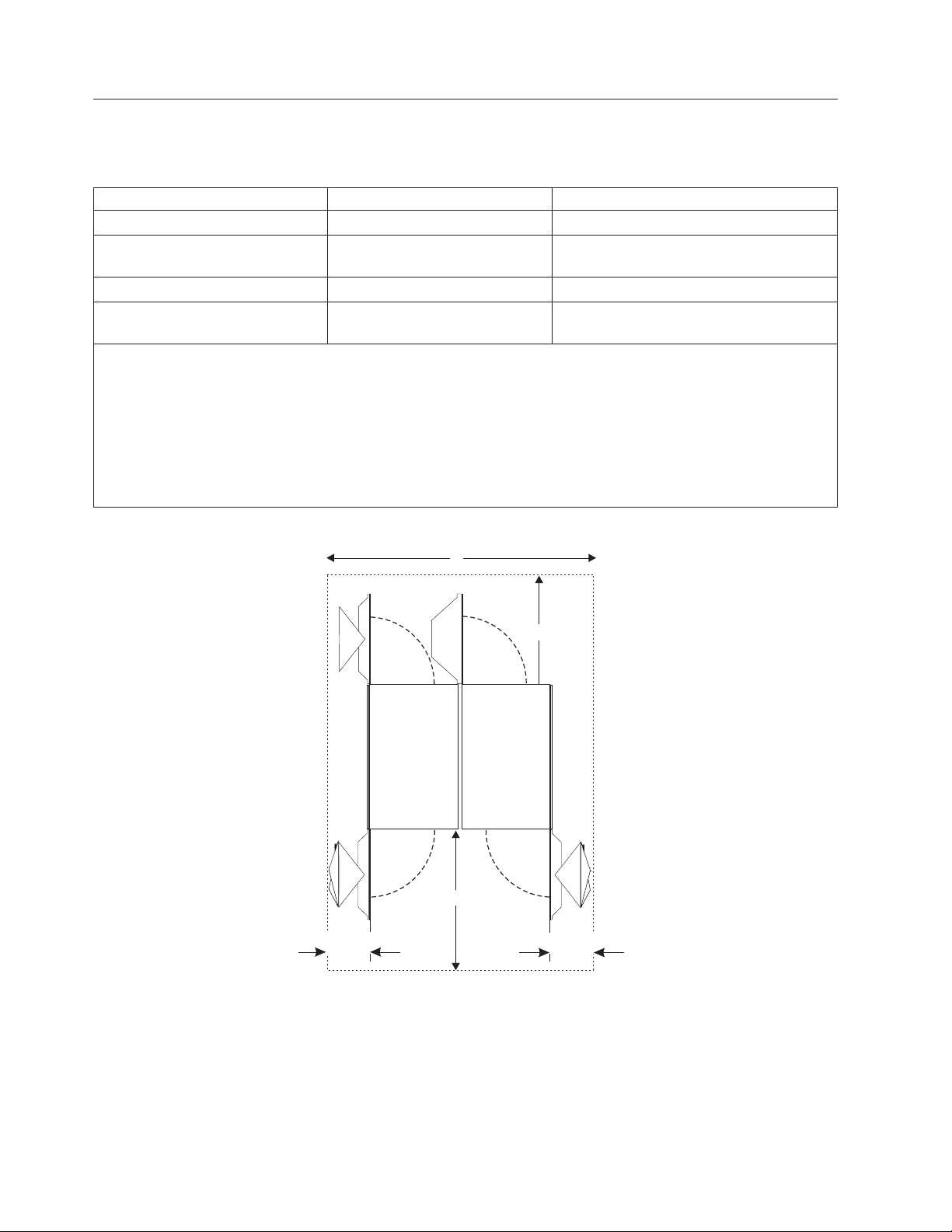
Machine and service clearance areas
Level 01f
Machine area is the actual floor space covered by the system. Service clearance area includes the machine
area, plus additional space required to open the covers for service access to the system.
A and Z frames Machine area M2/ (ft2) Service clearance area M2/ (ft2)
Radiator-cooled 2.93 (31.6) 7.64 / (82.3)
Radiator-cooled plus top exit I/O
cable towers
Water-cooled 3.09 (33.3) 7.87 / (84.8)
Water-cooled plus top exit I/O
cable towers
Notes:
1. Machine area includes installed covers.
2. Service clearance area must be free of all obstacles. Units must be placed in a way that all service areas are
accessible. The weight distribution clearance area extending beyond the service clearance area, such as the area
at the outside corners of the units, may contain support walls and columns.
3. The top exit I/O cable towers (FC 7942) are an optional feature. Service clearance not shown for these towers.
4. Front-to-front aisle spacing of at least 1168 mm (46.0 in) is required for water-cooled servers to provide
enough space in the front of the machine for fill and drain procedures.
3.45 (37.2) 7.64 / (82.3)
3.64 (39.2) 7.87 / (84.8)
g
3
3
Rear
e
Minimum Service Clearances
d = 1168 mm (46 in) - front
e = 991 mm (39 in) - rear
g = 2226.2 mm (87.7 in) - side to side
d
329.1 mm (13.0 in)
329.1 mm (13.0 in)
Front
Figure 8. Minimum service clearances
The front and rear doors access all of the serviceable area in the zEC12 server. The system requires
specific service clearances to ensure the fastest possible repair in the unlikely event that a part may need
to be replaced. Failure to provide enough clearance to open the front and rear covers will result in
extended service time.
The following describes some service clearance conditions that must be followed (See Figure 9 on page
41.)
40 zEC12 IMPP
Page 55
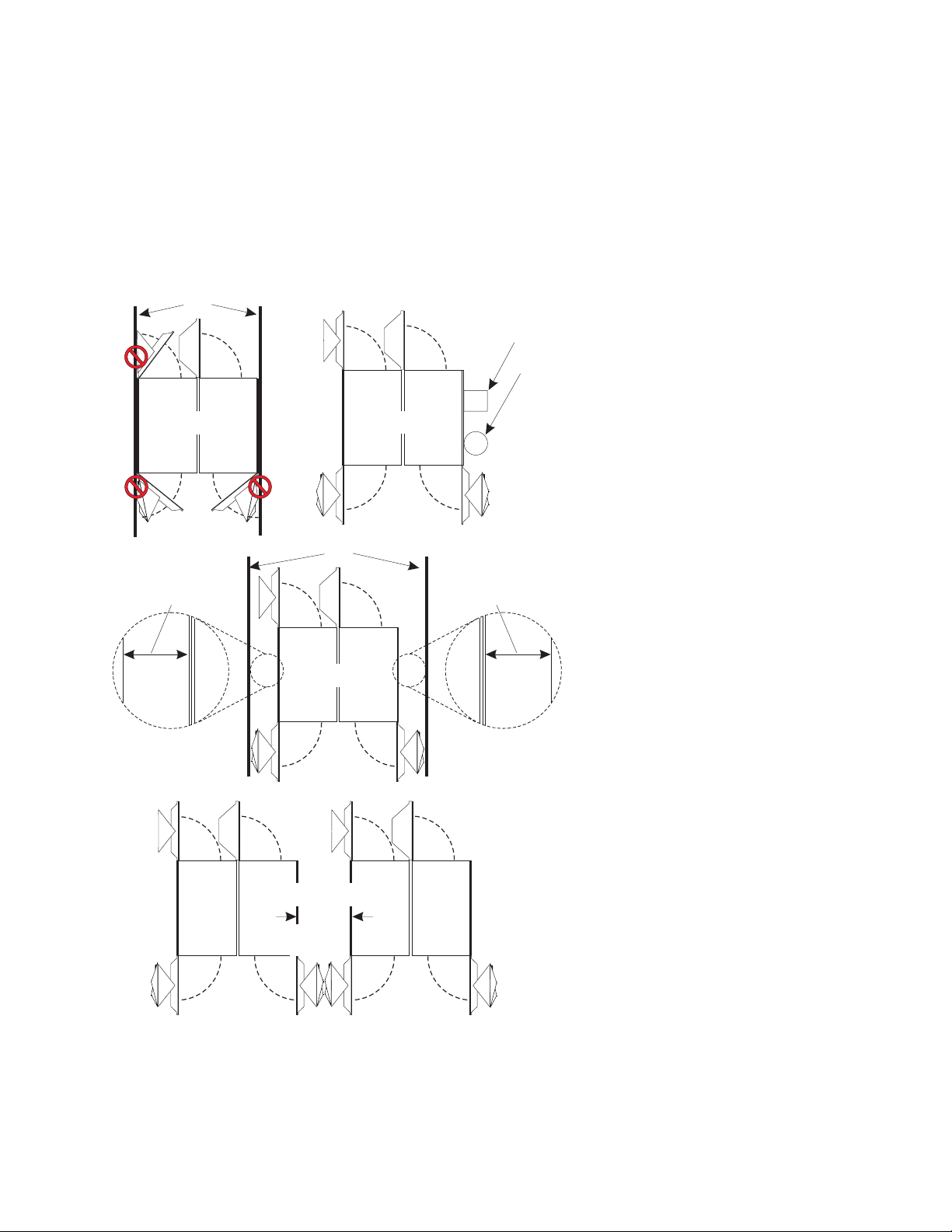
v The side cover of either an A or Z frame cannot be placed adjacent to a wall (Example A), but can be
Level 01f
positioned next to obstacles such as poles or columns (Example B).
v The front cover on frame A and both covers on frame Z open 329.1 mm (13.0 in) wider than the width
of the frame plus side cover (Example C).
v Service clearances cannot be achieved with a zEC12 server installed side-cover-to-side-cover.
Dimensions are given for zEC12 next to a zEC12. To calculate side-to-side clearance, add 329.1 mm
(13.0 in) to the clearance required from the adjacent equipment (Example D).
Wall or
other obstacle
Example A
329.1 mm (13.0 in)
frame Z to wall
OK
Example C
Wall
OK
Example B
OK
OKOK
Column
Pole
OK
329.1 mm (13.0 in)
frame A to wall
Example D
468 mm
(18.4 in)
Figure 9. Detailed service clearances
OKOK
OKOK
OKOK
Chapter 3. Models and physical specifications 41
Page 56

Cooling recommendations for the room
Level 01f
The following illustration does not represent any particular server machine type, and is intended only to
show hot and cold airflow and the arrangement of server aisles on the raised floor.
A typical zEC12 uses chilled air, provided from under the raised floor, to cool the system. As shown
below, rows of servers must face front-to front. Chilled air is usually provided through perforated floor
panels placed in rows between the fronts of servers (the cold aisles shown in the figure). Perforated tiles
generally are not placed in the hot aisles. (If your particular computer room causes the temperature in the
hot aisles to exceed limits of comfort for activities like system service, you may add as many perforated
tiles as necessary to create a satisfactory comfort level.) Heated exhaust air exits the computer room
above the computing equipment.
42 zEC12 IMPP
Page 57

Wall
Level 01f
Figure 10. System airflow
Chapter 3. Models and physical specifications 43
Page 58

The following table and chart illustrate how to determine the amount of chilled air your computer room
Level 01f
must provide to meet the environmental requirement for your zEC12.
Table 10. Cooling airflow graph codes - H20
Cooling
Model
H20 typical Radiator-cooled 5.4 - 5.4 B
H20 maximum Radiator-cooled 13.4 - 13.4 D
H20 typical Water-cooled 5.1 3.8 1.3 A
H20 maximum Water-cooled 13.1 9.8 3.3 A
Table 11. Cooling airflow graph codes - H43
Model
H43 typical Radiator-cooled 10.0 - 10.0 D
H43 maximum Radiator-cooled 19.8 - 19.8 G
H43 typical Water-cooled 9.4 7.0 2.4 A
H43 maximum Water-cooled 19.1 14.3 4.8 B
Table 12. Cooling airflow graph codes - H66
Model
H66 typical Radiator-cooled 14.2 - 14.2 F
H66 maximum Radiator-cooled 23.3 - 23.3 H
H66 typical Water-cooled 13.3 10.0 3.3 A
H66 maximum Water-cooled 22.5 16.9 5.6 B
method
Cooling
method
Cooling
method
Total power
(in kw)
Total power
(in kw)
Total power
(in kw)
Power to water
(in kw)
Power to water
(in kw)
Power to water
(in kw)
Power to air
(in kw)
Power to air
(in kw)
Power to air
(in kw)
Use cooling
curve
Use cooling
curve
Use cooling
curve
Table 13. Cooling airflow graph codes - H89
Cooling
Model
H89 typical Radiator-cooled 19.4 - 19.4 H
H89 maximum Radiator-cooled 26.9 - 26.9 I
H89 typical Water-cooled 18.4 13.8 4.6 B
H89 maximum Water-cooled 25.9 19.5 6.4 C
Table 14. Cooling airflow graph codes - HA1
Model
HA1 typical Radiator-cooled 19.4 - 19.4 H
HA1 maximum Radiator-cooled 27.6 - 27.6 I
HA1 typical Water-cooled 18.4 13.8 4.6 B
HA1 maximum Water-cooled 26.6 20.0 6.6 C
method
Cooling
method
Total power
(in kw)
Total power
(in kw)
Power to water
(in kw)
Power to water
(in kw)
Power to air
(in kw)
Power to air
(in kw)
Use cooling
Use cooling
curve
curve
44 zEC12 IMPP
Page 59

The values in the previous chart are for a typical computer room environment:
Level 01f
0
v Room inlet air = 24
|
v Customer water inlet = 14
C
0
C or cooler
v Altitude = up to 457 meters (1500 feet) above sea level.
Chapter 3. Models and physical specifications 45
Page 60

Air Flow
Level 01f
CM/M (CF/M)
198.22 (7000)
169.90 (6000)
P
O
N
M
141.58 (5000)
113.27 (4000)
84.95 (3000)
56.63 (2000)
28.32 (1000)
Under floor
temperature
Return air
temperature air-cooled
server
L
K
J
I
H
P
O
N
M
L
K
J
I
H
G
F
E
D
C
B
A
0
O
C
O
F
O
C
O
F
10 12 14 16 18 20 22 24
50.0 53.6 57.2 60.8 64.4 68.0 71.6 75.2
33.3 33.3 33.3 33.3 33.3 33.9 34.4 35.0
92 92 92 92 92 93 94 95
G
F
E
D
C
B
A
O
C
O
F
O
C
O
F
Figure 11. Cooling airflow graph
If water-cooled, return air temperature is typically between 230C and 280C depending on room ambient,
room dewpoint and actual heatload.
The proportion of server heatload removed to water is affected by the local ambient and dewpoint. For
servers operating in 22
|
75% and 90% of input power. When the ambient is below 18
between exhaust air and cooling water temperature lessens rear heat exchangers’ effectiveness. Servers
with ambient above 27
0
Cto270C ambient and under 110C dewpoint, water typically removes between
0
C are not recommended because blower speedup and warmer circuits increase
0
C, the small temperature difference
server power consumption and acoustic noise.
To maintain required cooling, it may be necessary to adjust the amount of open floor tile area to achieve
adequate air flow. “Cooling recommendations for the room” on page 42 shows that, for each zEC12, the
perforated tiles that cool that system are placed directly in front of the frame or frames, and occupy half
of the aisle between system rows. Wider aisles between system rows, allowing more perforated tile area,
may be necessary if your chilled air system cannot meet the air flow rate required to cool the system
when the aisles are too narrow.
46 zEC12 IMPP
Page 61

Beyond the specific information provided in this document, IBM recommends that the customer's facility
Level 01f
meet the general guidelines published in the American Society of Heating, Refrigeration, and Air Conditioning
Engineers (ASHRAE) Handbook.
Chapter 3. Models and physical specifications 47
Page 62

Special cooling recommendations for water-cooled machine
Level 01f
zEC12 will require four connections to the facility water, two feeds and two returns. These connections
are made using hoses that are fixed to the facility plumbing and are routed up through the rear tailgate
of the machine and terminate using quick connect couplings. Hoses and a means to fasten them to the
facility plumbing are provided with the server.
zEC12 operates from two fully redundant water control units (WCUs). These water control units each
have their own facility feed and return water connections. If water is interrupted to one of the water
control units, the other water control unit will pick up the entire load and the server will continue to
operate without interruption. Therefore each water connection to the facility plumbing must be able to
support the entire flow requirement for the system. In the event of water being lost to both water control
units, the system will attempt to reject heat using the inner door heat exchangers in each frame and
increasing system blower speeds. The server may also run in a degraded mode during this event.
Water supply
Following are some general conditions that your facility must meet prior to installation of zEC12:
v Total Hardness must not exceed 200 mg/L as calcium carbonate.
v pH must be between 7 and 9.
v Turbidity must be less than 10 NTU (Nephelometric Turbidity Unit).
v Bacteria must be less than 1000 CFUs (Colony Forming Unit)/ml.
v Water to be as free of particulate matter as feasible.
o
v Allowable system inlet water temperature range is 6
chilled water (BCW). A special water system for 2827 is typically not required.
v Required flow rate to the frame is 3.7 - 79.4 lpm (1 -21 gpm), depending on inlet water temperature
and the number of nodes populated in the server. Colder inlet water temperatures require less flow
then warmer water temperatures. Fewer nodes require less flow then maximum populated processors.
v Minimum water pressure required across the IBM hose ends is 0.34 - 2.32BAR (5 - 33.7 psi), depending
on the minimum flow required.
v Maximum water pressure supplied at the IBM hose connections to the customer water supply should
not exceed 6.89 BAR (100 psi).
v Table 17 on page 54 contains reference information to help you determine the facility water supply
conditions for your particular server.
-20oC (43o-68oF) using standard building
Supply hoses
Important:
Water hoses, hose barbs and hose clamps are shipped with the zEC12 in a kit, P/N 41U9918. Installation
of these parts is the responsibility of the customer or their designated plumbing installer and
additional materials such as plumbing fittings, valves, insulation and pipe sealant will be required. The
water hoses must be connected to the building water facility BEFORE installation of the server.
Although IBM does not make recommendations or suggestions on how to terminate the facilities side of
the hose, we do provide parts that we have used successfully in our installations. If you have other
preferred parts or termination methods, discard the parts provided with the server.
The server installer will connect the machine end of the hoses to the server. The customer or facility end
of the hose is left open to allow you or your designated plumbing installer to adjust the length and
terminate it to the appropriate fitting on the facility plumbing. For zEC12 under-floor water supply, IBM
provides:
v 2 - each 4.2 m (14 ft) hoses, (P/N 41U9739 and 2 - hoses P/N 41U9738).
48 zEC12 IMPP
Page 63

41U9739 - Hose, water supply, BLACK band
Level 01f
41U9738 - Hose, water return, WHITE band
v 4 - Stainless steel hose barbs, P/N 44V6056.
v 1 - Locating fixture, P/N 74Y1090.
44V6056 - Stainless steel hose barb
with 25.4 mm (1 in) male NPT
Server side
Side away from the server
v 4 - spare O-rings, for Aeroquip quick connect couplings, P/N 45D3158.
v 6 - Oetiker hose clamps (2 are spares) P/N 15R8650.
v 1 - Oetiker crimping tool P/N P/N 74Y0585 (Oetiker part number 14100082)
For zEC12, we strongly suggest, but do not require, shutoff valves in front of the hoses, in case there is a
need to remove the hoses for a service procedure or relocation.
Although IBM does not make recommendations or suggestions on how to terminate the facilities side of
the hose, IBM does have a released, stainless steel fitting, P/N 44V6056. This fitting is barbed on one side
and has a 25.4 mm (1 in) male NPT on the other end which can be used to connect to your facilities. For
the threaded NPT connection, IBM recommends using a thread-lock sealant (Loctite 554 creates a very
reliable connection). Since the system end of the hose assembly has a 90 degree elbow, which has to be in
a specified orientation, the locating fixture, P/N 74Y1090, provided with the system, should be used while
Chapter 3. Models and physical specifications 49
Page 64

installing the hoses . This will position the quick connects in the proper orientation, with the faces of the
Level 01f
quick connects parallel to the rear of the frame and the correct height off the floor. If the hose barb P/N
44V6056 is being used, a clamp such as an Oetiker P/N 15R8650 should be used. Six of these are
provided, four to be used for installation, and two are spares. The clamp should be slid over the hose
loosely and then the hose should be slid onto the barb until the end of the hose touches the hex flange on
the hose barb fitting.
Hose clamp
44V6056 - Stainless steel hose barb
with 25.4 mm (1 in) male NPT
Hose clamp
End of the hose should touch
the hex flange on the fitting
The clamp is then to be positioned 2 to 4 mm (.08 in to .16 in) from the edge of the hose, prior to
clamping. Oetiker clamping tool P/N 74Y0585 (their part number 14100082) must be used to crimp the
clamp (the clamp is fully crimped when the gap at the base of the crimp is 3 mm (.12 in) wide,
maximum). After installation of the hoses any exposed hose or plumbing fittings should be wrapped in
insulation to avoid condensation forming.
The organizer is removed after the hoses are connected to the facility water supply. Save the organizer for
future use in case this server should be relocated.
Water-cooled server hose connections, for the customer water supply, are located at the bottom rear of the
A frame.
50 zEC12 IMPP
Page 65

Rear view
Level 01f
A frame Z frame
U
U
U
U
Customer water hose connectors
2
1
3
4
J1
BATTERYENBLDBATTERYENBLD
(CBMustbeon)(CBMust be on)
BATTERYENBLD
(CBMustbeon)(CBMust be on)
AC/DC
AC/DC
Converter
Converter
IBM
AC/DC
AC/DC
Converter
Converter
IBM
AC/DC
AC/DC
Converter
Converter
IBM
AC/DC
AC/DC
Converter
Converter
IBM
AC/DC
AC/DC
Converter
Converter
IBM
AC/DC
AC/DC
Converter
Converter
IBM
J03
J02
J02
J01
NS
J01
J03
J02
J01
J03
J02
Pb
J1
Pb
IBFPWR
IBFPWR
/I
/0
J01
J01
unlock/offunlock/off
BPRenbld
BPRenbld
lock/on
J01
J02
J03
J04
J05
IBFPWR
IBFPWR
/0
J01
J01
unlock/offunlock/off
lock/on
IBFPWR
IBFPWR
/0
J01
J01
unlock/offunlock/off
lock/on
IBFPWR
IBFPWR
/0
J01
J01
unlock/offunlock/off
lock/on
IBFPWR
IBFPWR
/0
J01
J01
unlock/offunlock/off
lock/on
IBFPWR
IBFPWR
/0
J01
J01
unlock/offunlock/off
J04
J04
UEPO
PWR
N
N
B
B
O
O
Y
Y
R
R
P
P
M
M
A
A
A
A
S
S
L
L
S
S
CMPLT
J04
J04
lock/on
J10
SE
J09
J05J05
J07J07
J08
J06J06
.....
.....
P
P
.....
.....
W
W
R
R
.....
.....
.....
.....
STBY
STBY
J09
J06J06
J08J08
J05
J07
.....
.....
.....
.....
.....
.....
.....
.....
J09
J06J06
J08
J08
J05
J07
.....
.....
.....
.....
.....
.....
.....
.....
J06
/I
BPRenbld
BPRenbld
J07
J08
J09
J10
J12
J11
/I
J14
J13
BPRenbld
BPRenbld
J16
J15
J17
J18 J26
J17 J25
J18
J19
J20
/I
BPRenbld
BPRenbld
J21
J22
J23
J24
/I
J27
J28
BPRenbld
BPRenbld
J
J29
J30
29
J31
J32
G
GOOD
O
O
D
/I
BPRenbld
BPRenbld
J11
.....
.....
.....
.....
B
B
.....
.....
P
P
.....
.....
C
C
GOODGOOD
J10
.....
.....
.....
.....
B
B
.....
.....
P
P
.....
.....
C
C
GOOD
J10
.....
.....
.....
.....
B
B
.....
.....
P
P
.....
.....
C
C
GOOD
R
S
U
P
P
L
Y
B
L
A
C
K
E
T
U
R
N
W
H
T
E
S
R
U
E
P
T
P
U
L
R
Y
N
B
W
L
H
I
A
I
C
T
K
E
The water hoses are installed through the I/O cable tailgate at the rear of the A frame. This significantly
reduces the space available for I/O cable exit from the A frame. One option to alleviate this situation is to
consider routing some of the I/O cables from the rear of the A frame to the front of the frame. Another
possibility is top exit I/O towers. If your facility has or is considering overhead cabling, the use of top
exit I/O helps to solve the crowding of too many cables exiting the bottom of the frames.
The following illustration shows two water facilities: the upper diagram represents a typical chilled water
installation where the supply and return runs are connected to a single chilled water source. To assure
maximum, uninterrupted cooling, you may want to consider a high availability approach to the water
supply. This would mean running a pair of supply and return lines from each of two different chilled
water sources, as shown in the lower diagram. This would insure that, if one source should become
unavailable, the other would continue to cool the server, with no degradation.
Chapter 3. Models and physical specifications 51
Page 66
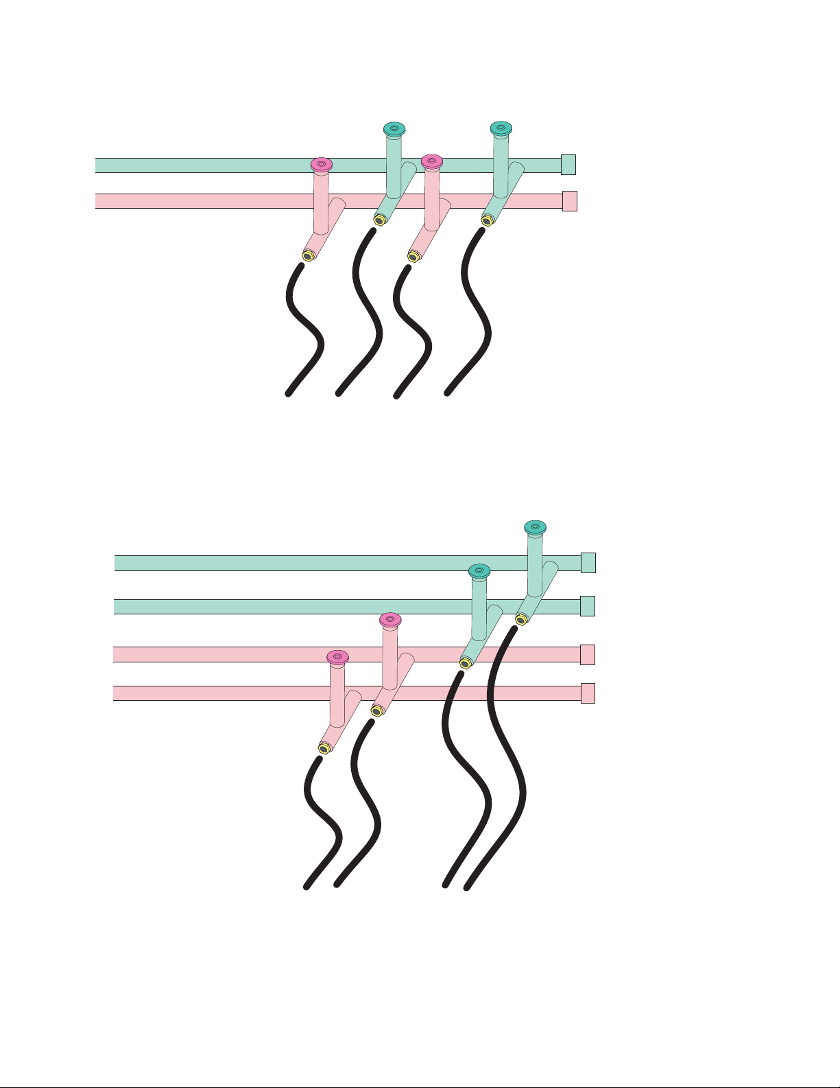
Facility chilled water supply
Level 01f
Facility chilled water return
Color of the band on the coupler
Hose Number 1 = black
Hose Number 2 = white
Hose Number 3 = black
Hose Number 4 = white
Typical customer water facility
43 21
WCU connectors
High availability customer water facility
Facility chilled water supply #1
Facility chilled water supply #2
Facility chilled water return #1
Facility chilled water return#2
Color of the band on the coupler
Hose Number 1 = black
Hose Number 2 = white
Hose Number 3 = black
Hose Number 4 = white
42 31
WCU connectors
52 zEC12 IMPP
Page 67

Materials used in the water cooling units
Level 01f
The customer side of the zEC12 WCU is comprised of the following material set. Any chemicals that are
added to the customer's chilled water must be compatible with the following materials.
Table 15. WCU materials
Description Material
Heat exchanger - plates Stainless steel
Heat exchanger - braze material Copper
Heat exchanger - hose barbs Stainless steel
Pipes and fittings - inlet and outlet pipes Stainless steel (alternate - copper)
Pipes and fittings - threaded fittings Copper
Pipes and fittings - jog Aluminum bronze alloy (being qualified by IBM materials
dept.)
Quick Connects - body castings Stainless steel
Quick Connects - external O-ring ERP (Ethylene Propylene Rubber)
Quick Connects - internal gaskets ERP (Ethylene Propylene Rubber)
Control valve - stem Stainless steel
Control valve - disc gasket Teflon
Control valve - body (tee) Red brass
Control valve - seat Bronze
Thread sealant - adhesive Loctite 554 (red)
Table 16. Water hose materials
Description Material
Aeroquip quick-connect - C-ring ERP (Ethylene Propylene Rubber)
Aeroquip quick-connect - body Stainless steel
Aeroquip quick-connect - ball Stainless steel
Aeroquip quick-connect - fitting O-ring Teflon
Aeroquip quick-connect - face seal ERP (Ethylene Propylene Rubber)
Aeroquip quick-connect - plastic face seal Polycarbonate (does not touch water)
Pig tail casting Aluminum bronze C61400
Pig tail hose - cover Carboxylated nitrile
Pig tail hose - reinforcement Synthetic, high tensile textile cord
Pig tail hose - tube Nitrile
Chapter 3. Models and physical specifications 53
Page 68

Water specifications
Level 01f
The following tables provide the requirements for the chilled water at the server connection.
Table 17. Required building chilled water conditions - (60C-130C)
Number
of nodes
Max kw
to water
Chilled water per Water
Conditioning Unit
(Water-cooled)
0
6
Building chilled water in
0
7
0
8
0
9
10
Flow (LPM) 6.0 6.3 6.6 7.0 8.0 9.0 10.0 11.5
17
Pressure Drop (Bar) 0.34 0.34 0.34 0.34 0.34 0.34 0.34 0.34
0
Outlet temp
C 23 23 23 23 23 22 22 22
Flow (LPM) 8.5 9.5 10 11 12 13.5 15 17
210
Pressure Drop (Bar) 0.34 0.34 0.34 0.34 0.34 0.34 0.34 0.34
0
Outlet temp
C 23 22 22 22 22 22 22 21
Flow (LPM) 12.5 13.5 15 16.5 18 20 22 25
314
Pressure Drop (Bar) 0.34 0.34 0.34 0.34 0.34 0.34 0.34 0.34
0
Outlet temp
C 22 22 21 21 21 21 21 21
Flow (LPM) 17 18 20 22 24 27 30 35
418
Pressure Drop (Bar) 0.34 0.34 0.34 0.34 0.34 0.35 0.37 0.50
0
Outlet temp
C 21 21 21 21 21 21 21 20
Notes:
1. Units are liters/minute, bars, and
0
C. These conditions must be available to each of the water conditioning units.
2. Temperature of water out of WCU that cools the server is dependent on measured dew point as well as building
water temperature. MCM performance is unaffected as long as dew point does not exceed 17
water does not exceed 20
in more humid environments or in cases with warm building chilled water. If building chilled water exceeds
0
20
C or room dew point exceeds 170C, the water to server temperature will continue to rise and at some point
0
C. However, the amount of heat removed by rear of frame heat exchangers is reduced
may lower processor frequency.
0
11
0
C
0
0
C and building
12
0
13
0
54 zEC12 IMPP
Page 69

Table 18. Required building chilled water conditions - (140C-200C)
Level 01f
Number
of nodes
Max kw to
water
Chilled water per Water
Conditioning Unit
(Water-cooled)
14
Building chilled water in
0
15
0
16
0
17
0
18
0
C
0
19
0
20
0
Flow (LPM) 13.5 16 20 20 20 25 25
17
Pressure Drop (Bar) 0.34 0.34 0.34 0.34 0.34 0.34 0.34
0
Outlet temp
C 21 21 21 21 22 23 24
Flow (LPM) 20 24 27 30 30 35 35
210
Pressure Drop (Bar) 0.34 0.34 0.35 0.37 0.37 0.50 0.50
Outlet temp
0
C 21 21 21 22 23 23 24
Flow (LPM) 30 33 35 40 40 42 45
314
Pressure Drop (Bar) 0.37 0.44 0.50 0.63 0.63 0.70 0.80
0
Outlet temp
C 21 21 22 22 23 24 24
Flow (LPM) 40 45 50 50 50 50 55
418
Pressure Drop (Bar) 0.63 0.80 1.0 1.0 1.0 1.0 1.2
0
Outlet temp
C 20 21 21 22 23 24 24
Notes:
1. Units are liters/minute, bars, and
2. Temperature of water out of WCU that cools the server is dependent on measured dew point as well as building
water temperature. MCM performance is unaffected as long as dew point does not exceed 17
water does not exceed 20
in more humid environments or in cases with warm building chilled water. If building chilled water exceeds
0
20
C or room dew point exceeds 170C, the water to server temperature will continue to rise and at some point
0
C. However, the amount of heat removed by rear of frame heat exchangers is reduced
0
C. These conditions must be available to each of the water conditioning units.
0
C and building
may lower processor frequency.
Attention:
IBM will supply and use a deionized (DI) water solution that is mixed with benzotriazole (BTA), a
corrosion inhibitor, for use within the system side cooling loop of water cooled products. BTA is
mixed with the deionized water to a concentration of 1000 parts per million by weight. The customer
must dispose of the water solution in accordance with applicable laws and regulations and product
characteristics at the time of disposal.
The Service Support Representative (SSR) will fill or drain the system of this solution as required for an
install, uninstall, or some maintenance procedures, such as a book replace. The Fill and Drain kit and
water container should be stored where the SSR can readily access it as needed, and it should be stored
in a climate controlled environment with the other system service tools and equipments needed to install,
service, relocate, or discontinue a system. The Fill and Drain kit is used for a water-cooled system or a
radiator-cooled system. The water container holds 15.5 – 16.0 liters (4 gallons) of deionized water mixed
with a concentration of 0.1% (900-1000 ppm) of Benzotriazole (BTA) by weight.
For detection and location reporting of potential fluid leaks, there are leak detection systems you can use
beneath a raised floor. These systems are generally used to detect leaks from glycol, condenser water, and
chilled water cooling piping, humidification feed water piping. If desired, these sensor detection systems
can be used to monitor for potential product leaks, such as the BTA water solution, which is 99.9%
deionized water.
Glycol will lower the thermal efficiency of heat exchangers. Its effect will vary by concentration and
possibly heatload. Tables provided in this documentation show how much building chilled water to
supply versus configuration for chilled water without glycol. Customers should be aware that glycol has
a diluting effect on heat transfer properties versus pure water. That means if used in a rear door heat
Chapter 3. Models and physical specifications 55
Page 70

exchanger, less heat will be removed from the exit air and, when used to cool the zEC12 WCU, the flow
Level 01f
rate must be increased when glycol is added. For example, adding 20% ethylene glycol to the building
water supply will require a 10% increase in the flow rate to maintain the same cooling level as a 0%
ethylene glycol water supply. Adding 40% ethylene glycol to the building water supply will require a
30% increase in the flow rate to maintain the same cooling level as a 0% ethylene glycol water supply.
Contact your IBM marketing specialist or installation planner if you need specific information regarding
the use of glycol in your facility.
56 zEC12 IMPP
Page 71

Considerations for multiple system installations
Level 01f
When integrating a zEC12 into an existing multiple-system environment, or when adding additional
systems to an installed zEC12, consider the following factors:
v Thermal interactions
Although computer room floor space is valuable, for optimal cooling, it is recommended that zEC12
servers have a 1168 mm (46 in) aisle between rows of systems to reduce surrounding air temperature.
See “Cooling recommendations for the room” on page 42.
v Floor placement
zEC12 must be precisely placed for the cable openings to match the floor cutouts. There is zero
tolerance for variance from the frame positioning in relation to the floor tiles.
v Floor loading
When trying to optimize floor space utilization, floor loading weight distribution rules may be
inadvertently violated by overlapping weight distribution areas of adjacent machines. Obtain the
services of a qualified structural engineer if you are uncertain of the floor load assessment for your
computer room.
Chapter 3. Models and physical specifications 57
Page 72

Level 01f
58 zEC12 IMPP
Page 73

Chapter 4. Guide for raised floor preparation
Level 01f
This chapter provides recommendations and requirements for making the necessary openings in the
raised floor for installation.
The drawings on the following pages are intended only to show relative positions and accurate
dimensions of floor cutouts. They are not machine templates and are not drawn to scale.
Raised floor cutouts should be protected by electrically non conductive molding, appropriately sized,
with edges treated to prevent cable damage and to prevent casters from rolling into the floor cutouts.
Note: For a water-cooled model on a raised floor, the height of the raised floor (subfloor to top surface of
|
floor tile) must be a minimum of 228.6 mm 9 inches) to accommodate the bend radius of the water hoses.
|
© Copyright IBM Corp. 2012, 2014 59
Page 74

Casters
Level 01f
The following illustration shows the physical dimensions around the casters. When planning for both the
movement and positioning of the system, be aware that each caster swivels in a circle slightly larger than
130 mm (5.1 in) in diameter. Exercise caution when working around floor cutouts.
Front Front
49.6 mm (1.96 in)
15.5 mm (0.6 in)
222.3 mm (8.75 in)
130.2 mm (5.17 in)
127.0 mm (5.00 in)
Swivel diameter
Radiator-cooled models
157.5 mm (6.2 in)
Caster - frame
dimensions
100.2 mm (4.00 in)
Water-cooled models
100.2 mm (4.00 in)
60 zEC12 IMPP
47.6 mm (1.87 in) 28.7 mm (1.13)
Leveling foot - frame
dimensions
100.2 mm (4.00 in)
Increased frame dimension
on water-cooled models
( 100.2 mm (4 in) )
Page 75

Procedure for cutting and placement of floor panels
Level 01f
Important:
zEC12, fully configured, can weigh in excess of 2494 kg (5500 lb). You must be certain that the raised floor on
which you are going to install the server is capable of supporting this weight. Contact your floor tile
manufacturer and a structural engineer to verify that your raised floor is safe to support the zEC12.
Depending on the floor panel type, additional panel supports (pedestals) may be necessary to maintain the
structural integrity of an uncut panel, or to restore the integrity of a cut floor panel. Consult the panel
manufacturer and the structural engineer to ensure that the panel can sustain the concentrated loads.
|
Ensure adequate floor space is available to place the frames over the floor panels exactly as shown on the
drawing.
|
Note: Frame template P/N 41T8506 can be ordered by your IBM service representative to assist in the system
layout on your raised floor.
|
DANGER: Heavy equipment — personal injury or equipment damage might result if mishandled.
(D006)
__ 1. Identify the panels needed, and list the total quantity of each panel required for the installation.
__ 2. Cut the required quantity of panels. Panels A1, A4, C1, and C4 are optional. If you have existing
equipment already installed over these panels, you do not have to cut them.
__ 3. Additional panel supports (pedestals) are recommended to restore the structural integrity of the
cut floor tile panels.
__ 4. When cutting the panels, you must adjust the size of the cut for the thickness of the edge molding
you are using. The dimensions shown are finished dimensions.
__ 5. For ease of installation, number each panel as it is cut as shown on the panel specification pages.
__ 6. Use the raised floor diagram to install the panels in the proper positions.
__ 7. You will need as many as eight uncut floor tiles to temporarily replace A1 through A4 and C1
through C4 during the physical placement of the frames. After frame placement, the uncut tiles can
be removed and the cut tiles for A1 through A4 replaced in the floor.
Chapter 4. Guide for raised floor preparation 61
Page 76

Raised floor with 610 mm (24 in) or 600 mm (23.5 in) floor panels
Level 01f
Cable exit cutouts
Rear
A
B
C
1
23
4
D
Front
545 mm
(21.5 in)
94 mm
(3.7 in)
(Panels
A2, C2)
Figure 12. Raised floor with floor panels
545 mm
(21.5 in)
(Panels
A3, C3)
110 mm
(4.3 in)
(Panels
A4, C4)
94 mm
(3.7 in)
110 mm
(4.3 in)
(Panels
A1, C1)
Frame
Entry/Exit
Front
Rear
Cutout dimensions
for raised floor
(mm) (in)
94 x 655
94 x 655
3.7 x 25.8
3.7 x 25.8
62 zEC12 IMPP
Page 77

Important:
Level 01f
Extra pedestals may be placed as shown in Figure 13:
1. Pedestals Bp1, Bp2, Bp3, Bp4, Cp1, Cp3, Cp4, and Cp6 may be placed approximately under each caster
position to prevent floor tile panels from sagging.
2. Pedestals Cp2 and Cp5 may be used to support the cut corners of floor tiles C2 and C3.
3. Pedestals Ap1, Ap2, Ap3, Ap4, Ap5, and Ap6 may be used to support the cut corners of floor tiles A1, A2, A3
and A4. Although these four tiles are not load-bearing, equipment, moving in the row where these floor
panels sit, may place high loads momentarily on the tiles.
4. If you are using either the frame tie-down features (FC 8000 or FC 8001), you may want to place additional
pedestals under the bars that rest on the floor tile panels after the features have been installed.
All of these extra pedestals are recommendations. You must decide which, if any, of these recommendations to
use.
Extra Pedestal Placement
1
23
Rear
A
Ap3
Ap1
Bp1
Ap2
Bp2
B
Z
C
Cp1
D
Front
Figure 13. Extra pedestal placement
Cp3
Cp2
Ap4
Bp3
Cp4
Ap5
A
Cp5
4
Ap6
Bp4
Cp6
All pedestals should be adjusted to just contact the underside of each floor panel before the frames are
rolled into place. Depending on your floor panel type, additional supports (pedestals) may be necessary
to restore the structural integrity of cut panels.
Chapter 4. Guide for raised floor preparation 63
Page 78

Level 01f
64 zEC12 IMPP
Page 79

Chapter 5. Power requirements
Level 01f
The zEC12 requires the following:
v System frame
– 50/60 Hz AC or high voltage DC
– Voltage ranges:
- AC: 200V to 480V AC, three-phase wiring
- DC: 380V to 520V DC
The system requires either:
– For configurations using a total of six or less Bulk Power Regulators (BPRs) - Tw o power feeds, of
the types previously described, each with the same nominal voltage. One is connected to the front of
the Z frame, and one is connected to the rear of the Z frame.
or
– For all other configurations - Four power feeds, of the types previously described, each with the
same nominal voltage. Two are connected to the front of the Z frame, and two are ocnnected to the
rear of the Z frame.
There are no power feeds to the A frame.
You cannot use a mix of DC power and AC power. The input power for the zEC12 must be
|
exclusively AC or exclusively DC.
|
Refer to the Appendix D, “3-phase dual power installation,” on page 133 for the correct wiring method
for your particular power distribution equipment.
Read the following information about Plan Ahead feature codes.
– If you choose a server that requires only two power cords, but want to be prepared for future
growth, you may order the Line Cord Plan Ahead feature (FC 2000), which ships all four line cords
regardless of the number of BPRs.
– If you expect that your server may eventually be adding additional processors or PCIe I/O drawers,
I/O drawers or I/O cages, you may want to consider the Balanced Power Plan Ahead feature (FC
3003), which adds the maximum number of Bulk Power Regulators (BPRs) to your server's power
supplies. A fully-configured server uses twelve BPRs. So, for example, if your server configuration
would only require six BPRs, the Balanced Power feature would add six more BPRs to maximize
available power. If not already included in your order, the Line Cord Plan Ahead feature would also
automatically be added along with Balanced Power. Finally, if your server is going to use the
Internal Battery Feature (IBF) (FC 3213), Balanced Power Plan Ahead will automatically supply the
maximum number of batteries, six IBFs, with your server.
– Balanced Power Plan Ahead (FC 3003) does not apply to servers using the DC power cord option.
– The Balanced Power and Line Cord Plan Ahead features give you the chance to eliminate future
service downtime when upgrading your server.
v Hardware Management Console
A single-phase feed from a customer-supplied service outlet. The outlet must provide 100V to 130V or
200V to 240V 50/60Hz single-phase AC power.
© Copyright IBM Corp. 2012, 2014 65
Page 80

Power installation considerations
Level 01f
zEC12 operates from two fully-redundant power supplies. These redundant power supplies each have
their own line cords, or pair of line cords, allowing the system to survive the loss of customer power to
either line cord or line cord pair. If power is interrupted to one of the power supplies, the other power
supply will pick up the entire load and the system will continue to operate without interruption.
Therefore, the line cord(s) for each power supply must be wired to support the entire power load of the
system.
Note: The power cord set(s) provided are for use only with this product.
For the most reliable availability, the line cords in the front (A) and the rear (B) of the Z frame should be
powered from different PDUs. The A line cord or cords exit the front of the Z frame and should be
connected to one PDU. The B line cord or cords exit the rear of the Z frame and should be connected to a
different PDU than the A cord or cords.
See Appendix D, “3-phase dual power installation,” on page 133 for examples of typical redundant
wiring facilities.
The power supplies at the front end of the system use active resistive load synthesis. Harmonic distortion
of the current waveform is small enough that it need not be considered in planning the installation. The
power factor is typically 0.95 or higher.
The utility current distribution across the phase conductors (phase current balance) depends on the
system configuration. Each front end power supply is provided with phase switching redundancy. The
loss of an input phase is detected and the total input current is switched to the remaining phase pair
without any power interruption. Depending on the configuration input power draw, the system can run
from several minutes to indefinitely in this condition. Since most single phase losses are transients which
recover in seconds, this redundancy provides protection against virtually all single phase outages.
Supply type Nominal voltage range (V) Voltage tolerance (V) Frequency range (Hz)
Two or four redundant
3-phase line cords
Two or four redundant
DC line cords
Source type Frequency Input voltage range (V) Rated input current (A)
Three-phase (60A plug) 50/60 Hz 200 - 240V 48A
Three-phase (all except 60A plug) 50/60 Hz 380 - 415V 25A
Three-phase (all except 60A plug) 50/60 Hz 480V 20A
DC N/A 380 - 520V 44A
200-480 180-509 47-63
380-520 350-550 N/A
66 zEC12 IMPP
Page 81

I/O units
Level 01f
Table 19. I/O unit descriptions and values
Feature code I/O unit description I/O unit value
4008 I/O drawer - 5 EIA units tall. Holds 8 I/O adapters installed horizontally. 1
4007 I/O cage - 14 EIA units tall. Holds 28 I/O adapters installed vertically. 2
4009 PCIe I/O drawer - 7 EIA units tall. Holds 32 I/O adapters installed vertically. 1
Chapter 5. Power requirements 67
Page 82

Line cord/bulk power regulator (BPR) specifications
Level 01f
The following tables provide number of line cords and number of BPRs required based on the number of
processor books and number of I/O units in the server configurations.
Table 20. Number of line cords required per side
3, 4
3
3
4
5
5
1
1
1
2
2
2
1
3
2
4
2
4
2
5
2
5
1
3
2
4
2
4
2
5
2
5
Number of I/O units
0123456
H20 (1 processor book) 1111111
H43 (2 processor books) 1111122
H66 (3 processor books) 1122222
H89 (4 processor books) 2222222
HA1 (4 processor books) 2222222
Note:
1. See “I/O units” on page 67 for I/O descriptions and values.
Table 21. Number of BPRs installed per side
Number of I/O units
0123456
H20 (1 processor book) 1
H43 (2 processor books) 2
H66 (3 processor books) 3
H89 (4 processor books) 4
HA1 (4 processor books) 4
1
1
1
2
2
1
1
1
3
1
3
2
4
2
4
1
2
1
3
2
4
2
4
2
4
1
2
1
3
2
4
2
4
2
4
Note:
1. Single-line power cord pair.
2. Two-line power cord pair.
3. See “I/O units” on page 67 for I/O descriptions and values.
4. Current balance on the phases is determined by the BPR count in this table. The balance (or imbalance) is
defined in Table 22 on page 69.
68 zEC12 IMPP
Page 83

Table 22. Current balance per line cord
Level 01f
1st cord set 2nd cord set
1 BPR/side unbalanced A
2 BPRs/side unbalanced B
3 BPRs/side balanced
1
2
3
—
—
—
4 BPRs/side balanced unbalanced A
5 BPRs/side balanced unbalanced B
6 BPRs/side
4
balanced balanced
Note:
1. Unbalanced A - only two phases carry equal current. The third phase carries zero.
2. Unbalanced B - two phases carry equal current. The third phase carries 1.73 times the current carried by the
other two.
3. Balanced - all phases carry the same current.
4. Only available with FC 3003 (balance power).
Table 23. Current balance Example
Example 1 - Model H20 with 1 I/O unit
From Table 21 on page 68, the number of BPRs per side = 1
From Table 22, the phase currents are unbalanced A on the first line cord set (there is no second line cord set.)
Table 24. Current balance Example
Example 1 - Model H43 with 4 I/O units
From Table 21 on page 68, the number of BPRs per side = 3
From Table 22, the phase currents are balanced on the first line cord set (there is no second line cord set.)
Table 25. Current balance Example
Example 1 - Model H66 with 3 I/O units
From Table 21 on page 68, the number of BPRs per side = 4
From Table 22, the phase currents are balanced on the first line cord set. The phase currents are unbalanced A on the
second line cord set.
Table 26. Current balance Example
Example 1 - Model H89 with 4 I/O units
From Table 21 on page 68, the number of BPRs per side = 5
From Table 22, the phase currents are balanced on the first line cord set. The phase currents are unbalanced B on the
second line cord set.
Table 27. Current balance Example
Example 1 - Model HA1 with 5 I/O units
From Table 21 on page 68, the number of BPRs per side = 5
From Table 22, the phase currents are balanced on the first line cord set. The phase currents are unbalanced B on the
second line cord set.
Chapter 5. Power requirements 69
Page 84

Power specifications
Level 01f
The following tables provide system power consumption/heat load based on the number of processor
books and number of I/O units in the server configurations. The data is shown for servers at sea level.
Real customer configurations will come out lower in the power estimator than the numbers in the table
because the table numbers represent the maximum possible configuration which is unrealistic for an
actual system. In addition, a warm room is assumed, which results in higher fan power, hopefully not the
normal situation for most installations. Finally, the numbers below assume that batteries are present and
charging.
Note: Power will be somewhat lower for DC input voltage.
As an example, a typical 4 book system in a typical data center would compute to about 17.6 kW for
radiator-cooled and 16.7 kW for water-cooled in the estimator with data from the customer's eConfig
output vs the absolute maximum of 27.6 kW for radiator-cooled and 26.6 kW for water-cooled in the
table below.
Table 28. System power consumption - Radiator-cooled
Number of I/O units
0123456
Utility power - 1 processor book 5.8 7.7 9.7 11.3 13.2 13.4 13.4
Utility power - 2 processor books 9.7 11.6 13.4 15.2 17.1 19.0 19.8
Utility power - 3 processor books 13.2 15.0 16.9 18.8 20.5 22.4 23.3
Utility power - 4 processor books 17.6 19.5 21.4 23.2 24.9 26.8 27.6
Note:
1. See “I/O units” on page 67 for I/O descriptions and values
2. Assumes maximum supported configuration (maximum I/O adapters installed)
3. The power factor is approximately unity.
4. Input power (kVA) equals heat output (kW).
5. For heat output expressed in kBTU per hour, multiply table entries by 3.41.
6. See Appendix D, “3-phase dual power installation,” on page 133 for recommendations on utility connections
which better balance the current for installations where multiple systems are connected to the same power panel.
1
70 zEC12 IMPP
Page 85

Table 29. System power consumption - Water-cooled
Level 01f
Number of I/O units
1
0123456
Utility power - 1 processor book 5.5 7.4 9.4 11.0 12.9 13.1 13.4
Utility power - 2 processor books 9.1 10.9 12.7 14.6 16.4 18.3 19.1
Utility power - 3 processor books 12.4 14.3 16.1 18.0 19.7 21.6 22.5
Utility power - 4 processor books 16.7 18.6 20.7 22.3 24.1 25.8 26.6
Note:
1. See “I/O units” on page 67 for I/O descriptions and values
2. Assumes maximum supported configuration (maximum I/O adapters installed)
3. The power factor is approximately unity.
4. Input power (kVA) equals heat output (kW).
5. For heat output expressed in kBTU per hour, multiply table entries by 3.4.
6. See Appendix D, “3-phase dual power installation,” on page 133 for recommendations on utility connections
which better balance the current for installations where multiple systems are connected to the same power panel.
7. The power advantage from using water cooling increases with the size of the system.
Chapter 5. Power requirements 71
Page 86

Power estimation tool
Level 01f
The power estimator tool for the zEC12 allows you to enter your precise server configuration to produce
an estimate of power consumption. In addition, the tool now can produce an estimate of the weight of
your server.
Log on to Resource Link at http://www.ibm.com/servers/resourcelink. Navigate to Tools, then to Power and
weight estimation. Specify the quantity for the features that are installed in your machine. This tool
estimates the power consumption for the specified configuration. The tool does not verify that the
specified configuration can be physically built.
Note: The exact power consumption for your machine will vary. The object of the tool is produce an
estimation of the power requirements to aid you in planning for your machine installation.
Actual power consumption after installation can be confirmed using the HMC Monitors Dashboard task.
Power capping
zEC12 supports power capping, which gives the customer the ability to limit the maximum power
consumption and reduce cooling requirements (especially with zBX). To use power capping, Automate
Firmware Suite (FC 0020) must be ordered. This feature is used to enable the Automate suite of
functionality associated with the IBM zEnterprise Unified Resource Manager. The Automate suite
includes representation of resources in a workload context, goal-oriented monitoring and management of
resources, and energy management. The Automate suite is included in the base zCPC at no charge for
CPs, zIIPs, and zAAPs.
72 zEC12 IMPP
Page 87

Customer circuit breakers (CBs)
Level 01f
The following table shows the maximum circuit breaker ratings based on input voltage.
Input voltage range (V) System rated current (A) Circuit breaker
208 - 240 VAC 48A 60A/63A W/T
380 - 415 VAC 25A 32A W/T
480 VAC 20A 30A
380 - 520 VDC 44A 60A DC/63A DC W/T
It is recommended, for simplicity and ease of upgrades, that the circuit breaker ratings in this table be
used on all power cords for all installations. The actual power drawn (heat load) by any configuration
will not be affected.
Note: System z server design incorporates Electromagnetic Interference filter capacitors required to block
electrical noise from penetrating the power grid. A characteristic of filter capacitors, during normal
operation, is high leakage currents. Depending on the server configuration, this leakage current can reach
350mA (350 milliamps). For most reliable operation, Ground Fault Circuit Interrupter (GFCI), Earth
Leakage Circuit Breaker (ELCB) or Residual Current Circuit Breaker (RCCB) type circuit breakers are
not recommended for use with System z servers. By internal design and grounding, System z servers
are fully certified for safe operation (compliance with IEC, EN, UL, CSA 60950-1).
However, if leakage detection circuit breakers are required by local electrical practice, the breakers
should be sized for a leakage current rating not less than 500mA in order to reduce the risk of server
outage caused by erroneous and spurious tripping.
Chapter 5. Power requirements 73
Page 88

Internal battery feature (FC 3213)
Level 01f
The Internal Battery Feature (IBF) (FC 3213) is optional on the zEC12. In the event of input power
interruption to the system, the internal battery feature will provide sustained system operation for the
times listed in the following table.
Table 30. IBF holdup times
Number of I/O units
0123456
1
1 processor node 7.7 min
5.0 min
2 processor nodes 9.7 min113.6 min111.0 min
3 processor nodes 11.1 min19.3 min
4 processor nodes 7.6 min
2
6.8 min
Note:
1. Single-line power cord pair.
2. Two-line power cord pair.
3. The holdup times in this table are valid for batteries 3 years old or less that have seen normal service life (2 or
less complete discharges per year) with the system input power at N+1 operation.
4. Batteries are only connected to the Bulk Power Regulators associated with the section 1 power cords.
5. These holdup times are estimates. Your particular battery holdup time for any given circumstance may be
different.
6. Holdup times vary depending on the number of BPRs installed. As the number of BPRs increases, the holdup
time also increases until the maximum number of BPRs is reached. Once six BPRs (three per side) are installed
no additional batteries are added so the time decreases from that point.
1
1
2
4.0 min
8.0 min
6.1 min
1
7.9 min111.9 min111.0 min111.0 min
1
2
2
9.1 min
7.1 min
5.0 min
1
2
2
7.9 min
6.4 min
4.4 min
1
2
2
7.0 min
5.2 min
4.0 min
2
2
2
6.7 min
4.9 min
3.8 min
1
2
2
2
74 zEC12 IMPP
Page 89
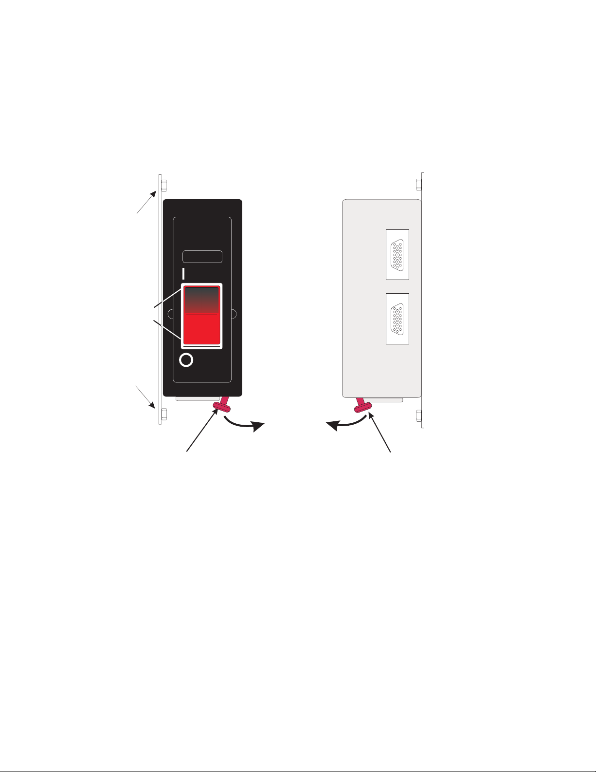
Unit emergency power off (UEPO)
Level 01f
There is a unit emergency power off (UEPO) switch on the front of the primary frame (A frame) of each
system. When tripped, the UEPO switch will immediately disconnect utility and battery power from the
machine functional unit. Utility power is confined to the machine power compartment. All volatile data
will be lost.
Unit EPO Panel
Mounting Screw
Unit EPO
Switch
Unit EPO Panel
Mounting Screw
Front View
Unit EPO Panel
BYPASS ACTIVE
Rear View
Unit EPO Panel
A Side
BPI
Cable
J01
B Side
BPI
Cable
J02
Customer
Supplied
Cable
J03
ACTIVE BYPASS
Room Disconnecting Means/
Emergency Power Off Actuator
Figure 14. UEPO panels
Room Disconnecting Means/
Emergency Power Off Actuator
Figure 14 illustrates both the front and the rear of the machine UEPO panel. The rear view shows where
the room electrical power disconnecting means, or room Emergency Power Off, EPO, cable plugs into the
machine. Notice the switch actuator. Once moved to make the cable connection possible, the room
disconnecting means / EPO cable must be installed for the machine to power on.
Chapter 5. Power requirements 75
Page 90
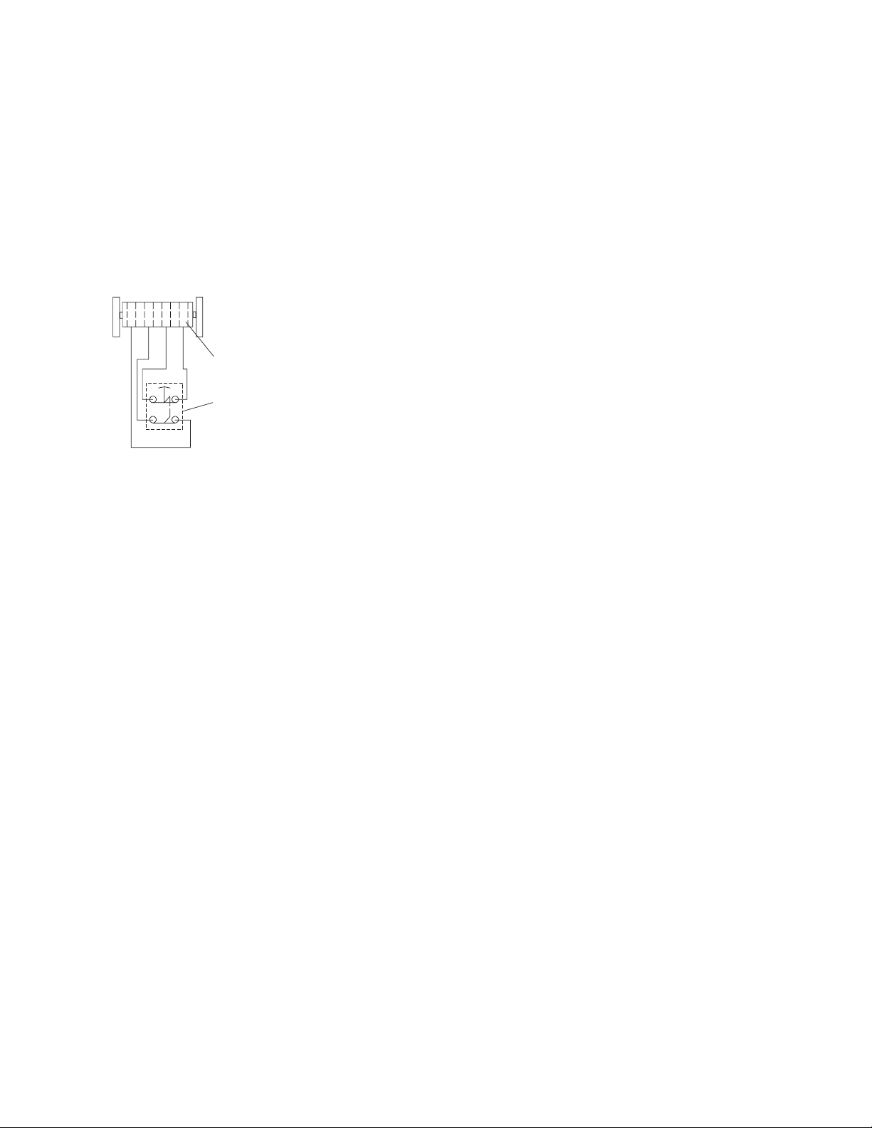
Computer room emergency power off (EPO)
Level 01f
When the internal battery backup feature is installed and the room disconnecting means / EPO is
tripped, the batteries will engage and the computer will continue to run. It is possible to attach the
computer room disconnecting means / EPO system to the machine UEPO switch. When this is done,
tripping the room disconnecting means / EPO will disconnect all power from the line cords and the
internal battery backup unit. In this event all volatile data will be lost.
To incorporate the IBF into the room disconnecting means / Emergency Power Off (EPO) systems, a cable
must be made to connect to the back of the system UEPO panel. The following diagram illustrates how
this connection is made.
4321
Room UEPO Switch Schematic
Figure 15. UEPO switch schematic
AMP Part Number -- 770019-1
Contact Number
2 Pole Normally-closed Pushbutton
In Figure 15, an AMP connector 770019-1 is needed to connect to the system UEPO panel. For room
disconnecting means / EPO cables using wire sizes #20 AWG to #24 AWG use AMP pins part number
770010-4. The permissible resistance of the customer connection is 5 Ohms Maximum (~200' of #24 AWG).
76 zEC12 IMPP
Page 91
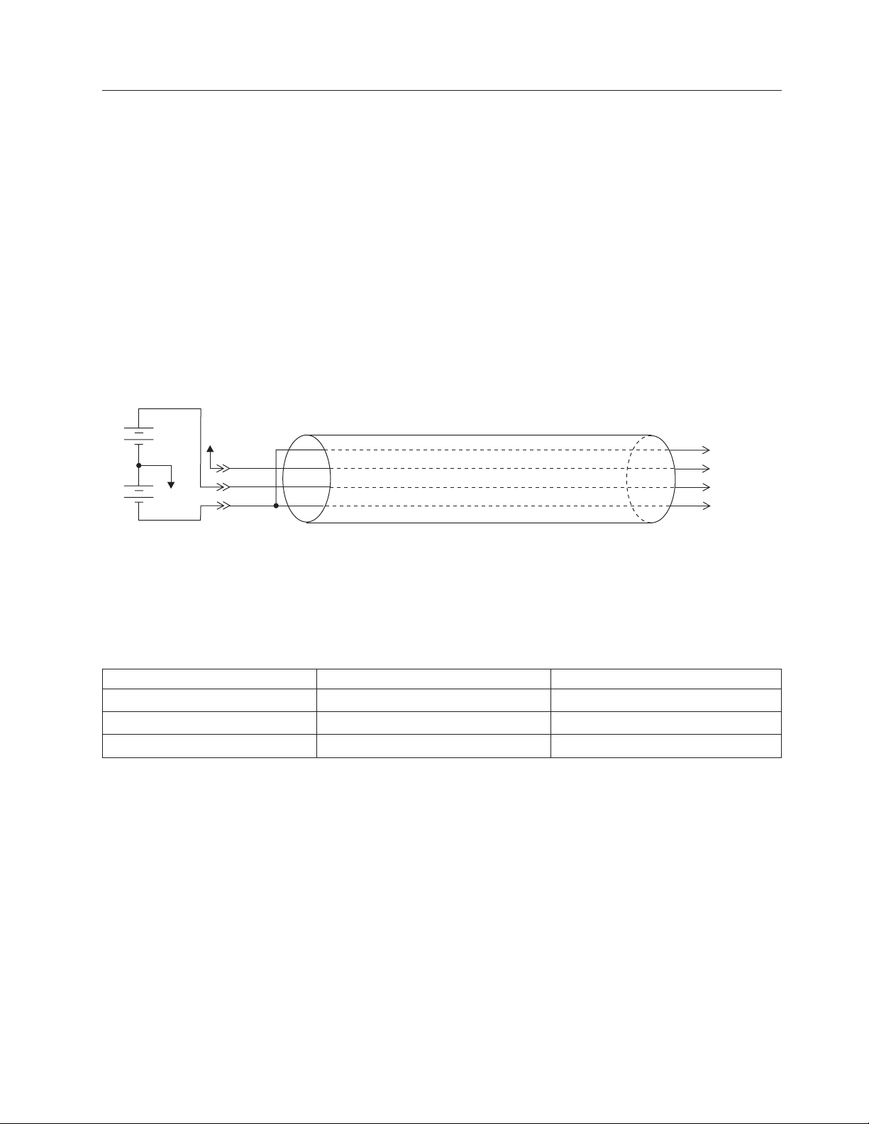
Power plugs and receptacles
Level 01f
Plugs are shipped with the machine line cords in USA and Canada. The line cord length is 4250 mm (14
ft). Power plugs in the following table are approved for use with specified models and meet the relevant
test laboratory or country/test-house standards. The power plug must be connected to a correctly wired
and grounded receptacle. The customer is responsible for receptacle wiring.
For countries that require other types of plugs or receptacles, the system is shipped without plugs on the
line cords, and you are responsible for supplying and installing both plugs and receptacles.
Important:
In a typical three-phase power cord, there are five wires inside the cut cord cable. There are the three
phase wires, one ground wire and there is a fifth, small diameter wire, connected to the cable shield, that
acts as a drain. This drain wire must be connected to the cable ground, NOT neutral.
DC power cord
The DC power cord is illustrated below.
Vdc2
Vdc1
Earth
Earth
GND
plus
minus
C
GND
B
A
Customer
DC source
DC Line cord
Machine plug
The DC feed is on the B line. The C and A lines are the DC return. The crimp between the C line and A
line is internal on cords with a customer plug. For cut end cords, the C and A lines must both be tied to
the negative side of the source because all four wires exit the cord body separately. Reference the
following table for DC voltage information.
Table 31. Input voltage range
Parameter Absolute maximum Absolute minimum
Vdc1 + Vdc2 550V 330V
Vdc1 550V 0V
Vdc2 420V 0V
Chapter 5. Power requirements 77
Page 92

Table 32. Supported power cords
Level 01f
System location
USA, Canada, Japan
(200-240 VAC)
USA, High Voltage
(480 VAC)
USA, Canada
|
(380-415 VAC)
World Trade
(208-240 VAC)
World Trade
(380-415 VAC)
Supported power cord
feature codes
8952
8955
8993
8950
8983
8976
8977
8949
8982
8996
8951
8988
8998
3
Watertight plug Watertight receptacle
60A IEC-309
(provided as part of the cord)
30A IEC-309
(provided as part of the cord)
30A IEC-309
provided as part of the cord)
No plug provided.
Cut end cord.
Plug is provided by the customer
and is electrician-installed.
No plug provided.
Cut end cord.
Plug is provided by the customer
and is electrician-installed.
4
60A IEC-309 460R9W
(not provided)
30A IEC-309 430R7W
(not provided)
30A HBL430R6V02
(not provided)
(not specified)
(not specified)
USA, Canada, Japan
(380-520 VDC)
World Trade
(380-520 VDC)
8947
8953
8963
8948
8965
60A
(provided as part of the cord)
No plug provided.
Cut end cord.
Plug is provided by the customer
and is electrician-installed.
360R8WDC
(not provided)
(not specified)
Notes:
1. IBM continues to strongly recommend the use of a metal backbox (example shown below) with our
line cords using IEC-309 plugs. Although in-line connectors and nonmetallic backboxes are available
and compatible, they are not recommended. These recommendations are based on the metal backbox
providing:
v An added level of protection against a mis-wired phase and ground reversal
v In some cases, a metal backbox may be better for EMI mitigation
You may choose not to use a metal backbox. In this case, please check your local code for specific
requirements.
2. The customer must obtain the appropriate plugs and receptacles, based on existing electrical codes,
where those plugs and receptacles are not provided with the system.
3. See “Line cord wire specifications” on page 83 for descriptions of the power cord feature codes.
78 zEC12 IMPP
Page 93

4. This plug is dual listed at 30A and 32A.
Level 01f
|
Chapter 5. Power requirements 79
Page 94

Grounding specifications
Level 01f
Every three-phase circuit must contain three-phase conductors and an insulated equipment-grounding
conductor. Every single-phase 120 volt branch circuit (used for the Hardware Management Console and
service outlets) must contain one phase conductor, a neutral conductor, and an insulated
equipment-grounding conductor.
For 208 VAC through 240 VAC installations worldwide, the equipment-grounding conductor must match
local electrical codes and must be green with or without one or more yellow stripes on the insulation.
IBM recommends that the ground wire be the same size as the phase conductor wires.
Conduit must not be used as the only grounding means. However, any conduit or cable shield must be
connected at both ends in such a way that it is included in the grounding path in parallel with the
grounding conductor it contains. Most electrical codes require that branch circuit wiring be located in
metallic conduit, or be made from shielded cable, if located under a raised floor. Even when not required
by local regulations, some form of shield around the branch circuit wiring is strongly recommended as a
means of reducing coupling of high-frequency electrical noise into signal and control cables.
For information about additional recommendations and requirements for equipment grounding, go to
Resource Link (http://www.ibm.com/servers/resourcelink). See General Information for Planning a
Physical Site.
80 zEC12 IMPP
Page 95
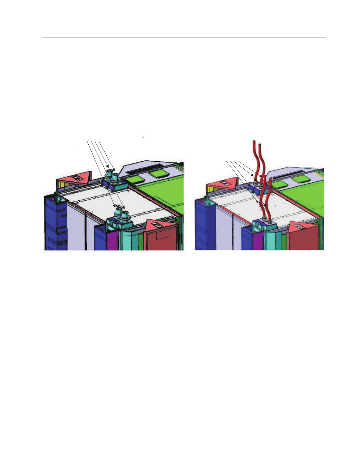
Top exit power cords
Level 01f
zEC12 has the option of top exit power cord cabling. There are several power cord options specifically
made for top exit, and you must chose one of these if you want to have the power cords exit through the
top of the server. The top exit power cords are manufactured with additional hardware that mounts the
cord to the frame of the machine and provides an EMC seal at the same time.
For power cord top exit, choose from the following power cord feature codes: 8947, 8948, 8949, 8950,
8951, 8952, 8953, 8955, and 8977.
For feature codes 8947, 8952, 8953, and 8955, these 60 amp IBM cords end directly at the top of the frame.
Therefore, your cords must be long enough to reach the frame. See Figure 16.
plugged 60 amp connections
cut cords or 30 amp cords
A frame
Z frame
Figure 16. Top exit power cords - plugged 60 amps connection, cut cord or 30 amp cord connection
Z frame
A frame
For feature codes 8948, 8949, 8950, 8951, and 8977, your receptacle must drop to within 305 mm (1 ft) of
the top of the frame and be no further than 305 mm (1 ft) from the front door or side cover of the frame.
(See Figure 17 on page 82 and Figure 16.
Chapter 5. Power requirements 81
Page 96
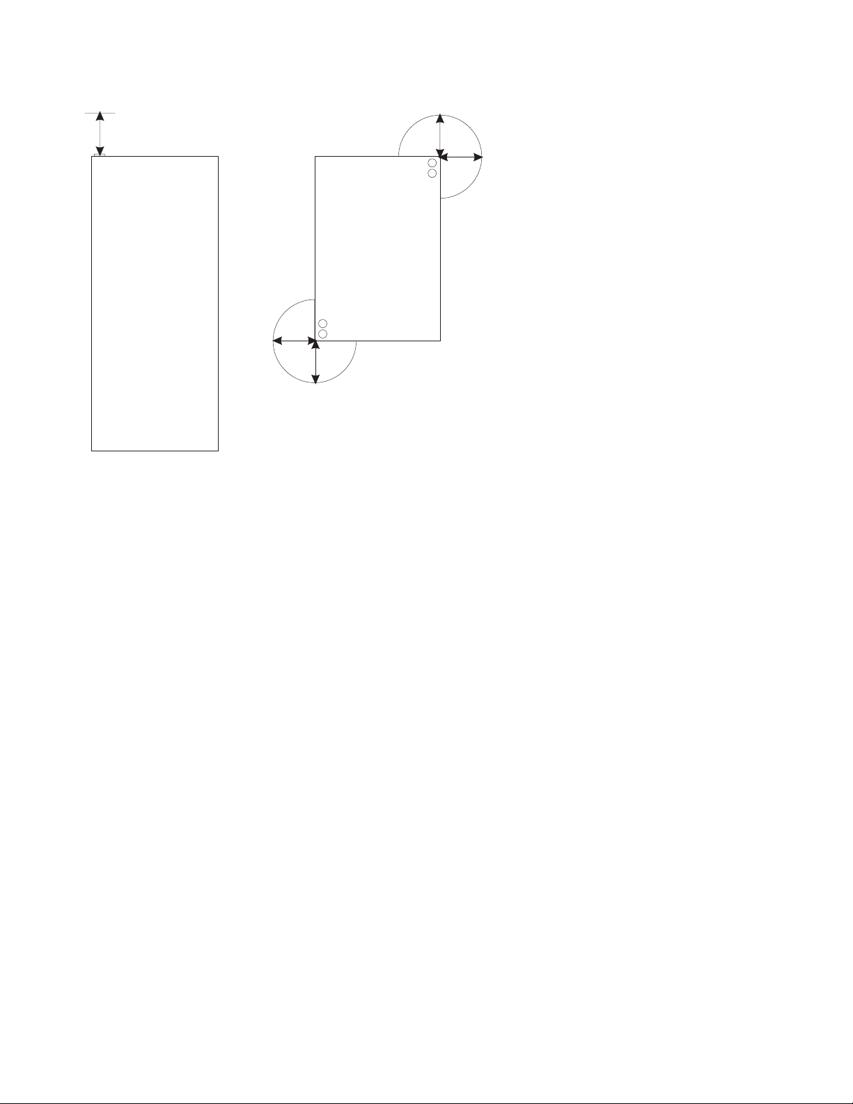
305 mm (1 ft)
Level 01f
305 mm (1 ft)
Front view
305 mm (1 ft)
Figure 17. Receptacles for top exit power cords
Top view
82 zEC12 IMPP
Page 97

Line cord wire specifications
Level 01f
Line cord usage location Feature code AWG # / type
USA, Canada, Japan
(380-520 VDC) 60A
top exit cord
ends at top of rack
World Trade
(380-520 VDC)
cut top exit cord
14 ft
World Trade, low voltage
cut top exit cord
14 ft
USA
(480 VAC) 30A
top exit cord
6ft
World Trade, high voltage
cut top exit cord
14 ft
USA, Canada, Japan
(200 VAC) 60A
top exit cord
ends at top of rack
USA, Canada, Japan
(380-520 VDC) 60A
top exit cord
ends at top of rack
USA, Canada, Japan
(200 VAC) 60A
top exit cord
ends at top of rack
USA, Canada, Japan
(380-520 VDC) 60A
bottom exit cord
14 ft
World Trade
(380-520 VDC)
bottom exit cord
14 ft
USA, Canada
(380-415 VAC) 30A
bottom exit cord
14 ft
USA, Canada
(380-415 VAC) 30A
top exit cord
6ft
8947
8948
8949
8950
8951
8952
8953
8955
8963
8965
8976
8977
#6 AWG
Type PPE
#6 AWG
Type PPE
#6 AWG
Type PPE
#10 AWG
Type ST
#10 AWG
Type ST
#6 AWG
Type PPE
#6 AWG
Type PPE
#6 AWG
Type PPE
#6 AWG
Type PPE
#6 AWG
Type PPE
#10 AWG
Type ST
#10 AWG
Type ST
Number of
shields
1 (overall gross
shield)
1 (overall gross
shield)
1 (overall gross
shield)
1 (overall gross
shield)
1 (overall gross
shield)
1 (overall gross
shield)
1 (overall gross
shield)
1 (overall gross
shield)
1 (overall gross
shield)
1 (overall gross
shield)
1 (overall gross
shield)
1 (overall gross
shield)
Connector
supplied
Yes 28.5 (1.12)
No 28.5 (1.12)
No 28.5 (1.12)
Yes 18.54 (0.73)
No 18.54 (0.73)
Yes 28.5 (1.12)
Yes 28.5 (1.12)
Yes 28.5 (1.12)
Yes 28.5 (1.12)
No 28.5 (1.12)
Yes 18.54 (0.73)
Yes 18.54 (0.73)
Bulk outside
diameter mm
(in)
Chapter 5. Power requirements 83
Page 98

Line cord usage location Feature code AWG # / type
Level 01f
World Trade, low voltage
(200-240 VAC)
bottom exit cord
14 ft
USA, high voltage
(480 VAC) 30A
bottom exit cord
14 ft
World Trade, high voltage
(380-415 VAC)
bottom exit cord
14 ft
USA, Canada, Japan
(200-240 VAC) 60A
bottom exit cord
14 ft
World Trade, low voltage
(200-240 VAC)
bottom exit cord
14 ft
low smoke, halogen-free
World Trade, high voltage
(380-415 VAC)
bottom exit cord
14 ft
low smoke, halogen-free
Note:
1. Where plugs are provided, Hubbell is the plug supplier.
2. If you choose to use a Hubbell receptacle, do NOT use the Hubbell C-Series Light Industrial
3. The customer must obtain the appropriate plugs and receptacles, based on existing electrical codes, where those
plugs and receptacles are not provided with the system.
4. The power cord set(s) provided are for use only with this product.
5. FCs 8952 and 8955 are for top exit connections to a 200 to 240 VAC source in the US, Canada and Japan. They
have IEC-309 60A AC plugs hard connected to the top of the frame. They are coordinated as follows:
v For systems requiring 2 cords, order FC 8952.
v For systems requiring 4 cords (or plan ahead to 4 cords), order both 8952 and 8955.
v For an upgrade from a system with 2 cords to a system requiring 4 cords, order 8955.
6. FCs 8947 and 8953 are for top exit connections to a 380 to 520 VDC source in the US, Canada and Japan. They
have IEC-309 60A DC plugs hard connected to the top of the rack. They are coordinated as follows:
v For systems requiring 2 cords, order FC 8947.
v For systems requiring 4 cords (or plan ahead to 4 cords), order both 8947 and 8953.
v For an upgrade from a system with 2 cords to a system requiring 4 cords, order 8953.
8982
8983
8988
8993
8996
8998
#6 AWG
Type DP-1
#10 AWG
Type DP-1
#10 AWG
Type DP-1
#6 AWG
Type PPE
#6 AWG
Type LSZH
#10 AWG
Type LSZH
Number of
shields
1 (overall gross
shield)
1 (overall gross
shield)
1 (overall gross
shield)
1 (overall gross
shield)
1 (overall gross
shield)
1 (overall gross
shield)
Connector
supplied
No 28.5 (1.12)
Yes 14.48 (0.57)
No 14.48 (0.57)
Yes 28.5 (1.12)
No 25.91 (1.02)
No 15.00 (0.59)
Bulk outside
diameter mm
(in)
84 zEC12 IMPP
Page 99

Wire colors for cut-end three-phase alternating current cords
Level 01f
Wire Number Color Description
Line 1 Brown Phase 1 (labeled "PH-1" on the wire insulation
Line 2 Black Phase 2 (labeled "PH-2" on the wire insulation
Line 3 Gray Phase 3 (labeled "PH-3" on the wire insulation
Ground Green/Yellow Ground (labeled "GND" on the wire insulation
Drain clear or uninsulated Cable shield - must be connected to GROUND
Wire colors for cut-end direct current cords
Wire Number Color Description
Line 1 Black (labeled "-" on the wire insulation
Line 2 Red (labeled "+" on the wire insulation
Line 3 Black (labeled "-" on the wire insulation
Ground Green/Yellow Ground (labeled "GND" on the wire insulation
Drain clear or uninsulated Cable shield - must be connected to GROUND
Line physical protection
In US installations, the line cord must meet National Electric Code (NEC) requirements. When line cords
are run on the surface of the floor, they must be protected against physical damage. (See NEC 645-5.) For
other countries, local codes apply.
Service outlet (customer-supplied)
A duplex service tool outlet should be installed within 1.5 m (5 ft) of the system frame. The power
requirement is 110V/120V for USA and Canada (other power requirements are country dependent). The
service tool outlets should be fed from the same power source as the system. The service tool outlet
should be placed on a separate circuit breaker so it can be used when the processor frame circuit breaker
is off.
Chapter 5. Power requirements 85
Page 100

Level 01f
86 zEC12 IMPP
 Loading...