

Page 1

Personal
Hardware
Library
Computer
Reference
Guide
to
Operations
68x2523
Page 2

The
warranty
U.S.
and
supplier.
Puerto
Please
terms
and
Rico)
retain
conditions
for
an
them
applicable
IBM
Personal
with
your
Computer
proof
of
in
the
country
product
purchase.
of
purchase
are
available
(except
for
from
the
the
Limited
The
International
Product
from
IBM
be
in
good
repair
or
except
exchange
will
become
damage
modification
Limited
warranty
Service/Exchange
purchase
the
claim.
the
risk
location
IBM
Personal
P.O.
Box
ALL
EXPRESS
THE
WARRANTIES
PARTICULAR
DAYS
EXPRESS
NOT
ALLOW
SO
THE
IF
THIS
ABOVE,
PROVIDED
DAMAGES,
INCIDENTAL
OR
INABILITY
IBM
PERSONAL
POSSIBILITY
PARTY.
Warranty
be
in
good
or
an
Authorized
working
this
set
forth
basis
and
the
property
the
Product
of
the
period
to
from
IBM
If
this
Product
loss
or
to
use
Computer
1328,
Boca
AND
PURPOSE,
THE
OR
IMPLIED,
LIMITATIONS
ABOVE
PRODUCT
YOUR
ABOVE.
INCLUDING
OR
TO
OF
Business
order
Product
below.
will
Product.
service
an
Center
or
damage
the
DATE
LIMITATIONS
SOLE
CONSEQUENTIAL
COMPUTER
SUCH
to
replace
as
to
Warranty
of
and
FROM
working
Authorized
an
Raton,
IMPLIED
OF
IS
USE
(U.S.
Machines
IBM
during
Service
be
either
of
IBM.
resulting
may
in
Authorized
is
delivered
in
original
Dealer
MERCHANTABILITY
OF
WILL
NOT
REMEDY
IN
NO
LOST
SUCH
DAMAGES,
Corporation
order
for a period
Personal
this
90-day
in
the
United
parts
reconditioned
This
from
accident,
be
obtained
IBM
the
United
IBM
transit,
by
to
shipping
or
write
Florida
33429-1328,
WARRANTIES
ARE
LIMITED
PURCHASE,
APPLY
ON
HOW
MAY
IN
GOOD
SHALL
EVENT
PROFITS,
PRODUCT,
DEALER
and
warrants
of
Computer
warranty
States
and
limited
Personal
States
mail,
prepay
container
to
WILL
OR
and
replacement
or
new.
warranty
disaster,
by
delivering
Computer
and
Personal
you
shipping
or
IBM
Personal
for
FOR
IN
DURATION
AND
AFTER
LONG
NOT
APPLY
WORKING
BE
REPAIR
IBM
LOST
DAMAGES
EVEN
HAS
BEEN
FOR
ANY
Puerto
this
90
Dealer.
period,
Puerto
Puerto
Computer
agree
equivalent.
further
AND
NO
THIS
AN
ORDER
BE
SAVINGS
Personal
days
from
Should
IBM
Rico
Products
All
replaced
does
not
misuse,
abuse,
the
Product
dealer,
Rico. A dated
Dealer
to
insure
charges
to
Computer,
information.
THIS
PRODUCT,
FITNESS
TO A PERIOD
WARRANTIES,
PERIOD.
IMPLIED
TO
YOU.
AS
OR
REPLACEMENT
LIABLE
ARISING
IF
IBM
OR
ADVISED
CLAIM
Rico)
Computer
the
date
this
Product
will,
at
at
no
additional
will
be
furnished
parts
include
service
or
non-IBM
during
or
any
IBM
proof
must
the
Product
the
warranty
Contact
Sales
FOR
A
SOME
WARRANTY
WARRANTED
TO
YOU
OR
OTHER
OUT
OF
AN
AUTHORIZED
OF
THE
BY
ANY
of
purchase
fail
its
option,
charge
on
and
Products
to
repair
the
90-day
of
accompany
or
assume
service
an
Authorized
and
Service,
INCLUDING
OF
90
WHETHER
STATES
LASTS,
AS
FOR
ANY
THE
USE
OTHER
to
an
DO
OF
SOME
STATES
INCIDENTAL
SO
THE
THIS
WARRANTY
ALSO
HAVE
FOR
WARRANTY
THIS
PRODUCT
COMPUTER
SERVICE/EXCHANGE
ABOVE
OTHER
DEALER
DO
OR
CONSEQUENTIAL
LIMITATIONS
SERVICE
BE
NOT
ALLOW
GIVES
YOU
RIGHTS
RETURNED
FROM
CENTER
THE
OR
EXCLUSIONS
SPECIFIC
WHICH
OR
ASSISTANCE,
TO
WHOM
IN
EXCLUSION
DAMAGES
LEGAL
MAY
THE
AUTHORIZED
IT
WAS
THE
UNITED
OR
FOR
MAY
RIGHTS,
VARY
EROM
IT
IS
RECOMMENDED
PURCHASED
STATES
LIMITATION
CONSUMER
NOT
APPLY
AND
STATE
IBM
PERSONAL
OR
TO
OR
PUERTO
OF
PRODUCTS,
TO
YOU
MAY
TO
STATE.
THAT
ANY
YOU.
o
IBM
RICO.
Page 3
Personal
Hardware
Library
Computer
Reference
Guide
to
Operations
Page 4

First
Edition
The
following
where
such
BUSINESS
"AS
IMPLIED,
WARRANTIES
PARTICULAR
implied
apply
provisions
MACHINES
IS"
WITHOUT
INCLUDING,
warranties
to
you.
(August
paragraph
does
are
WARRANTY
OF
MERCHANTABILITY
PURPOSE.
in
certain
1986)
not
apply
OF
NOT
states
to
with
ANY
LIMITED
inconsistent
CORPORATION
BUT
Some
transactions,
the
United
local
do
therefore,
Kingdom
law:
INTERNATIONAL
PROVIDES
KIND,
TO,
OR
FITNESS
not
allow
this
or
any
THIS
EITHER
THE
disclaimer
PUBLICATION
EXPRESS
IMPLIED
FOR
statement
country
A
of
express
may
n
OR
or
not
This
publication
Changes
incorporated
and/or
publication
It
about,
are
construed
programming,
Requests
Personal
Computer
©
are
periodically
changes
at
is
possible
not
that
IBM
products
announced
to
for
Computer
Dealer
Copyright
in
any
mean
or
copies
International
could
include
new
editions
in
the
product(s)
time.
this
publication
(machines
in
your
that
IBM
services
of
this
products
or
your
technical
made
to
the
of
information
the
publication.
and/or
may
and
country.
intends
in
your
programs),
Such
to
country.
publication
should
IBM
Business
be
Marketing
Machines
inaccuracies
the
contain
herein;
IBM
program(s)
reference
programming,
references
announce
and
made
such
for
technical
to
your
Representative.
Corporation
or
typographical
these
may
changes
make
improvements
described
to,
or
information
or
or
information
IBM
services
products,
information
authorized
IBM
1986
errors.
will
in
this
must
about
Personal
be
that
not
IBM
be
n
Page 5
The
following
indicated
statement
by
the
FEDERAL
FREQUENCY
applies
to
information
all
referring
COMMUNICATIONS
INTERFERENCE
IBM
to
that
Personal
Computer
product.
COMMISSION
STATEMENT
products
unless
otherwise
RADIO
Warning;
limits
Part
15
devices,
Class B limits
computer
with
noncertified
radio
This
equipment
for a Class B computing
of
FCC
rules.
terminals,
is
operated
printers,
may
be
peripherals
and
TV
reception.
INSTRUCTIONS
This
equipment
properly,
and
the
tested
and
with
Subpart J of
protection
guarantee
does
cause
equipment
more
of
• Reorient
• Relocate
• Move
• Plug
different
generates
that
is,
in
service
that
the
the
strict
manual,
found
to
comply
Part
against
such
interference
interference
off
and
on,
following
the
receiving
the
computer
the
computer
computer
branch
and
accordance
may
15
of
interference
to
radio
the
user
measures:
away
into a different
circuits.
has
been
certified
device,
Only
peripherals
etc.)
certified
attached
in a residential
TO
USER
uses
cause
with
the
FCC
rules,
will
not
or
is
encouraged
antenna.
with
respect
from
to
this
environment.
is
likely
to
radio
frequency
with
the
interference
limits
for a Class B computing
which
in a residential
occur
in a particular
TV
reception,
to
the
receiver.
outlet
energy
operating
to
radio
are
designed
installation.
which
to
try
to
the
receiver.
so
that
to
pursuant
to
(computer
to
comply
computer
result
in
and
if
instructions,
or
installation.
can
correct
computer
not
TV
reception.
to
provide
However,
be
determined
the
interference
and
comply
with
the
Subpart J of
input/output
with
the
when
this
Operation
interference
installed
reference
It
device
in
reasonable
there
If
this
by
receiver
to
and
used
manuals,
has
been
type
accordance
is
no
equipment
turning
by
one
are
on
the
or
If
necessary,
technician
by
the
Radio-TV
This
20402,
CAUTION
This
safety.
receptacle
the
for
additional
Federal
Communications
Interference
booklet
is
available
Stock
No.
product
It
is
to
to
user
should
consult
suggestions.
Problems.
from
004-000-00345-4.
is
equipped
he
avoid
the
used
in
electrical
the
dealer
or
user
may
helpful:
cord
an
The
Commission
US
Government
with a line
conjunction
shock.
experienced
find
How
Printing
and
with a properly
radio/television
the
following
to
Identify
Office,
Washington,DC
plug
for
booklet
and
the
groimded
prepared
Resolve
user's
m
Page 6
The
following
IBM
IBM
IBM
IBM
IBM
FCC
statement
Binary
Synchronous
PC
PC
PC
Synchronous
Data
General
Data
Network
Purpose
Aquisition
Adapter
applies
Communications
Link
Interface
and
to
the:
Control
Control
Adapter
Bus
Adapter
Adapter
Adapter
o
FEDERAL
RADIO
STATEMENT
Warning:
frequency
the
instruction
communications.
limits
for a Class A computing
Part
15
of
protection
commercial
residential
user
at
his
measures
COMMUNICATIONS
FREQUENCY
This
equipment
energy
FCC
against
area
own
may
and
manual,
It
rules,
such
environment.
is
likely
expense
be
required
INTERFERENCE
generates,
if
not
installed
may
cause
has
been
tested
device,
which
are
designed
interference
Operation
to
cause
interference
will
be
required
to
correct
COMMISSION
uses,
and
can
and
used
in
accordance
interference
and
found
pursuant
when
of
this
to
the
interference.
to
radio
to
comply
to
to
provide
operated
equipment
in
which
take
whatever
radiate
Subpart J of
reasonable
in
with
a
in
a
case
radio
with
the
the
n
IV
Page 7

Electrical
To
Safet>
Connect
Electrical
and
communications
Connect
when
installing,
covers
devices.
Turn
of
Everything
current
and
from
disconnect
moving,
personal
computers
OFF.
power,
cables
To
Disconnect
is
hazardous.
cables
or
opening
or
telephone,
as
shown
the
attached
Devices
Then
First,
Outlets.
-sTok"^
=ss>
•(S&=
Outlets
Then
First,
Devices.
—u
js!
Oh
Page 8

Notes:
n
n
VI
Page 9
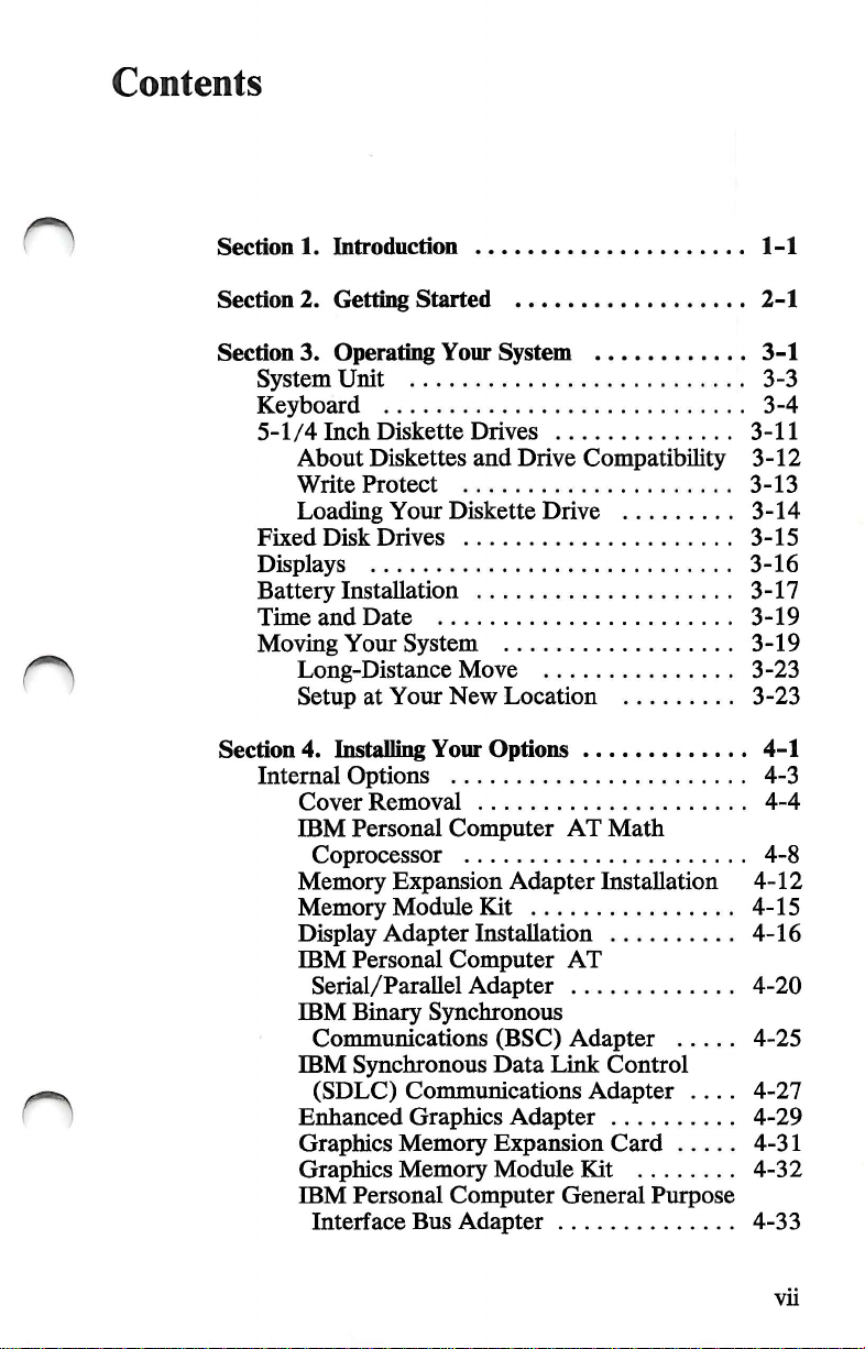
Contents
n
Section
Section
Section
1.
2.
3.
System
Keyboard
5-1/4
About
Write
Loading
Fixed
Displays
Battery
Time
Moving
Long-Distance
Setup
Section
4.
Internal
Cover
IBM
Memory
Memory
Display
IBM
IBM
IBM
Enhanced
Graphics
Graphics
IBM
Introduction
Getting
Operating
Started
Your
System
Unit
Inch
Diskette
Diskettes
Protect
Your
Disk
Drives
Drives
and
Diskette
Installation
and
Date
Your
System
Move
at
Your
New
Location
Installing
Your
Options
Options
Removal
Personal
Computer
Coprocessor
Expansion
Module
Adapter
Personal
Serial/Parallel
Binary
Communications
Synchronous
(SDLC)
Communications
Kit
Installation
Computer
Adapter
Synchronous
(BSC)
Data
Graphics
Memory
Memory
Personal
Interface
Bus
Expansion
Module
Computer
Adapter
Drive
Compatibility
Drive
AT
Adapter
Installation
AT
Adapter
Link
Adapter .... 4-27
Adapter
Kit
General
Math
Control
Card
Purpose
1-1
2-1
3-1
3-3
3-4
3-11
3-12
3-13
3-14
3-15
3-16
3-17
3-19
3-19
3-23
3-23
4-1
4-3
4-4
4-8
4-12
4-15
4-16
4-20
4-25
4-29
4-31
4-32
4-33
vu
Page 10

IBM
Personal
and
Control
IBM
PC
Adapter
Cover
External
Options
IBM
Monochrome
IBM
Color
IBM
Enhanced
IBM
Personal
IBM
Communications
IBM
Personal
Adapter
IBM
3.5
Computer
Adapter-.
Network
Adapter
Installation
Installation
Display
Display
Color
Computer
Computer
Cable
Inch
External
Data
Acquisition
Display
Display
Cable
AT
Serial
Diskette
4-35
4-37
4-39
4-42
4-44
4-46
4-48
4-50
Stand . 4-52
4-56
4-58
Drive
..
4-60
Sections.
Appendix
Introduction
French ...
German ...
Italian
Spanish ...
U.K.
U.S.
TESTING
A.
Keyboard
EngUsh
English
YOUR
.
.
.
SYSTEM
Templates
5-1
A-1
A-3
A-5
A-1
A-9
A-11
A-13
A-15
Glossary Glossary
Index
Index
n
1
1
o
vm
Page 11

n
Section
The
unit
supports a variety
used
cable.
To
choose
functions
is
the
Color
your
additional
system.
1.
Introduction
IBM
Personal
is
the
central
Computer
part
of
to
send
data
to
tailor a system
internal
you
to
and
need.
Color/Graphics
Display,
system.
an
external
You
can
memory,
XT
of
your
IBM
options.
your
your
external
An
The
system,
particular
options
example
Monitor
option,
Model
keyboard,
is
of
Adapter
to
286
computer
attached
needs,
that
perform
an
internal
that
be
attached
add a display, a printer,
or
other
options
to
expand
system
and
which
is
by a coiled
you
can
the
option
allows
a
to
your
n
Hardware
system.
have a functioning
Model
• Hardware
• Software
• You.
alone
Three
286;
does
elements
IBM
not
form a completely
must
be
present
Personal
Computer
functioning
in
order
to
XT
Introduction
1-1
Page 12

Hardware
Minimum
• System
• Keyboard
• Display.
hardware
unit
requirements
with
one
diskette
are:
drive
n
n
1-2
n
Introduction
Page 13

Software
Software
• Disk
• Game
• Financial
• Programming
• Other
can
be
any
operating
program
program
language
programs
of
the
system
of
your
following:
such
as
BASIC
choice.
o
Introduction
1-3
Page 14

You
You
are
the
most
working
of
to
hardware.
IBM
hardware
and
Operations,
important
computer
software
will
help
you
system.
element
together.
become
of a properly
You
bring
This
familiar
the
elements
manual,
with
the
Guide
n
1-4
The
Guide
manual.
information
By
answering
"Getting
Continue
Introduction
to
Operations
You
will
probably
it
contains
the
questions
Started,"
with
the
you
next
can
be
use
each
time
in
will
be
section.
used
as a reference
only a portion
you
open
the
the
next
section,
led
through
the
of
the
book.
book.
O
Page 15
Section
2.
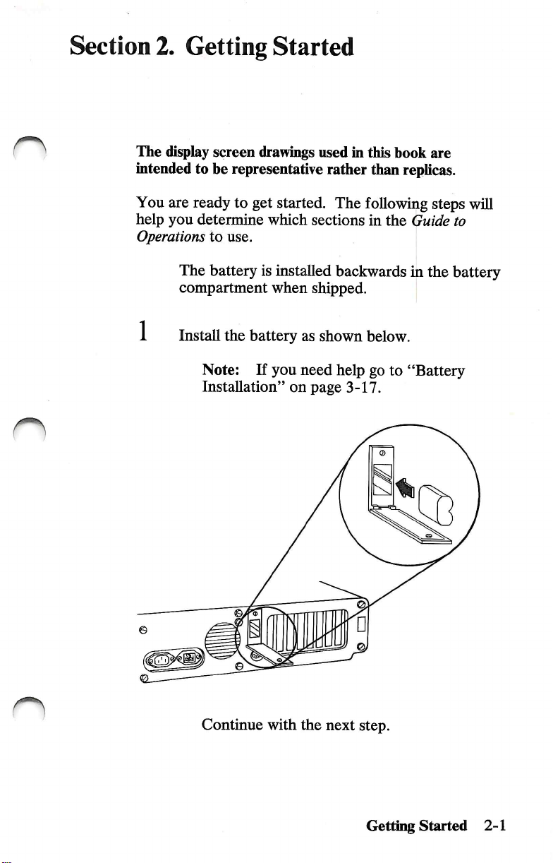
The
display
intended
You
are
help
you
Operations
The
compartment
Getting
screen
to
he
ready
determine
to
use.
battery
Started
drawings
representative
to
get
started.
which
is
installed
when
used
in
this
rather
sections
than
The
following
in
backwards
shipped.
hook
are
replicas.
steps
the
Guide
in
the
will
to
battery
Install
the
battery
Note:
Installation"
Continue
If
with
you
on
as
shown
need
page
the
next
below.
help
go
3-17.
step.
to
"Battery
Getting
Started
2-1
Page 16
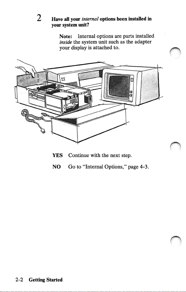
Have
your
system
all
your
internal
unit?
options
been
installed
in
Note:
inside
your
YES
NO
Internal
the
system
display
Continue
Go
is
with
to
"Internal
options
unit
attached
are
such
to.
the
next
Options,"
parts
as
the
step.
page
installed
adapter
n
4-3.
2-2
Gettii^
Started
n
Page 17
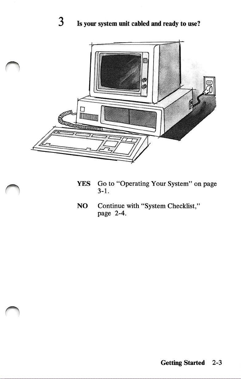
3
Is
your
system
unit
cabled
and
ready
to
use?
n
YES
NO
Go
to
"Operating
3-1.
Continue
page
2-4.
with
"System
Your
System"
Checklist,"
Getting
on
page
Started
2-3
Page 18

System
Checklist
IMPORTANT:
your
system
□
unit
The
system
mounting
Cover
Before
be
unit
screws
Mounting
you
sure:
cover
are
Screws
connect
is
installed.
on
the
and
power
the
cover
cord
to
n
2-4
Getting
n
Started
Page 19

n
n
□
The
below.
Equipment
"Setup
manual.
location
serial
Information"
of
the
system
numbers
foldout
Setup
Foldout
unit
serial
are
recorded
found
Information
number
in
VUV
tllAlU*/*"
wVAu* a «4«4«
atlC-a-MMKMir
-----
/U
g*
on
this
CAA
NMCIf
is
the
shown
n
System
Serial
Getting
Unit
Number
Started
2-5
Page 20
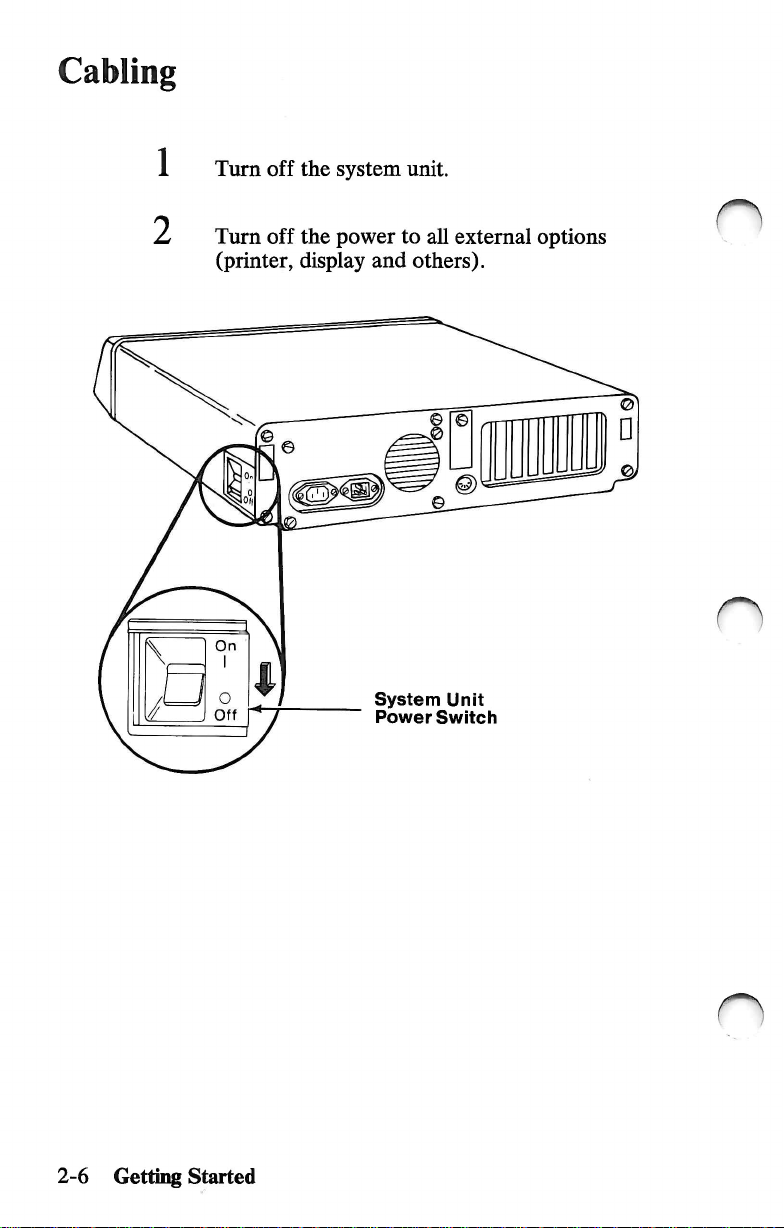
Cabling
1 Turn
2
off
Turn
off
(printer,
a
the
system
the
power
display
and
System
Power
unit.
to
all
external
others).
Unit
Switch
options
2-6
Getting
Started
n
Page 21
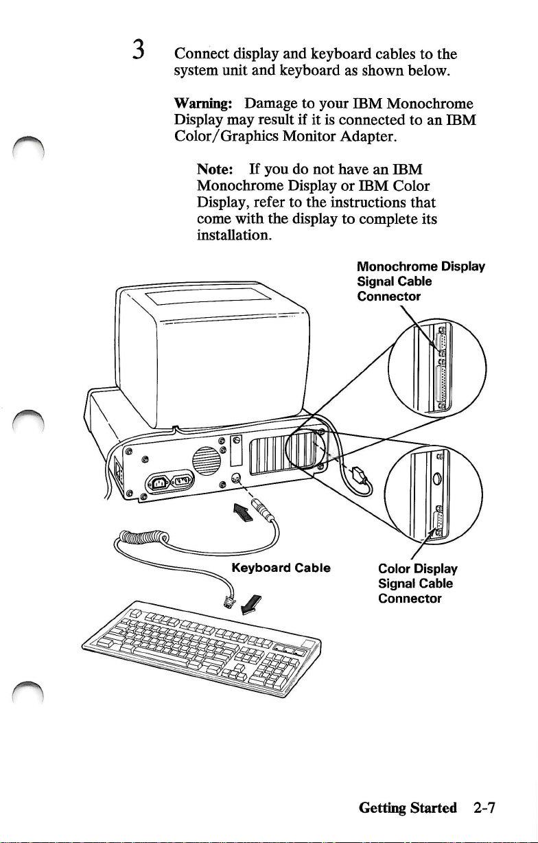
Connect
system
display
unit
and
and
keyboard
keyboard
as
shown
cables
to
the
below.
n
Warning:
Display
Color/Graphics
Note:
Monochrome
Display,
come
installation.
Damage
may
If
refer
with
result
Monitor
you
do
Display
to
the
display
to
your
IBM
if
it
is
connected
Adapter.
not
have
or
IBM
the
instructions
to
complete
Monochrome
Signal
Connector
Monochrome
to
an
an
IBM
Color
that
its
Cable
IBM
Display
Keyboard
Cable
Color
Signal
Connector
Getting
Started
Display
Cable
2-7
Page 22

Are
YES
NO
you
installing a printer
Continue
Go
with
to
Step 9 on
the
page
at
this
next
step.
2-10.
time?
IBM
Monochrome
and
Printer
Connect
adapter
Note:
Monochrome
Adapter,
connect
adapter.
Display
Adapter
the
on
your
Connect
if
your
printer
cable
system
your
Display
you
have
printer
or
Screws
to
the
appropriate
unit.
printer
and
Printer
one.
Otherwise,
to
any
parallel
Serial/Parallel
Adapter
to
the
IBM
n
2-8
6
Getting
Started
Tighten
the
screws.
n
Page 23

If
your
printer
instructions
installation.
is
that
come
not
already
with
set
up,
it
to
complete
refer
to
its
the
8
CAUTION:
Connect
grounded
Connect
then
the
plug
it
into
to a properly
outlet.
printer
power
the
electrical
cord
to
the
outlet.
printer,
Getting
Started
2-9
Page 24

CAUTION
This
product
designed
a
properly
electrical
for
grounded
shock.
is
equipped
the
user's
receptacle
with a line
safety.
It
to
cord
is
to
he
avoid
and
pli^
used
with
possible
Connect
end
first.
this
Connect
plug
it
into
the
power
the
electrical
cord
to
the
system
outlet.
unit,
then
n
n
2-10
Getting
Started
Power
Cord
n
Page 25

10
Connect
options
the
power
as
shown.
cords
for
other
external
Monochrome
Power
Cord
Note:
detachable
external
the
If
your
power
option
electrical
Display
external
cord,
first
and
outlet.
option
connect
then
has
it
plug
a
to
it
into
the
n
Color
Power
Display
Cord
CAUTION:
Connect
properly
outlet.
to
a
grounded
Getting
Started
2-11
Page 26

1 1 Did
IBM
your
internal
or
an
authorized
options?
IBM
dealer
install
all
of
Internal
system
attached
YES
NO
options
unit
such
to.
Go
to
3-1.
Continue
this
section.
are
parts
installed
as
the
adapter
"Operating
with
Your
"Setup
inside
your
display
System"on
Program"
next
the
is
page
in
2-12
Getting
Started
n
Page 27
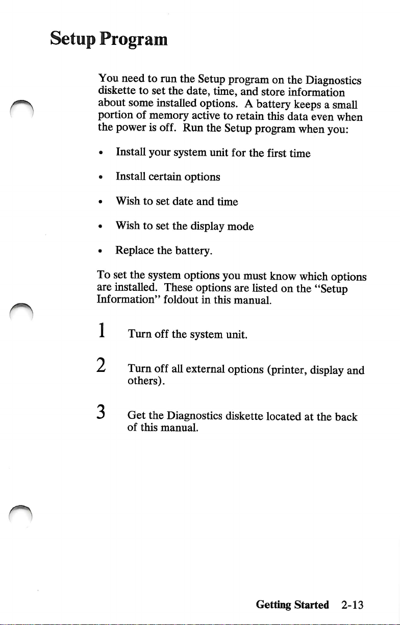
Setup
*1^
'
Program
You
need
to
run
diskette
about
portion
the
to
set
some
of
memory
power
is
installed
off.
the
the
Run
date,
Setup
program
time,
and
on
the
store
information
options. A battery
active
to
the
Setup
retain
this
program
data
Diagnostics
keeps a small
even
when
when
you:
O
• Install
• Install
•
Wish
•
Wish
• Replace
To
set
are
installed.
Information"
1 Turn
2
your
certain
to
set
to
set
the
the
system
These
foldout
off
Turn
off
others).
Get
the
Diagnostics
of
this
manual.
system
date
the
battery.
the
all
unit
for
the
options
and
time
display
options
options
system
external
mode
you
must
are
in
this
manual.
unit.
options
diskette
first
time
know
which
listed
on
the
(printer,
located
options
"Setup
display
at
the
back
and
Getting
Started
2-13
Page 28

4
Insert
the
Diagnostics
diskette
into
drive
A.
5
6
Diskette
Turn
your
Turn
on
others).
Drive
Handie
display
all
external
controls
options
in-use
Light
clockwise.
(printer,
display
and
2-14
Getting
Started
Page 29

7
Turn
on
the
system
unit.
O
8
9
Adjust
coinfort.
Did
a
screen
following?
XXX
KB
OK
16X — System
(RESUIftE="F1"KEYl
the
controls
appear
Options
on
your
with
Not
Set
display
a
message
(Run
for
similar
Setup)
eye
to
the
(X
can
be
YES
Press
your
Information"
Setup
This
the
installed.
on
the
back
NO
Continue
any
number.)
F1
and
screen.
program
program
date,
time,
Your
"Setup
of
your
with
follow
Refer
foldout
allows
manual.
the
instructions
to
the
"Setup
as
you
questions.
you
to
and
which
installed
Information"
the
next
options
options
step.
Getting
answer
teU
your
you
are
foldout
Started
in
on
the
system
have
hsted
the
2-15
Page 30

10
Did
the
The
IBM
DIAGNOSTICS
Version
(C)Copyright
X.XX
foUowing
Personal
IBM
screen
Computer
Corp.
XXXX,
appear?
n
XXXX
SELECT
0 - SYSTEM
1 - FORMAT
2 - COPY
3 - PREPARE
4-SETUP
9 - END
SELECT
7
YES
NO
1 1
Do
run
YES
AN
OPTION
CHECKOUT
OISKEHE
OISKEHE
SYSTEM
DIAGNOSTICS
THE
ACTION
Continue
Remove
Your
you
want
the
Setup
Press 4 then
instructions
"Setup
the
Setup
DESIRED
with
the
System,"
to
set
program?
Information"
program
FOR
MOVING
the
next
diskette
the
Enter
on
and
Section
time,
date,
your
screen.
foldout
questions.
step.
go
to
"Testing
5.
display
'),
and
follow
Refer
as
you
mode,
or
the
to
the
answer
n
2-16
NO
Getting
Started
Remove
Your
System"
the
diskette
on
and
page
go
3-1.
to
"Operating
n
Page 31

Section
3.
Operating
Your
System
o
System
Keyboard
5-1/4
Fixed
Displays
Battery
Time
Moving
Unit
Inch
Diskette
About
Write
Loading
Long-Distance
Setup
Diskettes
Protect
Disk
Drives
Installation
and
Date
Your
at
Your
Diskette
System
Your
New
Drives
and
Move
Location
Drive
Compatibility
Drive
3-3
3-4
3-11
3-12
3-13
3-14
3-15
3-16
3-17
3-19
3-19
3-23
3-23
Operating
Your
System
3-1
Page 32

Notes:
3-2
Operatii^
Your
r)
System
Page 33

n
System
Unit
The
It
processes
system
software.
comes
BASIC. A wide
yom
main
part
of
data
through a set
The
IBM
with
an
installed
dealer.
your
IBM
and
controls
of
instructions
Personal
program
variety
of
computer
the
Computer
programs
is
operations
called a program
language
is
the
system
of
your
XT
Model
called
available
286
IBM
from
unit.
or
Operating
Your
System
3-3
Page 34
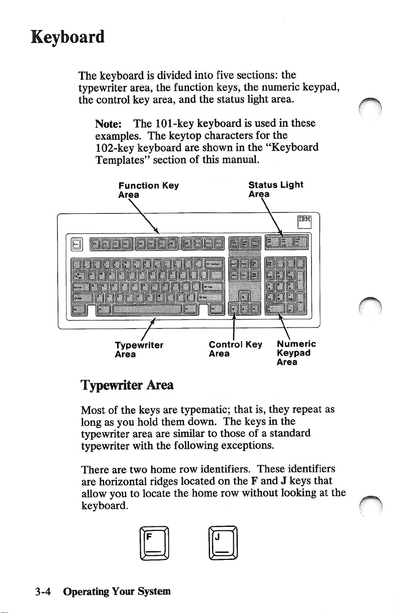
Keyboard
The
keyboard
typewriter
the
control
is
divided
area,
the
key
area,
into
five
function
and
keys,
the
status
sections:
the
light
the
numeric
area.
keypad,
Note:
The
examples.
102-key
keyboard
Templates"
Function
Area
H
7=
Typewriter
Area
Typewriter
Most
of
the
long
as
you
hold
typewriter
typewriter
area
with
101-key
The
keytop
section
Key
y
Area
keys
are
them
are
the
keyboard
characters
are
shown
of
this
manual.
JpL
Control
Area
typematic;
down.
similar
following
The
to
those
exceptions.
is
used
in
for
the
in
the
"Keyboard
Status
Area
Light
i
lllpj
Key
that
keys
Numeric
Keypad
Area
is,
they
in
the
of a standard
these
IBM
repeat
as
n
3-4
There
are
allow
keyboard.
Operating
are
horizontal
you
Your
two
home
ridges
to
locate
System
row
identifiers.
located
the
home
These
on
the F and J keys
row
without
looking
identifiers
that
at
the
Page 35
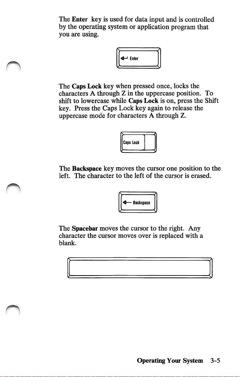
The
by
the
you
The
Enter
are
Caps
key
is
used
operating
system
using.
Lock
key
for
or
Enter
when
characters A through Z in
shift
to
lowercase
key.
Press
the
uppercase
The
left.
mode
Backspace
The
character
while
Caps
Caps
Lock
for
characters A through
Caps
Lack
key
moves
to
the
data
input
and
apphcation
pressed
the
key
the
left
once,
uppercase
Lock
is
on,
again
to
cursor
of
the
one
cursor
is
controlled
program
locks
that
the
position.
press
the
release
the
Z.
position
is
erased.
To
Shift
to
the
The
Spacebar
character
blank.
the
moves
cursor
the
moves
'
Backspace
cursor
to
over
is
Operating
the
right.
replaced
Your
with
System
Any
a
3-5
Page 36

The
Tab
key
moves
stops
are
defined
application
program
the
in
your
manual.
cursor
to
the
operating
Tab
next
tab
system
or
stop.
Tab
Pressing
t5rpewriter
alphabetic
capital
characters
appear.
The
described
application
entered
entering
The
described
application
either
area
keys
letters.
shown
Alt
key
performs a variety
in
your
program
by
holding
the
3-digit
Ctrl
key
in
your
program
performs a variety
Shift
key
to
the
are
pressed,
When
on
the
■O
operating
manual.
down
ASCII
operating
manual.
changes
uppercase
the
characters
other
keys
upper
Shift
Alt
system
ASCII
either
code
system
portion
of
Alt
on
of
the
keys
mode.
are
pressed,
of
functions.
manual
codes
key
and
the
numeric
functions.
manual
in
the
When
appear
the
the
These
or
can
then
or
keys
be
keypad.
These
as
are
n
are
3-6
Operating
Your
Ctrl
n
System
Page 37

The
Esc
system
or
key
functions
application
are
described
program
manual.
Esc
in
your
operating
When
screen
The
operating
manual.
The
any
the
Print
presentation
purpose
system
Pause
other
key
key
Screen
of
the
key
is
printed.
Scroll
manual
or
temporarily
to
continue.
is
pressed, a copy
Print
Screen
Sys
Rq
Lock
key
is
defined
application
Scroll
Lock
stops
your
Pause
Break
of
the
in
your
program
program.
Press
Operating
Your
System
3-7
Page 38

Function
Key
Area
Twelve
under
your
Numeric
Pressing
switches
in
down
The
when
changes
function
program
control.
operating-system
Keypad
the
Numeric
the
number
the
Num
Lock
to
use
the
keypad
is
typing
many
cursor
arranged
control
keys,
above
Their
or
Area
Lock
keys
mode,
numeric
Num
Lock
7
Home
the
keypad
like a calculator
numbers.
keys
the
typewriter
operation
application-program
(Num
to
Lock)
cursor
shift
key
as
control
cursor
Pressing
back
to
number
9
PgUp
6
is
defined
key
must
control
to
Num
area,
manual.
one
keys.
be
held
save
time
Lock
keys.
are
in
time
While
keys.
again
n
3-8
The
numeric
This
identifier
that
allows
keypad
Operating
Your
ke5fpad
is a horizontal
you
to
without
looking
System
has
an
locate
the
at
3
PgDn
Enter
Del
identifier
ridge
center
the
keyboard.
on
located
of
the 5 key.
on
the
numeric
the
key
Page 39
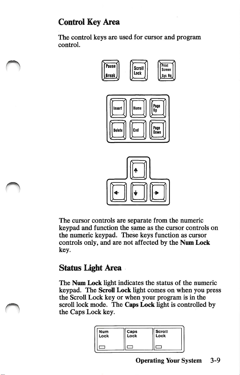
Control
The
control.
Key
control
Area
keys
are
used
for
cursor
and
program
The
cursor
kejrpad
the
controls
and
numeric
only,
key.
—
Pause
BreaJ^
Insert
Delete
controls
function
kej^ad.
and
are
the
These
are
Scroll
Lock
Home
End
separate
same
as
keys
not
affected
s ^
Print
Screen
Sys
R(|
Paee
Up
Page
Down
from
the
numeric
the
cursor
function
by
the
as
Num
controls
on
cursor
Lock
Status
The
kejrpad.
the
scroll
the
Light
Num
Lock
The
Scroll
Lock
lock
Caps
Lock
Area
light
ScroU
key
mode.
key.
Num
Lock
!=□
indicates
Lock
light
or
when
The
Caps
Caps
Lock
CZl
Operating
the
comes
your
Lock
status
of
on
when
program
light
is
controlled
Scroll
Lock
!=□
Your
the
muneric
you
is
in
the
System
press
by
3-9
Page 40

Keyboard
You
can
positions
To
adjust,
keyboard
Height
adjust
for
typing
turn
legs
your
yom
into
the
Adjustment
keyboard
coiMort.
keyboard
desired
to
two
over
position.
different
and
set
both
o
3-10
Operating
Your
(O
System
Page 41
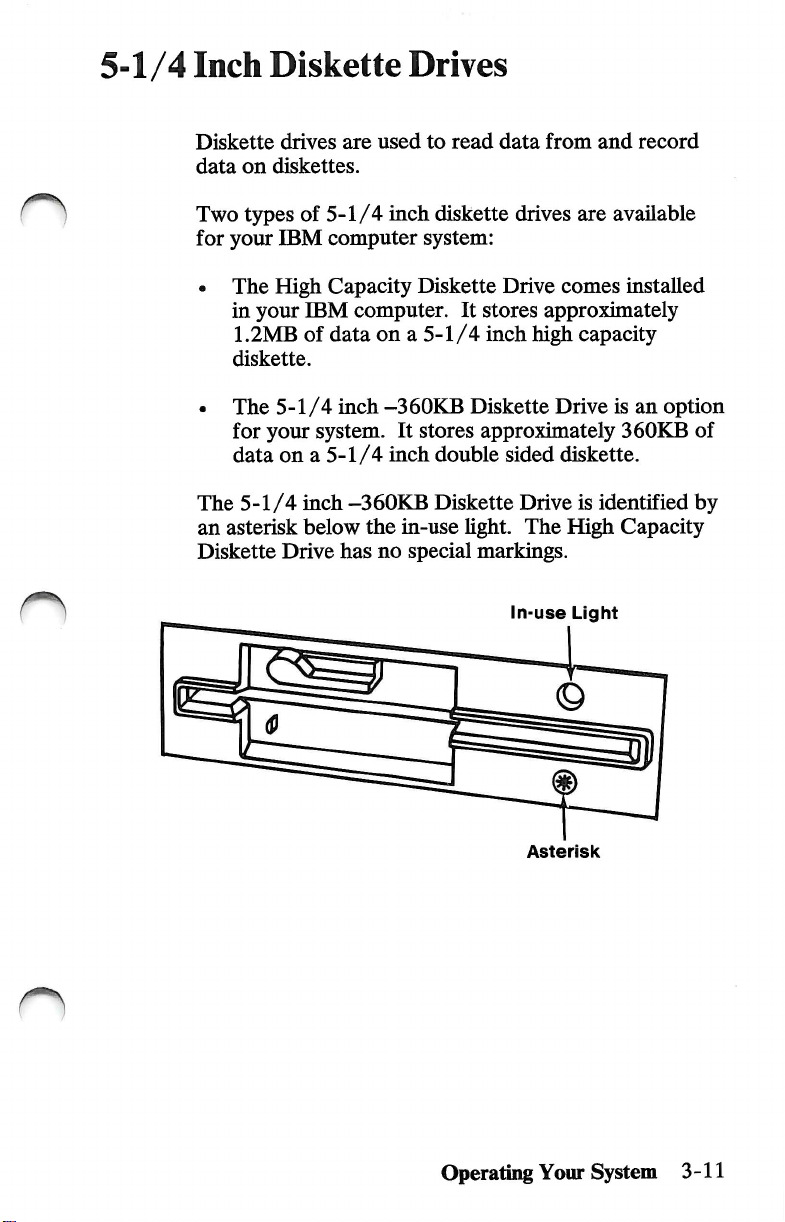
5-1/4
Inch
Diskette
Drives
Diskette
data
Two
for
• The
drives
on
diskettes.
tjT)es
your
IBM
High
in
your
1.2MB
diskette.
• The
The
an
Diskette
5-1/4
for
your
data
on a 5-1/4
5-1/4
asterisk
Drive
are
of
5-1/4
computer
Capacity
IBM
computer.
of
data
inch
system.
inch
-360KB
below
the
has
used
to
read
inch
diskette
system:
Diskette
It
stores
on a 5-1/4
-360KB
It
stores
inch
inch
Diskette
approximately
double
Diskette
in-use
no
light.
special
markings.
data
from
and
drives
Drive
are
comes
approximately
high
capacity
Drive
sided
diskette.
Drive
is
identified
The
High
In-use
Light
record
available
installed
is
an
option
360KB
of
by
Capacity
n
Asterisk
Operating
Your
System
3-11
Page 42

About
Diskettes
A
diskette
protective
data.
Your
successful
with
is a 5-1/4
plastic
selection
operation
You
can
with
a
Doubie
Drive
High
Drive
Sided
a
Capacity
You
can
and
jacket.
of
the
READ
WRITE
Drive
inch
Compatibility
magnetic
Diskettes
correct
of
your
IBM
the
following
1
s,
1
0
1
Single
Sided
|
a
0
on
the
disk
are
used
diskette
is
computer.
diskettes:
f
DoubleVided
©>
c
}
Double
Sided
|
0
following
diskettes:
inside
a
to
store
important
to
the
n
3-12
with
Doubie
Drive
with
High
Drive
Operating
Your
a
Sided
a
Capacity
System
I
Single
Sid>a
|
0
Once
you
diskettes,
them
only
Capacity
write
you
In a High
drive.
on
can
a
0
o>
0
these
use
a
0
n
Page 43

Write
Protect
n
When a diskette
be
written
a
diskette,
with a write-protect
information
is
write
protected,
(recorded)
cover
the
on
notch
tab.
on a diskette,
the
diskette.
on
the
side
If
you
want
remove
the
no
information
To
write
protect
of
the
diskette
to
write
(record)
write-protect
Write
Protect
Tab
can
tab.
Operating
Your
System
3-13
Page 44

Loading
Your
1
Diskette
When
clicks
indicates
drive.
you
have
into
place.
the
Drive
fully
When
system
unit
inserted
the
in-use
is
using
Drive
the
diskette,
hght
the
diskette
A
is
on,
it
it
n
3-14
Diskette
To
rotate
and
diskette
Operating
Your
Drive
Handle
remove a diskette
the
diskette
pull
your
diskette
when
the
System
from
drive
out.
in-use
in-use
the
diskette
lever
counterclockwise
Do
not
remove
hght
is
on.
Light
drive,
n
n
your
Page 45

Fixed
Disk
You
Operating
your
Drive
can
use
System
fixed
disk.
an
operating
(DOS)
system
to
store
such
as
and
retrieve
the
IBM
data
Disk
from
When
in-use
the
hght
system
is
on.
In-use
unit
Light
is
using
""■""niiiimiiiiiii
the
fixed
disk
drive,
its
Operating
Your
System
3-15
Page 46

Displays
All
IBM
Power
Power-on
on.
color
displays
control
turns
indicator
have a Power
your
display
lights
when
control.
on
and
your
display
off.
The
is
The
turned
Color
displays
have
• 40-column
the
screen.
• 80-column
across
You
on
your
refer
The
system
is
turned
Note:
Display,
the
the
screen.
can
change
Diagnostics
to
"Setup
IBM
Monochrome
unit.
It
on
or
If
you
refer
display
for
two
modes
mode
allows
mode
allows
the
mode
diskette.
Program"
display
is
turned
off.
do
to
on
not
the
instructions
control
of
operation.
40
large
80
smaller
by
using
the
For
more
in
Section
plugs
or
off
when
have
an
IBM
locations.
characters
characters
Setup
across
program
information
2.
into
the
rear
the
system
Color
that
come
with
of
unit
the
3-16
Power-on
Control Control Control
Operating
Your
Contrast
System
Power-on
Indicator
n
Brightness
Page 47

Battery
Installation
1
CAUTION
The
lithium
Number
result
Replacement
IBM
CAUTION
The
lithium
severe
polarized
100°C
water.
Turn
hattery
62X0339.
in
ignition
batteries
authorized
battery
hum
risk.
connector,
(212°F),
off
the
system
must
he
replaced
Use
of
another
or
explosion
can
dealer.
presents a fire,
Do
not
disassemble,
incinerate,
unit
of
the
be
ordered
recharge,
or
expose
and
all
with
Part
battery
hattery.
explosion,
remove
heat
could
from
the
above
an
contents
external
options.
or
to
2
Remove
compartment
the
screw
door.
and
open
the
battery
Operating
Your
System
3-17
Page 48
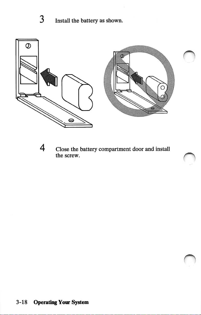
3
Install
the
battery
as
shown.
n
4
Close
the
battery
the
screw.
compartment
door
and
install
n
3-18
Operatmg
Your
System
Page 49

n
Time
and
Date
The
time
using
For
more
page
2-13.
and
date
for
your
IBM
the
Setup
program
information
on
your
refer
to
computer
Diagnostics
"Setup
can
Program"
be
set
diskette.
on
^
Moving
Your
To
back
your
instructions.)
When
continue
1
System
prevent a loss
up
aU
disk
operating
you
have
with
Load
of
this
Turn
of
the
files
completed
Step
the
Diagnostics
manual)
on
the
data
stored
before
system
1.
into
system
unit.
on a fixed
moving
manual
backing
diskette
drive
your
for
up
A.
disk
system.
backup
your
files,
(found
at
the
drive,
(See
back
n
Operatii^
Your
System
3-19
Page 50
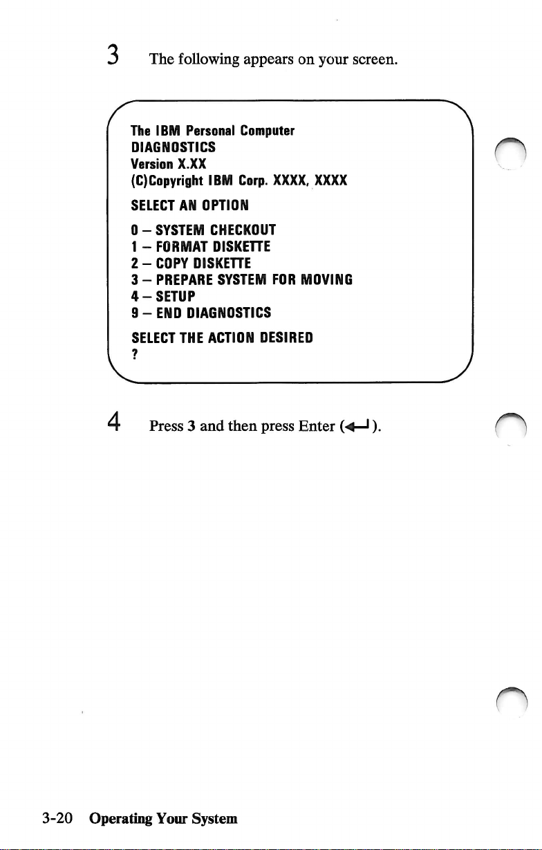
The
following
The
IBM
Personal
DIAGNOSTICS
Version
(C)Copyright
X.XX
IBM
appears
Computer
Corp.
XXXX,
on
your
XXXX
screen.
O
SELECT
0 - SYSTEM
1 - FORMAT
2 - COPY
3 - PREPARE
4 - SETUP
9 - END
SELECT
AN
OISKEHE
DIAGNOSTICS
THE
Press 3 and
OPTION
CHECKOUT
OISKEHE
SYSTEM
ACTION
then
FOR
DESIRED
press
Enter
MOVING
(-4—').
3-20
Operating
Your
System
Page 51

When
the
screen,
moved.
The
IBM
DIAGNOSTICS
Version
(C)Copyright
SELECT
your
Personal
X.XX
IBM
AN
OPTION
following
fixed
Computer
Corp.
XXXX,
message
disk
XXXX
appears
drive
is
ready
to
on
be
your
6
1
8
0 - SYSTEM
1 - FORMAT
2 - COPY
3 - PREPARE
4 - SETUP
9-ENO
SELECT
?
3
ORIVE
IS
PREPAREO
TURN
7
CHECKOUT
OISKEHE
DIAGNOSTICS
THE
ACTION
C
SYSTEM
Remove
Turn
off
Turn
off
DISKETTE
SYSTEM
FOR
MOVING
OESIREO
FOR
MOVING
OFF
the
Diagnostics
the
system
all
external
unit.
options.
diskette.
Operating
Your
System
3-21
Page 52

9
Put a shipping
Rotate
the
insert
diskette
into
drive
each
lever
diskette
clockwise.
drive.
Shipping
10
Note:
insert,
Unplug
electrical
options.
If
use a blank
insert
your
system
outlet.
you
Also,
do
not
have a shipping
diskette.
unit
power
unplug
cord
from
any
external
n
the
3-22
11
Disconnect
Operating
Your
and
System
secure
all
cables
and
cords.
n
Page 53

Long-Distance
If
you
materials
them
If
you
well
to
Move
saved
that
to
pack
are
using
avoid
the
your
your
any
original
different
damage.
shipping
IBM
computer
units.
cartons,
cartons
system
cushion
and
came
your
packing
in,
use
units
Setup
at
Your
When
it
To
page
your
carefully.
set
up
2-6.
New
system
and
cable
Location
arrives
your
system,
at
the
new
location,
refer
to
"Cabling,"
unpack
Operating
Your
System
3-23
Page 54

Notes:
o
n
3-24
Operating
Your
n
System
Page 55
Section
4.
Installing
Your
Options
n
n
Internal
Options
Cover
IBM
Memory
Memory
Display
IBM
Removal
Personal
Coprocessor
Expansion
Module
Adapter
Personal
Serial/Parallel
IBM
Binary
Synchronous
Communications
IBM
Synchronous
(SDLC)
Enhanced
Graphics
Graphics
IBM
Interface
IBM
and
IBM
Adapter
Cover
External
IBM
IBM
IBM
IBM
IBM
IBM
Adapter
IBM
Communications
Graphics
Memory
Memory
Personal
Bus
Personal
Control
PC
Network
Installation
Installation
Options
Monochrome
Color
Display
Enhanced
Personal
Communications
Personal
Cable
3.5
Inch
Computer
Adapter
Kit
Installation
Computer
AT
Adapter
(BSC)
Data
Link
Adapter
Expansion
Module
Computer
Adapter
Computer
Adapter
Adapter
Color
Computer
Computer
External
General
Data
Display
Display
Display
Cable
AT
Diskette
AT
Math
Installation
Adapter
Control
Adapter ....
Card
Bat
Purpose
Acquisition
Stand . 4-52
Serial
Drive
. .
4-3
4-4
4-8
4-12
4-15
4-16
4-20
4-25
4-27
4-29
4-31
4-32
4-33
4-35
4-37
4-39
4-42
4-44
4-46
4-48
4-50
4-56
4-58
4-60
n
Installing
Your
Options
4-1
Page 56

Notes:
C)
4-2
Installing
Your
o
Options
Page 57

Internal
Options
Internal
unit.
system
•
• Display
• Diskette
• Printer
Some
your
will
this
use
are
instructions
option's
system.
Before
the
options
Some
of
the
are
listed
Memory
options
IBM
find
section.
the
installing
expansion
adapters
drives
or
communication
do
Personal
these
options
If
you
instructions
is
not
enclosed
illustrations
you
begin
cover
using
the
are
parts
installed
internal
below.
not
Computer
are
in
listed
installing
procedure
options
options
include
Hsted
installation
on
installing
this
section.
on
the
with
that
may
differ
any
internal
in
inside
available
adapters.
instructions
XT
Model
the
Contents
one
of
these
If
the
Contents
option.
sUghtly
this
Some
from
options,
section.
the
system
for
your
286.
You
page
options,
option
page,
use
of
you
the
your
remove
for
of
the
O
Required
•
• SmaU-size,
Tools
Medium-size,
flat-blade
flat-blade
screwdriver
screwdriver.
Internal
Options
4-3
Page 58
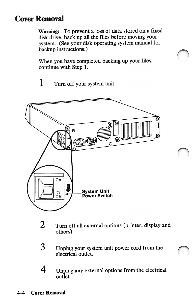
Cover
Removal
Warning!
disk
system.
backup
When
continue
1
To
drive,
back
(See
instructions.)
you
have
with
Turn
off
prevent a loss
up
all
your
disk
completed
Step
1.
your
system
of
the
files
operating
backing
unit.
data
stored
before
moving
system
up
your
on a fixed
your
manual
for
fUes,
O
4-4
2
3
Cover
Turn
others).
Unplug
electrical
Unplug
outlet.
Removal
System
"
Power
off
all
your
outlet.
any
Unit
Switch
external
system
external
options
unit
power
options
(printer,
from
display
cord
from
the
electrical
and
the
Page 59

Note
the
locations
disconnect
unit.
them
of
all
from
the
cables
or
back
of
cords,
your
and
system
Monochrome
Display
Cord
Power
System
Power
Cord
Keyboard
Cable
Other
Cables
Cover
Removal
4-5
Page 60

6
Remove
Cover
To
a.
b.
the
Mounting
remove
SUde
Tilt
the
cover
the
the
cover
mounting
Screws
cover:
cover
to
the
up
to
remove
screws.
front
until
it
from
it
stops.
the
base.
o
n
4-6
Cover
n
Removal
Page 61

n
8 If
you
record
foldout
Type
Label
have
not
recorded
the
drive
type
in
this
manual.
on
the
fixed
the
"Setup
Type
disk
drive
Information"
IMumber
type,
Continue
are
Notes:
a.
b.
with
installing.
This
section's
numbers
If
your
the
instaUation
packaged
differ
sUghtly
the
instructions
table
for
options
option
is
with
from
Setup
Information
Foldout
for
of
contents
hsted
in
not
hsted
in
instructions
it.
Some
of
the
your
system.
Cover
the
option
gives
page
this
manual.
this
manual,
that
came
ihustrations
Removal
you
use
4-7
Page 62
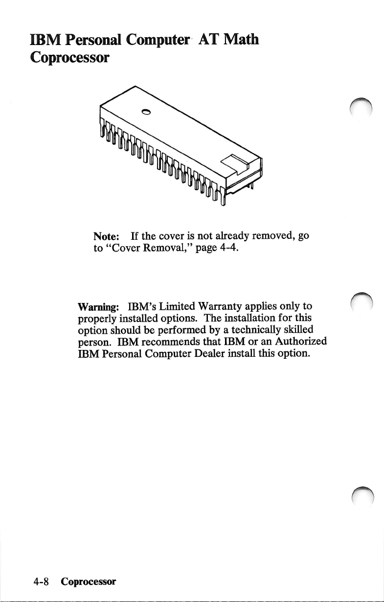
IBM
Personal
Coprocessor
Computer
AT
Math
Note:
to
Warning:
properly
option
person.
IBM
If
"Cover
IBM's
installed
should
IBM
Personal
the
cover
is
not
Removal,"
Limited
options.
be
performed
recommends
Computer
page
Warranty
The
that
Dealer
already
4-4.
by a technically
removed,
applies
installation
IBM
or
an
install
this
go
only
to
for
this
skilled
Authorized
option.
n
4-8
Coprocessor
Page 63

1
Remove
slots.
all
adapters
installed
in
the
expansion
O
2
Note:
Carefully
locations.
Assemble
• Insert
• Insert
Some
adapters
disconnect
the
safety
slot Q into
slot Q into
have
cables
the
cables
protector
attached.
noting
as
connector
shown
slot
slot
Q.
below.
Coprocessor
4-9
Page 64
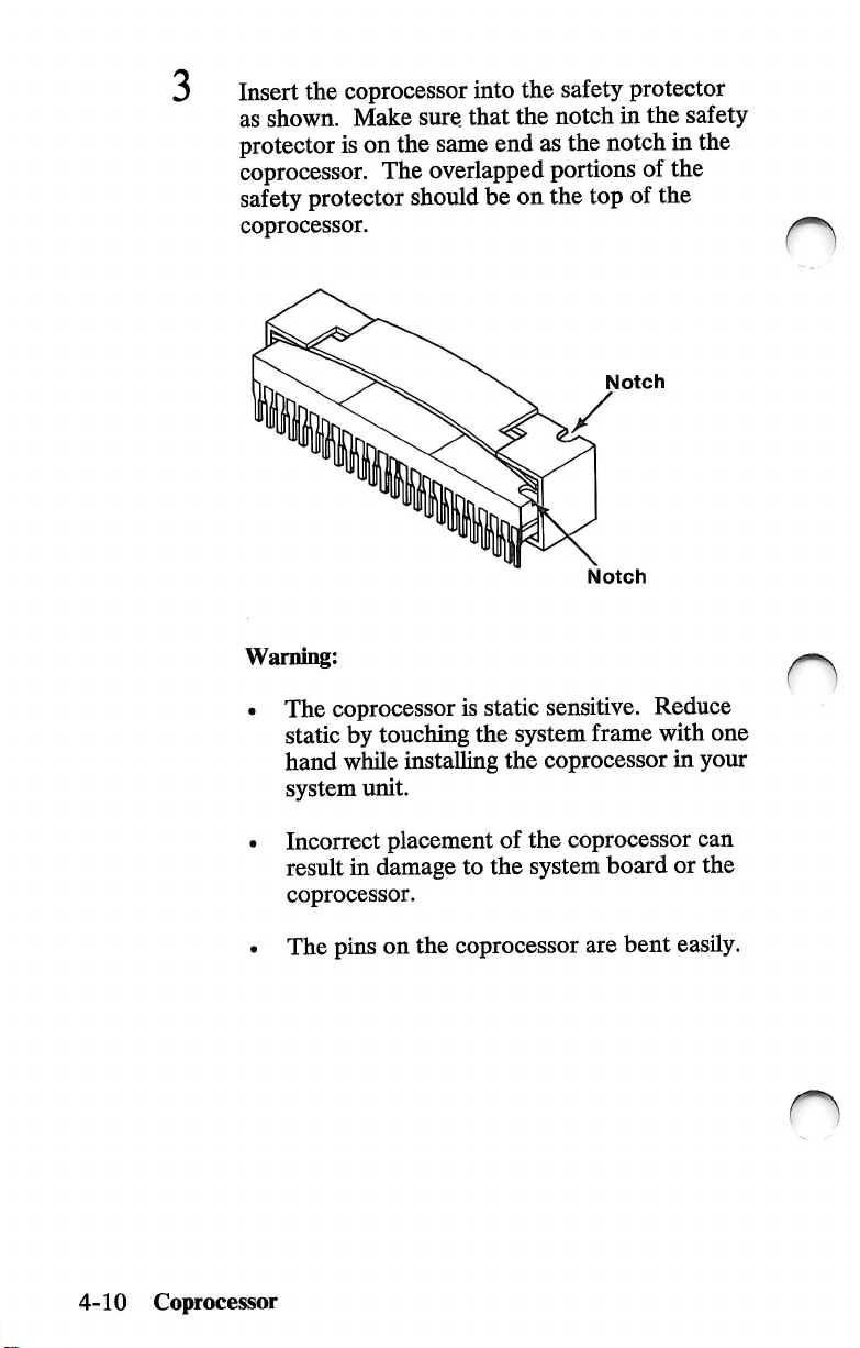
Insert
as
the
coprocessor
shown.
protector
coprocessor.
safety
coprocessor.
Warning:
The
static
hand
system
Make
sure
is
on
the
The
protector
should
coprocessor
by
touching
while
installing
unit.
into
the
safety
that
the
notch
same
end
as
the
overlapped
is
the
portions
be
on
the
static
sensitive.
system
the
coprocessor
protector
in
the
notch
of
top
of
the
Notch
Notch
Reduce
frame
with
safety
in
the
the
one
in
your
n
4-10
Coprocessor
Incorrect
result
coprocessor.
The
placement
in
damage
pins
on
of
the
to
the
system
the
coprocessor
coprocessor
board
are
bent
can
or
the
easily.
Page 65

Make
sure
the
with
the
notch
of
the
coprocessor
the
coprocessor
notch
on
on
its
connector.
with
the
firmly
into
the
coprocessor
Mgn
connector
place.
lines
the
pins
and
press
up
i
UJ
Notch
□□□
I
Notch
O
IMPORTANT;
Diagnostics
installed
is
correct.
If
you
installed,
procedures
"Cover
diskette
and
verify
have
other
continue
for
Installation,"
Run
that
internal
with
those
the
Setup
after
all
the
options
the
installation
options.
page
4-42.
program
your
options
installed
that
If
not,
Coprocessor
on
are
devices
need
go
to
your
list
to
be
4-11
Page 66
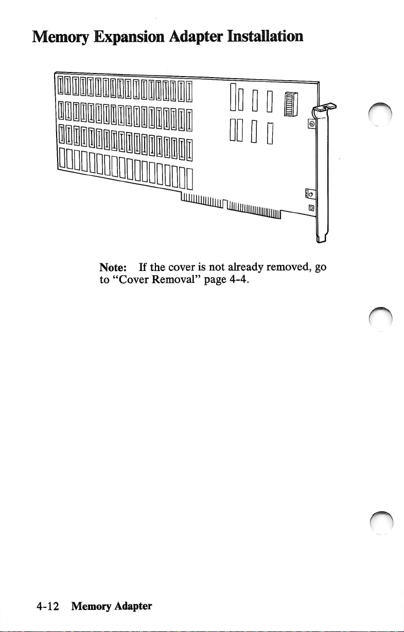
Memory
Expansion
Adapter
Installation
Note:
to
"Cover
If
the
cover
Removal"
is
not
page
already
4-4.
removed,
go
n
o
4-12
Memory
Adapter
Page 67
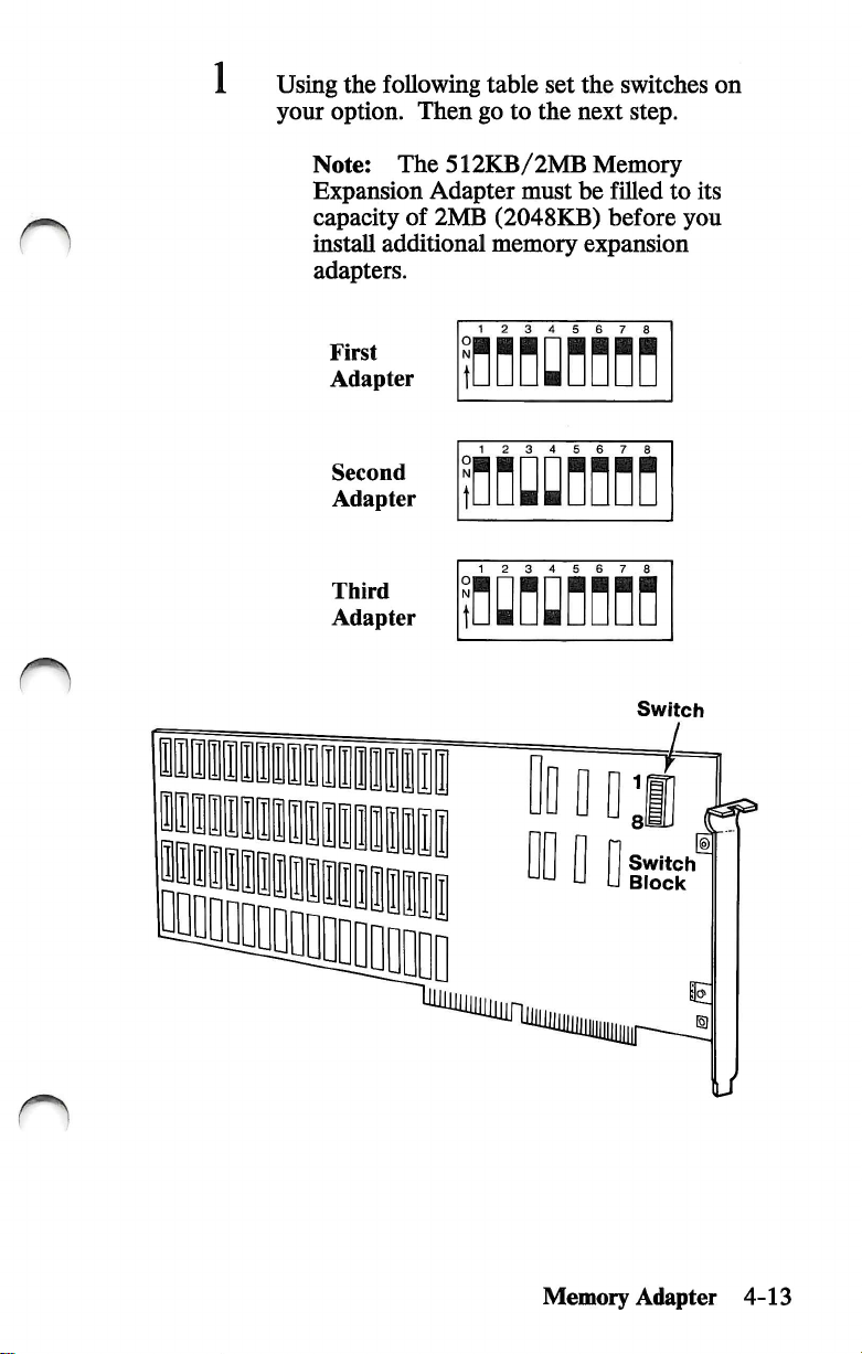
Using
the
your
option.
following
Then
table
go
to
set
the
the
switches
next
step.
on
n
Note;
Expansion
capacity
install
adapters.
First
Adapter
The
of
additional
Second
Adapter
Third
Adapter
Adapter
2MB
512KB/2MB
must
(2048KB)
memory
1 2 3 4
1 2 3 4 5 6
Memory
be
filled
to
before
expansion
5
n
7
n
Switch
its
you
n
Memory
Switch
Block
Adapter
4-13
Page 68
2
You
in
any
can
install
available
the
Memory
dual-connector
Expansion
expansion
Adapter
slot.
3
Go
to
"Adapter
Installation,"
page
4-39.
n
4-14
Memory
o
Adapter
Page 69
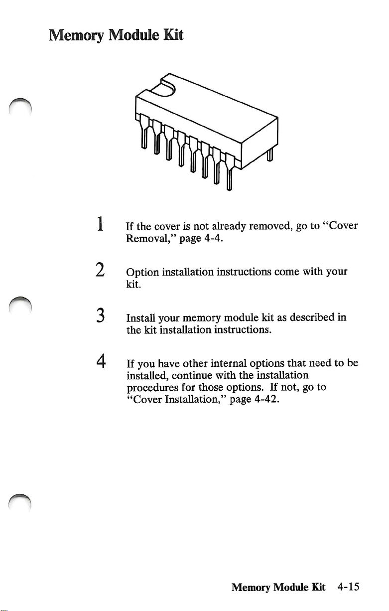
n
Memory
Module
If
Removal,"
the
Kit
cover
is
not
page
already
4-4.
removed,
go
to
"Cover
O
L
3
4
Option
kit.
Install
the
If
installed,
procedures
"Cover
installation
your
memory
kit
installation
you
have
other
continue
for
Installation,"
instructions
module
instructions.
internal
with
the
those
options.
page
come
kit
options
installation
If
4-42.
with
your
as
described
that
not,
go
in
need
to
be
to
Memory
Module
Kit
4-15
Page 70
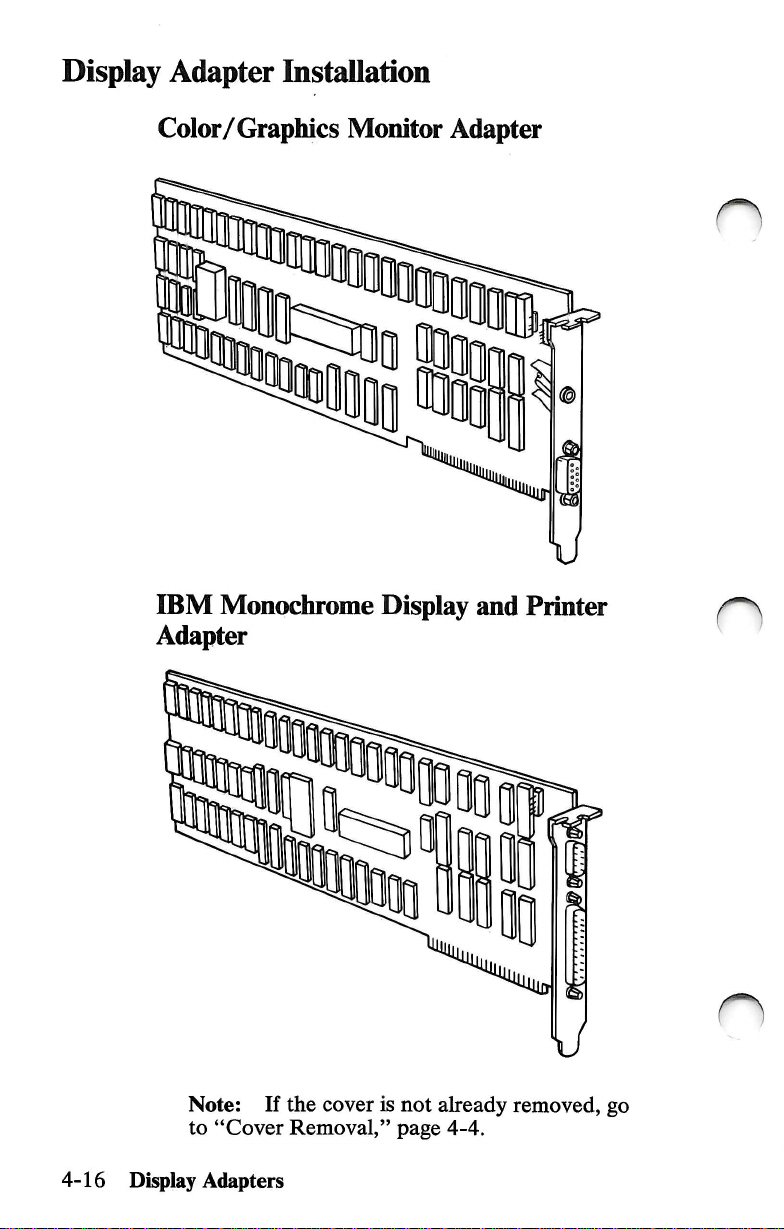
Display
Adapter
InstaUation
Color/Graphics
IBM
Monochrome
Monitor
Adapter
Adapter
m
Display
and
Printer
4-16
Note:
to
"Cover
Display
Adapters
^0
If
the
cover
Removal,"
is
not
page
already
4-4.
removed,
O
go
Page 71

n
Installation
If
you
install
Adapter,
port.
The
IBM
installed
Rear
Panel
Requirements
an
IBM
its
printer
Color/Graphics
in
expansion
Monochrome
port
becomes
Monitor
slot
1.
1 2
3
4
5
Display
the
primary
Adapter
6 7 8
and
printer
must
Printer
be
Display
Adapters
4-17
Page 72
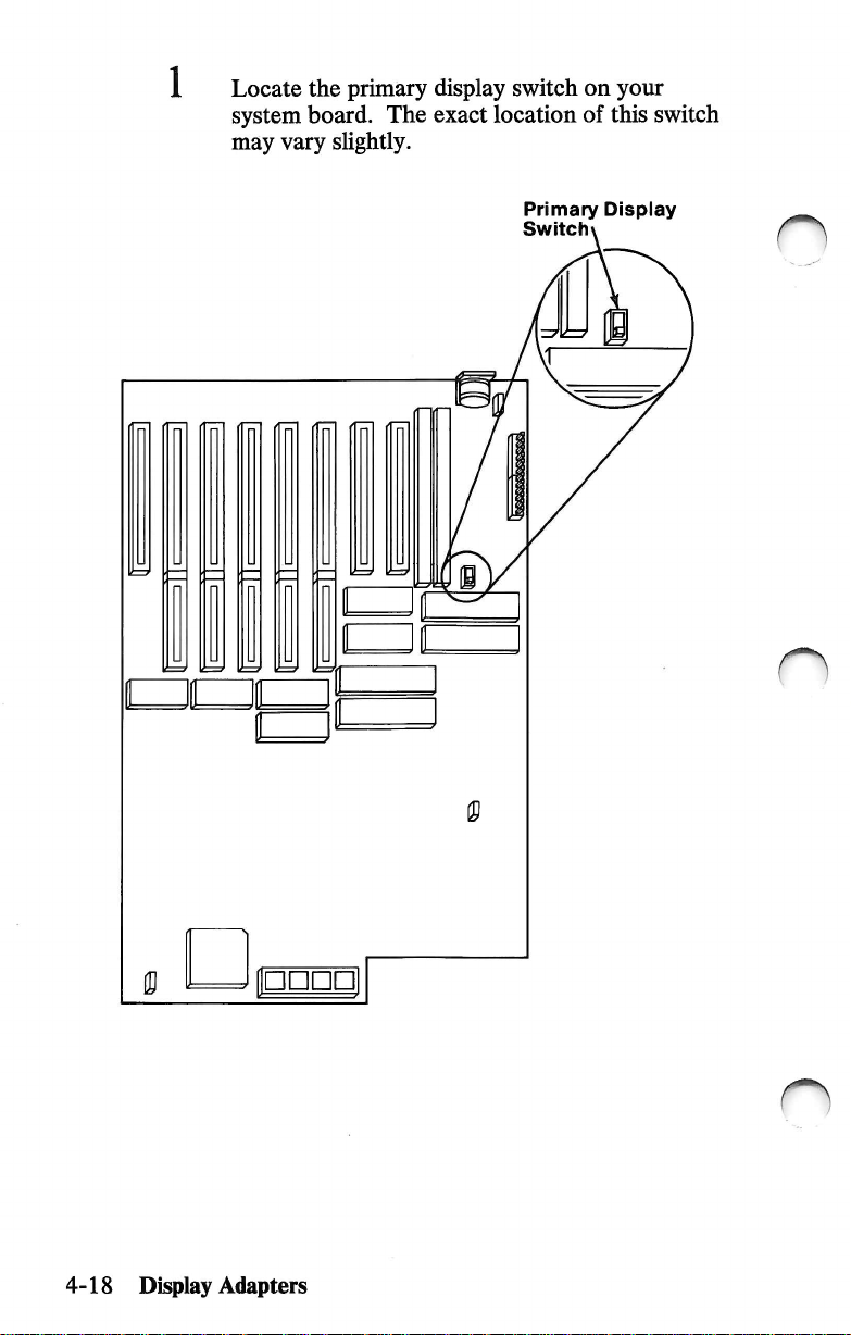
Locate
system
may
the
board.
vary
primary
The
sUghtly.
display
exact
switch
location
on
of
your
this
switch
Primary
Switchx
Display
n
4-18
Display
Adapters
Page 73

Is
there
your
YES
NO
system?
more
than
Set
the
switch
display
turn
Set
installed
that
your
the
switch
system
in
one
for
you
want
for
your
display
system
the
primary
to
unit
on).
the
display
adapter
come
unit.
installed
display
on
adapter
(the
when
in
you
Monochrome
t
3
4
Locate
manual.
IMPORTANT:
Diagnostics
installed.
Note:
primary
Use a ballpoint
display
Display
Front
the
"Setup
Indicate
diskette
switch
Primary
Display
Switch
of
System
Information"
the
Run
if
Color
Unit
primary
the
Setup
after
all
pen
to
set
the
necessary.
Display
I
foldout
display
program
your
type.
options
in
on
this
your
are
5
Go
to
"Adapter
Installation,"
page
Display
Adapters
4-39.
4-19
Page 74

IBM
Personal
Adapter
Computer
AT
Serial/Parallel
n
4-20
Note:
to
Serial/ParaUel
If
"Cover
Adapter
the
Removal,"
cover
is
not
already
page
4-4.
removed,
go
Page 75
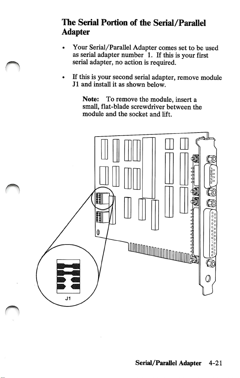
The
Serial
Adapter
Portion
of
the
Serial/Parallel
• Your
as
serial
serial
• If
this
J1
and
Note:
small,
module
Serial/Parallel
adapter
adapter,
is
your
second
install
it
To
flat-blade
and
Adapter
number
no
action
serial
as
shown
remove
screwdriver
the
socket
1.
is
required.
below.
the
module,
and
comes
If
adapter,
set
this
is
your
remove
insert
between
lift.
to
be
first
a
the
used
module
n
Serial/Parallel
Adapter
U
4-21
Page 76

The
Parallel
Adapter
Portion
of
the
Serial/Parallel
• Your
Serial/Parallel
as
parallel
adapter
Serial/Parallel
• If
this
is
your
remove
module
Note;
small,
flat-blade
module
To
and
Adapter
number
Adapter,
second
remove
Serial/Parallel
J2
and
screwdriver
the
socket
comes
1.
no
action
install
the
it
module,
and
set
If
this
is
is
required.
Adapter,
as
shown
insert
between
lift.
to
be
your
first
below.
a
the
used
n
n
4-22
Serial/Parallel
Adapter
u
Page 77

How
your
system
The
parallel
can
be
used
number
(printer
1),
number
assigns
portion
as
LPT2
of
the
parallel
adapter
(printer
3).
paraUel
printer
Serial/Parallel
LPTl
number
ports:
Adapter
(printer
2),
or
LPT3
Note:
and
Printer
Adapter
IBM
Monochrome
Adapter
as
LPTl
The
following
adapter
One
ADAPTERS
One
Serial/Parallel
Two
ADAPTERS
1st
Serial/Parallel
2nd
Serial/Parallel
is
Serial/Parallel
INSTALLED
Serial/Parallel
INSTALLED
When
an
IBM
Adapter
are
used
in
your
Display
is
always
(printer
used
number
combinations
identified
Adapter
Adapter
Adapter
by
your
Adapter
Adapters
Monochrome
Display
and a Serial/Parallel
system
by
and
Printer
your
system
unit,
the
unit
1).
show
how
each
parallel
system
LPTl
LPTl
X
X
unit.
LPT2
LPT2
X
LPT3
LPT3
Serial/Parallel
Adapter
4-23
Page 78

Monochrome
Serial/Parallel
Display
Adapter
and
Printer
Adapter
with
one
ADAPTERS
IBM
Printer
Serial/Parallel
INSTALLED
Monochrome
Adapter
Adapter
Display
Monochrome
Serial/Parallel
ADAPTERS
IBM
Printer
1st
Serial/Parallel
2nd
Serial/Parallel
1 You
INSTALLED
Monochrome
Adapter
available
Display
Adapter
Adapter
can
install
expansion
and
Display
and
Adapters
and
the
Serial/Parallel
slot.
1 2
3 4 5
LPT1
X
Printer
Adapter
LPT1
X
6 7 8
LPT2
LPT2
Adapter
X
X
LPT3
with
two
LPT3
X
in
any
n
(
—^
)
4-24
Rear
Panel
2
Serial/ParaUel
Go
to
"Adapter
Adapter
Installation,"
page
4-39.
o
Page 79

IBM
Binary
Synchronous
Communications
n
(BSC)
Adapter
□
Q
0
0
Binary
Note:
to
Synchronous
If
"Cover
the
Removal,"
cover
is
not
already
page
4-4.
Conununications
removed,
(BSC)
Adapter
go
4-25
Page 80

The
Binary
Adapter
alternate
of
the
jumper
is
shown
modes
Synchronous
below.
are
on
connector
Communications
The
determined
primary
by
the
P3.
(BSC)
and
position
Jumper
for
Primary
• Installing
the
• Installing
the
Install
Position
Mode
the
Jumper
for
I
P3
the
primary
mode.
the
alternate
jumper
Position
Alternate
I
P3
jumper
jumper
mode.
on
pins 2 and 4 selects
on
pins 1 and 3 selects
according
Connectors
and
have
shown
operation
Mode
the
I
P1
to
your
P2
must
jumpers
for
adapter
P2
needs.
P1
as
correct
of
4-26
L
3
Binary
Synchronous
You
can
install
Communications
expansion
Go
to
"Adapter
the
Adapter
slot.
Installation,"
Communications
Binary
Synchronous
in
(BSC)
any
available
page
4-39.
Adapter
25-Pin
Connector
n
Page 81
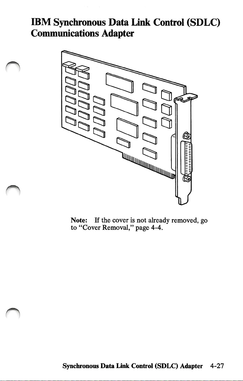
IBM
Synchronous
Data
Link
Control
(SDLC)
n
Conununications
Adapter
□
n
Note;
to
Synchronoiis
If
"Cover
the
cover
Removal,"
Data
Link
is
not
page
Control
already
4-4.
(SDLC)
removed,
Adapter
go
4-27
Page 82

Rear
You
can
Control
any
available
Panel
install
(SDLC)
the
expansion
1 2
Synchronous
Conununications
slot.
3 4 5
Data
Adapter
6 7 8
Link
in
C)
4-28
2
Synchronous
Go
to
"Adapter
Data
Link
Control
Installation,"
(SDLC)
page
4-39.
Adapter
Page 83

n
Enhanced
Graphics
Adapter
O
1 If
2
3
4
the
Removal,"
Option
adapter.
IBM
option.
Discard
Compare
diskette
Diagnostics
diskette
Discard
cover
is
not
already
page
4-4.
installation
Use
Personal
Package
the
with
diskette
with
the
first
instructions
the
instruction
Computer
1.
version
the
version
the
higher
page
removed,
AT
number
number
in
this
version
of
Package
go
come
package
to
install
of
the
Diagnostics
of
the
manual.
Keep
number.
2.
to
"Cover
with
your
for
the
your
the
Enhanced
Graphics
Adapter
4-29
Page 84

0
Insert
the
"IBM
Graphics
this
Adapter
page.
Personal
Installation
Computer
Instructions"
Enhanced
after
7
8
Install
Personal
Installation
If
installed,
procedures
"Cover
your
adapter
Computer
Instructions."
you
have
other
continue
for
Installation,"
as
described
Enhanced
internal
with
those
options
the
installation
options.
page
4-42.
in
the
"IBM
Graphics
that
need
If
not,
go
Adapter
to
be
to
4-30
Enhanced
Graphics
Adapter
Page 85

O
n
Graphics
Graphics
Memory
Expansion
Card
4-31
4
"Cover
If
installed,
procedures
3
Install
installation
you
Installation,"
page
4-42.
have
continue
for
other
those
internal
with
options.
the
options
installation
If
not,
that
go
need
to
to
your
instructions.
expansion
card
as
described
in
the
be
2
Personal
card.
Option
1
If
Removal,"
the
Use
installation
Computer
the
instruction
instructions
AT
to
package
install
cover
page
is
not
4-4.
already
removed,
come
your
for
with
the
option.
IBM
your
go
to
"Cover
EgB
O
Memory
CD
O
:
d
CD
O
E
CD
do
:
CD
O
CD
CD
CD
CD
CD
CD
CD
en
CD
CD
CD
Expansion
Card
Page 86

Graphics
Memory
Module
Kit
D
1 If
2
3
4
the
Removal,"
Option
kit.
Personal
Install
the
If
you
installed,
procedures
"Cover
cover
is
not
already
page
4-4.
installation
Use
the
instruction
Computer
your
memory
kit
installation
have
other
continue
for
Installation,"
instructions
package
AT
to
module
instructions.
internal
with
the
those
options.
page
removed,
install
kit
options
installation
4-42.
go
to
"Cover
come
with
your
for
the
IBM
your
option.
as
described
that
need
If
not,
go
to
in
to
be
4-32
Graphics
Memory
Module
Kit
Page 87

IBM
Personal
Computer
General
Purpose
n
Interface
Bus
1 If
Removal,"
2
Option
adapter.
IBM
option.
Adapter
the
cover
is
riot
already
page
4-4.
installation
Use
Personal
instructions
the
instruction
Computer
removed,
package
AT
to
go
to
come
with
for
install
your
"Cover
your
the
O
3
4
Discard
Compare
diskette
Diagnostics
diskette
General
Package
the
with
the
diskette
with
the
Purpose
Interface
1.
version
number
version
higher
number
in
your
version
Bus
(GFEB)
manual.
of
the
of
number.
Adapter
Diagnostics
the
Keep
the
4-33
Page 88

J
Discard
the
first
page
of
Package
2.
6
7
8
Insert
Purpose
Instructions"
Install
Personal
"Cover
the
"IBM
Interface
Bus
If
installed,
procedures
your
adapter
Computer
(GPIB)
you
Adapter
have
other
continue
for
Installation,"
Personal
after
those
Computer
Bus
Adapter
this
page.
as
described
General
Installation
internal
with
the
options.
page
Installation
in
Purpose
Instructions."
options
installation
4-42.
that
If
not,
General
the
"IBM
Interface
need
to
go
to
O
be
4-34
General
Purpose
Interface
Bus
(GPIB)
Adapter
Page 89
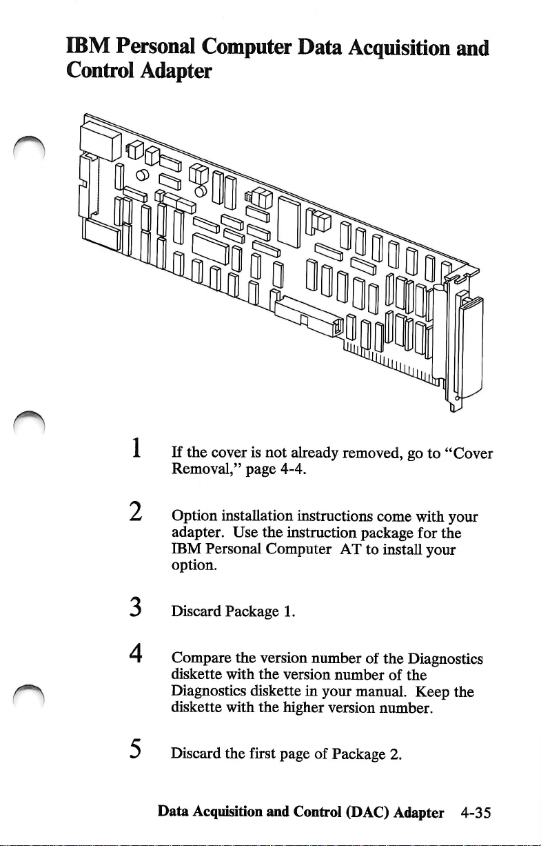
IBM
Personal
Computer
Data
Acquisition
and
Control
Adapter
1 If
the
cover
Removal,"
0
a
is
not
page
already
4-4.
removed,
go
to
"Cover
^
3
4
Option
adapter.
IBM
option.
Discard
Compare
diskette
Diagnostics
diskette
Discard
Data
installation
Use
Personal
Package
the
with
with
the
Acquisition
instructions
the
instruction
Computer
1.
version
the
version
diskette
the
higher
first
page
and
Control
AT
number
number
in
your
version
of
Package
come
package
to
install
of
the
of
manual.
number.
(DAC)
with
your
for
the
your
Diagnostics
the
Keep
the
2.
Adapter
4-35
Page 90

Insert
Acquisition
Instructions"
/
Install
Personal
Control
the
"IBM
and
after
your
adapter
Computer
Adapter
Personal
Control
this
Installation
Computer
Adapter
page.
as
described
Data
Acquisition
Instructions."
Data
Installation
in
the
"IBM
and
8
If
you
have
other
installed,
procedures
"Cover
continue
for
Installation,"
internal
with
those
options
the
installation
options.
page
4-42.
that
If
not,
need
to
go
to
be
1^
4-36
Data
Acquisition
and
Control
(DAC)
n
Adapter
Page 91
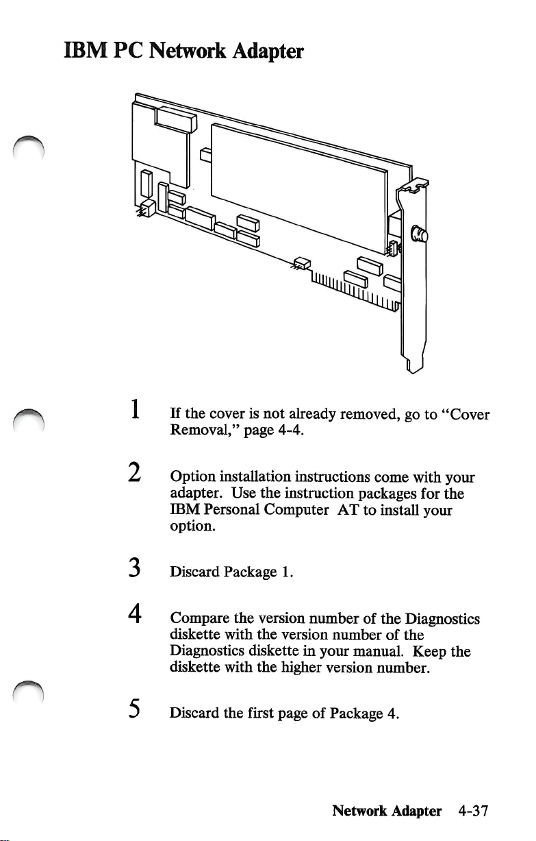
IBM
PC
Network
1
Adapter
If
the
cover
Removal,"
page
is
not
already
4-4.
removed,
go
to
"Cover
2
3
4
Option
adapter.
IBM
option.
Discard
Compare
diskette
Diagnostics
diskette
Discard
installation
Use
the
Personal
Computer
Package
the
version
with
the
diskette
with
the
the
first
instructions
instruction
packages
AT
to
1.
number
version
in
your
higher
page
of
of
number
manual.
version
Package
Network
come
with
your
for
the
install
the
number.
your
Diagnostics
of
the
Keep
the
4.
Adapter
4-37
Page 92

0
Insert
the
"IBM
Installation
Instructions"
PC
Network
Adapter
after
this
page.
1
8
Install
Network
If
installed,
procedures
"Cover
your
adapter
Adapter
you
have
other
continue
for
Installation,"
as
described
Installation
internal
with
the
those
options.
page
Instructions."
options
installation
4-42.
in
that
If
not,
the
"IBM
need
go
to
PC
to
be
_ -
4-38
Network
Adapter
Page 93

n
Adapter
Installation
r^
Notes:
1.
Do
not
install
installation
2.
The
table
options
3.
If
installation
Some
system.
your
of
listed
option
the
option
procedures
of
contents
in
is
instructions
the
illustrations
this
manual.
not
listed
gives
\l
before
in
this
page
in
this
that
came
differ
Adapter
you
read
manual.
numbers
manual,
packaged
slightly
from
Installation
the
for
read
with
your
the
it.
4-39
Page 94

Remove
slot
expansion
Rear
Panel
the
cover
screw Q and
Save
the
slot
cover.
expansion
screw
and
discard
the
o
4-40
Adapter
InstaOation
Page 95

Hold
the
it
into
the
ggggggogggl
>
adapter Q by
expansion
the
slot.
top
and
Top
firmly
View
press
3
4
Note:
support
expansion
came
Install
If
you
installed,
procedures
"Cover
Your
brackets
slots.
with
your
the
screw
have
other
continue
for
those
Installation,"
IBM
computer
installed
If a support
option,
Q
you
removed
internal
with
options
the
options.
page
Adapter
comes
for
bracket
it
is
not
installation
If
not,
4-42.
Installation
with
aU
needed.
in
Step
that
need
go
to
1.
to
be
4-41
Page 96

Cover
Installation
IMPORTANT:
make
sure
you
• Recorded
Information"
Set
Adapter
the
the
primary
Installation"
Before
have:
Setup
foldout.)
display
you
install
information.
switch.
in
the
'^
Setup
Information
Foldout
(See
this
section.)
system
(See
M.VIU
iA(fc%
M.
"
•lU
IUUKMA.lMjJi.IA
Primary
Switch
unit
the
"Setup
f*'
lint rtlit
*
«„H
./t
luM
"Display
Display
cover
n
4-42
Cover
Installation
Page 97

Install
the
system
unit
cover.
Install
the
Cover
cover
Mounting
n
If
you
have
options
outside
"External
"CabUng,"
of
your
Options,"
page
mounting
Screws
to
install
system
unit,
page
2-6.
screws.
that
attach
continue
4-44.
If
to
with
not,
go
the
to
Cover
Installation
4-43
Page 98

External
Options
External
unit.
system
• Displays
• Printer
• Cables.
Use
installation
Refer
page
is
convenient
Required
•
•
options
Some
of
the
are
Usted
or
communication
the
procedures
instructions
to
this
section's
numbers.
for
Note:
come
this
Medium-size,
When
with
manual.
Tools
your
Medium-size,
attach
to
external
below:
in
this
that
table
Install
external
you.
separate
options,
flat-blade
Philhps
the
outside
options
devices
section
come
of
contents
options
operating
you
screwdriver
screwdriver
of
your
available
along
with
with
your
for
in
instructions
may
file
(printers
system
for
the
option.
specific
any
order
them
in
only).
your
that
O
4-44
External
Options
Page 99

1 Turn
off
your
system
unit.
n
2
3
Turn
off
all
external
others).
Unplug
others)
Continue
you
power
from
with
are
installing.
options
cords
(system,
electrical
the
outlets.
Power
Cord
instructions
(printer,
printer,
for
display
display
the
option
and
and
that
Notes;
a.
This
numbers
b.
If
your
the
packaged
may
section's
option
instaUation
differ
table
for
options
is
with
it.
sHghtly
of
contents
hsted
in
not
hsted
in
instructions
Some
from
that
of
the
your
External
lists
page
this
manual.
this
manual,
came
iUustrations
system.
Options
use
4-45
Page 100
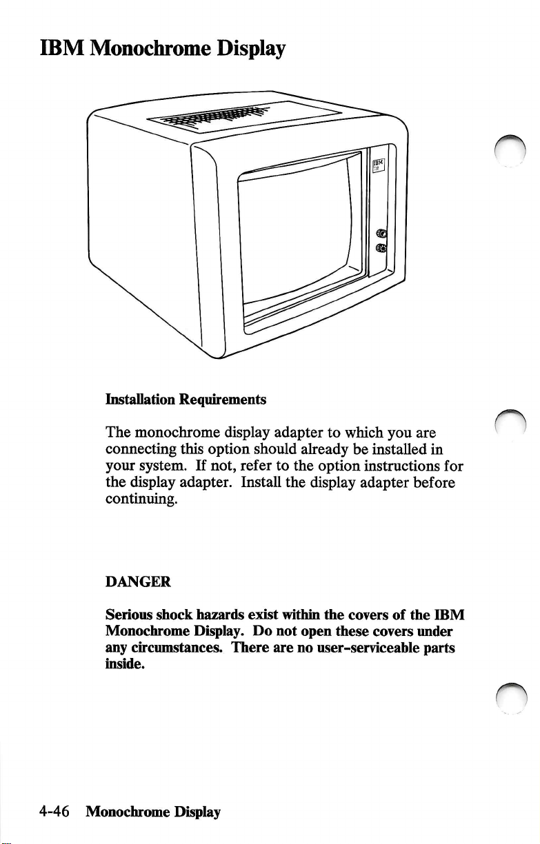
IBM
Monochrome
Display
Installation
The
monochrome
connecting
your
the
display
Requirements
this
system.
If
adapter.
continuing.
DANGER
Serious
Monochrome
any
inside.
shock
hazards
Display.
circumstances.
display
option
not,
should
refer
Install
exist
Do
There
adapter
to
already
to
the
option
the
display
within
the
not
open
are
no
user-serviceahle
which
you
be
installed
instructions
adapter
covers
these
of
covers
are
in
for
before
the
IBM
under
parts
4-46
Monochrome
Display
 Loading...